Predictive Analytical and Thermal Modeling of Orthogonal Cutting ...
Predictive Analytical and Thermal Modeling of Orthogonal Cutting ...
Predictive Analytical and Thermal Modeling of Orthogonal Cutting ...

You also want an ePaper? Increase the reach of your titles
YUMPU automatically turns print PDFs into web optimized ePapers that Google loves.
Yig˘it Karpat<br />
Tug˘rul Özel 1<br />
e-mail: ozel@rci.rutgers.edu<br />
Department <strong>of</strong> Industrial <strong>and</strong> Systems<br />
Engineering,<br />
Rutgers University,<br />
Piscataway, NJ 08854<br />
1 Introduction<br />
<strong>Modeling</strong> metal cutting processes with the aid <strong>of</strong> plasticity<br />
theory has been <strong>of</strong> great interest to researchers. Mainly, two fundamental<br />
approaches have been extensively researched: 1 the<br />
minimum energy principle 1–3 <strong>and</strong> 2 the slip line field theory<br />
2,4. The most significant contribution to the field is the parallelsided<br />
shear zone theory introduced by Oxley 4 to predict cutting<br />
forces <strong>and</strong> machining variables in orthogonal cutting by constructing<br />
slip line fields around the primary shear zone. Oxley’s machining<br />
theory uses the dependence <strong>of</strong> material flow upon strain,<br />
strain rate, <strong>and</strong> temperature to obtain the shear angle <strong>and</strong> other<br />
outputs <strong>of</strong> interest by considering the workpiece material properties,<br />
tool geometry, <strong>and</strong> cutting conditions 5,6. <strong>Cutting</strong> forces,<br />
stresses, <strong>and</strong> temperatures in the deformation zones <strong>and</strong> on the<br />
tool faces are important to model properly tool wear mechanisms<br />
<strong>and</strong> the properties <strong>of</strong> the finished surface. In an earlier work, Özel<br />
<strong>and</strong> Zeren 7 presented modifications to Oxley’s analysis <strong>of</strong> machining<br />
<strong>and</strong> proposed a methodology to determine work material<br />
flow stress based on the Johnson-Cook JC constitutive model 8<br />
<strong>and</strong> friction characteristics at the tool-chip interface by using orthogonal<br />
cutting tests. The objective <strong>of</strong> this study is to obtain<br />
cutting forces, stress distributions on the tool rake face, <strong>and</strong> temperature<br />
distributions in the deformation zones. This will be<br />
achieved by modeling heat intensity at the secondary shear zone<br />
as nonuniform by utilizing the modifications to Oxley’s theory<br />
1 To whom correspondence should be addressed.<br />
Contributed by the Manufacturing Engineering Division <strong>of</strong> ASME for publication<br />
in the JOURNAL OF MANUFACTURING SCIENCE AND ENGINEERING. Manuscript received<br />
May 19, 2005; final manuscript received September 16, 2005. Review conducted by<br />
W. J. Endres.<br />
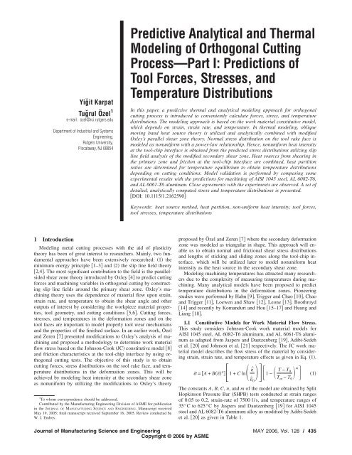
<strong>Predictive</strong> <strong>Analytical</strong> <strong>and</strong> <strong>Thermal</strong><br />
<strong>Modeling</strong> <strong>of</strong> <strong>Orthogonal</strong> <strong>Cutting</strong><br />
Process—Part I: Predictions <strong>of</strong><br />
Tool Forces, Stresses, <strong>and</strong><br />
Temperature Distributions<br />
In this paper, a predictive thermal <strong>and</strong> analytical modeling approach for orthogonal<br />
cutting process is introduced to conveniently calculate forces, stress, <strong>and</strong> temperature<br />
distributions. The modeling approach is based on the work material constitutive model,<br />
which depends on strain, strain rate, <strong>and</strong> temperature. In thermal modeling, oblique<br />
moving b<strong>and</strong> heat source theory is utilized <strong>and</strong> analytically combined with modified<br />
Oxley’s parallel shear zone theory. Normal stress distribution on the tool rake face is<br />
modeled as nonuniform with a power-law relationship. Hence, nonuniform heat intensity<br />
at the tool-chip interface is obtained from the predicted stress distributions utilizing slip<br />
line field analysis <strong>of</strong> the modified secondary shear zone. Heat sources from shearing in<br />
the primary zone <strong>and</strong> friction at the tool-chip interface are combined, heat partition<br />
ratios are determined for temperature equilibrium to obtain temperature distributions<br />
depending on cutting conditions. Model validation is performed by comparing some<br />
experimental results with the predictions for machining <strong>of</strong> AISI 1045 steel, AL 6082-T6,<br />
<strong>and</strong> AL 6061-T6 aluminum. Close agreements with the experiments are observed. A set <strong>of</strong><br />
detailed, analytically computed stress <strong>and</strong> temperature distributions is presented.<br />
DOI: 10.1115/1.2162590<br />
Keywords: heat source method, heat partition, non-uniform heat intensity, tool forces,<br />
tool stresses, temperature distributions<br />
proposed by Özel <strong>and</strong> Zeren 7 where the secondary deformation<br />
zone was modeled as triangular in shape. This approach will enable<br />
us to obtain normal <strong>and</strong> frictional shear stress distributions<br />
<strong>and</strong> lengths <strong>of</strong> sticking <strong>and</strong> sliding zones along the tool-chip interface,<br />
which will be utilized later to model nonuniform heat<br />
intensity as the heat source in the secondary shear zone.<br />
<strong>Modeling</strong> machining temperatures has attracted many researchers<br />
due to the complexity <strong>of</strong> measuring temperatures during machining.<br />
Many analytical models have been proposed to predict<br />
temperature distributions in the deformation zones. Pioneering<br />
studies were performed by Hahn 9, Trigger <strong>and</strong> Chao 10, Chao<br />
<strong>and</strong> Trigger 11, Loewen <strong>and</strong> Shaw 12, Leone 13, Boothroyd<br />
14 <strong>and</strong> recently by Kom<strong>and</strong>uri <strong>and</strong> Hou 15–17 <strong>and</strong> Huang <strong>and</strong><br />
Liang 18.<br />
1.1 Constitutive Models for Work Material Flow Stress.<br />
This study considers Johnson-Cook work material models for<br />
AISI 1045 steel, AL 6082-T6 aluminum, <strong>and</strong> AL 6061-T6 aluminum<br />
as adapted from Jaspers <strong>and</strong> Dautzenberg 19, Adibi-Sedeh<br />
et al. 20 <strong>and</strong> Johnson et al. 21 respectively. The JC work material<br />
model describes the flow stress <strong>of</strong> the material by considering<br />
strain, strain rate, <strong>and</strong> temperature effects as given in Eq. 1.<br />
¯ = A + B¯ n ¯˙<br />
1+C ln<br />
¯ ˙ 01− T − T m<br />
0<br />
Tm − T0 1<br />
The constants A, B, C, n, <strong>and</strong> m <strong>of</strong> the model are obtained by Split<br />
Hopkinson Pressure Bar SHPB tests conducted at strain ranges<br />
<strong>of</strong> 0.05 to 0.2, strain-rate <strong>of</strong> 7500 l/s, <strong>and</strong> temperature ranges <strong>of</strong><br />
35°C to 625°C by Jaspers <strong>and</strong> Dautzenberg 19 for AISI 1045<br />
steel <strong>and</strong> AL 6082-T6 aluminum alloy as modified by Adibi-Sedeh<br />
et al. 20 as given in Table 1.<br />
Journal <strong>of</strong> Manufacturing Science <strong>and</strong> Engineering MAY 2006, Vol. 128 / 435<br />
Copyright © 2006 by ASME
Table 1 Johnson-Cook material constants obtained from<br />
SHPB tests<br />
Material<br />
2 <strong>Thermal</strong> <strong>Modeling</strong> <strong>of</strong> the <strong>Cutting</strong> Process<br />
Temperature modeling <strong>of</strong> metal cutting is highly important<br />
since it directly affects the process variables such as the cutting<br />
forces <strong>and</strong> the contact length both <strong>of</strong> which are required to model<br />
wear mechanisms. The analytical modeling <strong>of</strong> steady state temperature<br />
in metal cutting presented by Hahn 9 is based on the<br />
heat source method <strong>of</strong> Jaeger 22. As shown in Fig. 1, the temperature<br />
rise T M under the effect <strong>of</strong> the oblique moving b<strong>and</strong><br />
uniform heat source with a velocity can be expressed as in<br />
Kom<strong>and</strong>uri <strong>and</strong> Hou 15.<br />
T MX,Z = q<br />
T m<br />
°C<br />
A<br />
MPa<br />
L<br />
e<br />
2il i =0<br />
−X−li sin /2ai K0 <br />
X − li sin <br />
2ai 2 + Z − li cos 2dli 2<br />
Kom<strong>and</strong>uri <strong>and</strong> Hou 16 modified the coordinate system <strong>of</strong><br />
Hahn’s solution for an oblique b<strong>and</strong> heat source in an infinite<br />
medium to simplify the derivation <strong>of</strong> equations for shear plane<br />
heat source qshear which is moving in a semi-infinite medium<br />
where the work surface <strong>and</strong> the chip surface are the boundaries <strong>of</strong><br />
a semi-infinite medium. However, since those boundaries were not<br />
considered in Hahn’s solution, an appropriate image heat source is<br />
added to the model as shown in Fig. 2.<br />
The temperature rise at any point MX,Z caused by the moving<br />
line heat source is due to the combined effect <strong>of</strong> the primary<br />
<strong>and</strong> image heat sources <strong>and</strong> can be calculated using Eq. 3.<br />
TMshearX,Z = q lAB shear<br />
e<br />
2cl i =0<br />
−X−li sin Vc /2ac B<br />
MPa C n m<br />
AISI 1045 26 1460 553.1 600.8 0.0134 0.234 1<br />
AL 6061-T6 21 582 324 114 0.002 0.42 1.34<br />
AL 6082-T6 20 582 250 243.6 0.00747 0.17 1.31<br />
K 0 Vc X − li sin <br />
2ac 2 + Z − li cos 2 + K0 Vc X − li sin <br />
2ac 2 + Z + li cos 2dli 3<br />
Fig. 1 Oblique moving b<strong>and</strong> heat source in an infinite medium<br />
Heat intensity at primary shear zone due to shearing can be modeled<br />
uniformly as<br />
q shear = F sV s<br />
l ABw<br />
Kom<strong>and</strong>uri <strong>and</strong> Hou 16 proposed that oblique b<strong>and</strong> heat source<br />
moving at chip velocity V c can be used to model temperature rise<br />
at any point on the chip, <strong>and</strong> oblique b<strong>and</strong> heat source moving at<br />
cutting velocity V can be used to model temperature rise at any<br />
point in the workpiece due to primary heat source. In this study, it<br />
is assumed that all <strong>of</strong> the deformation energy caused by shearing<br />
in primary shear zone is converted into heat.<br />
The effect <strong>of</strong> secondary heat source is modeled by considering<br />
tool-chip interaction. Chao <strong>and</strong> Trigger 11 assumed uniform heat<br />
intensity with nonuniform heat partition ratio at the tool-chip interface,<br />
<strong>and</strong> they used the functional analysis method to find a<br />
temperature distribution along the tool-chip interface. Kom<strong>and</strong>uri<br />
<strong>and</strong> Hou 16 extended the functional analysis based on the work<br />
<strong>of</strong> Chao <strong>and</strong> Trigger. However, because <strong>of</strong> the presence <strong>of</strong> plastic<br />
<strong>and</strong> elastic zones along contact length, secondary heat source cannot<br />
be assumed as uniform. Recently, Huang <strong>and</strong> Liang 18 used<br />
the nonuniform heat intensity along tool-chip interface in their<br />
model by converting uniform shear stress distribution to an assumed<br />
shear stress distribution without calculating the actual<br />
length <strong>of</strong> sticking zone, but by using recommended values from<br />
other studies.<br />
Figure 3a shows the heat transfer model <strong>of</strong> the frictional heat<br />
source at the tool-chip interface on the chip side. The interface<br />
frictional heat source relative to the chip is a b<strong>and</strong> heat source<br />
moving with velocity V c. Considering the heat partition fraction<br />
for the chip Bx, the heat liberation rate Bxq plx <strong>of</strong> the movingb<strong>and</strong><br />
heat source is considered to be transferred into the chip.<br />
Since the chip thickness t c is small, the boundary effect <strong>of</strong> the<br />
upper surface <strong>of</strong> the chip can be taken into account by adding an<br />
image heat source. The upper surface boundary <strong>of</strong> the chip is<br />
considered to be adiabatic. The temperature rise at any point<br />
Fig. 2 Modified Hahn’s model for an oblique b<strong>and</strong> heat source in a semi-infinite medium<br />
436 / Vol. 128, MAY 2006 Transactions <strong>of</strong> the ASME<br />
4
Fig. 3 Heat transfer model for the frictional heat source at the<br />
tool-chip interface „a… on the chip side as a moving b<strong>and</strong> heat<br />
source „b… on the tool side as a stationary rectangular heat<br />
source<br />
MX,Z in the chip side is caused by the frictional moving heat<br />
source <strong>and</strong> its image heat source can be found as<br />
T Mchip-friction X,Z = 1<br />
lc Bliqpllie cl i =0<br />
−X−liVc /2ac K 0R i<br />
Vc + K0Ri 2ac Vc i<br />
2acdl Figure 3b shows the heat transfer model <strong>of</strong> the frictional heat<br />
source at the tool-chip interface on the tool side. The interface<br />
frictional heat source relative to the tool is a stationary rectangular<br />
heat source. The tool clearance face is considered to be adiabatic.<br />
Considering the heat partition fraction for the chip 1−Bx, the<br />
heat liberation rate 1−Bx q plx <strong>of</strong> the heat source is considered<br />
to be transferred into the tool. The temperature rise at any<br />
point MX,Y ,Z in the tool caused by the frictional stationary heat<br />
source including its image heat source, given as<br />
5<br />
Fig. 4 Common coordinate system for combined effect heat<br />
sources<br />
T Mtool-friction X,Z = 1<br />
w/2<br />
l c<br />
x 2ty i =−w/2 i =0<br />
1<br />
+<br />
Ri 1<br />
idyi Ridx 1−Bx iq plx i<br />
In order to find the temperature rise in the tool caused by the shear<br />
plane heat source, heat coming from the shear plane heat source<br />
can be modeled as an induced stationary heat source located at the<br />
tool-chip interface. For the induced heat source, Eq. 6 can be<br />
used with some modifications where initially the heat intensity <strong>of</strong><br />
the induced heat source is unknown but the average temperature<br />
rise caused by it at the tool-chip interface is known. The latter is<br />
obtained during the calculation <strong>of</strong> the temperature rise distribution<br />
in the chip at the tool-chip interface on the chip side as detailed in<br />
Eq. 5. Due to continuity <strong>of</strong> the heat flow, the temperature rise<br />
distribution at the tool-chip interface on the tool side is the same<br />
as that on the chip side. Therefore, the average heat liberation<br />
intensity <strong>of</strong> the induced heat source <strong>and</strong> heat partition ratios along<br />
tool-chip interface can be calculated. By using the information <strong>of</strong><br />
average temperature equality at the interface, induced heat intensity<br />
<strong>of</strong> shear plane heat source can be calculated.<br />
Using the above equations by considering z=0 <strong>and</strong> y=0, the<br />
local temperature rise at each point along the tool-chip interface<br />
can be calculated. Since the average temperature rise on both<br />
sides at the contacting interface should be the same, the distribution<br />
<strong>of</strong> the heat partition ratio can be calculated either numerically<br />
by satisfying Eq. 7 along every point on tool-chip interface or by<br />
assuming an expression for heat partition ratio <strong>and</strong> calculating the<br />
parameters <strong>of</strong> this expression by matching the temperature distribution<br />
curves on the tool <strong>and</strong> chip sides as in Kom<strong>and</strong>uri <strong>and</strong> Hou<br />
16.<br />
TMshearX,0 + TMchip-frictionX,0 = TMtool-frictionX,0,0 + TMinduced-shearX,0,0 7<br />
In order to ease application a common coordinate system should<br />
be chosen. The common coordinate system for the combined effect<br />
<strong>of</strong> primary <strong>and</strong> secondary heat sources is given in Fig. 4.<br />
Nonlinear heat intensity <strong>of</strong> the secondary heat source, which is<br />
dependent on shear stress distribution on the tool-chip interface,<br />
will be calculated analytically. This approach is the refinement on<br />
the Kom<strong>and</strong>uri <strong>and</strong> Hou 16 model in this study. Calculation <strong>of</strong><br />
the shear stress distribution <strong>and</strong> the lengths <strong>of</strong> sticking <strong>and</strong> sliding<br />
zones, shown in Fig. 5, will be explained next.<br />
Therefore, with the calculated heat partition ratios, the temperature<br />
rise at any point in the chip can be calculated with Eq. 8.<br />
Journal <strong>of</strong> Manufacturing Science <strong>and</strong> Engineering MAY 2006, Vol. 128 / 437<br />
6
Fig. 5 Heat intensity model along the rake face <strong>of</strong> the tool<br />
TMchipX,Z = TMshearX,Z + TMchip-frictionX,Z + T0 8<br />
The temperature rise at any given point in the tool can be calculated<br />
by<br />
TMtoolX,0,Z = TMtool-frictionX,0,Z + TMinduced-shearX,0,Z + T0 3 <strong>Analytical</strong> <strong>Modeling</strong> <strong>of</strong> the <strong>Cutting</strong> Process<br />
A simplified illustration based on experimental observations <strong>of</strong><br />
the plastic deformation for the formation <strong>of</strong> a continuous chip<br />
when machining a ductile material is given in Fig. 6. Oxley 4<br />
assumed that the primary zone is a parallel-sided shear zone <strong>and</strong><br />
the secondary deformation zone adjacent to the tool-chip interface<br />
is caused by the intense contact pressure <strong>and</strong> frictional force,<br />
which causes further plastic deformation.<br />
Based on Oxley’s model, the average value <strong>of</strong> the shear strain<br />
rate along AB is<br />
VS ˙ AB = C0 lAB The shear velocity Vs along the shear plane is<br />
Fig. 6 Simplified deformation zones in orthogonal cutting<br />
9<br />
10<br />
V cos <br />
VS = 11<br />
cos − <br />
Given by Eq. 12, lAB is the length <strong>of</strong> primary zone AB, <strong>and</strong> can<br />
be calculated from geometry as<br />
tu lAB =<br />
12<br />
sin<br />
<strong>and</strong> C0 is a constant representing the ratio <strong>of</strong> the thickness <strong>of</strong> the<br />
primary zone to the length <strong>of</strong> plane AB. Cut chip thickness can be<br />
estimated from Eq. 13 for a given shear angle as<br />
tc = tu cos − <br />
13<br />
sin<br />
<strong>and</strong> the strain in the middle <strong>of</strong> the primary shear zone is given as<br />
cos <br />
¯ AB =<br />
14<br />
23 sin cos − <br />
In the primary zone, the flow stress on plane AB can be calculated<br />
by using Eq. 1 <strong>and</strong> the average value <strong>of</strong> shear stress at AB<br />
according to the Von Mises criterion can be calculated as<br />
k AB = AB/3 15<br />
The shear force along AB may be calculated as<br />
F s = k ABt uw<br />
sin <br />
The hydrostatic pressures at A <strong>and</strong> B are<br />
16<br />
p A = k AB1+2 <br />
4 − 17<br />
pB = kAB2 tan −1+2 − 18<br />
4<br />
The angle between the resultant force <strong>and</strong> the direction <strong>of</strong> the<br />
primary shear zone can be obtained using the known pressure<br />
distribution <strong>and</strong> shear stress along the shear plane.<br />
= tan−11+2· dk C0AB − − 19<br />
4 d kAB where<br />
dk k k T k ˙<br />
= + +<br />
d T ˙ <br />
<strong>and</strong> after necessary differentiations<br />
m<br />
Tm − T0 dk 1<br />
=<br />
d 3 Bn n−1 ˙ AB<br />
AB 1+C ln 1−<br />
˙ 0 TAB − T0 n ˙ AB<br />
+ BAB1+C ln ˙ 0<br />
<br />
− m<br />
T m − T 0 T AB − T 0<br />
+ 1<br />
3 A<br />
m−1<br />
Tm − T0 20<br />
T<br />
<br />
21<br />
In Eq. 21 the derivation T/ should be computed numerically.<br />
The constant C 0 can be found by using the relation given in Eq.<br />
22 20<br />
C0 = pA − pB 22<br />
ku − kl where ku is the shear stress at upper boundary EF in Fig. 6 <strong>and</strong><br />
kl shear stress at lower boundary CD in Fig. 6 <strong>of</strong> the primary<br />
shear zone. In order to find ku, strain at EF can be approximated<br />
by Eq. 23 <strong>and</strong> strain rate can be assumed to be constant all along<br />
the primary shear zone 20,<br />
438 / Vol. 128, MAY 2006 Transactions <strong>of</strong> the ASME
Fig. 7 Forces acting on the shear plane <strong>and</strong> the tool with resultant<br />
stress distributions on the tool rake face<br />
EF =2AB 23<br />
<strong>and</strong> TEF can be calculated analytically from its coordinates in the<br />
chip. Forces acting on the shear plane <strong>and</strong> the tool with assumed<br />
resultant stress distributions on the tool rake face are given in<br />
Fig. 7.<br />
The distance between point B <strong>and</strong> the point where R cuts the<br />
shear the plane Xsh can be found by taking moments about the<br />
cutting edge <strong>of</strong> the normal stresses on the shear plane AB<br />
Xsh = lAB2pA + pB 24<br />
3pA + pB <strong>and</strong> the distance from the cutting edge to the point where the<br />
resultant force R intersects the tool cutting face Xfr can be found<br />
from geometry as given in Li 21<br />
Fig. 8 Flow chart for computing average temperatures<br />
Fig. 9 Flow chart <strong>of</strong> the computational algorithm<br />
sin <br />
Xfr =<br />
sin <br />
2 + − + Xsh 25<br />
The normal F N <strong>and</strong> tangential F components <strong>of</strong> the resultant<br />
cutting force R on the tool rake face, cutting force F c <strong>and</strong> thrust<br />
force F t can be obtained<br />
F N = R · cos − + , F = R · sin − + <br />
26<br />
Fc = R · cos − , Ft = R · sin − <br />
Interfacial friction on the tool rake face is not continuous <strong>and</strong> is a<br />
function <strong>of</strong> the normal <strong>and</strong> frictional stress distributions. According<br />
to Zorev 3, the normal stress is greatest at the tool tip <strong>and</strong><br />
gradually decreases to zero at the point where the chip separates<br />
from the rake face as shown in Fig. 7. The frictional shearing<br />
Journal <strong>of</strong> Manufacturing Science <strong>and</strong> Engineering MAY 2006, Vol. 128 / 439
Table 2 <strong>Cutting</strong> conditions for AISI 1045 steel „w=2…†24‡<br />
Test V m/min deg t u mm t c mm a<br />
stress distribution is more complicated. Over the portion <strong>of</strong> the<br />
tool-chip contact area near the cutting edge, sticking friction occurs,<br />
<strong>and</strong> the frictional shearing stress int is equal to the average<br />
shear flow stress at tool-chip interface in the chip kchip. Over the<br />
remainder <strong>of</strong> the tool-chip contact area, sliding friction occurs,<br />
<strong>and</strong> the frictional shearing stress can be calculated using the coefficient<br />
<strong>of</strong> friction e. The normal stress distribution on the tool<br />
rake face can be described by<br />
Nx = Nmax1− x a<br />
lc 27<br />
where Nmax is given by Oxley 4 as<br />
Nmax = p B +2k AB − 28<br />
Unknowns in Eq. 27 are lc <strong>and</strong> a, which require two equations to<br />
solve. Integrating the normal stress along the entire tool-chip contact<br />
length yields the relation in Eq. 29, which is equal to normal<br />
force on the tool rake face<br />
lc lc FN =0<br />
wNxdx =0<br />
wNmax1− x a<br />
dx 29<br />
lc Also taking the moment according to point B<br />
F NX fr =0<br />
<strong>and</strong> denoting<br />
l c<br />
w Nxxdx =0<br />
l c<br />
I = N max X frw<br />
F N<br />
wNmax1− x a<br />
xdx 30<br />
lc 31<br />
From Eqs. 29 <strong>and</strong> 30, the contact length along the tool-chip<br />
interface l c <strong>and</strong> the exponent a can be obtained as<br />
a =−1+ 16I 2 −8I<br />
4I −2<br />
deg a<br />
1 200 −7 0.150 0.33 22<br />
2 200 +5 0.150 0.33 25<br />
3 200 −7 0.300 0.6 24<br />
4 200 +5 0.300 0.6 27<br />
5 300 −7 0.150 0.31 24<br />
6 300 +5 0.150 0.31 26<br />
7 300 −7 0.300 0.58 25<br />
8 300 +5 0.300 0.56 29<br />
a As predicted with the model.<br />
32<br />
Table 3 Force <strong>and</strong> temperature predictions for AISI 1045 steel<br />
Test<br />
Predicted<br />
F C N<br />
Predicted<br />
F T N<br />
Predicted<br />
T AB<br />
Predicted<br />
max T int<br />
Measured 23<br />
max T int<br />
1 662 466 370 1080 1120<br />
2 596 324 332 1125 1250<br />
3 1206 728 369 1170 1100<br />
4 1097 509 319 1158 1220<br />
5 613 371 370 1241 1310<br />
6 576 288 330 1227 1300<br />
7 1174 671 365 1329 1305<br />
8 1046 430 311 1310 1300<br />
Fig. 10 Comparison <strong>of</strong> the predictions <strong>of</strong> the cutting force „a…,<br />
<strong>and</strong> thrust force „b… with experimental data from †23‡<br />
lc = FN . a +1<br />
33<br />
awNmax The shear stress distribution on the tool rake face illustrated in<br />
Fig. 7 can be represented in two distinct regions: a in the sticking<br />
region intx=k chip <strong>and</strong> when eNxk chip, 0xlP, b<br />
in the sliding region intx= eNx <strong>and</strong> when eNx kchip, lPxl c. Here int is the shear stress <strong>of</strong> the material at<br />
the tool-chip interface, <strong>and</strong> it is related to the frictional force<br />
between the chip <strong>and</strong> the tool, FF,as Table 4 Predicted normal stress distribution parameters for<br />
machining AISI 1045 steel<br />
Test Nmax N/mm 2 l p mm l c mm a<br />
1 1380 0.12 0.6 0.75<br />
2 992 0.11 0.54 1.1<br />
3 1305 0.13 1.04 0.89<br />
4 1007 0.28 0.91 1.3<br />
5 1308 0.07 0.52 0.9<br />
6 970 0.11 0.56 1.3<br />
7 1325 0.14 0.98 0.91<br />
8 1039 0.28 0.82 1.4<br />
440 / Vol. 128, MAY 2006 Transactions <strong>of</strong> the ASME
Fig. 11 Predicted stress distributions on the tool rake face for<br />
machining AISI 1045 steel<br />
lP lC FF =0<br />
wintdx +l P<br />
w e Nxdx 34<br />
The relation between the average coefficient <strong>of</strong> friction in the<br />
sliding region e <strong>and</strong> int is also given in<br />
e = int<br />
Nl P<br />
35<br />
Combining Eqs. 36 <strong>and</strong> 37 leads to the expression for int as<br />
shown in<br />
int =<br />
F F<br />
wlP + w<br />
lC Nxdx NlPl p<br />
The chip velocity can be calculated as<br />
36<br />
Fig. 12 Temperature distributions for AISI 1045 at conditions<br />
in test 1. „The figure is drawn perpendicular to the tool-chip<br />
interface for simplicity; the figure should be rotated 7 deg<br />
clockwise for actual view.…<br />
Fig. 13 Temperatures along the tool-chip interface for test<br />
condition 1 for AISI 1045<br />
V sin <br />
Vc = 37<br />
cos − <br />
According to Oxley 4, the average shear strain rate <strong>and</strong> shear<br />
strain are considered constant <strong>and</strong> can be estimated from Eqs. 38<br />
<strong>and</strong> 39 in the secondary zone.<br />
l P =<br />
˙ int = V c<br />
· t c<br />
int = l P<br />
· t c<br />
· t c<br />
sin − <br />
38<br />
39<br />
40<br />
The flow stress at tool chip interface k chip can be found by utilizing<br />
Eq. 1<br />
kchip = 1<br />
3 A + B¯n ¯˙<br />
1+C ln<br />
¯ ˙ 01− Tint − T<br />
stiction 0<br />
Tm − T0 m<br />
<br />
<br />
41<br />
Fig. 14 Heat partition ratio along the tool chip interface for<br />
test condition 1 for AISI 1045<br />
Journal <strong>of</strong> Manufacturing Science <strong>and</strong> Engineering MAY 2006, Vol. 128 / 441
Test<br />
Table 5 <strong>Cutting</strong> conditions <strong>and</strong> predictions <strong>of</strong> force <strong>and</strong> temperatures for machining Al6082-T6 „=8 deg, w=3 mm…<br />
4 Solution <strong>of</strong> the Combined <strong>Thermal</strong> <strong>and</strong> <strong>Analytical</strong><br />
<strong>Modeling</strong> <strong>of</strong> the <strong>Cutting</strong> Process<br />
For the proposed orthogonal machining model, cutting conditions,<br />
<strong>and</strong> the material properties <strong>of</strong> the workpiece are the inputs.<br />
The outputs are process related variables, such as shear angle,<br />
contact length, cutting forces, tool stress distributions, <strong>and</strong> temperature<br />
distribution in the chip <strong>and</strong> along the tool-chip interface.<br />
The shear angle, strain rate constant, <strong>and</strong> the ratio <strong>of</strong> thickness <strong>of</strong><br />
the tool-chip interface plastic zone to chip thickness are selected<br />
based on the minimum force principle. As discussed above, the<br />
temperature rise along shear zone X,Z can be calculated as<br />
given in Eq. 3. The average temperature in primary shear zone<br />
can be found by integrating Eq. 3 along the shear length, given<br />
as<br />
T AB =<br />
0<br />
l AB<br />
T Mshear X,Zdl i<br />
l AB<br />
+ T 0<br />
42<br />
The heat partition ratio expression BX is adopted from<br />
Kom<strong>and</strong>uri <strong>and</strong> Hou 16 <strong>and</strong> given in<br />
Bx = Bchip − B1 +2B1 x<br />
m1 lc 1−Bx = Btool + B1 −2B1 x<br />
m1 lc 43<br />
In this expression, the coefficients B chip, B 1, <strong>and</strong> m i should be<br />
calculated by matching the temperature distribution curves as<br />
much as possible along the tool-chip interface. The discussions<br />
about this expression are given in Kom<strong>and</strong>uri <strong>and</strong> Hou 16. Once<br />
the Bx expression is calculated, the average temperature on the<br />
tool chip interface can be found as<br />
T int =<br />
V<br />
m/min<br />
0<br />
l c<br />
t u<br />
mm<br />
T Mshear X,0 + T Mchip-friction X,0,0dl i<br />
l c<br />
t c<br />
mm<br />
<br />
deg<br />
+ T 0<br />
44<br />
The thermal conductivity c <strong>and</strong> thermal diffusivity a c coefficients<br />
<strong>of</strong> the workpiece are considered to be constant in the thermal<br />
model, but in fact they depend on temperature. An iterative<br />
approach is used in calculation <strong>of</strong> the temperatures. For example,<br />
an average temperature for the primary shear zone is predicted,<br />
thermal conductivity <strong>and</strong> diffusivity at that predicted average temperature<br />
are found <strong>and</strong> actual average temperature is calculated by<br />
F C<br />
N<br />
Predicted Measured 20<br />
1 120 0.2 0.52 21.7 550 405 217 498 210 552 384<br />
2 240 0.4 0.76 29.2 767 273 221 464 205 795 300<br />
3 360 0.2 0.44 25.2 443 221 228 493 188 456 204<br />
4 360 0.4 0.64 33.8 719 223 214 508 198 768 276<br />
Table 6 Other predictions for Al6082-T6 „=8 deg, w=3 mm…<br />
Test Nmax N/mm 2 l p mm l c mm a<br />
F T<br />
N<br />
T AB<br />
°C<br />
T int<br />
°C<br />
T AB<br />
°C<br />
F C<br />
N<br />
F T<br />
N<br />
using these constants. The iteration continues until the predicted<br />
<strong>and</strong> average temperature calculations are close, as shown in the<br />
flow chart given in Fig. 8. <strong>Thermal</strong> conductivity <strong>of</strong> the carbide<br />
tool is taken constant as 0.4 J/cm s°C.<br />
The shear angle is determined according to the fact that the<br />
tool-chip interface shear stress int caused by the resultant cutting<br />
force for a given set <strong>of</strong> cutting conditions must be equal to the<br />
chip material flow stress k chip at the sticking region, which is the<br />
function <strong>of</strong> strain, strain rate, <strong>and</strong> temperature at the interface for<br />
the same cutting condition. Since heat intensity is required to<br />
obtain temperature distribution in the primary shear zone, shear<br />
force is found through trial <strong>and</strong> error until assumed <strong>and</strong> calculated<br />
shear forces are identical. The search for the true value <strong>of</strong> will<br />
go through iterations until the calculated interface shear stress <strong>and</strong><br />
the material shear flow stress are equal. If there is more than one<br />
shear angle that satisfies the above condition, the highest angle is<br />
chosen. Reasonable values <strong>of</strong> C 0 <strong>and</strong> are also searched iteratively<br />
at the same time to simultaneously satisfy the conditions.<br />
The flow chart <strong>of</strong> this approach is summarized in Fig. 9.<br />
5 Model Validation <strong>and</strong> Results<br />
In order to validate the predictive thermal <strong>and</strong> analytical modeling<br />
approach for metal cutting processes presented in this paper,<br />
a set <strong>of</strong> orthogonal cutting experiments for machining AISI 1045<br />
steel 23, AL 6082-T6 aluminum alloy 20,24, <strong>and</strong> AL6061-T6<br />
aluminum alloy 20 is utilized. Experimental data include measured<br />
cutting <strong>and</strong> thrust forces <strong>and</strong> average temperatures on the<br />
shear plane <strong>and</strong> at the tool-chip interface.<br />
5.1 Model Validation for Steel Machining. The cutting conditions<br />
for machining AISI 1045 are given in Table 2. In these<br />
cutting conditions, machining with both a negative −7 deg <strong>and</strong> a<br />
1 420.8 0.35 1.1 0.542<br />
2 322.3 0.45 0.935 1.11<br />
3 315.2 0.31 0.67 1.76<br />
4 436 0.23 0.92 1.28 Fig. 15 Temperature distributions in the chip for Al 6082-T6 at<br />
conditions in test 2<br />
442 / Vol. 128, MAY 2006 Transactions <strong>of</strong> the ASME
Test<br />
Table 7 <strong>Cutting</strong> conditions <strong>and</strong> predictions <strong>of</strong> force <strong>and</strong> temperatures for machining Al6061-T6 „=8 deg, w=3.3 mm…<br />
V<br />
m/min<br />
t u<br />
mm<br />
t c<br />
mm<br />
<br />
deg<br />
positive rake 5 deg angle were tested. Chip thickness <strong>and</strong> shear<br />
angle were calculated as presented in Table 2. The predicted temperatures<br />
are compared with experimental values in Table 3. The<br />
predicted forces are compared with the experiments for machining<br />
AISI 1045 steel as shown in Fig. 10. The comparison with the<br />
measured forces shows that the force predictions are in close<br />
agreement. The measured temperatures <strong>and</strong> the predicted temperatures<br />
at the tool-chip interface in machining <strong>of</strong> AISI 1045 steel<br />
indicate agreements for Tests 1, 2, <strong>and</strong> 4. However, more refined<br />
measurements <strong>of</strong> temperature distributions during the cutting process<br />
are needed to validate predicted temperature distributions <strong>and</strong><br />
heat partitions. Such measurements for machining <strong>of</strong> AISI 1045<br />
steel were performed by Davies et al. 25. Figure 10 shows the<br />
cutting <strong>and</strong> thrust force predictions <strong>of</strong> the proposed model under<br />
AMM test 23 conditions. For the cases presented, the predicted<br />
forces are in good agreement with the experimental values <strong>and</strong><br />
always remain within upper <strong>and</strong> lower limits 27,28.<br />
In addition, the predictions for normal stress distribution on the<br />
tool rake face for machining AISI 1045 steel are given in Table 4<br />
<strong>and</strong> Fig. 11. The predicted normal stress distributions depict that<br />
the power law exponent a is less than 1 for machining at negative<br />
rake angles <strong>and</strong> greater than 1 for machining at positive rake<br />
F C<br />
N<br />
Predicted Measured 20<br />
1 165 0.16 0.44 20.6 470 383 184 443 0.45 475 388<br />
2 225 0.16 0.41 22 430 311 190 453 0.4 450 315<br />
3 165 0.32 0.8 22.6 821 572 199 485 0.7 825 545<br />
4 225 0.32 0.75 24 762 475 202 503 0.78 785 415<br />
Table 8 Other predictions for Al6061-T6 „=8 deg, w<br />
=3.3 mm…<br />
Test Nmax N/mm 2 l p mm l c mm a<br />
1 412.6 0.5 1.0 0.43<br />
2 378.3 0.42 0.85 0.55<br />
3 366 0.82 1.62 0.6<br />
4 348 0.7 1.4 0.73<br />
Fig. 16 Temperature distributions in the chip for Al 6061-T6 at<br />
conditions in test 3<br />
F T<br />
N<br />
T AB<br />
°C<br />
T int<br />
°C<br />
t c<br />
mm<br />
F C<br />
N<br />
F T<br />
N<br />
angles. This behavior affects temperature predictions since nonuniform<br />
heat partition at the tool-chip interface is obtained from<br />
normal stress distributions on the tool rake face.<br />
The temperature distributions in the tool, chip, <strong>and</strong> workpiece<br />
can be obtained by dividing the tool, chip, <strong>and</strong> workpiece into<br />
small increments <strong>and</strong> calculating the temperature rise at every<br />
point. Figure 12 shows the temperature distributions in the chip,<br />
tool <strong>and</strong> workpiece.<br />
The nonuniform heat partition distribution at the tool-chip interface<br />
is given in Fig. 13 <strong>and</strong> variation <strong>of</strong> heat partition ratio is<br />
shown in Fig. 14. When uniform heat intensity is used in thermal<br />
modeling maximum temperature is obtained close to the end <strong>of</strong><br />
the tool-chip interface. Due to nonlinear heat intensity modeling,<br />
where the length <strong>of</strong> the sticking zone is considered, the location <strong>of</strong><br />
maximum temperature gets closer to the middle <strong>of</strong> the tool chip<br />
interface. The temperature rise distribution along the tool-chip interface<br />
for chip <strong>and</strong> tool side is shown in Fig. 13. The discrepancy<br />
between temperature rise curves can be reduced by using a heat<br />
partition expression, which has higher power terms.<br />
5.2 Model Validation for Aluminum Machining. The cutting<br />
conditions for machining AL6082-T6 that are adapted from<br />
Adibi-Sedeh et al. 20 <strong>and</strong> Jaspers <strong>and</strong> Dautzenberg 24 are<br />
given in Table 5. The predicted forces, temperatures <strong>and</strong> parameters<br />
<strong>of</strong> normal stress distributions are presented in Tables 5 <strong>and</strong> 6<br />
for machining AL6082-T6. The temperature distributions in the<br />
chip, tool, <strong>and</strong> workpiece for AL-6082-T6 test 2 are given in<br />
Fig. 15.<br />
The model validation is also performed on machining<br />
AL6061-T6 aluminum alloy. The cutting conditions for machining<br />
AL6061-T6 that are adapted from Adibi-Sedeh et al. 20 are<br />
given in Table 7. The predicted forces, temperatures, <strong>and</strong> parameters<br />
<strong>of</strong> normal stress distributions are presented in Tables 7 <strong>and</strong> 8<br />
for machining AL6082-T6. The temperature distributions in the<br />
chip, tool <strong>and</strong> workpiece for AL-6082-T6 test 3 are given in<br />
Fig. 16.<br />
6 Conclusion<br />
This paper combines oblique moving b<strong>and</strong> heat source theory<br />
with nonuniform heat intensity at tool-chip interface <strong>and</strong> modified<br />
Oxley’s parallel shear zone theory to predict cutting forces, stress,<br />
<strong>and</strong> temperature distributions. The proposed methodology has<br />
been applied to two different materials, <strong>and</strong> promising results in<br />
close agreement with experimental results have been obtained. As<br />
a major contribution, the methodology proposed here predicts detailed<br />
temperature distributions for machining <strong>of</strong> AISI 1045 steel,<br />
AL-6082-T6, <strong>and</strong> AL 6061-T6, aluminum alloys as shown in Figs.<br />
12, 15, <strong>and</strong> 16. The model provides significant advantages from<br />
the tool wear modeling point <strong>of</strong> view.<br />
Acknowledgment<br />
This research is supported by the Rutgers University Research<br />
Council Grants program under the Grant No. 2-02321.<br />
Journal <strong>of</strong> Manufacturing Science <strong>and</strong> Engineering MAY 2006, Vol. 128 / 443
Nomenclature<br />
A plastic equivalent strain in Johnson-Cook constitutive<br />
model MPa<br />
a power exponent <strong>of</strong> the normal stress distribution<br />
on the tool rake face<br />
ai thermal diffusivity <strong>of</strong> the medium i<br />
B strain related constant in Johnson-Cook constitutive<br />
model MPa<br />
Bx heat partition fraction<br />
C strain-rate sensitivity constant in Johnson-Cook<br />
constitutive model<br />
C0 strain rate constant proposed by Oxley<br />
FC,F T cutting <strong>and</strong> thrust force components N<br />
FF,F N frictional <strong>and</strong> normal force components at tool<br />
rake face N<br />
FS,F NS shear force <strong>and</strong> normal to the shear force components<br />
at AB N<br />
K0 zero order Bessel function <strong>of</strong> the second kind<br />
kAB shear flow stress on AB N/mm2 kchip shear flow stress in chip at tool-chip interface<br />
N/mm2 lAB length <strong>of</strong> the primary shear zone mm<br />
lc length <strong>of</strong> tool-chip contact mm<br />
lp length <strong>of</strong> sticking region mm<br />
m thermal s<strong>of</strong>tening parameter in Johnson-Cook<br />
constitutive model<br />
n strain-hardening parameter in Johnson-Cook<br />
constitutive model<br />
pA, pB, pM , pN hydrostatic stresses at the points A, B, M, <strong>and</strong><br />
N N/mm2 q heat intensity<br />
T0 initial work material temperature °C<br />
TAB average temperature along AB °C<br />
Tint average temperature along tool-chip interface<br />
°C<br />
Tm melting temperature <strong>of</strong> the work material °C<br />
tu,t c undeformed <strong>and</strong> deformed chip thickness mm<br />
V,V S,V C cutting velocity, shear velocity, <strong>and</strong> chip velocity<br />
m/sec<br />
w width <strong>of</strong> cut mm<br />
tool rake angle degree<br />
proportion <strong>of</strong> the thickness <strong>of</strong> the secondary<br />
zone to the chip thickness<br />
¯ AB,¯ int effective strain at AB <strong>and</strong> tool-chip interface<br />
mm/mm<br />
¯ ˙ 0 reference strain rate s−1 ¯ ˙ AB,¯ ˙ int effective strain rate at AB <strong>and</strong> tool-chip interface<br />
s−1 shear angle deg<br />
¯ AB,¯ int effective shear strain at AB <strong>and</strong> tool-chip interface<br />
mm/mm<br />
¯ ˙ AB,¯ ˙ int effective shear strain-rate at AB <strong>and</strong> tool-chip<br />
interface s −1 <br />
e coefficient <strong>of</strong> friction in the elastic contact region<br />
<strong>of</strong> tool-chip interface<br />
density kg/m 3 <br />
¯ AB effective flow stress at AB N/mm 2 <br />
N normal stresses acting on tool-chip interface<br />
N/mm 2 <br />
int frictional shear stress at tool-chip interface<br />
N/mm 2 <br />
thermal conductivity W/m°C<br />
References<br />
1 Ernst, H., <strong>and</strong> Merchant, M. E., 1941, “Chip Formation, Friction <strong>and</strong> High<br />
Quality Machined Surfaces,” Trans. Am. Soc. Met., 29, pp. 299–378.<br />
2 Lee, E. H., <strong>and</strong> Shaffer, B. W., 1951, “The Theory <strong>of</strong> Plasticity Applied to a<br />
Problem <strong>of</strong> Machining,” J. Appl. Mech., 18, pp. 405–413.<br />
3 Zorev, N. N., 1963, “Inter-Relationship Between Shear Processes Occurring<br />
Along Tool Face <strong>and</strong> Shear Plane in Metal <strong>Cutting</strong>,” International Research in<br />
Production Engineering ASME, New York, pp. 42–49.<br />
4 Oxley, P. L. B., 1989, Mechanics <strong>of</strong> Machining, an <strong>Analytical</strong> Approach to<br />
Assessing Machinability, Ellis Horwood Limited, Chichester, Engl<strong>and</strong>.<br />
5 Childs, T. H. C., 1998, “Material Property Needs in <strong>Modeling</strong> Metal Machining,”<br />
Proceedings <strong>of</strong> the CIRP International Workshop on <strong>Modeling</strong> <strong>of</strong> Machining<br />
Operations, Atlanta, Georgia, I. S. Jawahir, A. K. Balaji, <strong>and</strong> R.<br />
Stevenson, eds., University <strong>of</strong> Kentucky Publishing Services, Lexington, KY,<br />
May 19, pp. 193–202.<br />
6 Özel, T., <strong>and</strong> Altan, T., 2000, “Determination <strong>of</strong> Workpiece Flow Stress <strong>and</strong><br />
Friction at the Chip-Tool Contact for High-Speed <strong>Cutting</strong>,” Int. J. Mach. Tools<br />
Manuf., 401, pp. 133–152.<br />
7 Özel, T., <strong>and</strong> Zeren, E., 2005, “A Methodology to Determine Work Material<br />
Flow Stress <strong>and</strong> Tool-Chip Interfacial Friction Properties by Using Analysis <strong>of</strong><br />
Machining,” ASME J. Manuf. Sci. Eng., in press.<br />
8 Johnson, G. R., <strong>and</strong> Cook, W. H., 1983, “A Constitutive Model <strong>and</strong> Data for<br />
Metals Subjected to Large Strains, High Strain Rates <strong>and</strong> High Temperatures,”<br />
Proceedings <strong>of</strong> the 7th International Symposium on Ballistics, The Hague, The<br />
Netherl<strong>and</strong>s, April 21–26, pp. 541–547.<br />
9 Hahn, R. S., 1951, “On the Temperature Developed at the Shear Plane in the<br />
Metal <strong>Cutting</strong> Process,” Proceedings <strong>of</strong> First US National Congress <strong>of</strong> Applied<br />
Mechanics, pp. 661–666.<br />
10 Trigger, K. J., <strong>and</strong> Chao, B. T., 1951, “An <strong>Analytical</strong> Evaluation <strong>of</strong> Metal<br />
<strong>Cutting</strong> Temperatures,” Trans. ASME, 73, pp. 57–68.<br />
11 Chao, B. T., <strong>and</strong> Trigger, K. J., 1953, “The Significance <strong>of</strong> the <strong>Thermal</strong> Number<br />
in Metal Machining,” Trans. ASME, 75, pp. 109–120.<br />
12 Leowen, E. G., <strong>and</strong> Shaw, M. C., 1954, “On the Analysis <strong>of</strong> <strong>Cutting</strong> Tool<br />
Temperatures,” Trans. ASME, 71, pp. 217–231.<br />
13 Leone, W. C., 1954, “Distribution <strong>of</strong> Shear Zone Heat in Metal <strong>Cutting</strong>,”<br />
Trans. ASME, 76, pp. 121–125.<br />
14 Boothroyd, G., 1963, “Temperatures in <strong>Orthogonal</strong> Metal <strong>Cutting</strong>,” Proc. Inst.<br />
Mech. Eng., 177, pp. 789–810.<br />
15 Kom<strong>and</strong>uri, R., <strong>and</strong> Hou, Z. B., 2001, “<strong>Thermal</strong> <strong>Modeling</strong> <strong>of</strong> the Metal <strong>Cutting</strong><br />
Process, Part 1: Temperature Rise Distribution Due to Shear Plane Heat<br />
Source,” Int. J. Mech. Sci., 42, pp. 1715–1752.<br />
16 Kom<strong>and</strong>uri, R., <strong>and</strong> Hou, Z. B., 2001, “<strong>Thermal</strong> <strong>Modeling</strong> <strong>of</strong> the Metal <strong>Cutting</strong><br />
Process, Part 2: Temperature Rise Distribution Due to Frictional Heat<br />
Source at the Tool-Chip Interface,” Int. J. Mech. Sci., 43, pp. 57–88.<br />
17 Kom<strong>and</strong>uri, R., <strong>and</strong> Hou, Z. B., 2001, “<strong>Thermal</strong> <strong>Modeling</strong> <strong>of</strong> the Metal <strong>Cutting</strong><br />
Process, Part 3: Temperature Rise Distribution Due to Combined Effects<br />
<strong>of</strong> Shear Plane Heat Source <strong>and</strong> the Tool-Chip Interface Frictional Heat<br />
Source,” Int. J. Mech. Sci., 43, pp. 89–107.<br />
18 Huang, Y., <strong>and</strong> Liang, S. Y., 2003, “Modelling <strong>of</strong> the <strong>Cutting</strong> Temperature<br />
Distribution Under the Tool Flank Wear Effect,” Proc. Inst. Mech. Eng., Part<br />
C: J. Mech. Eng. Sci., 217, pp. 1195–1208.<br />
19 Jaspers, S. P. F. C., <strong>and</strong> Dautzenberg, J. H., 2002, “Material Behavior in Conditions<br />
Similar to Metal <strong>Cutting</strong>: Flow Stress in the Primary Shear Zone,” J.<br />
Mater. Process. Technol., 122, pp. 322–330.<br />
20 Adibi-Sedeh, A. H., Madhavan, V., <strong>and</strong> Bahr, B., 2003, “Extension <strong>of</strong> Oxley’s<br />
Analysis <strong>of</strong> Machining to Use Different Material Models,” ASME J. Manuf.<br />
Sci. Eng., 125, pp. 656–666.<br />
21 Johnson, G. R., Stryk, R. A., Holmquist, T. J., <strong>and</strong> Beissel, S. R., 1996, User<br />
Instruction for the 1996 Version <strong>of</strong> the EPIC Code, Alliant Techsystems Inc.<br />
22 Jaeger, J. C., 1942, “Moving Sources <strong>of</strong> Heat <strong>and</strong> the Temperatures at Sliding<br />
Contacts,” J. Proc. R. Soc. N. S. W., 76, pp. 203–224.<br />
23 Ivester, R. W., Kennedy, M., Davies, M., Stevenson, R., Thiele, J., Furness, R.,<br />
<strong>and</strong> Athavale, S., 2000, “Assessment <strong>of</strong> Machining Models: Progress Report,”<br />
Mach. Sci. Technol., 43, pp. 511–538.<br />
24 Jaspers, S. P. F. C., <strong>and</strong> Dautzenberg, J. H., 2002, “Material Behavior in Metal<br />
<strong>Cutting</strong>: Strains, Strain Rates <strong>and</strong> Temperatures in Chip Formation,” J. Mater.<br />
Process. Technol., 121, pp. 123–135.<br />
25 Davies, M. A., Cao, Q., Cooke, A. L., <strong>and</strong> Ivester, R., 2003, “On the Measurement<br />
<strong>and</strong> Prediction <strong>of</strong> Temperature Fields in Machining 1045 Steel,”<br />
CIRP Ann., 521, pp. 77–80.<br />
26 Li, X., 1997, “Development <strong>of</strong> a <strong>Predictive</strong> Model for Stress Distributions at<br />
the Tool-Chip Interface In Machining,” J. Mater. Process. Technol., 63, pp.<br />
169–174.<br />
27 Tay, A. O., Stevenson, M. G., <strong>and</strong> de Vahl Davis, G., 1974, “Using the Finite<br />
Element Method to Determine Temperature Distributions in <strong>Orthogonal</strong> Machining,”<br />
Proceedings <strong>of</strong> Institution for Mechanical Engineers, 188, pp. 627–<br />
638.<br />
28 Adibi-Sedeh, A. H., <strong>and</strong> Madhavan, V., 2002, “Effect <strong>of</strong> Some Modifications<br />
to Oxley’s Machining Theory <strong>and</strong> the Applicability <strong>of</strong> Different Material Models,”<br />
Mach. Sci. Technol., 63, pp. 379–395.<br />
444 / Vol. 128, MAY 2006 Transactions <strong>of</strong> the ASME