Properties of Non-Linear Systems
Properties of Non-Linear Systems
Properties of Non-Linear Systems

Create successful ePaper yourself
Turn your PDF publications into a flip-book with our unique Google optimized e-Paper software.
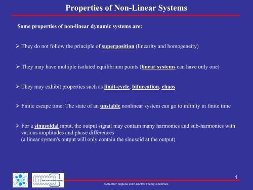
<strong>Properties</strong> <strong>of</strong> <strong>Non</strong>-<strong>Linear</strong> <strong>Systems</strong><br />
Some properties <strong>of</strong> non-linear dynamic systems are:<br />
They do not follow the principle <strong>of</strong> superposition (linearity and homogeneity)<br />
They may have multiple isolated equilibrium points (linear systems can have only one)<br />
They may exhibit properties such as limit-cycle, bifurcation, chaos<br />
Finite escape time: The state <strong>of</strong> an unstable nonlinear system can go to infinity in finite time<br />
For a sinusoidal input, the output signal may contain many harmonics and sub-harmonics with<br />
various amplitudes and phase differences<br />
(a linear system's output will only contain the sinusoid at the output)<br />
CAS-DSP, Sigtuna 2007-Control Theory-S.Simrock<br />
1
Analysis and Control <strong>of</strong> <strong>Non</strong> -<strong>Linear</strong> <strong>Systems</strong><br />
There are several well-developed techniques for analyzing nonlinear feedback systems:<br />
Describing function method<br />
Phase Plane method<br />
Lyapunov stability analysis<br />
Singular Perturbation method<br />
Popov criterion (described in The Lur'e Problem below)<br />
Center manifold theorem<br />
Small-gain theorem<br />
Passivity analysis<br />
CAS-DSP, Sigtuna 2007-Control Theory-S.Simrock<br />
2
Control Design <strong>of</strong> <strong>Non</strong>-<strong>Linear</strong> <strong>Systems</strong><br />
Control design techniques for non-linear systems also exist. These can be subdivided into<br />
techniques which attempt to treat the system as a linear system in a limited range <strong>of</strong> operation and<br />
use (well-known) linear design techniques for each region:<br />
Gain Scheduling<br />
Adaptive control<br />
Those that attempt to introduce auxiliary nonlinear feedback in such a way that the system can<br />
be treated as linear for purposes <strong>of</strong> control design:<br />
Feedback linearization<br />
Lyapunov based methods<br />
Lyapunov Redesign<br />
Back-stepping<br />
Sliding mode control<br />
CAS-DSP, Sigtuna 2007-Control Theory-S.Simrock<br />
3
Describing Function Method<br />
Procedure for analyzing <strong>Non</strong>-<strong>Linear</strong> Control problems based on quasi-linearization<br />
Replacement <strong>of</strong> the non-linear system by a system that is linear except for a dependence on the<br />
amplitude <strong>of</strong> the input waveform<br />
An example might be the family <strong>of</strong> sine-wave inputs; in this case the system would be characterized<br />
by an SIDF or sine input describing function H (A, ω) giving the system response to an input<br />
consisting <strong>of</strong> a sine wave <strong>of</strong> amplitude A and frequency ω.<br />
(This SIDF is a generalization <strong>of</strong> the transfer function H (ω) used to characterize linear systems)<br />
Other types <strong>of</strong> describing functions that have been used are DF's for level inputs and for Gaussian<br />
Noise inputs. The DF's <strong>of</strong>ten suffice to answer specific questions about control and stability.<br />
Example piecewise linear function:<br />
Slope<br />
F<br />
s1<br />
( y)<br />
Slope s2<br />
CAS-DSP, Sigtuna 2007-Control Theory-S.Simrock<br />
Slope<br />
s3<br />
y<br />
4
Phase Plane Method<br />
Refers to graphically determining the existence <strong>of</strong> limit cycles<br />
The Phase Plane, applicable for second order systems only, is a plot with axes being the values <strong>of</strong><br />
the two state variables, vs x x<br />
2<br />
1<br />
[ ( ) ( ) ]<br />
Vectors representing the derivatives f2<br />
x1,x2<br />
, f1<br />
x1,x2<br />
at representative points are drawn<br />
( With enough <strong>of</strong> these arrows in place the system behaviour over the entire plane can be<br />
visualized and limit cycles can be easily identified )<br />
-0.5<br />
x2<br />
-0.5<br />
0.5<br />
0.5<br />
stable<br />
CAS-DSP, Sigtuna 2007-Control Theory-S.Simrock<br />
unstable<br />
x1<br />
5
Lyapunov Stability<br />
Lyapunov stability occurs in the study <strong>of</strong> dynamical systems<br />
In simple terms, if all solutions <strong>of</strong> the dynamical system that start out near an equilibrium point<br />
stay near forever, then is Lyapunov stable<br />
xe e x e x<br />
x e x e x<br />
More strongly, if all solutions that start out near e converge to , then is<br />
asymptotically stable<br />
The notion <strong>of</strong> exponential stability guarantees a minimal rate <strong>of</strong> decay, i.e., an estimate <strong>of</strong> how<br />
quickly the solutions converge<br />
The idea <strong>of</strong> Lyapunov stability can be extended to infinite-dimensional<br />
manifolds, where it is known as Structural Stability, which concerns the behaviour <strong>of</strong> different<br />
but "nearby" solutions to differential equations<br />
CAS-DSP, Sigtuna 2007-Control Theory-S.Simrock<br />
x<br />
2<br />
x1<br />
6
The Lur'e problem<br />
Control systems have a forward path that is linear and time-invariant, and a feedback path that<br />
contains a memory-less, possibly time-varying, static non-linearity<br />
<strong>Linear</strong> Part H(s)<br />
<strong>Non</strong>-<strong>Linear</strong><br />
Part<br />
The linear part can be characterized by four matrices , while the non-linear part is<br />
with a sector non-linearity<br />
By A.I. Lur'e<br />
u y<br />
e<br />
CAS-DSP, Sigtuna 2007-Control Theory-S.Simrock<br />
_<br />
( )<br />
+<br />
A,B,C,D φ(<br />
y)<br />
7
Absolute stability<br />
The marked region in figure is called sector<br />
or shorter<br />
Popov Stability Criteria<br />
u<br />
( e)<br />
0 ≤ F ≤ ke for e > 0<br />
ke ≤ F()<br />
e ≤ 0 for e < 0<br />
( e)<br />
u =<br />
ke<br />
F<br />
0 ≤ ≤ k<br />
e<br />
[ ]<br />
( )<br />
The standard control loop is absolute stable in sector 0,k<br />
, if the closed loop has<br />
only one global asymptotic stable equilibrium for any F e lying in this sector<br />
CAS-DSP, Sigtuna 2007-Control Theory-S.Simrock<br />
e<br />
9
Example for Popov Criteria<br />
The non-linearity is shown as a three-point characteristic, which already hosts<br />
the amplification K <strong>of</strong> the linear subsystem<br />
KLb e<br />
u<br />
1<br />
-a a<br />
- -KLb ( 1+<br />
jω)<br />
( 1+<br />
j2ω)<br />
( 1+<br />
j3ω)<br />
-0.3<br />
Popov frequency response locus Z=L(jω)<br />
ω Im<br />
1<br />
−<br />
K p<br />
0.1<br />
CAS-DSP, Sigtuna 2007-Control Theory-S.Simrock<br />
L(<br />
jω)<br />
-0.2 -0.1 0.1<br />
-0.1<br />
0.2 0.3 0.4 0.5 0.6 0.7 0.8 0.9 1<br />
-0.2<br />
g<br />
Z = L<br />
( jω)<br />
The line g krit is tangential to the Popov frequency response locus curve and<br />
intersects the real axis at 0.1<br />
krit<br />
Re<br />
x<br />
12
The Popov sector is defined by the line<br />
Example for Popov Criteria<br />
u<br />
α<br />
1 a<br />
To verify Popov criteria the gradient <strong>of</strong> three-point characteristic must be smaller the<br />
calculated gradient<br />
K Lb<br />
tanα<br />
=<br />
a<br />
K Lb<br />
a<br />
e<br />
K p<br />
K Lb<br />
a<br />
If this is true for the given inequality, then is idle state global asymptotic stable<br />
< 1<br />
CAS-DSP, Sigtuna 2007-Control Theory-S.Simrock<br />
e<br />
b<br />
K L<br />
e<br />
13
Gain Scheduling<br />
It is an approach to control <strong>of</strong> non-linear systems that uses a family <strong>of</strong> linear controllers, each<br />
<strong>of</strong> which provides satisfactory control for a different operating point <strong>of</strong> the system<br />
One or more observable variables, called the scheduling variables, are used to determine what<br />
operating region the system is currently in and to enable the appropriate linear controller<br />
Aircraft example:<br />
flight control system, the altitude and Mach number might be the scheduling variables, with<br />
different linear controller parameters available for various combinations <strong>of</strong> these two variables.<br />
Pg<br />
Gain change P g<br />
CAS-DSP, Sigtuna 2007-Control Theory-S.Simrock<br />
t<br />
14
Adaptive Control<br />
Modifying the controller parameters to compensate slow time–varying behaviour or uncertainties<br />
For example, as an aircraft flies, its mass will slowly decrease as a result <strong>of</strong> fuel consumption; we<br />
need a control law that adapts itself to such changing conditions<br />
Adaptive control does not need a priori information about the bounds on these uncertain or timevarying<br />
parameters<br />
Robust control guarantees that if the changes are within given bounds the control law need not be<br />
changed<br />
While adaptive control is precisely concerned with control law changes<br />
CAS-DSP, Sigtuna 2007-Control Theory-S.Simrock<br />
15
Feedback <strong>Linear</strong>ization<br />
Common approach used in controlling nonlinear systems<br />
Transformation <strong>of</strong> the nonlinear system into an equivalent linear system through substitution <strong>of</strong><br />
variables and a suitable control input.<br />
Feedback linearization may be applied to nonlinear systems <strong>of</strong> the following form:<br />
x&<br />
=<br />
f<br />
y = h<br />
( x)<br />
+ g(<br />
x)<br />
u ( 1)<br />
( x)<br />
( 2)<br />
The goal is to develop a control input u that renders either the input-output map linear,<br />
or results in a linearization <strong>of</strong> the full state <strong>of</strong> the system<br />
Existence <strong>of</strong> a state Fb control ?<br />
Variable substitution ?<br />
u = α +<br />
z = T<br />
( x)<br />
β(<br />
x)<br />
y<br />
( x)<br />
x<br />
u<br />
y<br />
CAS-DSP, Sigtuna 2007-Control Theory-S.Simrock<br />
state vector<br />
input vector<br />
output vector<br />
17
Task: Stabilization <strong>of</strong> pendulum at the origin<br />
x&<br />
1<br />
x&<br />
2<br />
= x<br />
2<br />
= a<br />
[ sin ( x + δ)<br />
−sin<br />
( δ)<br />
] −bx<br />
+ cu<br />
1. Choose u as follows to cancel nonlinear term:<br />
2. Stabilizing fb controller<br />
1<br />
a<br />
u =<br />
1 +<br />
c<br />
[ sin ( x + δ)<br />
− sin ( δ)<br />
]<br />
c<br />
3. Re-substituting to or fb control law<br />
⎛a⎞<br />
1<br />
u = ⎜ ⎟ 1<br />
1 1 +<br />
⎝c<br />
⎠<br />
c<br />
Pendulum Example<br />
[ sin ( x + δ)<br />
−sin<br />
( δ)<br />
] − ( k x k x )<br />
2<br />
v<br />
Closed loop<br />
2<br />
2<br />
CAS-DSP, Sigtuna 2007-Control Theory-S.Simrock<br />
<strong>Linear</strong> system<br />
x&<br />
1<br />
x&<br />
2<br />
= x<br />
2<br />
= −b⋅<br />
x<br />
1 2<br />
= −k1x1<br />
k2x<br />
2<br />
x&<br />
2 = k1x1<br />
− ( k2<br />
+ b)<br />
x2<br />
v −<br />
x&<br />
=<br />
x<br />
2<br />
+ v<br />
18
Sliding Mode Control<br />
In Control theory Sliding Mode Control is a type <strong>of</strong> variable control structure where the<br />
dynamics <strong>of</strong> a nonlinear system is altered via application <strong>of</strong> a high-frequency switching control<br />
Time varying state feedback control scheme<br />
This control scheme involves following two steps:<br />
Selection <strong>of</strong> a hypersurface or a manifold such that the system trajectory exhibits desirable<br />
behaviour when confined to this manifold<br />
Finding feed-back gains so that the system trajectory intersects and stays on the manifold<br />
Advantages:<br />
Controllers with switching elements are easy to realize<br />
The controller outputs can be restricted to a certain region <strong>of</strong> operation<br />
Can also be used inside the region <strong>of</strong> operation to enhance the closed loop dynamics<br />
CAS-DSP, Sigtuna 2007-Control Theory-S.Simrock<br />
19
Two types <strong>of</strong> switching controllers<br />
Switching between constant values<br />
Sliding Mode Control<br />
Switching between state or output dependent values<br />
Design <strong>of</strong> a switching controller therefore needs<br />
The definition <strong>of</strong> a switching condition<br />
The choice <strong>of</strong> the control law inside the areas separated by the switching law<br />
CAS-DSP, Sigtuna 2007-Control Theory-S.Simrock<br />
20
Consider a linear system<br />
The control law<br />
Sliding Mode Control (Cnt’d)<br />
&y<br />
&=<br />
u<br />
u = −ky<br />
It is clear that controller is not able to stabilize the semi stable system that has two open loop<br />
eigen values <strong>of</strong> zero. The root locus plot with two branches along the imaginary axis<br />
Switching function: ( y, y)<br />
= my y<br />
⎧−<br />
1 s<br />
u = ⎨<br />
⎩ 1 s<br />
with<br />
s & + &<br />
( y, y&<br />
)<br />
( y, y&<br />
)<br />
k > 0<br />
With a scalar m><br />
0,<br />
then a variabale structure control law<br />
> 0<br />
< 0<br />
CAS-DSP, Sigtuna 2007-Control Theory-S.Simrock<br />
21
Consider a second order system<br />
Goal: state FB<br />
stabilize the origin.<br />
Phase Portrait with Example<br />
x&<br />
x&<br />
1<br />
2<br />
=<br />
=<br />
x<br />
h<br />
g( x)<br />
and h(<br />
x)<br />
On the manifold s<br />
the motion is<br />
independent <strong>of</strong> and<br />
g ( x)<br />
h(<br />
x)<br />
2<br />
( x)<br />
+ g(<br />
x)<br />
u<br />
are unknown non-linear functions<br />
= a x + x = 0 x& 1 = −ax1<br />
s 1 1 2<br />
s = 0<br />
x2<br />
CAS-DSP, Sigtuna 2007-Control Theory-S.Simrock<br />
x1<br />
22
Caused by delays<br />
(no ideal sliding on manifold)<br />
s < 0<br />
Region trajectory reverses<br />
Delay leads to crossing again<br />
Disadvantages:<br />
Low control accuracy<br />
Power losses<br />
Excitation <strong>of</strong> unmodeled dynamics<br />
Can result in instabilities<br />
Chattering on Sliding Manifold<br />
s<br />
s < 0<br />
CAS-DSP, Sigtuna 2007-Control Theory-S.Simrock<br />
s > 0<br />
23
What is System Identification?<br />
Using experimental data obtained from input/output relations to model dynamic systems<br />
input<br />
System<br />
disturbances<br />
output<br />
Different approaches to system identification depending on model class<br />
<strong>Linear</strong>/<strong>Non</strong>-linear<br />
Parametric/<strong>Non</strong>-parametric<br />
<strong>Non</strong>-parametric methods try to estimate a generic model<br />
(step responses, impulse responses, frequency responses)<br />
Parametric methods estimate parameters in a user-specified model<br />
(transfer functions, state-space matrices)<br />
CAS-DSP, Sigtuna 2007-Control Theory-S.Simrock<br />
1
Identification Steps<br />
Experiment design :<br />
Its purpose is to obtain good experimental data, and it<br />
includes the choice <strong>of</strong> the measured variables and <strong>of</strong><br />
the character <strong>of</strong> the input signals<br />
Selection <strong>of</strong> model structure :<br />
A suitable model structure is chosen using prior<br />
knowledge and trial and error<br />
Choice <strong>of</strong> the criterion to fit :<br />
A suitable cost function is chosen, which reflects how<br />
well the model fits the experimental data<br />
Parameter estimation :<br />
An optimization problem is solved to obtain the<br />
numerical values <strong>of</strong> the model parameters<br />
Model validation :<br />
The model is tested in order to reveal any inadequacies<br />
No<br />
CAS-DSP, Sigtuna 2007-Control Theory-S.Simrock<br />
Experimental design<br />
Data collection<br />
Data pre-filtering<br />
Model structure selection<br />
Parameter estimation<br />
Model validation<br />
Model ok?<br />
Yes<br />
2
Model description:<br />
Transfer functions<br />
State-space models<br />
Block diagrams (e.g. Simulink)<br />
Notation for continuous time models<br />
Different Mathematical Models<br />
Complex Laplace variable ‘s’ and differential operator ‘p’<br />
Notation for discrete time models<br />
( t)<br />
∂x<br />
x &()<br />
t = =<br />
∂t<br />
p x()<br />
t<br />
Complex z-transform variable and shift operator ‘q’<br />
( k +<br />
1)<br />
q x(<br />
k)<br />
x =<br />
CAS-DSP, Sigtuna 2007-Control Theory-S.Simrock<br />
3
Experiments and Data Collection<br />
Often good to use a two-stage approach<br />
Preliminary experiments<br />
Step/impulse response tests to get basic understanding <strong>of</strong> system dynamics<br />
<strong>Linear</strong>ity, static gains, time delays constants, sampling interval<br />
Data collection for model estimation<br />
Carefully designed experiment to enable good model fit<br />
Operating point, input signal type, number <strong>of</strong> data points to collect<br />
CAS-DSP, Sigtuna 2007-Control Theory-S.Simrock<br />
4
Preliminary Experiments- Step Response<br />
Useful for obtaining qualitative information about the system<br />
Dead time (delay)<br />
Static gain<br />
Time constants (rise time)<br />
Resonance frequency<br />
Sample time can be determined from time constants<br />
Rule-<strong>of</strong>-thumb: 4-10 sample points over the rise time<br />
CAS-DSP, Sigtuna 2007-Control Theory-S.Simrock<br />
5
Design Experiment for Model Estimation<br />
Input signal should excite all relevant frequencies<br />
Estimated model more accurate in frequency ranges where input has high energy<br />
Pseudo-Random Binary Sequence (PRBS) is usually a good choice<br />
Trade-<strong>of</strong>f in selection <strong>of</strong> signal amplitude<br />
Large amplitude gives high signal-to-noise ratio (SNR), low parameter variance<br />
Most systems are non-linear for large input amplitudes<br />
Big difference between estimation <strong>of</strong> system under closed loop control or not!<br />
CAS-DSP, Sigtuna 2007-Control Theory-S.Simrock<br />
6
u(<br />
t)<br />
Lu<br />
u(<br />
k)<br />
Collecting Data<br />
w(<br />
t)<br />
System<br />
y(<br />
t)<br />
Sampling time selection and anti-alias filtering are central!<br />
+<br />
LY<br />
y(<br />
k)<br />
CAS-DSP, Sigtuna 2007-Control Theory-S.Simrock<br />
e(<br />
t)<br />
7
Remove:<br />
Data Pre-Filtering<br />
Transients needed to reach desired operating point<br />
Mean values <strong>of</strong> input and output values, i.e. work with<br />
Δu<br />
Δy<br />
1<br />
N<br />
N<br />
∑<br />
t=<br />
1<br />
[] t = u[]<br />
t − u[]<br />
t<br />
1<br />
N<br />
N<br />
∑<br />
t=<br />
1<br />
[] t = y[]<br />
t − y[]<br />
t<br />
Trends (use ‘detrend’ in MATLAB)<br />
Outliers (obvious erroneous data points)<br />
CAS-DSP, Sigtuna 2007-Control Theory-S.Simrock<br />
8
y<br />
General Model Structure<br />
<strong>Systems</strong> described in terms <strong>of</strong> differential equations and transfer functions<br />
Provides insight into the system physics and a compact model structure<br />
General-linear polynomial model or the general-linear model<br />
u( k)<br />
and y(<br />
k)<br />
−k<br />
−1<br />
−1<br />
( k)<br />
= q G(<br />
q ) u(<br />
k)<br />
+ H ( q ) e(<br />
k)<br />
are the input and output <strong>of</strong> the system<br />
e<br />
( k)<br />
is zero-mean white noise, or the disturbance <strong>of</strong> the system<br />
( )<br />
( )<br />
−1<br />
G q is the transfer function <strong>of</strong> the deterministic part <strong>of</strong> the system<br />
<br />
−1<br />
H<br />
q is the transfer function <strong>of</strong> the stochastic part <strong>of</strong> the system<br />
e(<br />
k)<br />
General-linear model structure:<br />
C<br />
D<br />
B(<br />
q)<br />
1<br />
u ( k)<br />
F(<br />
q)<br />
+<br />
y(<br />
k)<br />
A(<br />
q)<br />
CAS-DSP, Sigtuna 2007-Control Theory-S.Simrock<br />
( q)<br />
( q)<br />
9
Model structures based on input-output:<br />
ARX<br />
ARMAX<br />
Box-Jenkins<br />
Output Error<br />
FIR<br />
Model Structures<br />
Model p~ ( q)<br />
B(q) C<br />
A(q) y [] k = u[]<br />
k +<br />
F(q) D<br />
( q)<br />
( q)<br />
B<br />
A<br />
B<br />
F<br />
B<br />
F<br />
( q)<br />
( q)<br />
( q)<br />
( q)<br />
( q)<br />
( q)<br />
( q)<br />
( q)<br />
B<br />
A<br />
B(<br />
q)<br />
y[]<br />
k<br />
or<br />
CAS-DSP, Sigtuna 2007-Control Theory-S.Simrock<br />
p~<br />
e(<br />
q)<br />
Provides flexibility for system and stochastic dynamics. Simpler models that are a subset<br />
<strong>of</strong> the General <strong>Linear</strong> model structure<br />
1<br />
A(<br />
q)<br />
C(<br />
q)<br />
A(<br />
q)<br />
C(<br />
q)<br />
D(<br />
q)<br />
1<br />
1<br />
[] k = p~ ( q)<br />
u[<br />
k]<br />
+ p~ ( q)<br />
e[<br />
k]<br />
y e<br />
10
Parametric Models<br />
Each <strong>of</strong> these methods has their own advantages and<br />
disadvantages and is commonly used in real-world<br />
applications<br />
Choice <strong>of</strong> the model structure to use depends on the<br />
dynamics and the noise characteristics <strong>of</strong> the system<br />
Using a model with more freedom or parameters<br />
is not always better as it can result in the modeling<br />
<strong>of</strong> nonexistent dynamics and noise characteristics<br />
This is where physical insight into a system is helpful<br />
CAS-DSP, Sigtuna 2007-Control Theory-S.Simrock<br />
AR Model<br />
ARX Model<br />
ARMAX Model<br />
Box-Jenkins Model<br />
Output-Error Model<br />
State-Space Model<br />
11
AR Model<br />
Process model where outputs are only dependent on previous outputs<br />
No system inputs or disturbances are used in the modelling<br />
Class <strong>of</strong> solvable problems is limited, for signals not for systems<br />
Time series analyses, such as linear prediction coding commonly use the AR model<br />
1<br />
y [ k]<br />
=<br />
A<br />
( ) [] k e<br />
q<br />
e(<br />
k)<br />
1<br />
A<br />
( q)<br />
AR Model Structure<br />
CAS-DSP, Sigtuna 2007-Control Theory-S.Simrock<br />
y(<br />
k)<br />
12
Advantages:<br />
ARX Model<br />
Is the most efficient <strong>of</strong> the polynomial estimation methods<br />
solving linear regression equations in analytic form.<br />
Unique solution, that satisfies the global minimum <strong>of</strong> the loss function<br />
Preferable, especially when the model order is high<br />
Disadvantages:<br />
Disturbances are part <strong>of</strong> the system dynamics.<br />
The transfer function <strong>of</strong> the deterministic part G q <strong>of</strong> the system and the transfer function<br />
<strong>of</strong> the stochastic part <strong>of</strong> the system have the same set <strong>of</strong> poles<br />
1 −<br />
H q<br />
1 −<br />
( )<br />
This coupling can be unrealistic<br />
The system dynamics and stochastic dynamics <strong>of</strong> the system do not share the same set <strong>of</strong> poles<br />
all the time<br />
(Can bias the estimation <strong>of</strong> the ARX model)<br />
( )<br />
However, you can reduce this disadvantage if you have a good signal-to-noise ratio<br />
CAS-DSP, Sigtuna 2007-Control Theory-S.Simrock<br />
13
ARX Model (Cnt‘d)<br />
Set the model order higher than the actual model order to minimize the equation error,<br />
especially when the signal-to-noise ratio is low<br />
However, increasing the model order can change some dynamic characteristics <strong>of</strong> the<br />
model, such as the stability <strong>of</strong> the model<br />
( q)<br />
( q)<br />
B<br />
y [ k]<br />
=<br />
u[<br />
k]<br />
+<br />
A<br />
1<br />
A<br />
( ) [] k e<br />
q<br />
u ( k)<br />
B(<br />
q)<br />
e(<br />
k)<br />
+<br />
ARX Model Structure<br />
CAS-DSP, Sigtuna 2007-Control Theory-S.Simrock<br />
1<br />
A(<br />
q)<br />
y(<br />
k)<br />
14
Includes disturbance dynamics!<br />
ARMAX Model<br />
ARMAX models are useful when you have dominating disturbances that enter early in the<br />
process, such as at the input<br />
i.e. a wind gust affecting an aircraft is a dominating disturbance early in the process<br />
More flexibility in the handling <strong>of</strong> disturbance modelling<br />
( q)<br />
( q)<br />
B C<br />
y [ k]<br />
=<br />
u[<br />
k]<br />
+<br />
A A<br />
( q)<br />
( q)<br />
e<br />
[ ] k<br />
e(<br />
k)<br />
C(<br />
q)<br />
u ( k)<br />
B(<br />
q)<br />
+<br />
y(<br />
k)<br />
A(<br />
q)<br />
ARMAX Model Structure<br />
CAS-DSP, Sigtuna 2007-Control Theory-S.Simrock<br />
1<br />
15
Box Jenkins Model<br />
Provides a complete model with disturbance properties modelled separately<br />
from system dynamics<br />
The Box-Jenkins model is useful when you have disturbances that enter late in the process<br />
For example, measurement noise on the output is a disturbance late in the process<br />
( not output error model)<br />
B(<br />
q ) C(<br />
q )<br />
y +<br />
F(<br />
q ) D(<br />
q )<br />
[] k =<br />
u[]<br />
k e[]<br />
k<br />
e(<br />
k)<br />
C<br />
D<br />
( q)<br />
( q)<br />
B(<br />
q)<br />
u ( k)<br />
F(<br />
q)<br />
+ y(<br />
k)<br />
Box-Jenkins Model Structure<br />
CAS-DSP, Sigtuna 2007-Control Theory-S.Simrock<br />
16
Describes the system dynamics separately<br />
Output Error Model<br />
No parameters are used for modelling the disturbance characteristics<br />
( q)<br />
( q)<br />
[] u<br />
B<br />
y k =<br />
+<br />
F<br />
[ ] [ ] k e k<br />
e(<br />
k)<br />
B(<br />
q)<br />
u ( k)<br />
F(<br />
q)<br />
+ y(<br />
k)<br />
OE Model Structure<br />
CAS-DSP, Sigtuna 2007-Control Theory-S.Simrock<br />
17
State Space Model<br />
All previous methods are based on minimizing a performance function<br />
For complex high order systems the classical methods can suffer from several problems<br />
Find many local minima in the performance function and don’t converge to global minima<br />
The user will need to specify complicated parameterization. They also may suffer potential<br />
problems with numerical instability and excessive computation time to execute the iterative<br />
numerical minimization methods needed<br />
In addition, modern control methods require a state-space model <strong>of</strong> the system<br />
For cases such as these the State-Space (SS) identification method is the appropriate model<br />
structure<br />
Hint:<br />
When the model order is high, use an ARX model because the algorithm involved in ARX model estimation is fast<br />
and efficient when the number <strong>of</strong> data points is very large. The state-space model estimation with a large number <strong>of</strong><br />
data points is slow and requires a large amount <strong>of</strong> memory. If you must use a state-space model, for example in<br />
modern control methods, reduce the sampling rate <strong>of</strong> the signal in case the sampling rate is unnecessarily high.<br />
CAS-DSP, Sigtuna 2007-Control Theory-S.Simrock<br />
18
x<br />
y<br />
State Space (Cnt‘d)<br />
( k + 1)<br />
= A x(<br />
k)<br />
+ B u(<br />
k)<br />
+ K e(<br />
k)<br />
( k)<br />
= C x(<br />
k)<br />
+ D u(<br />
k)<br />
+ e(<br />
k)<br />
x(<br />
k)<br />
CAS-DSP, Sigtuna 2007-Control Theory-S.Simrock<br />
state vector<br />
y( k)<br />
system output<br />
u(<br />
k)<br />
e(<br />
k)<br />
system input<br />
stochastic error<br />
A,B,C,D, and K:<br />
system matrices.<br />
In general, they provide a more complete representation <strong>of</strong> the system, especially for complex<br />
MIMO systems<br />
The identification procedure does not involve nonlinear optimization so the estimation reaches<br />
a solution regardless <strong>of</strong> the initial guess<br />
Parameter settings for the state-space model are simpler<br />
You need to select only the order / states, <strong>of</strong> the model<br />
Prior knowledge <strong>of</strong> the system or by analyzing the singular values <strong>of</strong> A<br />
19
Determine Parameters<br />
Determining the delay and model order for the prediction error methods,<br />
ARMAX, BJ, and OE, is typically a trial-and-error process<br />
The following is a useful set <strong>of</strong> steps that can lead to a suitable model<br />
(this is not the only methodology you can use, nor is this a comprehensive procedure)<br />
(1) Obtain useful information about the model order by observing the number <strong>of</strong> resonance peaks<br />
in the nonparametric frequency response function. Normally, the number <strong>of</strong> peaks in the<br />
A q , F q<br />
magnitude response equals half the order <strong>of</strong> ( ) ( )<br />
(2) Obtain a reasonable estimate <strong>of</strong> delay using correlation analysis and/or by testing reasonable<br />
values in a medium size ARX model. Choose the delay that provides the best model fit based<br />
on prediction error or other fit criterion<br />
(3) Test various ARX model orders with this delay choosing those that provide the best fit<br />
(4) Since the ARX model describes both the system dynamics and noise properties using the same<br />
set <strong>of</strong> poles, the resulting model may be unnecessarily high in order<br />
(5) By plotting the zeros and poles and looking for cancellations you can reduce the model order<br />
CAS-DSP, Sigtuna 2007-Control Theory-S.Simrock<br />
20
Determine Parameters (Cnt’d)<br />
(5) Are there additional signals? Measurements can be incorporated as extra input signals!<br />
(6) If you cannot obtain a suitable model following these steps additional physical insight into<br />
the problem might be necessary.<br />
( Compensating for nonlinear sensors or actuators and handling <strong>of</strong> important physical<br />
non - linearities are <strong>of</strong>ten necessary in addition to using a ready-made model )<br />
The higher the order <strong>of</strong> the model is, the better the model fits the data because the model<br />
has more degrees <strong>of</strong> freedom.<br />
(but you need more computation time and memory)<br />
Choosing the model with the smallest degree <strong>of</strong> freedom, or number <strong>of</strong> parameters,<br />
if all the models fit the data well and pass the verification test.<br />
CAS-DSP, Sigtuna 2007-Control Theory-S.Simrock<br />
21
Variety <strong>of</strong> model structures available<br />
Conclusion<br />
Choice is based upon an understanding <strong>of</strong> the system identification method and algorithm<br />
System and disturbance are important<br />
Handling a wide range <strong>of</strong> system dynamics without knowing system physics<br />
Reduction <strong>of</strong> engineering effort<br />
Identification Tools (Matlab, Matrix or LabVIEW ) are available for developing, prototyping<br />
and deploying control algorithms<br />
CAS-DSP, Sigtuna 2007-Control Theory-S.Simrock<br />
22
Matlab System Identification Tool<br />
CAS-DSP, Sigtuna 2007-Control Theory-S.Simrock<br />
23