ASSEMBLY INSTRUCTIONS S O L O N STANDARD MODULES
ASSEMBLY INSTRUCTIONS S O L O N STANDARD MODULES
ASSEMBLY INSTRUCTIONS S O L O N STANDARD MODULES

Create successful ePaper yourself
Turn your PDF publications into a flip-book with our unique Google optimized e-Paper software.
Technical Service<br />
Table 2: Assembly area "M S " – vertical assembly<br />
Standardmodule L<br />
[mm]<br />
B<br />
[mm]<br />
a optimal<br />
[mm]<br />
a min<br />
[mm]<br />
M S<br />
[mm]<br />
SOLON Blue 230/07 1.640 1.000 980 510 565<br />
SOLON Black 230/07 (01, 02) 1.640 1.000 980 510 565<br />
SOLON Blue 220/03 (01, 07) 1.640 1.000 980 510 565<br />
SOLON Black 280/10, 1.580 1.070 940 540 520<br />
SOLON Black 300/10 1.580 1.070 940 540 520<br />
SOLON P220/6+/07 1.640 1.000 980 510 565<br />
SOLON M230/6+/07 1.640 1.000 980 510 565<br />
SOLON M230/6+/01 1.640 1.000 980 510 565<br />
SOLON P220/6+ 1.660 990 1.000 530 565<br />
SOLON M230/6+ 1.660 990 1.000 530 565<br />
SOLON P180/6+ 1.660 830 1.000 530 565<br />
SOLON P130/6+ 1.500 680 900 470 515<br />
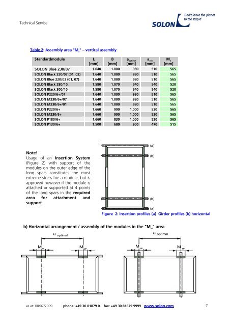
Note!<br />
Usage of an Insertion System<br />
(Figure 2) with support of the<br />
modules on the outer edge of the<br />
long spars constitutes the most<br />
extreme stress foe a module, but is<br />
approved however if the module is<br />
attached or supported at 4 points<br />
of the long spars in the required<br />
area for attachment and<br />
support.<br />
b) Horizontal arrangement / assembly of the modules in the "M w " area<br />
M w<br />
a optimal<br />
M w<br />
(a)<br />
Figure 2: Insertion profiles (a) Girder profiles (b) horizontal<br />
a optimal<br />
as at: 08/07/2009 phone: +49 30 81879 0 fax: +49 30 81879 9999 www.solon.com 7<br />
M w<br />
(a)<br />
(b)<br />
(b)<br />
M w