move or add ceiling lights - Homebase
move or add ceiling lights - Homebase
move or add ceiling lights - Homebase

You also want an ePaper? Increase the reach of your titles
YUMPU automatically turns print PDFs into web optimized ePapers that Google loves.
how to...<br />
<strong>move</strong> <strong>or</strong> <strong>add</strong><br />
<strong>ceiling</strong> <strong>lights</strong><br />
A brief guide. Skill rating: advanced<br />
If you are looking to <strong>move</strong> a <strong>ceiling</strong> light <strong>or</strong> want to <strong>add</strong> <strong>add</strong>itional<br />
light fixtures, this guide offers some step-by-step instructions<br />
and handy hints to help you undertake the w<strong>or</strong>k.<br />
Always use the manufacturer’s instructions when fitting any new electrical<br />
equipment. If you are at all unsure, always get the assistance of a qualified<br />
electrician. <strong>Homebase</strong> recommend the use of NICEIC registered electricians<br />
f<strong>or</strong> electrical installation w<strong>or</strong>k.<br />
be aware<br />
This guide is only suitable if you are moving <strong>or</strong> <strong>add</strong>ing new <strong>ceiling</strong><br />
<strong>lights</strong> if using the existing light switch and wiring. If <strong>add</strong>ing new <strong>ceiling</strong><br />
<strong>lights</strong>, it also assumes you have access to the <strong>ceiling</strong> void from above.<br />
In the UK, ALL w<strong>or</strong>k should be carried out to BS7671 and Approved<br />
Document P of the Building Regulations and it is illegal to w<strong>or</strong>k on<br />
electrical installations in a kitchen, bathroom <strong>or</strong> garden without it<br />
being inspected and approved by a Part P registered electrician <strong>or</strong><br />
pri<strong>or</strong> notification to a local Building Control Officer. The replacement<br />
of access<strong>or</strong>ies is deemed acceptable if carried out in a competent<br />
manner.<br />
CLASS 1 equipment (metal fittings that rely on earthing as their<br />
protective measure) can only be installed where there is a reliable<br />
earth at the point of installation.<br />
In some older installations (approx pre 1966) lighting circuits may be<br />
found wired without an earthing facility. On no account should Class<br />
1 equipment be connected to such an installation. Contact a qualified<br />
electrician.<br />
Electrical<br />
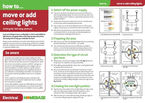
1: Switch off the power supply<br />
If you are in any doubt of ensuring that the circuit to be w<strong>or</strong>ked on is<br />
dead and appropriately isolated, we would recommend you refer to the<br />
Electrical Safety Council’s “Guidance on safe isolation procedures f<strong>or</strong> low<br />
voltage installations”.<br />
Always switch off the power supply at the consumer unit (also known<br />
as the fuse box) bef<strong>or</strong>e starting any electrical w<strong>or</strong>k.<br />
If you are able, turn on the relevant light bef<strong>or</strong>e you turn off the power<br />
supply, to check that you’ve turned off the c<strong>or</strong>rect circuit breaker <strong>or</strong> fuse.<br />
Either take out the relevant fuse <strong>or</strong> ensure that the relevant miniature<br />
circuit breaker (MCB) is in the off position and effectively disabled and<br />
cannot theref<strong>or</strong>e be accidentally switched back on.<br />
2: Preparing the area<br />
Make sure you can reach the <strong>ceiling</strong> light fittings without over extending<br />
yourself by standing on a safe structure – e.g. a l<strong>add</strong>er.<br />
Then with the power disconnected and verified dead as detailed in<br />
Section 1, re<strong>move</strong> the bulb, lampshade and existing <strong>ceiling</strong> rose cover<br />
(n<strong>or</strong>mally you can unscrew) to reveal rose mounting box and wiring.<br />
3: Determine the type of circuit<br />
you have<br />
Wiring colours in the UK were changed in April 2006, (fig. 1) shows the<br />
wiring colours f<strong>or</strong> installations pre and post April 2006.<br />
Where differing wiring identification colours exist, a warning label should<br />
be attached at the consumer unit.<br />
Now you can determine if you are w<strong>or</strong>king with a junction box <strong>or</strong> loop-in<br />
circuit. Junction box circuits usually have only one cable entering the rose<br />
mounting box, however it is possible f<strong>or</strong> junction box circuits to have two<br />
<strong>or</strong> m<strong>or</strong>e cables, where a <strong>ceiling</strong> rose in a junction box circuit has been used<br />
to loop one <strong>or</strong> m<strong>or</strong>e light fittings into it; loop-in circuits have two <strong>or</strong> three.<br />
The process f<strong>or</strong> moving <strong>or</strong> <strong>add</strong>ing <strong>ceiling</strong> <strong>lights</strong> varies by the type of circuit<br />
(fig. 2a & 2b).<br />
4: Creating the new light position<br />
Determine the c<strong>or</strong>rect position of the new light fitting and make a small<br />
hole in the <strong>ceiling</strong> using a bradawl, old small screwdriver <strong>or</strong> nail to<br />
minimise the chance of damaging a hidden cable <strong>or</strong> pipe etc.<br />
Make sure there are no wires within the <strong>ceiling</strong> void that you might cut<br />
<strong>or</strong> touch when drilling through the <strong>ceiling</strong> into the void.<br />
how to... <strong>move</strong> <strong>or</strong> <strong>add</strong> <strong>ceiling</strong> <strong>lights</strong><br />
<br />
New colours (Post April 2006)<br />
Power<br />
cable<br />
circuit<br />
Power<br />
cable<br />
circuit<br />
Switch cable<br />
Two c<strong>or</strong>e and earth<br />
Three c<strong>or</strong>e and earth<br />
Old colours (Pre April 2006)<br />
(fig. 1) Wiring colours pre and post April 2006<br />
(fig. 2b) Junction box wiring<br />
Mark with<br />
brown tape<br />
Two c<strong>or</strong>e and earth<br />
Three c<strong>or</strong>e and earth<br />
Light flex<br />
Ceiling rose<br />
Junction box<br />
Switch<br />
cable<br />
Switch<br />
Light spur cable –<br />
to <strong>ceiling</strong> rose<br />
New spur<br />
Power<br />
cable<br />
circuit<br />
(fig. 4) Typical junction box wiring with new<br />
spur<br />
(fig. 2a) Loop in wiring<br />
<br />
<br />
Power<br />
cable<br />
circuit<br />
Replace old spur<br />
with new spur<br />
Power<br />
cable<br />
circuit<br />
Switch cable<br />
Light spur cable –<br />
to <strong>ceiling</strong> rose<br />
(fig. 3) Typical four terminal junction<br />
box wiring<br />
Power<br />
cable<br />
circuit<br />
Switch<br />
cable<br />
Earth<br />
terminal<br />
Light flex<br />
Light flex<br />
Ceiling rose<br />
Switch<br />
cable<br />
Switch<br />
Power<br />
cable<br />
circuit<br />
Mark with<br />
brown tape<br />
Light spur cable<br />
to new <strong>ceiling</strong><br />
rose<br />
Power<br />
cable<br />
circuit<br />
Switch<br />
cable, mark<br />
with brown<br />
tape<br />
(fig. 5) Loop-in wiring rose mounting box with<br />
new spur
how to... <strong>move</strong> <strong>or</strong> <strong>add</strong> <strong>ceiling</strong> <strong>lights</strong><br />
Tools f<strong>or</strong> the job...<br />
Screwdriver Small Insulated screwdriver<br />
Electric drill Four terminal junction box<br />
1mm2 two-c<strong>or</strong>e-and-earth cable<br />
Light fi tting – pendant set<br />
Bradawl<br />
L<strong>add</strong>er<br />
Nails<br />
Different coloured tape<br />
www.recyclenow.com<br />
Please recycle this fl yer<br />
HBHOWDO44 October 2010<br />
5: Re<strong>move</strong> the existing light fl ex<br />
<br />
Disconnect all of the wires connecting the existing light fitting to the rose<br />
mounting box by releasing from the terminals with a small screwdriver.<br />
Bef<strong>or</strong>e you disconnect any wires, make a note of which terminal each wire<br />
connects to, so you can refl ect this sequence when you make any changes.<br />
Marking each wire with different coloured tapes and using a digital camera <strong>or</strong><br />
mobile phone camera could help you.<br />
6: Relocating a light (junction box wiring)<br />
a. Using a screwdriver, carefully release the junction box light spur cable wiring<br />
from terminals on the rose mounting box and then unscrew the rose mounting<br />
box from the <strong>ceiling</strong>.<br />
b. Take the junction box light cable and push it back up into the <strong>ceiling</strong> void.<br />
c. The next steps now take place within the <strong>ceiling</strong> void.<br />
d. If the existing light spur cable is long enough to reach the new position, you<br />
could use it to connect the new light fitting to (assuming in good repair). Take<br />
the existing cabling and feed it through the new hole. Now fix your new <strong>ceiling</strong><br />
rose to the new location.<br />
e. If it’s not long enough, you will have to replace with a new length of 1mm2 <strong>or</strong><br />
1.5mm2 two-c<strong>or</strong>e-and-earth cable, extending from the existing junction box<br />
to the new light position, running the new cable to avoid it being in contact<br />
with thermal insulation <strong>or</strong> a source of heat – e.g. central heating pipe w<strong>or</strong>k. If<br />
required, follow steps f to m.<br />
f. Trace the existing light spur cable back to the junction box (fi g. 3).<br />
g. Take the junction box cover off and using a screwdriver disconnect the existing<br />
light spur cable wires from the terminals in the junction box being careful not to<br />
displace any of the other wires. Take a note of the existing terminal connection<br />
points so you can replicate the sequence.<br />
h. Connect the new two-c<strong>or</strong>e-and-earth cable to the c<strong>or</strong>rect terminals on the<br />
junction box, making sure you sleeve the bare earth wire with a green and<br />
yellow sleeve. Then put the junction box cover back on.<br />
i. Feed the new lighting cable through your new hole and enter the room again.<br />
j. Hold the rose mounting box in place and mark the screw positions f<strong>or</strong> attaching<br />
to the <strong>ceiling</strong>.<br />
k. Connect the new lighting cable to the rose mounting box. You can now fix the<br />
rose mounting box to the new <strong>ceiling</strong> position with the screws provided.<br />
l. Screw on the <strong>ceiling</strong> rose cover, <strong>add</strong> a lampshade (if applicable) and bulb, then<br />
switch on the power supply.<br />
m. Hide the marks left where the old light once was with filler and paint.<br />
7: Adding a new light (junction box wiring)<br />
<br />
F<strong>or</strong> junction box circuits you can either <strong>add</strong> a new junction box into the power<br />
cable circuit <strong>or</strong> <strong>add</strong> a spur from an existing junction box (we only focus on this<br />
option). Alternatively, <strong>add</strong> a spur from an existing <strong>ceiling</strong> rose to your new light<br />
location, as per section 9.<br />
<br />
<br />
m<strong>or</strong>e how to leafl ets available at homebase.co.uk<br />
Having created a new light position (section 4), now follow the same procedure<br />
in section 6, but instead of replacing the old light spur cable, attach the new light<br />
spur wires to the terminals into an existing junction box.<br />
Connect the live (brown <strong>or</strong> red) wire to the existing live (brown <strong>or</strong> red wire)<br />
terminal; its neutral (blue <strong>or</strong> black) wire to power circuit neutral (blue <strong>or</strong> black)<br />
terminal and its earth wire (sleeved in green and yellow) to the earth terminal<br />
(fi g. 4).<br />
8: Relocating a light (loop-in wiring)<br />
a. Using a screwdriver, release the wires from the terminals on the rose mounting<br />
box f<strong>or</strong> each attached cable, then unscrew the box.<br />
b. Push all the loose cables back up into the <strong>ceiling</strong> void.<br />
c. The next steps now take place within the <strong>ceiling</strong> void.<br />
d. Take a new four-terminal junction box and connect the wires of the loose cables<br />
you have just pushed through into the <strong>ceiling</strong> void (fi g. 3).<br />
e. Connect the live (brown <strong>or</strong> red), neutral (blue <strong>or</strong> black) and earth (bare) wires<br />
of the power circuit cable(s) to three separate terminals within the junction box,<br />
cover the bare wire with a green and yellow sleeve.<br />
f. Taking the switch cable, connect the live (brown <strong>or</strong> red) wire to the designated<br />
live terminal, the earth (bare) wire to the designated earth terminal (sleeve wire<br />
as above) and the (blue <strong>or</strong> black) wire to the fourth terminal that’s currently<br />
unused. The blue <strong>or</strong> black cable connected to the fourth terminal should be<br />
marked/sleeved with brown tape, to show it’s live.<br />
g. O nce completed run a new length of 1mm2 <strong>or</strong> 1.5mm2 two-c<strong>or</strong>e-and-earth light<br />
spur cable, extending from the location of the new light position and wire it into the<br />
new four-terminal junction box, connect its live (brown <strong>or</strong> red) wire to the fourth<br />
terminal where the neutral (blue <strong>or</strong> black) switch wire has been connected; its<br />
neutral (blue <strong>or</strong> black) wire to the power cable neutral (blue <strong>or</strong> black) terminal and<br />
its earth wire (sleeved in green and yellow) to the earth terminal.<br />
h. To complete the job, follow steps 6i to 6m.<br />
In line with the requirements of BS7671 the junction box, (with its screwed<br />
terminations) must always be accessible f<strong>or</strong> inspection.<br />
9: Adding a new light (loop-in wiring)<br />
<br />
To <strong>add</strong> a new light within a room on the same light switch, you can simply <strong>add</strong> a<br />
spur from an existing <strong>ceiling</strong> rose to your new light location.<br />
Having completed sections 2 to 4, connect a new length of 1mm2 <strong>or</strong> 1.5mm 2<br />
two-c<strong>or</strong>e-and-earth cable, extending from the location of your new light position<br />
to the <strong>ceiling</strong> rose you’ve chosen to <strong>add</strong> the spur to.<br />
<br />
<br />
<br />
Feed the new spur cable from the <strong>ceiling</strong> void into the back of the existing rose<br />
mounting box (fi g. 5). Temp<strong>or</strong>arily take out the screws holding the box to the<br />
<strong>ceiling</strong>, to give room to manoeuvre.<br />
Connect the live (brown <strong>or</strong> red) wire to the fourth terminal where the blue <strong>or</strong><br />
black with brown sleeving switch wire has been connected; its neutral (blue<br />
<strong>or</strong> black) wire to power circuit neutral (blue <strong>or</strong> black) terminal and its earth wire<br />
(sleeved in green and yellow) to the earth terminal.<br />
To complete the job, follow steps 6i to 6m.