Industrial Dovetail Jig - Vermont American
Industrial Dovetail Jig - Vermont American
Industrial Dovetail Jig - Vermont American

Create successful ePaper yourself
Turn your PDF publications into a flip-book with our unique Google optimized e-Paper software.
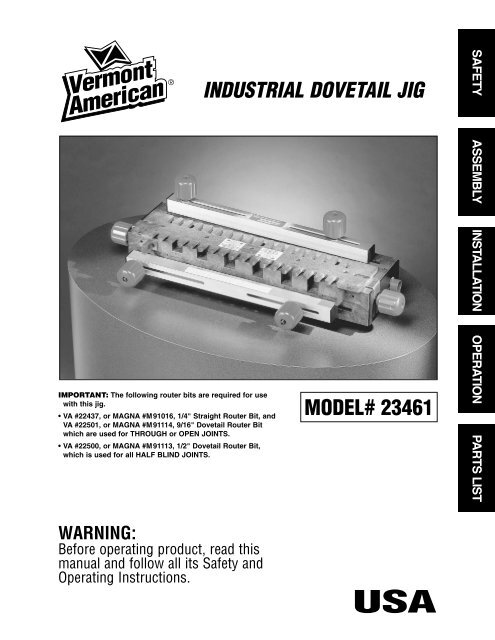
IMPORTANT: The following router bits are required for use<br />
with this jig.<br />
• VA #22437, or MAGNA #M91016, 1/4" Straight Router Bit, and<br />
VA #22501, or MAGNA #M91114, 9/16" <strong>Dovetail</strong> Router Bit<br />
which are used for THROUGH or OPEN JOINTS.<br />
• VA #22500, or MAGNA #M91113, 1/2" <strong>Dovetail</strong> Router Bit,<br />
which is used for all HALF BLIND JOINTS.<br />
WARNING:<br />
Before operating product, read this<br />
manual and follow all its Safety and<br />
Operating Instructions.<br />
®<br />
INDUSTRIAL DOVETAIL JIG<br />
MODEL# 23461<br />
SAFETY ASSEMBLY INSTALLATION OPERATION PARTS LIST<br />
FRANÇAIS/<br />
ESPAÑOL
TABLE OF CONTENTS<br />
General Safety Instructions for Power Tools .......................................... 3<br />
Additional Safety Instructions for <strong>Industrial</strong> <strong>Dovetail</strong> <strong>Jig</strong> ...................... 4<br />
Introduction ................................................................................................ 5<br />
Unpacking and Checking Contents .......................................................... 5<br />
Assembly .................................................................................................... 6<br />
Assembly of the Right Side Template Support to the <strong>Dovetail</strong> Base .............. 6<br />
Assembly of the Top Clamping Bar to the <strong>Dovetail</strong> Base.................................. 7<br />
Assembly of the Front Clamping Bar to the <strong>Dovetail</strong> Base .............................. 9<br />
Assembly of the Cam Handles and Pivot Shaft to the <strong>Dovetail</strong> Base .............. 10<br />
Assembly of the Front Stop Blocks to the <strong>Dovetail</strong> Base ................................ 13<br />
Assembly of the Top Stop Blocks to the <strong>Dovetail</strong> Base .................................... 14<br />
Assembly of the Clamping Knobs to the <strong>Dovetail</strong> Base.................................... 14<br />
Assembly of the Templates .................................................................................. 15<br />
Alignment of the Templates .................................................................................. 16<br />
Assembly of the Adapter Plate to the Router...................................................... 18<br />
Assembly of the Guide Bushing to the Router .................................................. 21<br />
Installation .................................................................................................. 22<br />
Operation .................................................................................................... 24<br />
Styles of <strong>Dovetail</strong> Joints ...................................................................................... 24<br />
Half Blind Flush Joint ...................................................................................... 24<br />
Half Blind Flush Offset Joint............................................................................ 25<br />
Half Blind Rabbeted Joint ................................................................................ 25<br />
Open or Through Joint .................................................................................... 26<br />
Adjusting the Depth-of-Cut of the Router Bit...................................................... 26<br />
Clamping the Workpieces to the <strong>Dovetail</strong> Base ................................................ 28<br />
Making Drawers with Half Blind Flush Joints .................................................... 29<br />
Making Drawers with Half Blind Flush Offset Joints.......................................... 35<br />
Making Drawers with Half Blind Rabbeted Joints .............................................. 35<br />
Making Projects with Open (Through) Joints .................................................... 37<br />
Parts List .................................................................................................... 47<br />
2
This manual contains information<br />
that is important for you to<br />
know and understand. This<br />
information relates to protecting<br />
YOUR SAFETY and<br />
PREVENTING EQUIPMENT<br />
PROBLEMS. To help you recognize<br />
this information, we use<br />
the symbols to the right.<br />
Please read the manual and<br />
pay attention to these sections.<br />
SAFETY GUIDELINES – DEFINITIONS<br />
URGENT SAFETY INFORMATION - A<br />
HAZARD THAT WILL CAUSE SERI-<br />
OUS INJURY OR LOSS OF LIFE<br />
IMPORTANT SAFETY INFORMA-<br />
TION- A HAZARD THAT MIGHT<br />
CAUSE SERIOUS INJURY OR LOSS<br />
OF LIFE<br />
3<br />
INFORMATION FOR PREVENTING<br />
DAMAGE TO EQUIPMENT<br />
INFORMATION THAT YOU SHOULD<br />
PAY SPECIAL ATTENTION TO<br />
GENERAL SAFETY INSTRUCTIONS FOR POWER TOOLS<br />
WARNING<br />
Failure to heed all safety and operating instructions and warnings regarding use of this<br />
product can result in serious bodily injury.<br />
1. Know your power tool<br />
Read the owner’s manual carefully. Learn its<br />
application and limitations as well as the specific potential<br />
hazards peculiar to this tool.<br />
2. Ground all tools (unless double insulated)<br />
If tool is equipped with an approved three-conductor cord<br />
and a three-prong grounding type plug, it should be<br />
plugged into a three hole electrical receptacle. If adapter is<br />
used to accommodate a two-hole receptacle, the adapter<br />
wire must be attached<br />
to a known ground (usually the screw securing<br />
receptacle cover plate). Never remove third prong.<br />
Never connect green ground wire to a terminal.<br />
3. Keep guards in place<br />
Maintain in working order, and in proper adjustment and<br />
alignment.<br />
4. Remove adjusting keys and wrenches<br />
Form a habit of checking to see that keys and adjusting<br />
wrenches are removed from tool before turning it ON.<br />
5. Keep work area clean<br />
Cluttered areas and benches invite accidents.<br />
Floor must not be slippery due to wax or sawdust.<br />
6. Avoid dangerous environment<br />
Do not use power tools in damp or wet locations<br />
or expose them to rain. Keep work area well lighted.<br />
Provide adequate surrounding work space.<br />
7. Keep children away<br />
All visitors should be kept a safe distance from work<br />
area.<br />
WARNING<br />
CAUTION<br />
8. Make workshop child-proof<br />
Use padlocks, master switches, or remove starter keys.<br />
9. Do not force tools<br />
Do not force tool or attachment to do a job it was<br />
not designed to perform.<br />
10. Use the right tool<br />
They will do the job better and safer at the rate<br />
for which they were designed.<br />
11. Wear correct apparel<br />
Do not wear loose clothing, gloves, neckties or<br />
jewelry (rings, wristwatches) that may get caught<br />
in moving parts. Non-slip footwear is recommended. Wear<br />
protective hair covering to contain long hair. Roll long<br />
sleeves above the elbow.<br />
12. Use safety goggles (Head Protection)<br />
Wear safety goggles (must comply with ANSI Standard<br />
Z87.1) at all times. Also, use face or<br />
dust mask, if cutting operation is dusty, and ear<br />
protectors (plugs or muffs) during extended periods of<br />
operation.<br />
13. Secure work<br />
Use clamps or a vise to hold work when practical. It’s safer<br />
than using your hands, and both hands<br />
are free to operate tool.<br />
14. Do not overreach<br />
Keep proper footing and balance at all times.<br />
15. Maintain tools with care<br />
Keep tools sharp and clean for best and safest<br />
performance. Follow instructions for lubricating<br />
and changing accessories.<br />
SAFETY
16. Disconnect tools before servicing<br />
Before servicing, when changing accessories<br />
such as blades, bits, cutters, etc.<br />
17. Avoid accidental starting<br />
Make sure switch is in OFF position before plugging in.<br />
18. Use recommended accessories<br />
Consult the owner’s manual for recommended accessories<br />
and follow the instructions. The use<br />
of improper accessories may cause hazards.<br />
19. Never stand on tool<br />
Serious injury could occur if the tool is tipped or if the cutting<br />
tool is accidentally contacted. DO NOT store materials<br />
above or near the tool making it<br />
necessary to stand on the tool to reach them.<br />
20. Check damaged parts<br />
Before further use of the tool, any guard or other<br />
part that is damaged should be carefully checked to<br />
ensure that it will operate properly and perform its<br />
intended function. Check for alignment of moving<br />
parts, binding of moving parts, breakage of parts,<br />
mounting, and any other conditions that may affect<br />
its operation. A guard or any other part that is<br />
damaged should be properly repaired or replaced.<br />
1. Always wear eye protection that complies with<br />
ANSI Standard Z87.1.<br />
2. Noise levels vary widely. To avoid possible hearing<br />
damage, wear ear plugs or muffs when using the<br />
<strong>Dovetail</strong> <strong>Jig</strong> for hours at a time.<br />
3. For dusty operations, wear a dust mask along<br />
with safety goggles.<br />
4. Do not use this <strong>Dovetail</strong> <strong>Jig</strong> with router bits or<br />
guide bushings other than those specified for the<br />
cuts being made.<br />
5. Follow the instructions in your Router Owner’s<br />
Manual.<br />
6.Vibrations caused by the router during use can<br />
cause fasteners to become loose. Before use and<br />
periodically during use, check all fasteners to make<br />
sure that they are all are tight and secure.<br />
7. Do not use this product until all assembly installation<br />
steps have been completed, and you have read<br />
and understand all safety and operational instructions<br />
in this manual, and the Router Owners Manual.<br />
8. Make sure that the router bit is properly positioned<br />
in the router so that it does not contact the guide<br />
bushing or the template when cutting.<br />
9. The <strong>Dovetail</strong> <strong>Jig</strong> must be securely mounted to a<br />
workbench or other stable surface when in use. The<br />
front of the base should overhang the front of the<br />
4<br />
21. Direction of feed<br />
Feed work into a blade or cutter AGAINST the<br />
direction of rotation of the blade or cutter only.<br />
22. Never leave tool running unattended<br />
Turn power OFF. DO NOT leave tool until it comes<br />
to a complete stop.<br />
23. Keep hands away from cutting area<br />
24. Store idle tools<br />
When not in use, tools should be stored in dry,<br />
high or locked-up place – out of reach of children.<br />
25. Do not abuse cord<br />
Keep cord away from heat, oil and sharp edges.<br />
26. Outdoor extension cords<br />
When tool is used outdoors, use only extension<br />
cords suitable for use outdoors and so marked.<br />
27. Never use in an explosive atmosphere<br />
Normal sparking of the motor could ignite fumes,<br />
flammable liquids, or combustible items.<br />
28. Drugs, alcohol, medication<br />
DO NOT operate tool while under the influence<br />
of drugs, alcohol, or any medication.<br />
Read and Understand this instruction book<br />
completely BEFORE using this product. .<br />
ADDITIONAL SAFETY INSTRUCTIONS FOR THE<br />
INDUSTRIAL DOVETAIL JIG<br />
workbench by no more than 1/4" to provide clearance<br />
when clamping workpieces to the <strong>Dovetail</strong> <strong>Jig</strong>.<br />
10. Do not use the <strong>Dovetail</strong> <strong>Jig</strong> as a work surface.<br />
Doing so may cause damage to the <strong>Dovetail</strong> <strong>Jig</strong>,<br />
which can cause it to be unsafe to use. A workbench<br />
should be used for this purpose.<br />
11. This product is designed to cut flat workpieces.<br />
Do not cut or attempt to cut workpieces that are<br />
not flat or that are irregularly shaped.<br />
12. This product is to be used for cutting wood workpieces<br />
only. Do not use this product to cut metal<br />
or any other non-wood material.<br />
13. This product has been designed to cut workpieces<br />
having thicknesses of 3/8" to 1". Do not use<br />
for workpieces of any other thicknesses.<br />
14. Do not clamp any workpieces to the <strong>Dovetail</strong> <strong>Jig</strong><br />
or make any adjustments to the <strong>Dovetail</strong> <strong>Jig</strong> unless<br />
the router has been turned off, the router bit is not<br />
turning, and the Router has been disconnected from<br />
the electrical outlet.<br />
15. When setting “the-depth-of-cut” of the router<br />
bit, make sure that the workpiece is clamped to the<br />
<strong>Dovetail</strong> <strong>Jig</strong> in such a manner that the router bit<br />
does not cut into the <strong>Dovetail</strong> base causing damage<br />
to it or possible serious injury to you.
WARNING<br />
16. ALWAYS UNPLUG THE<br />
ROUTER FROM THE ELECTRICAL OUTLET<br />
BEFORE INSTALLING OR REMOVING ROUTER<br />
BITS FROM THE ROUTER AND WHEN ADJUST-<br />
ING THE CUTTING DEPTH OF THE ROUTER BIT;<br />
OR WHEN INSTALLING OR CHANGING GUIDE<br />
BUSHINGS.<br />
• Your <strong>Vermont</strong> <strong>American</strong> <strong>Industrial</strong> <strong>Dovetail</strong> <strong>Jig</strong> is an<br />
accessory that is used with Routers allowing you to<br />
make drawers, chests, and similar items requiring<br />
dovetail joints. The joints are used to make the front,<br />
back, and sides of the workpiece.<br />
• Your <strong>Industrial</strong> <strong>Dovetail</strong> <strong>Jig</strong> comes with two templates<br />
and two guide bushings for making half-blind<br />
and through or open joints.<br />
• Your <strong>Industrial</strong> <strong>Dovetail</strong> <strong>Jig</strong> also comes with a<br />
universal router adapter plate that will permit the<br />
<strong>Industrial</strong> <strong>Dovetail</strong> <strong>Jig</strong> to be used with most popular<br />
routers.<br />
• The <strong>Dovetail</strong> <strong>Jig</strong> will allow you to make 1" spaced<br />
flush, flush-offset, and 3/8" rabbeted half-blind<br />
dovetail joints.<br />
• The <strong>Dovetail</strong> <strong>Jig</strong> will also allow you to make 1"<br />
spaced open, or through, dovetail joints.<br />
• Workpieces up to 16" wide can be accommodated.<br />
• Workpieces with thicknesses between 3/8" and 1"<br />
can be accommodated.<br />
INTRODUCTION<br />
5<br />
17. NEVER LIFT THE ROUTER UPWARDS WHEN<br />
THE ROUTER IS “ON”, THE ROUTER BIT IS<br />
ROTATING, AND THE GUIDE BUSHING IS NEAR<br />
OR TOUCHING THE TEMPLATE, BECAUSE THIS<br />
WILL CAUSE THE ROUTER BIT TO CUT INTO<br />
THE TEMPLATE AND DAMAGE IT.<br />
• The <strong>Dovetail</strong> <strong>Jig</strong> Base has six pockets molded into<br />
its front which are gauges to aid you setting the<br />
“depth-of- cut” for commonly used depths: 3/8", 1/2",<br />
5/8", 3/4", 7/8", and 1".<br />
• <strong>Vermont</strong> <strong>American</strong> router bits, #22501 and #22437,<br />
or Magna router bits, #M91113 and #M91016,<br />
WHICH MUST BE PURCHASED SEPARATELY, are<br />
required for making the THROUGH or OPEN joints.<br />
• <strong>Vermont</strong> <strong>American</strong> router bit, #22500, or<br />
Magna router bit, #M91114, WHICH MUST BE<br />
PURCHASED SEPARATELY, is required for making<br />
the HALF-BLIND joints.<br />
• Your <strong>Vermont</strong> <strong>American</strong> <strong>Industrial</strong> <strong>Dovetail</strong> <strong>Jig</strong><br />
comes with two templates and two guide bushings.<br />
Each of the templates has a label, describing the<br />
joint that can be cut with it, along with set-up<br />
information, the router bit and the guide bushing<br />
required, and the the stop block setting for a<br />
particular joint.<br />
UNPACKING AND CHECKING CONTENTS<br />
• In order to simplify handling and to minimize any<br />
damage that may occur during shipping, your<br />
<strong>Industrial</strong> <strong>Dovetail</strong> <strong>Jig</strong> is packaged assembled.<br />
• Separate all loose parts from the packing materials<br />
and check each one with the illustrations and list of<br />
parts at the end of this manual to make sure that<br />
all loose parts are present before discarding any<br />
packaging material.<br />
Refer to Parts List on Page 47.<br />
WARNING<br />
• If any parts are missing or cannot<br />
be accounted for, do not attempt to assemble, install,<br />
or use the <strong>Industrial</strong> <strong>Dovetail</strong> <strong>Jig</strong> until the missing<br />
parts have been obtained and the product has been<br />
assembled correctly.<br />
• Contact customer service at 1-800-742-3869, ext. 8359<br />
for missing or replacement parts.
ALTHOUGH YOUR INDUSTRIAL DOVETAIL JIG<br />
COMES ASSEMBLED, THE FOLLOWING ASSEM-<br />
BLY INSTRUCTIONS ARE BEING INCLUDED FOR<br />
REFERENCE PURPOSES SHOULD IT BECOME<br />
NECESSARY FOR YOU TO DISASSEMBLE AND<br />
REASSEMBLE THE DOVETAIL JIG.<br />
TOOLS REQUIRED<br />
• A medium sized Phillips screwdriver<br />
• A small or medium adjustable wrench<br />
ASSEMBLY OF THE RIGHT SIDE TEMPLATE<br />
SUPPORT TO THE DOVETAIL BASE<br />
1. Place the dovetail base topside down on a flat surface.<br />
2. Insert one of the 5/16-18 x 2" long round head square<br />
FIGURE 1<br />
IMPORTANT<br />
ASSEMBLY INSTRUCTIONS<br />
5/16-18 HEX NUT<br />
11/32" I.D. X 7/8" O.D. WASHER<br />
5/16-18 X 2" LONG ROUND HEAD<br />
SQUARE NECK BOLT<br />
DOVETAIL BASE<br />
6<br />
PROCEED TO THE SECTION ALIGNMENT OF<br />
THE TEMPLATES AND THEN CONTINUE WITH<br />
THE SECTIONS FOLLOWING ALIGNMENT OF<br />
THE TEMPLATES.<br />
THE TEMPLATES MUST BE ALIGNED BEFORE<br />
ANY ROUTING IS TO TAKE PLACE.<br />
neck bolts into the slot in the right side of the base.<br />
(NOTE: The right side of the base is identified by the<br />
words RIGHT SIDE molded into it.)<br />
3. Place a 11/32" I.D. x 7/8" O.D. washer onto the bolt as<br />
shown in Figure 1.<br />
4. Thread a 5/16-18 hex nut onto the bolt, as shown, until<br />
it bottoms out against the washer.<br />
5. Back off the nut from the washer between 1/4 and 1/2<br />
10-32 X 5/8" LONG PANHEAD<br />
MACHINE SCREW<br />
RIGHT TEMPLATE SUPPORT<br />
HEXES MUST LINE UP<br />
13/64" I.D. X 9/16" O.D. WASHER<br />
# 10-32 HEX NUT<br />
BACK OF DOVETAIL BASE
turns. Align the nut so that the corners of the nut are vertically<br />
lined up as shown. Note the alignment of the hex<br />
pocket in the template support. The bolt should be free to<br />
move side to side; if it does not, loosen the nut 1/3 turn or<br />
until the corners of the nut point up and down.<br />
6. Assemble the right template support to the right side of<br />
the dovetail base so that the hex nut lines up and fits into<br />
the hex pocket in the right template support. (NOTE: The<br />
right template support has the words RIGHT SIDE molded<br />
into it for identification.)<br />
7. Assemble a #10-32 x 5/8" long panhead machine screw,<br />
a 13/64" I.D. x 9/16" O.D. washer, and a #10-32 hex nut to<br />
ASSEMBLY OF THE TOP CLAMPING BAR TO<br />
THE DOVETAIL BASE<br />
1. Assemble one of the bolt supports to both of the<br />
5/16-18 X 3-1/2" long round head square neck bolts as<br />
shown in Figure 2.<br />
2. Align the square on the bolt with the square hole in the<br />
bolt support. The bolt support is to "bottom-out" against the<br />
bolt as shown in Figure 3.<br />
3. Assemble one of the springs to each of the nylon spring<br />
retainers by pushing the spring over the raised cylindrical<br />
portion of the spring retainer as shown in Figure 3A and<br />
Figure 3B.<br />
4. Position the dovetail base on a flat smooth surface so<br />
the back of the base rests on the surface.<br />
ALTHOUGH BOTH ENDS OF THE<br />
DOVETAIL BASE ARE SHOWN ASSEMBLED IN THE<br />
FOLLOWING FIGURES, THE ACTUAL ASSEMBLY IS<br />
DONE ONE END AT A TIME.<br />
5. From the bottom of the base, insert a bolt with bolt support<br />
through the slot in the top of the base so the raised<br />
portion of the bolt support goes into the slot, as shown in<br />
Figure 4.<br />
FIGURE 4<br />
BOLT<br />
AND<br />
BOLT<br />
SUPPORT<br />
SLOT IN<br />
DOVETAIL BASE<br />
FRONT OF DOVETAIL BASE<br />
DOVETAIL BASE<br />
7<br />
the base as shown to hold the template support in place.<br />
Securely tighten the nut and screw.<br />
8. The template support should move freely front to back<br />
along the side of the base. If it does not, it means that the<br />
5/16-18 hex nut is too tight on the bolt and should be loosened.<br />
To do this, remove the fasteners assembled in step<br />
7, and remove the template support; repeat steps 4<br />
through 7.<br />
ASSEMBLE THE LEFT SIDE TEMPLATE SUPPORT TO<br />
THE DOVETAIL BASE THE SAME AS THE RIGHT SIDE<br />
TEMPLATE SUPPORT WAS ASSEMBLED.<br />
FIGURE 2 FIGURE 3<br />
5/16-18 X 3-1/2"<br />
LONG ROUND<br />
HEAD SQUARE<br />
NECK BOLT<br />
BOLT<br />
SUPPORT<br />
FIGURE 3A FIGURE 3B<br />
NYLON<br />
SPRING<br />
RETAINER<br />
COMPRESSION<br />
SPRING<br />
SLOT IN<br />
DOVETAIL<br />
BASE<br />
BOLT AND BOLT<br />
SUPPORT<br />
SPRING TO<br />
BOTTOM<br />
OUT<br />
AGAINST<br />
SURFACE<br />
ASSEMBLY
6. Place an 11/32" I.D. X 7/8" O.D. washer and then a<br />
5/16" I.D. X 7/8" O.D. thick nylon washer over the bolt. It<br />
will be necessary to hold the bolt in place when performing<br />
this and the following steps.<br />
HELPFUL HINTS: Position the bolt and the bolt support<br />
under the notch in the rib as shown in Figure 5, to help<br />
hold the bolt in place.<br />
7. Place a spring over the bolt, as shown in Figure 6.<br />
8. Place a 5/16" I.D. X 7/8" O.D. thick nylon washer and<br />
then an 11/32" I.D. X 7/8" O.D. washer over the bolt and<br />
press down on the spring until just the end of the bolt<br />
sticks out past the end of the washer.<br />
9. Slide the clamping bar over the bolt so that the washers<br />
are sandwiched between the spring and the inside of the<br />
clamping bar as shown in Figure 6. NOTE: THE SPRING<br />
MUST PUSH AGAINST THE THICK NYLON WASHERS<br />
AND NOT AGAINST THE STEEL WASHERS.<br />
10. Place an 11/32" I.D. X 7/8" O.D. thin nylon washer and<br />
an 11/32" I.D. X 7/8" O.D. washer over the bolt. It will be<br />
necessary for you to press down on the clamping bar while<br />
doing this.<br />
11. Take one of the clamping knobs and thread it onto the<br />
bolt as shown. DO NOT THREAD the knob completely<br />
onto the bolt––just enough so the knob holds the clamping<br />
bar in place.<br />
12. Repeat above steps 4 through 10 for the other end of<br />
the clamping bar.<br />
13. Assemble the end caps to the ends of the clamping bar<br />
by pressing them in; they are designed to be “force-fit” into<br />
8<br />
FIGURE 5<br />
FIGURE 6 Assemble clamping bar, knobs, end caps on both ends as shown<br />
CLAMPING KNOB<br />
SPRING AND<br />
NYLON SPRING<br />
RETAINER FIT<br />
INSIDE THE<br />
OPEN SIDE OF<br />
THE CLAMPING<br />
BAR<br />
(SEE CLAMPING<br />
BAR DETAIL)<br />
COMPRESSION<br />
SPRING<br />
3 1/2" BOLT<br />
BOLT<br />
SUPPORT<br />
TOP SURFACE OF<br />
THE DOVETAIL<br />
11/32" I.D.<br />
X 7/8" O.D. WASHER<br />
11/32" I.D. X 7/8" O.D.<br />
THIN NYLON WASHER<br />
CLAMPING BAR<br />
CLAMPING BAR<br />
END CAP<br />
OPEN SIDE OF<br />
THE CLAMPING BAR<br />
POINTS TOWARD<br />
THE TOP SURFACE<br />
OF THE DOVETAIL<br />
BASE<br />
RIGHT<br />
TEMPLATE<br />
SUPPORT<br />
11/32" I.D.<br />
X 7/8" O.D.<br />
THICK<br />
NYLON<br />
WASHER<br />
CLAMPING BAR DETAIL<br />
NOTCH<br />
IN RIB<br />
SLOT IN<br />
DOVETAIL<br />
BASE<br />
BOLT AND<br />
BOLT<br />
SUPPORT<br />
the bar in one way only. It may be necessary to “tap” them<br />
in by gently hitting them with a rubber mallet or a piece of<br />
wood––since they fit very tightly into the clamping bar.<br />
USE CARE WHEN DOING THIS SO AS NOT TO DAM-<br />
AGE THE END CAPS.<br />
USE CARE THAT THE CAPS ARE PROPERLY ALIGNED<br />
AS SHOWN WHEN ASSEMBLING THEM TO THE BAR.<br />
14. Tighten the clamping knobs onto the bolts so that the<br />
space between the bottom of the clamping bar should be<br />
parallel to the top of the base.<br />
15. After completing the above steps your <strong>Dovetail</strong> <strong>Jig</strong><br />
should look like the illustration in Figure 7.<br />
11/32" I.D. X 7/8"<br />
O.D. WASHER<br />
11/32" I.D. X 7/8" O.D.<br />
THICK NYLON<br />
WASHER<br />
CLAMPING BAR (SHOWN WITH<br />
END CUT AWAY AND SECTIONED<br />
SO NYLON SPRING RETAINER<br />
PLACEMENT CAN BE SEEN)<br />
NYLON SPRING<br />
RETAINER<br />
(RETAINER ABUTS THE<br />
CLAMPING BAR)<br />
COMPRESSION<br />
SPRING
FIGURE 7<br />
CLAMPING BAR PARALLEL TO<br />
TOP OF BASE<br />
ASSEMBLY OF THE FRONT CLAMPING BAR TO<br />
THE DOVETAIL BASE<br />
1. Assemble the front clamping bar to the front of the dovetail<br />
base following the same procedure used to assemble<br />
the top clamping bar to the dovetail base as shown in<br />
FIGURE 8<br />
DOVETAIL BASE<br />
BOLT SUPPORT<br />
CLAMPING BAR<br />
NYLON SPRING<br />
RETAINER<br />
CLAMPING KNOB<br />
4 1/2" BOLT<br />
11/32" I.D. X 7/8" O.D.<br />
THICK NYLON WASHER<br />
COMPRESSION SPRING<br />
CLAMPING BAR<br />
END CAP<br />
11/32" I.D. X 7/8" O.D.<br />
THIN NYLON WASHER<br />
11/32" I.D. X 7/8" O.D.<br />
9<br />
CLAMPING BAR<br />
(SHOWN WITH END<br />
CUT AWAY AND<br />
SECTIONED SO<br />
NYLON SPRING<br />
RETAINER PLACE-<br />
MENT CAN BE<br />
SEEN)<br />
COMPRESSION<br />
SPRING<br />
SPACING TO BE<br />
APPROXIMATELY<br />
1-1/2"<br />
Figure 8. The 5/16-18 X 4-1/2" long round head square<br />
neck bolts are used.<br />
NYLON<br />
SPRING<br />
RETAINER<br />
(RETAINER<br />
ABUTS THE<br />
CLAMPING<br />
BAR)
ASSEMBLY OF THE CAM HANDLES AND PIVOT<br />
SHAFT TO THE DOVETAIL BASE<br />
• After the cam handles and pivot shaft have been assembled<br />
to the base, it will be possible to accurately position<br />
the templates for close fitting joints.<br />
• Note that there are some graduations on both template<br />
supports.<br />
• Rotating the cam handle so that the pointer lines up with<br />
one of the graduations permits accurate front-to-back positioning<br />
of the template.<br />
• Cam handles are designed to provide infinite template<br />
adjustment.<br />
• One graduation equals 1/64" of movement of the template.<br />
• Rotating the cam handle so that the lever moves toward<br />
the front of the base, causes the template to also move<br />
towards the front of the base.<br />
•Conversely rotating the cam handle so that the lever<br />
moves toward the back of the base, causes the template<br />
to also move towards the back of the base also.<br />
FIGURE 9<br />
FIGURE 10<br />
13/64" I.D. X 9/16" O.D. WASHER<br />
#10-32 X 5/8" LONG<br />
PANHEAD MACHINE SCREW<br />
10<br />
1. Assemble one of the cam handles to the pivot shaft<br />
using a #10-32 x 5/8" long panhead machine screw and a<br />
13/64" I.D. x 9/16" I.D. washer. as shown in Figure 9.<br />
2. Use care so that the pivot shaft fits into the hex-shaped<br />
hole in the cam handle. The pivot shaft may fit tightly into<br />
the cam handle; this is normal.<br />
3. Make sure that the pivot shaft bottoms-out inside the<br />
cam handle.<br />
4. Securely tighten the screw.<br />
NOTE: THE NEXT TWO STEPS ARE PRE-ASSEMBLY<br />
STEPS.<br />
5. Slide the retainer over the end of the pivot shaft for<br />
about 2". The retainer may fit tightly; this is normal.<br />
6. Thread the #10-16 x 1/2" long panhead tapping screw<br />
into the hole in the retainer until it bottoms-out against the<br />
pivot shaft. (The screw will fit tightly in the hole.) See<br />
Figure 10.<br />
CAM HANDLE<br />
PIVOT SHAFT<br />
#10-16 X 1/2" LONG PANHEAD TAPPING SCREW<br />
RETAINER<br />
PIVOT SHAFT
7. Loosen the screw about one turn. Remove the retainer<br />
from the shaft and set it aside temporarily.<br />
8. Assemble the pivot shaft with cam handle to the base by<br />
inserting the end of the pivot shaft through the holes in the<br />
right template support and the base.<br />
9 . MAKE SURE THE ORIENTATION OF THE CAM HAN-<br />
DLE IS AS SHOWN IN FIGURE 11.<br />
10. Place the retainer at the location shown in Figure 12<br />
and push the pivot shaft through. THE ORIENTATION OF<br />
FIGURE 11<br />
FIGURE 12<br />
CAM<br />
HANDLE<br />
CAM HANDLE<br />
RIGHT TEMPLATE<br />
HOLE IN BASE<br />
PIVOT SHAFT<br />
HOLE IN BASE<br />
DOVETAIL BASE<br />
PIVOT SHAFT<br />
RETAINER<br />
11<br />
THE RETAINER RELATIVE TO THE CAM HANDLE WITH<br />
SCREW MUST BE AS SHOWN.<br />
NOTE: THE RETAINER MAY FIT TIGHTLY ON THE<br />
PIVOT SHAFT; THIS IS NORMAL.<br />
11. Continue pushing the pivot shaft through the holes and<br />
the retainer until the end of the pivot shaft extends out of<br />
the left template support as show in Figure 12.<br />
12. Make sure the end of the cam handle fits into the hole<br />
in the base as shown.<br />
RETAINER<br />
PIVOT<br />
HOLE IN<br />
BASE<br />
LEFT<br />
TEMPLATE<br />
SUPPORT
13. With the cam handle pushed in against the base,<br />
position the retainer against the side wall of the base, as<br />
shown in Figure 13. The retainer should barely touch the<br />
side wall of the base. The purpose of the retainer is to<br />
prevent or minimize the side-to-side of the cam handle and<br />
pivot shaft.<br />
14. Assemble the other cam handle to the other end of the<br />
pivot shaft using a 13/64" I.D. x 9/16" O.D. washer and<br />
a#10-32 X 5/8" long panhead machine screw, as shown in<br />
Figure 14.<br />
15. Make sure that the cam handle lines up with the cam<br />
handle at the other end of the pivot shaft and that the end<br />
FIGURE 13<br />
FIGURE 14<br />
12<br />
of the cam handle fits into the hole in the base.<br />
16. Tighten the screw securely.<br />
17. Rotate one of the cam handles–It should rotate freely<br />
and move the template supports<br />
18. If this does not happen, loosen the screw on the retainer<br />
and move the retainer away from the side wall slightly.<br />
19. Securely retighten the screw.<br />
20. If there is too much side-to-side movement (play) of<br />
the cam handles; loosen the screw in the retainer and<br />
move the retainer closer to the side wall of the base.<br />
21. Securely retighten the screw.<br />
RETAINER<br />
SIDE WALL OF BASE<br />
LEFT TEMPLATE SUPPORT<br />
PIVOT SHAFT<br />
#10-32 X 5/8" LONG<br />
PANHEAD MACHINE<br />
SCREW<br />
13/64" I.D. X 9/16" O.D. WASHER<br />
CAM HANDLE
ASSEMBLY OF THE FRONT STOP BLOCKS TO<br />
THE DOVETAIL BASE<br />
1. Assemble the front stop blocks to the front of the dovetail<br />
base, at each end, using #10-32 x 5/8" long flathead<br />
machine screws, 13/64" I.D. x 9/16" O.D. washers, and<br />
#10-32 hex nuts, as shown in Figure 15.<br />
2. Make sure that the open rib portion fits into the slot in<br />
FIGURE 15<br />
RIGHT<br />
TEMPLATE<br />
SUPPORT<br />
#10-32 HEX NUT<br />
13/64" I.D. X 9/16"<br />
O.D. WASHER<br />
FOR REASONS OF CLARITY, THE FRONT<br />
CLAMPING BAR, KNOBS, BOLTS AND<br />
SPRINGS ARE NOT SHOWN<br />
FRONT STOP BLOCK<br />
DOVETAIL BASE<br />
SLOT<br />
13<br />
the front of the base. The stop block will fit into the slot in<br />
one position only.<br />
3. Tighten the screw securely onto the nut.<br />
4. Assemble the other front stop block to opposite end of<br />
the dovetail base in the same manner.<br />
#10-32 X 5/8" LONG FLATHEAD<br />
MACHINE SCREW<br />
SLOT<br />
FRONT OF DOVETAIL BASE<br />
#10-32 HEX NUT<br />
13/64" I.D. X 9/16" O.D.<br />
WASHER<br />
LEFT TEMPLATE<br />
SUPPORT<br />
FRONT STOP BLOCK<br />
#10-32 X 5/8" LONG<br />
FLATHEAD MACHINE<br />
SCREW
ASSEMBLY OF THE TOP STOP BLOCKS TO THE<br />
DOVETAIL BASE<br />
• The top stop blocks are assembled to the top of the<br />
dovetail base in one of two ways depending upon which<br />
style of dovetail joint is to be cut:<br />
a. HALF-BLIND FLUSH JOINTS—The “A” on the stop<br />
block faces toward the “middle of the base”.<br />
b. HALF-BLIND RABBET JOINTS—The “B” on the<br />
stop block faces toward the “middle of the base”.<br />
c. THROUGH JOINTS—The “A” on the stop block<br />
faces toward the “middle of the base”.<br />
• Since the flush joint is the more commonly used joint, the<br />
following instructions apply to the assembly of the stop<br />
blocks for this style joint.<br />
1. Position the dovetail <strong>Jig</strong> right side up on a flat surface<br />
2. Assemble one of the top stop blocks to the top surface<br />
of the base using a #10-32 x 7/8" long flathead machine<br />
FIGURE 16<br />
#10-32 X 7/8" LONG FLAT HEAD<br />
MACHINE SCREW<br />
TOP STOP BLOCK<br />
RIB ON STOP BLOCK<br />
ASSEMBLY OF THE CLAMPING KNOBS TO THE<br />
DOVETAIL BASE<br />
1. Assemble 11/32" I.D. x 7/8" O.D. washers onto the 5/16-<br />
18 bolts at both ends of the dovetail base as shown in<br />
Figure 17.<br />
2. Assemble the clamping knobs onto the bolts as shown.<br />
FIGURE 17<br />
SLOT IN TOP<br />
OF BASE<br />
5/16-18 X 2" LONG ROUND<br />
HEAD SQUARE NECK BOLT<br />
11/32" I.D. X 7/8"<br />
O.D. WASHER<br />
CLAMPING<br />
KNOB<br />
RIB ON STOP BLOCK<br />
14<br />
screw, as shown in Figure 16. The screw threads into the<br />
hole in the bottom of the slot.<br />
3. Make sure that the “A” faces the “middle of the base”.<br />
4. Make sure the open rib portion of the stop block fits into<br />
the slot in the top surface of the base.<br />
5. Assemble the remaining top stop block to the opposite<br />
end of the base in the same manner<br />
6.Again make sure that the “A” faces the “middle of the<br />
base”.<br />
7. Tighten both screws securely.<br />
8. To reposition the stop blocks for rabbet joints, simply<br />
loosen the screws just enough so that the ribs on the stop<br />
blocks come out of the slot. The stop block is then rotated<br />
180° to the alternate position, so the “B” faces the middle<br />
of the base, and securely retighten the screws.<br />
#10-32 X 7/8" LONG FLAT<br />
HEAD MACHINE SCREW<br />
TOP STOP BLOCK<br />
SLOT IN TOP<br />
OF BASE<br />
MIDDLE OF THE BASE<br />
3. Thread the clamping knobs onto the bolts so that the<br />
spacing between the washer and the template supports is<br />
approximately 1/2".<br />
4. Set the dovetail base aside for the time being and continue<br />
on with the next section.<br />
5/16-18 X 2" LONG ROUND<br />
HEAD SQUARE NECK BOLT<br />
11/32" I.D. X 7/8"<br />
O.D. WASHER<br />
CLAMPING<br />
KNOB<br />
1/2" SPACING BETWEEN<br />
WASHER AND TEMPLATE<br />
SUPPORT (BOTH ENDS)
ASSEMBLY OF THE TEMPLATES<br />
• Place the template stiffener into the rectangular slot in the<br />
underneath side of the template, as shown in Figure 18.<br />
NOTE: THE TEMPLATE FOR CUTTING HALF-BLIND<br />
JOINTS IS BEING USED AS AN ILLUSTRATION IN THE<br />
FOLLOWING FIGURES.<br />
1. Thread a #8-36 x 3/16" long panhead machine screw<br />
through each of the five holes in the template and into the<br />
threaded holes in the template support, as shown in<br />
Figure 18 and securely tighten all of the screws.<br />
NOTE: ON SOME EARLY VERSIONS OF THIS PROD-<br />
UCT, A SLOTTED BINDING HEAD MACHINE SCREW<br />
HAS BEEN SUBSTITUTED FOR THE PANHEAD SCREW<br />
SPECIFIED FOR ASSEMBLING THE TEMPLATE SUP-<br />
PORTS TO THE TEMPLATES. (SEE THE SCREW ILLUS-<br />
TRATION IN FIGURE 18.)<br />
2. Assemble the template brackets to the template using<br />
four #10-32 x 3/8" long panhead machine screws, as<br />
shown in Figure 19.<br />
FIGURE 18<br />
FIGURE 19<br />
FIGURE 20<br />
#10-32 X 3/16" LONG PANHEAD MACHINE<br />
TEMPLATE BRACKET<br />
15<br />
3. MAKE SURE THAT THE TEMPLATE BRACKETS ARE<br />
ASSEMBLED TO THE UNDERNEATH SIDE OF THE<br />
TEMPLATE, AS SHOWN IN FIGURE 19, AND THAT THE<br />
ALIGNMENT OF THE BRACKETS IS ALSO AS SHOWN<br />
IN THE FIGURE.<br />
4. IT IS NOT NECESSARY FOR THE SCREWS TO BE<br />
TIGHTENED AT THIS STAGE; THE TEMPLATE BRACK-<br />
ETS SHOULD BE FREE TO MOVE WITH RESPECT TO<br />
THE TEMPLATE OR ELSE IT WILL NOT BE POSSIBLE<br />
TO ALIGN THE TEMPLATE AS DESCRIBED IN THE<br />
NEXT SECTION.<br />
5. The assembled template should look like the illustration<br />
in Figure 20.<br />
6. Assemble the template stiffener and the template brackets<br />
to the TEMPLATE FOR CUTTING THROUGH JOINTS<br />
using the same method described in the preceding steps 1<br />
through 5. Refer to Figure 20.<br />
SLOTTED BINDING HEAD<br />
MACHINE SCREW<br />
TEMPLATE STIFFENER<br />
RECTANGULAR SLOT<br />
TEMPLATE<br />
#8-36 X 3/16" LONG<br />
PANHEAD MACHINE<br />
SCREW<br />
TEMPLATE
ALIGNMENT OF THE TEMPLATES<br />
• In order for the <strong>Dovetail</strong> <strong>Jig</strong> to function properly, it is<br />
necessary for the templates to be aligned with respect to<br />
dovetail base. The reason for this, is that dovetail cuts are<br />
at both ends of the <strong>Dovetail</strong> <strong>Jig</strong>. When properly aligned,<br />
the result being all mating corners will always be lined up.<br />
• NOTE: THE TEMPLATE FOR CUTTING HALF-BLIND<br />
JOINTS IS BEING USED AS AN ILLUSTRATION IN THE<br />
FOLLOWING FIGURES.<br />
1. With the dovetail base still having the 1/2" spacing<br />
between the washer and the template supports (Refer to<br />
Figure 17), assemble the template assembly to the dovetail<br />
base so that:<br />
a) the slot in the template bracket fits over the bolt<br />
b) the leg of the template bracket is between the washer<br />
and the template support, and<br />
c) the legs fit into the slots in the template supports, as<br />
shown in Figure 21.<br />
d) NOTE: THIS PROCEDURE MUST BE FOLLOWED<br />
WHENEVER THE TEMPLATE IS INSTALLED ON THE<br />
DOVETAIL JIG. IT IS MOST IMPORTANT THAT LEG<br />
OF THE TEMPLATE BRACKET ALWAYS BE<br />
BETWEEN THE WASHER AND THE TEMPLATE SUP-<br />
PORT OR ELSE THE TEMPLATE WILL NOT BE<br />
PROPERLY POSITIONED FOR CUTTING ACCURATE<br />
DOVETAILS.<br />
FIGURE 21<br />
WASHER<br />
BOLT<br />
TEMPLATE BRACKET<br />
SLOT IN THE TEMPLATE BRACKET<br />
16<br />
For initial setup, Allow the legs of the template bracket to<br />
“bottom out” in the slots in the template supports as<br />
shown in Figure 21.<br />
• TO REMOVE THE TEMPLATE FROM THE DOVETAIL<br />
JIG, LOOSEN THE CLAMPING KNOBS SO THAT SPAC-<br />
ING BETWEEN THE TEMPLATE BRACKET AND THE<br />
WASHER IS ABOUT 1/2"; GENTLY LIFT THE TEMPLATE<br />
UPWARD FROM THE DOVETAIL BASE SO THAT THE<br />
TEMPLATE BRACKET CLEARS THE SLOTS IN THE<br />
TEMPLATE SUPPORT AND STORE IN A CONVENIENT<br />
LOCATION.<br />
2. Lightly tighten the clamping knobs at both ends of the<br />
base so that the template brackets are held in place<br />
against the template supports as shown in Figure 21.<br />
3. Move the template from side to side on the template<br />
brackets so that it is centered with respect to the template<br />
brackets. This means that the template and brackets<br />
should look like one of the following figures: Figure 22,<br />
Figure 23. or Figure 24. Move template front-to-back so<br />
that front edge of template is parallel with the front of the<br />
dovetail base. In each condition the template and the template<br />
brackets MUST be symmetrical with each other. The<br />
figures do not show the complete <strong>Dovetail</strong> <strong>Jig</strong>, but only the<br />
underneath side of the template with template brackets<br />
correctly positioned, in order that the correct positions of<br />
RIGHT TEMPLATE SUPPORT<br />
SLOT IN THE TEMPLATE SUPPORT<br />
TEMPLATE BRACKET “BOTTOMS-OUT” AGAINST<br />
THIS SURFACE (BOTH ENDS OF DOVETAIL BASE)
FIGURE 22<br />
FIGURE 23<br />
FIGURE 24<br />
CONDITION ONE: TEMPLATE BRACKETS PROTRUDE BEYOND TEMPLATES<br />
17<br />
TEMPLATE<br />
DISTANCE BETWEN THESE<br />
SURFACES MUST BE EQUAL<br />
AT BOTH ENDS<br />
TEMPLATE BRACKET<br />
TEMPLATE<br />
DISTANCE BETWEN THESE<br />
SURFACES MUST BE EQUAL<br />
AT BOTH ENDS<br />
TEMPLATE BRACKET<br />
CONDITION TWO: TEMPLATE PROTRUDES BEYOND TEMPLATES BRACKETS<br />
TEMPLATE<br />
CONDITION THREE: TEMPLATE EVEN WITH TEMPLATE BRACKETS<br />
DISTANCE BETWEN THESE<br />
SURFACES MUST BE EQUAL<br />
AT BOTH ENDS<br />
TEMPLATE BRACKET
4. After the template brackets have been correctly positioned<br />
on the template securely tighten the four screws<br />
holding the template brackets to the template.<br />
5. Remove the template assembly from the base and set it<br />
aside for now.<br />
6. Align the other template assembly in the same manner.<br />
IT SHOULD BE NOTED THAT YOU MAY FIND, THAT<br />
AFTER MAKING SOME SAMPLE CUTS, SLIGHT<br />
FIGURE 25<br />
TEMPLATE BRACKET<br />
THE TEMPLATE EXTENDS<br />
BEYOND THE TEMPLATE<br />
BRACKET<br />
18<br />
ADJUSTMENTS MAY BE REQUIRED. HOW TO MAKE<br />
THESE ADJUSTMENTS IS EXPLAINED IN TWO OF THE<br />
FOLLOWING SECTIONS: “TROUBLESHOOTING FOR<br />
HALF BLIND JOINTS” or “TROUBLESHOOTING FOR<br />
OPEN (THROUGH) JOINTS”.<br />
7. Remove the template assembly from the base and<br />
set it aside for now. (Figure 25 below, is an example of<br />
INCORRECTLY positioned template brackets.)<br />
TEMPLATE<br />
CONDITION FOUR: THIS CONDITION IS NOT CORRECT –<br />
TEMPLATE BRACKET EXTENDS BEYOND THE TEMPLATE AND<br />
THE TEMPLATE EXTENDS BEYOND THE TEMPLATE BRACKET.<br />
• SIMPLY MAKE SURE BRACKETS ARE POSITIONED THE SAME AT EACH END<br />
ASSEMBLY OF THE ADAPTER PLATE TO THE<br />
ROUTER<br />
WARNING<br />
ALWAYS MAKE SURE THAT THE ROUTER IS "TURNED<br />
OFF" AND THAT THE ELECTRICAL CORD HAS BEEN<br />
UNPLUGGED FROM THE ELECTRICAL OUTLET<br />
BEFORE ASSEMBLING THE ADAPTER PLATE AND A<br />
GUIDE BUSHING TO THE ROUTER; OR WHEN MAKING<br />
ANY ADJUSTMENTS, OR CHANGING ROUTER BITS IN<br />
THE ROUTER.<br />
1. Remove any router bit currently installed in the router.<br />
FIGURE 26<br />
TEMPLATE BRACKET<br />
THE TEMPLATE<br />
BRACKET EXTENDS<br />
BEYOND THE<br />
TEMPLATE<br />
2. Remove the router base plate now on the router, by<br />
removing the screws holding the base plate to the router.<br />
3. Depending on the make of router, either three or four of<br />
the following screw types and sizes will have been used:<br />
a) #8 (.164 dia) Pan Head Screw<br />
b) #10 (.190 dia) Pan Head Screw<br />
c) #8 (.164 dia) Flat Countersunk Head Screw<br />
d) #10 (.190 dia) Flat Countersunk Head Screw<br />
4. Compare the screws removed with those shown in<br />
Figure 26.<br />
SCREW “a” SCREW “b” SCREW “c” SCREW “d”
5. If the screws look like Screw "a" or Screw "b", use either<br />
three or four of the 13/64" ID x 15/32" OD washers when<br />
installing the adapter plate to the router as shown in<br />
Figure 27.<br />
6. Your <strong>Dovetail</strong> <strong>Jig</strong> comes with four countersunk bushings<br />
with an 11/64" hole and four countersunk bushings with a<br />
13/64" hole. Refer to Figure 28.<br />
FIGURE 27 FIGURE 28<br />
PAN HEAD<br />
SCREW<br />
WASHER<br />
FIGURE 29<br />
PAN HEAD<br />
SCREW<br />
WASHER<br />
#8 FLAT<br />
HEAD<br />
SCREW<br />
BUSHING<br />
WITH Ø11/64<br />
HOLE<br />
#8 FLAT HEAD<br />
SCREW<br />
BUSHING WITH<br />
Ø11/64 HOLE<br />
PAN HEAD SCREW<br />
WASHER<br />
19<br />
7. If the screws look like Screw "c", use either three or four<br />
of the bushings with an 11/64" dia. hole when installing<br />
the adapter plate to the router as shown in Figure 29.<br />
8. If the screws look like Screw "d", use either three or four<br />
of the bushings with a 13/64" dia. hole when installing the<br />
adapter plate to the router as shown above in Figure 29.<br />
PAN HEAD SCREW<br />
WASHER<br />
#8 FLAT HEAD SCREW<br />
ADAPTER PLATE<br />
ROUTER<br />
BUSHING WITH Ø11/64 HOLE<br />
#8 FLAT HEAD SCREW<br />
BUSHING WITH<br />
Ø11/64 HOLE<br />
ADAPTER PLATE<br />
ROUTER<br />
Ø 11/32<br />
Ø 11/64<br />
Ø 25/64<br />
Ø 13/64
The figures below show the views of the adapter plate as it<br />
would appear when installed on a router with the router<br />
turned over with the router base facing upward.<br />
Three of the most popular mounting hole configurations<br />
are shown.<br />
Figure 30 shows the mounting arrangement using three<br />
screws.<br />
Figure 31 shows the mounting arrangement using four<br />
screws when the screws are at 45 degrees to the side of<br />
the front of the router.<br />
Figure 32 shows the mounting arrangement using four<br />
screws when the screws are in line with the front of the<br />
router.<br />
In most cases, the adapter plate will fit your router.<br />
However, in those cases where the router is extremely<br />
small or extremely large, rated at 1-3/4 HP or larger, the<br />
adapter plate cannot be used.<br />
9. Set the router upside down on a workbench or other flat<br />
stable surface.<br />
10. Position the adapter plate on the router so that the<br />
threaded holes in the router base line-up with slots (or<br />
holes) in the adapter plate.<br />
The recessed arrow in the adapter plate should point<br />
FIGURE 30<br />
FIGURE 31<br />
20<br />
toward the front of the router.)<br />
11. Line-up the center of the hole in the adapter plate with<br />
the collet hole in the router. This will ensure accurate cuts.<br />
12. Using the screws removed in Step 2 above, in combination<br />
with either the washers or countersunk bushings,<br />
assemble the adapter plate to the router. If the bushing are<br />
used the heads of the screws must be flush with, or slightly<br />
below the top of the bushing.<br />
THE TOPS OF THE SCREWS MUST NOT PROTRUDE<br />
ABOVE THE TOP SURFACE OF THE ADAPTER PLATE.<br />
If for some reason the countersunk head screws being<br />
used are too short, too long, or protrude above the top of<br />
the adapter plate, obtain pan head screws that are 1/4" or<br />
3/8" long with the proper thread from a hardware store or<br />
DYI outlet. Use these with the washers, instead of the<br />
bushings, to assemble the adapter plate to the router.<br />
13. TIGHTEN ALL SCREWS SECURELY.<br />
14. Check to see that center of the router collet hole still<br />
lines-up with the large center hole in the adapter plate.<br />
15. If it does not loosen the screws and reposition the<br />
adapter plate so the hole lines-up with the router collet hole.<br />
16. TIGHTEN ALL SCREWS SECURELY.<br />
FIGURE 32
ASSEMBLY OF THE GUIDE BUSHING TO THE<br />
ROUTER<br />
1. Place the router upside down on a flat surface. For certain<br />
routers it may be necessary to support the router for it<br />
to remain in this position.<br />
2. Place the proper guide bushing required for the type of<br />
dovetail to be cut under the router adapter plate as shown<br />
in Figure 33.<br />
3. MAKE SURE THAT THE ORIENTATION OF THE<br />
GUIDE BUSHING IS AS SHOWN.<br />
FIGURE 33<br />
#10-32 X 3/8" LONG<br />
FLATHEAD MACHINE SCREW<br />
GUIDE<br />
BUSHING<br />
ASSEMBLY<br />
(1/2" DIAMETER<br />
SHOWN)<br />
NOTE THE<br />
ORIENTATION<br />
OF THE GUIDE<br />
BUSHING<br />
FIGURE 34<br />
GUIDE BUSHING ASSEMBLY<br />
(1/2" DIAMETER SHOWN)<br />
NOTE THE ORIENTATION<br />
OF THE GUIDE BUSHING<br />
21<br />
4. Position the guide bushing so that the three threaded<br />
holes in the guide bushing line-up with the countersunk<br />
holes in the adapter plate.<br />
5. Thread a #10-32 x 3/8" long flathead machine screw<br />
into each of the holes.<br />
6. SECURELY TIGHTEN THE SCREWS. Refer to Figure<br />
34.<br />
#10-32 X 3/8" LONG<br />
FLATHEAD MACHINE SCREW<br />
#10-32 X 3/8" LONG<br />
FLATHEAD MACHINE SCREW<br />
ADAPTER PLATE<br />
ADAPTER PLATE<br />
ROUTER<br />
ROUTER
WARNING<br />
THE DOVETAIL JIG MUST ALWAYS<br />
BE FIRMLY AND SECURELY MOUNTED TO A SOLID<br />
AND FIRM WORK SURFACE, SUCH AS A WORK-<br />
BENCH, BEFORE USE. FAILURE TO DO SO COULD<br />
CAUSE THE DOVETAIL JIG TO TIP OVER OR SLIDE<br />
ALONG THE WORK SURFACE, RESULTING IN PROP-<br />
ERTY DAMAGE AND SERIOUS PERSONAL INJURY.<br />
MOUNTING THE DOVETAIL JIG TO A WORK SURFACE<br />
OR WORKBENCH USING CLAMPS.<br />
USING THIS MOUNTING METHOD ALLOWS YOU TO<br />
MOUNT THE DOVETAIL JIG SO THAT IT CAN BE EASI-<br />
LY INSTALLED, FOR USE, AND REMOVED, FOR STOR-<br />
AGE, WITHOUT PERMANENTLY TAKING UP SPACE ON<br />
YOUR WORKBENCH.<br />
1. Make a solid wood mounting board, 32" long x 6-1/4"<br />
wide x 3/4" thick.<br />
FIGURE 35<br />
TO THE FRONT OF THE<br />
DOVETAIL BASE<br />
TO THE FRONT OF THE<br />
DOVETAIL BASE<br />
INSTALLATION<br />
22<br />
2. Remove the template assembly from the dovetail base if<br />
there is one there currently.<br />
3. Drill three 1/8" diameter holes, 3/4" deep into the mounting<br />
board as shown in illustration.<br />
4. Position the <strong>Dovetail</strong> <strong>Jig</strong> on the top of the mounting<br />
board so the holes in the base line up with the drilled<br />
holes in the mounting board.<br />
5. Secure the <strong>Dovetail</strong> <strong>Jig</strong> to the mounting board using<br />
three 13/64" I.D. x 9/16" O. D. washers and three #10-16<br />
x 1" long panhead self tapping screws as shown in<br />
Figure 35.<br />
9. Applying a small amount of soap to the screw threads<br />
will make it easier to thread the screws into the holes.<br />
10. Line up the front of the mounting board with the front<br />
of a workbench or other sturdy surface.<br />
11. Using two clamps, such as C-clamps, firmly clamp the<br />
<strong>Dovetail</strong> <strong>Jig</strong> to the workbench by clamping on the mounting<br />
board as shown in Figure 36 and Figure 36A.<br />
12. Make sure that the mounting board lines up with the<br />
front of the workbench.<br />
1/8” DIAMETER DRILL
FIGURE 36<br />
CLAMP HERE<br />
FIGURE 36A<br />
FRONT SURFACE OF THE BASE<br />
FRONT SURFACE OF THE MOUNTING BOARD<br />
FRONT SURFACE OF THE WORKBENCH<br />
23<br />
CLAMP HERE<br />
FRONT SURFACE<br />
OF THE MOUNT-<br />
ING BOARD<br />
FRONT SURFACE OF<br />
THE WORKBENCH<br />
FRONT SURFACE OF THE BASE<br />
INSTALLATION
STYLES OF DOVETAIL JOINTS<br />
• Four different styles of dovetail joints can be made with<br />
the <strong>Dovetail</strong> <strong>Jig</strong> using your router.<br />
• These joints are described in the following sections.<br />
Half Blind Flush Joint<br />
• The Half Blind Flush Joint is used when the height of<br />
both the drawer front and the drawer back is the same<br />
height as the drawer sides; and the length of both the<br />
drawer front and the drawer back is the same as the width<br />
of the drawer.<br />
See Figure 37.<br />
FIGURE 37<br />
DRAWER SIDE (TAIL PIECE)<br />
TAILS<br />
PINS<br />
OPERATION<br />
DRAWER BACK (PIN PIECE)<br />
24<br />
NOTE: THE NORMAL DEPTH OF CUT FOR A HALF<br />
BLIND FLUSH JOINT IS 3/8".<br />
DRAWER FRONT (PIN PIECE)<br />
DRAWER SIDE (TAIL PIECE)
Half Blind Flush Offset Joint<br />
• The Half Blind Flush Offset Joint is used when:<br />
The height of both the drawer front and the drawer back is<br />
the same height as the drawer sides; the length of the<br />
drawer front is 1/8" longer (1/16" on a side) than the width<br />
of the drawer; and the length of the drawer back is the<br />
same as the width of the drawer.<br />
FIGURE 38<br />
DRAWER SIDE (TAIL PIECE)<br />
FIGURE 39<br />
TAILS<br />
1/16" OFFSET<br />
PINS<br />
DRAWER BACK (PIN PIECE)<br />
Half Blind Rabbeted Joint<br />
• The Half Blind Rabbeted Joint is used when:<br />
The drawer front overlaps the opening for the drawer on all<br />
four sides of the of the drawer opening (top, bottom, and<br />
two sides) that is; the length of the drawer front is 3/4"<br />
longer (3/8" on a side) than the width of the drawer; the<br />
height of the drawer front is also 3/4" higher (3/8" on side)<br />
than the height of the drawer; the length of the drawer back<br />
DRAWER SIDE (TAIL PIECE)<br />
TAILS<br />
DRAWER BACK (PIN PIECE)<br />
25<br />
See Figure 38.<br />
• To obtain the offset, cut a 1/16" deep by 3/8" wide rabbet<br />
on the opposite ends on the inside of the drawer front.<br />
NOTE: THE NORMAL DEPTH OF CUT FOR A HALF<br />
BLIND FLUSH OFFSET JOINT IS 3/8".<br />
DRAWER FRONT (PIN PIECE)<br />
DRAWER SIDE (TAIL PIECE)<br />
is the same as the width of the drawer; and the height of<br />
the drawer back is the same as the height of the drawer.<br />
See Figure 39.<br />
• To obtain this joint, cut a 3/8" deep by 3/8" wide rabbet<br />
around the inside periphery of the drawer front.<br />
NOTE: THE NORMAL DEPTH OF CUT FOR A HALF<br />
BLIND RABBETED JOINT IS 3/8".<br />
DRAWER FRONT (PIN PIECE)<br />
3/8" WIDE RABBET AROUND THE<br />
PERIPHERY OF THE DRAWER FRONT<br />
DRAWER SIDE (TAIL PIECE)<br />
OPERATION
Open or Through Joint<br />
• The Open or Through Joint is similar to the Half Blind<br />
Joint except that joint seams are visible on the front, back,<br />
and sides of the workpiece; on the Half Blind Joints, the<br />
seams are visible only on the sides of the workpiece.<br />
• Although this style of joint can be also used for drawers,<br />
its most popular use is for making boxes, and small and<br />
large chests.<br />
• The height of both the front and the back of the drawer<br />
or chest is the same height as the sides of the drawer or<br />
chest; and the length of both the front and the back of the<br />
drawer or chest is the same as the width of the drawer or<br />
chest.<br />
See Figure 40.<br />
FIGURE 40<br />
SIDE (PIN PIECE)<br />
PINS<br />
TAILS<br />
ADJUSTING THE DEPTH-OF-CUT OF THE<br />
ROUTER BIT<br />
PINS<br />
TAILS<br />
WARNING<br />
ALWAYS MAKE SURE THAT THE<br />
ROUTER IS "TURNED OFF" AND THAT THE ELECTRI-<br />
CAL CORD HAS BEEN UNPLUGGED FROM THE<br />
ELECTRICAL OUTLET BEFORE ASSEMBLING OR<br />
REMOVING ROUTER BITS TO THE ROUTER.<br />
• You will note that there are six pockets along the front<br />
surface of the dovetail base, and that they are identified by<br />
a dimensions such as 3/8, 1/2,–up to 1. These pockets are<br />
used to set the depth-of-cut of a router bit.<br />
To use proceed as follows:<br />
• DO NOT USE WITH A TEMPLATE ASSEMBLED TO<br />
THE BASE.<br />
• DO NOT INSTALL ROUTER BITS TO THE ROUTER<br />
UNLESS THE CORRECT GUIDE BUSHING HAS BEEN<br />
ASSEMBLED TO THE BASEPLATE FIRST.<br />
1. Install the desired router bit to the router as explained in<br />
your Router Owner’s Manual. See Figure 41.<br />
A MINIMUM ROUTER BIT SHANK ENGAGEMENT OF<br />
3/4" IS REQUIRED IN THE COLLET OF THE ROUTER.<br />
2. TIGHTEN THE COLLET NUT SECURELY.<br />
3. Position the router over the pocket with the required<br />
depth-of-cut.<br />
26<br />
NOTE: THE DEPTH OF CUT IS DETERMINED BY THE<br />
THICKNESSES OF THE FRONT, BACK AND SIDE<br />
PIECES.<br />
• The front and back pieces (sometimes called “tail<br />
pieces”) are cut independently from the side pieces (sometimes<br />
called “pin pieces”).<br />
• The “pin pieces” are cut first using one edge of the template<br />
and a dovetail router bit. The depth of cut is equal to<br />
the thickness of the “tail pieces”.<br />
• The “tail pieces” are cut next using the other edge of the<br />
template and a straight router bit. The depth of cut is equal<br />
to the thickness of the “pin pieces”. Adjustments are made<br />
at this point to obtain joint fit.<br />
FIGURE 41<br />
FRONT (TAIL PIECE)<br />
SIDE (PIN PIECE)<br />
BACK (TAIL PIECE)<br />
CAUTION<br />
MAKE SURE THAT THE ROUTER<br />
BIT IS ALIGNED WITH OR CENTERED IN THE HOLE IN<br />
THE GUIDE BUSHING. TO DO THIS, LOOSEN SCREWS<br />
HOLDING BASE OR ADAPTER PLATE TO ROUTER,<br />
CENTER GUIDE BUSHING HOLE WITH RESPECT TO<br />
ROUTER BIT AND RETIGHTEN SCREWS SECURELY.<br />
ROUTER BIT BASEPLATE<br />
GUIDE<br />
BUSHING
4. Gradually move the router bit outward, by using the<br />
depth-of-cut feature on the router, until the tip of the router<br />
bit touches the bottom of the pocket, as shown in<br />
Figure 42 and Figure 42A.<br />
5. Lock the router in position.<br />
6. The desired depth-of-cut has been set.<br />
7. To set a depth-of-cut NOT provided for on the dovetail<br />
base, simply place the unused template on the router<br />
baseplate, as shown in Figure 43. The height from the<br />
baseplate to the end or tip of the router bit will then be the<br />
required depth of cut.<br />
FIGURE 42<br />
FIGURE 42A<br />
FIGURE 43<br />
TEMPLATE<br />
BASEPLATE<br />
ROUTER<br />
ROUTER<br />
ROUTER BIT<br />
ROUTER BIT<br />
ROUTER BIT<br />
27<br />
CAUTION<br />
WHEN SETTING THE DEPTH OF<br />
CUT, MAKE ABSOLUTELY SURE THAT THE COLLET<br />
NUT DOES NOT CONTACT (TOUCH) THE GUIDE BUSH-<br />
ING. THIS CAN CAUSE THE GUIDE BUSHING TO HEAT<br />
UP EXCESSIVELY DURING CUTTING WHICH CAN<br />
CAUSE DAMAGE TO THE TEMPLATE. TO CORRECT<br />
THIS SITUATION OR PREVENT IT FROM OCCURRING<br />
REPOSITION THE ROUTER BIT IN THE ROUTER.<br />
POCKET<br />
POCKET<br />
DEPTH OF CUT
CLAMPING THE WORKPIECES TO THE<br />
DOVETAIL BASE<br />
• The clamping bars have been specially designed to allow<br />
the clamping forces to be applied next to the workpieces<br />
for more efficient clamping. This is accomplished by being<br />
able to position the clamping knobs in close proximity or<br />
next to the workpieces.<br />
• Figure 44 illustrates the positioning of the clamping bars<br />
and the clamping knobs when the workpieces are clamped<br />
to the LEFT SIDE of the <strong>Dovetail</strong> <strong>Jig</strong>.<br />
• Figure 45 illustrates the positioning of the clamping bars<br />
and the clamping knobs when the workpieces are clamped<br />
to the RIGHT SIDE of the <strong>Dovetail</strong> <strong>Jig</strong>.<br />
• Note the closeness of the clamping knobs to the workpieces.<br />
When not in use clamping knobs and the support-<br />
FIGURE 44<br />
FIGURE 45<br />
INSIDE SURFACE OF DRAWER<br />
FRONT (OR BACK) FACES UP<br />
TOP STOP BLOCK<br />
WASHER MUST BE CLEAR<br />
OF THE WORKPIECE<br />
FRONT STOP BLOCK<br />
INSIDE SURFACE OF DRAWER SIDE<br />
FACES OUT<br />
WORKPIECE CLAMPED TO THE TOP OF THE BASE<br />
FRONT CLAMPING BAR<br />
TOP CLAMPING BAR<br />
WASHER MUST BE CLEAR OF THE WORKPIECES<br />
INSIDE SURFACE<br />
28<br />
ing bolts and springs are free to be moved along the slots<br />
in the base.<br />
• CAUTION: WHEN CLAMPING, MAKE SURE THAT THE<br />
CLAMPING KNOBS ARE NOT POSITIONED SO CLOSE<br />
TO THE WORKPIECES THAT THE WASHERS BECOME<br />
TRAPPED UNDER THE WORKPIECES.<br />
• FOR ACCURATE JOINTS, THE WORKPIECES MUST<br />
"BUTT-UP" AGAINST BOTH THE TOP AND THE FRONT<br />
STOP BLOCKS TO ENSURE THE EXACT POSITIONING<br />
OF THE WORKPIECES.<br />
• TO ENSURE ACCURATE JOINTS AND SAFE OPERA-<br />
TION, WOOD SHAVINGS AND ACCUMULATED DUST<br />
MUST BE REMOVED FROM THE DOVETAIL JIG<br />
BEFORE EACH SETUP, EITHER BY USING A BRUSH<br />
OR BY VACUUMING.<br />
WORKPIECE CLAMPED TO<br />
THE TOP OF THE BASE<br />
WASHER MUST BE CLEAR<br />
OF THE WORKPIECES<br />
WORKPIECE CLAMPED TO<br />
THE FRONT OF THE BASE<br />
INSIDE SURFACE<br />
TOP STOP BLOCK<br />
WASHER MUST BE<br />
CLEAR OF THE<br />
WORKPIECE<br />
FRONT STOP BLOCK<br />
WORKPIECE CLAMPED TO<br />
THE FRONT OF THE BASE
MAKING DRAWERS WITH HALF BLIND<br />
FLUSH JOINTS<br />
• The thickness of both the front and back (pin pieces)<br />
must be at least 1/2". The thickness of the sides (tail<br />
pieces) must be at least 3/8".<br />
A partial tail will be cut for side (tail piece) thicknesses up<br />
to 9/16". This is normal and will not affect the joint or its<br />
appearance.<br />
• Figure 46 shows a drawer and the workpieces that make<br />
it up. This figure is similar to Figure 38, except that it<br />
FIGURE 46<br />
SURFACE LINES UP<br />
WITH FRONT STOP<br />
BLOCKS<br />
TAILS<br />
DRAWER<br />
RIGHT<br />
CORNER #1<br />
(CUT AT THE LEFT SIDE OF<br />
THE DOVETAIL JIG)<br />
PINS<br />
DRAWER FRONT<br />
CORNER #2<br />
(CUT AT THE RIGHT SIDE OF<br />
THE DOVETAIL JIG)<br />
INSIDE OF DRAWER<br />
29<br />
shows the workpieces unassembled (or an exploded view<br />
of the drawer).<br />
• In addition, the figure shows where the four corners of<br />
the drawer are cut on the <strong>Dovetail</strong> <strong>Jig</strong>.<br />
CORNERS 1 AND 3 are cut on the LEFT SIDE of the<br />
<strong>Dovetail</strong> <strong>Jig</strong>.<br />
CORNERS 2 AND 4 are cut on the RIGHT SIDE of the<br />
<strong>Dovetail</strong> <strong>Jig</strong>.<br />
• Trial cuts are strongly recommended using scrap wood to<br />
ensure that the final workpieces are of the desired quality.<br />
SURFACE LINES<br />
UP WITH TOP<br />
STOP BLOCKS<br />
DRAWER BACK<br />
CORNER #4<br />
(CUT AT THE RIGHT SIDE OF<br />
THE DOVETAIL JIG)<br />
CORNER #3<br />
(CUT AT THE LEFT SIDE OF<br />
THE DOVETAIL JIG)<br />
SURFACE LINES UP WITH<br />
FRONT STOP BLOCKS<br />
DRAWER<br />
LEFT SIDE<br />
OUTSIDE OF<br />
DRAWER
GENERAL PREPARATIONS<br />
a. The workpieces comprising the drawer, that is, front,<br />
back, left side, and right side should be cut to the proper<br />
length, width, and thickness(es).<br />
b. Make sure that all surfaces are smooth and square with<br />
each of the other surfaces.<br />
c. Line up the workpieces on a flat surface, standing on<br />
edge, as shown in Figure 47.<br />
d. With a soft lead pencil mark the front, back, left side,<br />
and right side, as shown in Figure 47. This is to aid you in<br />
FIGURE 47<br />
MARK “2”<br />
MARK “DRAWER<br />
RIGHT SIDE TOP<br />
SURFACE”<br />
MARK “DRAWER FRONT TOP SURFACE<br />
MARK “1”<br />
MARK “DRAWER FRONT<br />
INSIDE SURFACE”<br />
MARK “DRAWER RIGHT<br />
SIDE INSIDE SURFACE”<br />
CAUTION<br />
MAKE SURE THAT THE ROUTER BIT<br />
IS ALIGNED WITH OR CENTERED IN THE HOLE IN THE<br />
GUIDE BUSHING. TO DO THIS, LOOSEN SCREWS<br />
HOLDING BASE PLATE OR ADAPTER PLATE TO<br />
ROUTER, CENTER GUIDE BUSHING HOLE WITH<br />
RESPECT TO ROUTER BIT AND RETIGHTEN SCREWS<br />
SECURELY.<br />
CAUTION<br />
WHEN SETTING THE DEPTH OF<br />
CUT, MAKE ABSOLUTELY SURE THAT THE COLLET<br />
NUT DOES NOT CONTACT (TOUCH) THE GUIDE BUSH-<br />
ING. THIS CAN CAUSE THE GUIDE BUSHING TO HEAT<br />
UP EXCESSIVELY DURING CUTTING WHICH CAN<br />
CAUSE DAMAGE TO THE TEMPLATE. TO CORRECT<br />
THIS SITUATION OR PREVENT IT FROM OCCURRING,<br />
REPOSITION THE ROUTER BIT IN THE ROUTER.<br />
MARK “DRAWER BACK<br />
TOP SURFACE”<br />
30<br />
positioning the workpieces on the <strong>Dovetail</strong> <strong>Jig</strong>, prior to cutting<br />
the dovetails.<br />
e. Assemble the .40" guide bushing to the router baseplate,<br />
as described in a previous section. This the smaller<br />
of the two guide bushings furnished with this product.<br />
f. Install <strong>Vermont</strong> <strong>American</strong> #22500 or Magna #M91113<br />
dovetail router bit, to the router as described in your<br />
Router Owner’s Manual. Shank engagement should be a<br />
minimum of 3/4".<br />
MARK “3”<br />
MARK “4”<br />
MARK<br />
“DRAWER<br />
LEFT SIDE<br />
TOP SURFACE”<br />
MARK “DRAWER<br />
LEFT SIDE<br />
INSIDE SURFACE”<br />
(SHOWN HIDDEN)<br />
MARK “DRAWER BACK INSIDE SURFACE” (SHOWN HIDDEN)<br />
VERMONT<br />
AMERICAN #22500<br />
OR<br />
MAGNA #M91113<br />
DOVETAIL<br />
ROUTER BIT<br />
.40" DIA. GUIDE BUSHING
g. Adjust the depth of cut to 3/8" using the depth gauge on<br />
the base of the <strong>Dovetail</strong> <strong>Jig</strong>, as described in a previous<br />
section.<br />
This setting is approximate and some adjustment may be<br />
required.<br />
FIGURE 48<br />
THE FOLLOWING DESCRIBES THE PROCEDURE TO<br />
BE FOLLOWED FOR CUTTING CORNERS 1 AND 3<br />
1. FOR CORNER #1, position the drawer front on the top<br />
of the base so that it lines up with the front of the base and<br />
the top surface abuts the left top stop block. THE INSIDE<br />
OF THE DRAWER FRONT FACES AWAY FROM THE<br />
TOP OF THE BASE. The words "INSIDE SURFACE"<br />
marked in (d) in the Section, GENERAL PREPARATIONS,<br />
should be visible.<br />
2. Lightly clamp the drawer front in place.<br />
3. Position the drawer RIGHT side against the front of the<br />
FIGURE 49<br />
THE END OF THE DRAWER<br />
SIDE MUST BE LEVEL AND<br />
FLUSH WITH THE INSIDE<br />
SURFACE OF THE DRAW-<br />
ER FRONT (OR BACK)<br />
LEFT TOP STOP BLOCK<br />
“A” FACES TOWARD MIDDLE<br />
OF BASE<br />
LEFT FRONT STOP BLOCK<br />
DRAWER FRONT “INSIDE SURFACE” SHOULD BE<br />
VISIBLE ON THIS SURFACE<br />
NOTE: WORKPIECES WILL BE POSITIONED ON THE JIG AS<br />
31<br />
h. Position both of the top stop blocks so that the "A" faces<br />
the "middle of the base" as shown in Figure 48.<br />
i. Position the cam handle so that the pointer points to the<br />
center graduation as shown in Figure 48.<br />
“A” FACES TOWARD MIDDLE<br />
OF BASE<br />
RIGHT TOP STOP BLOCK<br />
POINTER POINTS<br />
TO CENTER<br />
GRADUATION<br />
RIGHT FRONT STOP BLOCK<br />
base so that the top surface abuts the left front stop block.<br />
THE INSIDE OF THE DRAWER SIDE FACES AWAY<br />
FROM THE FRONT OF THE BASE.<br />
The words "INSIDE SURFACE" marked in (d) in the<br />
Section, GENERAL PREPARATIONS, should be visible.<br />
4. Line up the workpieces so that the end of the drawer<br />
side lines up with the drawer front as shown in Figure 49.<br />
5. Securely clamp the drawer side to the base.<br />
6. Securely clamp the drawer front to the base.<br />
7. Make sure that the parts remain lined up.<br />
TOP OF THE BASE<br />
DRAWER RIGHT SIDE<br />
AUXILIARY TEMPLATE<br />
SUPPORT (AS NEEDED)<br />
FRONT OF THE BASE<br />
“INSIDE SURFACE” SHOULD BE<br />
VISIBLE ON THIS SURFACE
FIGURE 50<br />
SHORT FINGERS<br />
8. Assemble the DOVETAIL TEMPLATE FOR HALF BLIND<br />
JOINTS to the <strong>Dovetail</strong> <strong>Jig</strong> so that THE TEMPLATE<br />
BRACKETS FIT BETWEEN THE WASHERS AND THE<br />
TEMPLATE SUPPORTS as shown Figure 50.<br />
NOTE: MAKE SURE THE TEMPLATE CLAMPING<br />
KNOBS ARE LOOSE TO MAKE TEMPLATE ADJUST-<br />
MENT. AFTER ADJUSTMENT IS MADE, RETIGHTEN<br />
TEMPLATE CLAMPING KNOBS.<br />
9. Make sure that the short fingers on the template, as<br />
shown in Figure 50, faces toward the front of the base.<br />
10. Make sure that the template is flush and parallel with<br />
the workpieces clamped to base. For narrow drawer fronts,<br />
the use of an auxiliary support for the template is recommended.<br />
Its purpose is to aid in supporting the router while<br />
cutting. It can be made from a piece of scrap wood; but its<br />
thickness must be the same as the drawer front. (Refer to<br />
Figure 49.)<br />
11. Clamp the template in place by tightening the clamping<br />
knobs.<br />
WARNING<br />
12. BEFORE MAKING ANY CUTS<br />
MAKE SURE THAT THE BIT WILL NOT CUT INTO THE<br />
BASE OR ANY OTHER COMPONENT OF THE DOVE-<br />
TAIL JIG. THIS CAN CAUSE DAMAGE TO THE DOVE-<br />
TAIL JIG; OR LOSS OF CONTROL OF THE ROUTER<br />
WHICH CAN RESULT IN SERIOUS BODILY INJURY. A<br />
TRIAL RUN WITH THE ROUTER TURNED OFF AND<br />
UNPLUGGED FROM THE ELECTRICAL OUTLET IS<br />
STRONGLY RECOMMENDED.<br />
13. TURN THE ROUTER ON.<br />
14. Cut the dovetail by moving the router from LEFT TO<br />
RIGHT, with the guide bushing following the template. DO<br />
NOT FORCE ANYTHING; MOVE THE ROUTER IN SLOW<br />
AND SMOOTH FASHION.<br />
15. To ensure a smooth and uniform joint, retrace the previous<br />
cut by moving the router from RIGHT TO LEFT with<br />
the guide bushing again following the template.<br />
32<br />
FIGURE 51<br />
DRAWER FRONT<br />
DOVETAIL CUTS<br />
DOVETAIL TEMPLATE<br />
FOR HALF BLIND JOINT<br />
DRAWER<br />
RIGHT SIDE<br />
WASHER<br />
WARNING<br />
16. NEVER LIFT THE ROUTER<br />
UPWARDS WHEN THE ROUTER IS ON AND THE<br />
ROUTER BIT ROTATING OR WHEN THE GUIDE BUSH-<br />
ING IS NEAR TO OR TOUCHING THE TEMPLATE. THIS<br />
CAN CAUSE DAMAGE TO THE DOVETAIL JIG; OR<br />
LOSS OF CONTROL OF THE ROUTER WHICH CAN<br />
RESULT IN SERIOUS BODILY INJURY.<br />
17.After the cut has been made, the workpieces should<br />
look like those illustrated in Figure 51.
18. Remove the workpieces from the <strong>Dovetail</strong> <strong>Jig</strong> and<br />
check how the workpieces fit together. Some adjustments<br />
may be required.<br />
Refer to the section TROUBLESHOOTING on page 37.<br />
19. FOR CORNER #3, position the drawer back on the top<br />
of the base so that it lines up with the front of the base and<br />
the top edge surface abuts the left top stop block. THE<br />
INSIDE OF THE DRAWER BACK FACES UP. The words<br />
"INSIDE SURFACE" marked in (d) in the Section, GENER-<br />
AL PREPARATIONS, should be visible. See Figure 52.<br />
20. Lightly clamp the drawer back in place.<br />
21. Position the drawer LEFT side against the front of the<br />
base so that the top surface abuts the left front stop block.<br />
FIGURE 52<br />
DRAWER BACK<br />
FIGURE 53<br />
DRAWER LEFT SIDE<br />
DOVETAIL CUTS<br />
“INSIDE SURFACE” SHOULD BE VISIBLE<br />
ON THIS SURFACE<br />
DRAWER BACK<br />
33<br />
THE INSIDE OF THE DRAWER SIDE FACES UP. The<br />
words "INSIDE SURFACE" marked in (d) in the Section,<br />
GENERAL PREPARATIONS, should be visible<br />
22. Line up the workpieces so that the end of the drawer<br />
side lines up with the drawer back as shown in Figure 52.<br />
23. Continue as in Steps 5 through 16 above.<br />
24. After the cut has been made, the workpieces should<br />
look like those illustrated in Figure 53.<br />
25. Remove the workpieces from the <strong>Dovetail</strong> <strong>Jig</strong> and<br />
check how the workpieces fit together. Some adjustments<br />
may be required.<br />
Refer to the section TROUBLESHOOTING on page 37.<br />
TOP OF THE BASE AUXILIARY TEMPLATE SUPPORT<br />
(AS NEEDED)<br />
“INSIDE SURFACE” SHOULD BE VISIBLE<br />
ON THIS SURFACE<br />
FRONT OF THE BASE<br />
DRAWER LEFT SIDE
THE FOLLOWING DESCRIBES THE PROCEDURE TO<br />
BE FOLLOWED FOR CUTTING CORNERS 2 AND 4<br />
CORNERS 2 AND 4 are cut in the same way as 1 and 3<br />
except they are positioned on the right side of the <strong>Dovetail</strong><br />
<strong>Jig</strong> as shown Figure 54.<br />
CAUTION<br />
• BEFORE MAKING ANY CUTS<br />
MAKE SURE THAT THE BIT WILL NOT CUT INTO THE<br />
BASE OR ANY OTHER COMPONENT OF THE DOVE-<br />
TAIL JIG. THIS CAN CAUSE DAMAGE TO THE DOVE-<br />
TAIL JIG.<br />
CAUTION<br />
• NEVER LIFT THE ROUTER<br />
UPWARDS WHEN THE ROUTER IS ON AND THE<br />
ROUTER BIT ROTATING OR WHEN THE GUIDE BUSH-<br />
ING IS NEAR TO OR TOUCHING THE TEMPLATE. THIS<br />
CAN CAUSE DAMAGE TO THE DOVETAIL JIG.<br />
FIGURE 54<br />
AUXILIARY TEMPLATE SUPPORT<br />
(AS NEEDED)<br />
FRONT OF THE BASE<br />
TOP OF THE BASE<br />
DRAWER RIGHT SIDE<br />
“INSIDE SURFACE” SHOULD BE VISIBLE ON THIS SURFACE<br />
NOTE: WORKPIECES WILL BE POSITIONED ON THE JIG AS<br />
34<br />
• After the cut has been made, the workpieces should look<br />
like those illustrated in Figure 53.<br />
• The finished front, back, and sides should look like those<br />
in Figure 46.<br />
• Before gluing the front, back, and sides together,<br />
some provision must be made for installing the bottom,<br />
such as dadoing or cutting a groove around the<br />
inside of the drawer parts.<br />
• Your drawer is now ready to be glued together.<br />
“INSIDE SURFACE” SHOULD BE<br />
VISIBLE ON THIS SURFACE<br />
DRAWER BACK
MAKING DRAWERS WITH HALF BLIND FLUSH<br />
OFFSET JOINTS<br />
GENERAL PREPARATIONS<br />
a. The length of the drawer front is 1/8" longer than the<br />
length of the drawer back.<br />
b. When cutting corners 1 and 4; the cam handle is rotated<br />
two graduations toward the back of the base, thus moving<br />
the template 1/32" toward the back of the base. (Refer to<br />
Figure 55).<br />
NOTE: MAKE SURE THE TEMPLATE CLAMPING<br />
KNOBS ARE LOOSE TO MAKE TEMPLATE ADJUST-<br />
MENT. AFTER ADJUSTMENT IS MADE, RETIGHTEN<br />
TEMPLATE CLAMPING KNOBS.<br />
c. When cutting corners 2 and 3; the cam handle is positioned<br />
vertically, as shown in Figure 48.<br />
d. All other GENERAL PREPARATIONS are the same as<br />
those used for "MAKING DRAWERS WITH HALF BLIND<br />
FLUSH JOINTS".<br />
THE PROCEDURE FOR CUTTING THESE JOINTS IS<br />
THE SAME AS THAT USED FOR "MAKING DRAWERS<br />
WITH HALF BLIND FLUSH JOINTS".<br />
• After all dovetail cuts have been made, cut a 1/16" deep<br />
by 3/8" deep rabbet on opposite ends of the drawer front.<br />
• The finished front, back, and sides should look like those<br />
in Figure 38.<br />
• Before gluing the front, back, and sides together, some<br />
provision must be made for installing the bottom, such<br />
35<br />
FIGURE 55<br />
“A” FACES<br />
MIDDLE OF BASE<br />
POINTER POINTS<br />
TO THE SECOND GRADUATION<br />
TOWARD THE BACK OF THE BASE<br />
FROM THE CENTER GRADUATION<br />
BACK OF<br />
THE BASE<br />
as dadoing or cutting a groove around the inside of the<br />
drawer parts.<br />
• Your drawer is now ready to be glued together.<br />
• Remove the pencil markings by light sanding or with a<br />
soft eraser after the drawer parts have been glued<br />
together.
MAKING DRAWERS WITH HALF BLIND<br />
RABBETED JOINTS<br />
GENERAL PREPARATIONS<br />
a. The length of the drawer front is 3/4" longer than the<br />
length of the drawer back.<br />
b. The height of the drawer front is 3/4" higher than the<br />
height of the drawer back and drawer sides.<br />
• IT IS EXTREMELY IMPORTANT THAT THE TEMPLATE<br />
BE PROPERLY ALIGNED WHEN MAKING THESE<br />
JOINTS, OR ELSE, IN ADDITION TO THE JOINT SPAC-<br />
ING NOT BEING EQUAL, AS SHOWN IN FIGURE 60<br />
BELOW, THE TOP SURFACES OF THE SIDES, FRONT,<br />
AND BACK WILL NOT “LINE-UP” PROPERLY EITHER.<br />
REFER TO THE SECTION “ALIGNMENT OF THE TEM-<br />
PLATES.” (Figure 60 illustrates a Flush <strong>Dovetail</strong> Joint.)<br />
• All other GENERAL PREPARATIONS, except as noted<br />
below in the procedure, are the same as those used for<br />
“MAKING DRAWERS WITH HALF BLIND FLUSH<br />
JOINTS”.<br />
FIGURE 56<br />
FIGURE 57<br />
CLAMPING KNOB<br />
LEFT TOP STOP BLOCK<br />
LEFT FRONT STOP BLOCK<br />
“B” FACES TOWARD MIDDLE OF BASE<br />
36<br />
THE PROCEDURE FOR CUTTING CORNERS 1 AND 4<br />
IS THE SAME AS THAT USED FOR "MAKING DRAW-<br />
ERS WITH HALF BLIND FLUSH JOINTS" EXCEPT<br />
• Position BOTH top stop blocks so that the “B” faces the<br />
middle of the base as shown in Figure 56.<br />
• Use the side of the template that has the longest fingers.<br />
• Position the template and workpieces as shown in<br />
Figure 57. Cut the dovetail as described in the section,<br />
MAKING DRAWERS WITH HALF BLIND FLUSH JOINTS.<br />
• Before gluing the front, back, and sides together,<br />
some provision must be made for installing the bottom,<br />
such as dadoing or cutting a groove around the<br />
inside of the drawer parts.<br />
• Your drawer is now ready to be glued together.<br />
• Remove the pencil markings by light sanding or with a<br />
soft eraser after the drawer parts have been glued<br />
together.<br />
“B” FACES TOWARD<br />
MIDDLE OF BASE<br />
RIGHT TOP STOP BLOCK<br />
POINTER POINTS TO<br />
CENTER GRADUATION<br />
RIGHT FRONT STOP BLOCK<br />
DOVETAIL TEMPLATE FOR<br />
HALF BLIND JOINTS<br />
CLAMPING KNOB<br />
WASHER<br />
TEMPLATE BRACKET
TROUBLESHOOTING<br />
• If the joint is too loose: INCREASE the depth of cut by<br />
INCREASING the amount by which the router bit extends<br />
beyond the baseplate by 1/64'’ to 1/32" and make a trial<br />
cut. Continue adjusting until desired joint fit is attained.<br />
• If the joint is too tight: DECREASE the depth of cut by<br />
DECREASING the amount by which the router bit extends<br />
beyond the baseplate by 1/64'’ to 1/32" and make a trial<br />
cut. Continue adjusting until desired joint fit is attained.<br />
• If the joint is too shallow: Refer to Figure 58. Loosen<br />
the clamping knobs holding the template brackets and<br />
move the template INWARD half the additional depth<br />
needed by turning the cam handles. Retighten the clamping<br />
knobs.<br />
• If the joint is too deep: Refer to Figure 59. Loosen the<br />
clamping knobs holding the template brackets and move<br />
the template OUTWARD by turning the cam handles half<br />
the distance needed. Retighten the clamping knobs.<br />
• If the joint is not uniformly spaced from top surface<br />
of drawer: Refer to Figure 60. (See the Section "ALIGN-<br />
MENT OF THE TEMPLATES".) With the template clamped<br />
to the base, loosen the four screws securing the template<br />
to the template brackets, and move the template slightly to<br />
the left. Tighten the four screws and make a trial cut. If<br />
moving the template to the left did not correct the condition,<br />
but made it worse, loosen the screws and move the<br />
template to the right a small amount. Tighten the four<br />
screws and make a trial cut. Continue moving the template<br />
to the right until the condition is completely corrected.<br />
MAKE SURE TO SECURELY TIGHTEN THE FOUR<br />
SCREWS. If moving the template to the left improves the<br />
condition, continue moving the template to the left until the<br />
condition is completely corrected. Make sure the template<br />
remains parallel to the front of the dovetail base. MAKE<br />
SURE TO SECURELY TIGHTEN THE FOUR SCREWS.<br />
AFTER THE TEMPLATES HAVE BEEN CORRECTLY<br />
REALIGNED, THEY SHOULD REQUIRE NO FURTHER<br />
ADJUSTMENTS IF THEY ARE HANDLED WITH CARE.<br />
FIGURE 60 – JOINT SPACING IS NOT UNIFORM<br />
SPACING GREATER<br />
THAN DRAWER FRONT<br />
DRAWER BACK<br />
DRAWER LEFT SIDE<br />
37<br />
FIGURE 58 – JOINT IS TOO SHALLOW<br />
DRAWER FRONT<br />
DRAWER<br />
BACK<br />
DRAWER<br />
LEFT SIDE<br />
FIGURE 59 – JOINT IS TOO DEEP<br />
DRAWER FRONT<br />
DRAWER<br />
BACK<br />
DRAWER<br />
LEFT SIDE<br />
SPACING LESS THAN<br />
DRAWER BACK<br />
DRAWER FRONT<br />
SIDE<br />
EXTENDS<br />
OUT PAST<br />
FRONT<br />
SIDE<br />
EXTENDS<br />
OUT PAST<br />
FRONT<br />
BACK<br />
EXTENDS<br />
OUT<br />
PAST<br />
SIDE<br />
BACK<br />
EXTENDS<br />
OUT PAST<br />
SIDE
MAKING PROJECTS WITH OPEN (THROUGH)<br />
JOINTS<br />
• The thickness of both the front and the back (tail pieces)<br />
must be between 3/8" and 1".<br />
• The thickness of the sides (pin pieces) must also be<br />
between 3/8" and 1".<br />
• Figure 61 shows a project and the workpieces that make<br />
it up. This figure is similar to Figure 40, except that it<br />
shows the workpieces unassembled.<br />
• Trial cuts are strongly recommended using scrap wood to<br />
ensure that the final workpieces are of the desired quality.<br />
FIGURE 61<br />
PROJECT<br />
RIGHT SIDE<br />
PINS<br />
CORNER #1 CORNER #4<br />
PROJECT FRONT<br />
TAILS<br />
INSIDE OF PROJECT<br />
SURFACE LINES UP WITH<br />
FRONT STOP BLOCK<br />
PROJECT BACK<br />
CORNER #2 CORNER #3<br />
38<br />
GENERAL PREPARATIONS<br />
a. The workpieces comprising the project, that is, front,<br />
back, left side and right side should be cut to the proper<br />
length, width and thickness(es).<br />
b. Make sure that all surfaces are smooth and square with<br />
each of the other surfaces.<br />
c. Line up the workpieces on a flat surface, standing on<br />
edge, as shown in Figure 62.<br />
d. With a soft lead pencil mark the front, back and two<br />
sides, as shown in Figure 62, also. This is to aid you<br />
in positioning the workpieces on the <strong>Dovetail</strong> <strong>Jig</strong>, prior<br />
to<br />
cutting the dovetails.<br />
e. Position both of the top stop blocks so that the "A" faces<br />
the "middle of the base" as shown in Figure 48.<br />
f. Position the cam handle so that the pointer points to the<br />
center graduation as shown in Figure 48.<br />
OUTSIDE<br />
OF<br />
PROJECT<br />
SURFACE LINES<br />
UP WITH FRONT<br />
STOP BLOCKS<br />
OUTSIDE OF<br />
PROJECT<br />
PROJECT LEFT SIDE
FIGURE 62<br />
MARK “PROJECT<br />
RIGHT SIDE TOP<br />
SURFACE”<br />
MARK “2”<br />
MARK “PROJECT<br />
BACK OUTSIDE<br />
SURFACE”<br />
MARK “PROJECT FRONT TOP SURFACE”<br />
MARK “1” MARK “4”<br />
MARK “PROJECT FRONT OUTSIDE<br />
SURFACE” (SHOWN HIDDEN)<br />
THE FOLLOWING DESCRIBES THE PROCEDURE TO<br />
BE FOLLOWED FOR CUTTING THE PROJECT RIGHT<br />
SIDE AND THE PROJECT LEFT SIDE<br />
MARK “PROJECT RIGHT SIDE OUTSIDE<br />
SURFACE” (SHOWN HIDDEN)<br />
NOTE: THESE WORKPIECES MUST BE CUT FIRST<br />
BECAUSE ANY JOINT FIT ADJUSTMENTS THAT MAY<br />
BE REQUIRED CAN ONLY BE MADE WHEN CUTTING<br />
THE PROJECT FRONT AND PROJECT BACK–THAT IS,<br />
THE DRAWER FRONT AND THE PROJECT BACK ARE<br />
FIT TO THE SIDES.<br />
1. Assemble the 1/2" guide bushing to the router baseplate,<br />
as described in a previous section. This is the larger<br />
of the two guide bushings furnished with this product<br />
2. Install <strong>Vermont</strong> <strong>American</strong> #22501 or Magna #M91114, to<br />
the router as described in your Router Owners Manual.<br />
Shank engagement should be a minimum of 3/4".<br />
CAUTION<br />
MAKE SURE THAT THE ROUTER BIT<br />
IS ALIGNED WITH OR CENTERED IN THE HOLE IN THE<br />
GUIDE BUSHING. TO DO THIS, LOOSEN SCREWS<br />
HOLDING BASE PLATE OR ADAPTER PLATE TO<br />
ROUTER, CENTER GUIDE BUSHING HOLE WITH<br />
RESPECT TO ROUTER BIT AND RETIGHTEN SCREWS<br />
SECURELY.<br />
39<br />
MARK “PROJECT<br />
BACK TOP SURFACE”<br />
MARK “3”<br />
1/2" DIA. GUIDE BUSHING<br />
VERMONT AMERICAN #22501<br />
OR MAGNA #M91114<br />
STRAIGHT ROUTER BIT<br />
MARK “PROJECT<br />
LEFT SIDE TOP<br />
SURFACE”<br />
MARK “PROJECT<br />
LEFT SIDE OUTSIDE<br />
SURFACE”<br />
CAUTION<br />
WHEN SETTING THE DEPTH OF<br />
CUT, MAKE ABSOLUTELY SURE THAT THE COLLET<br />
NUT DOES NOT CONTACT (TOUCH) THE GUIDE BUSH-<br />
ING. THIS CAN CAUSE THE GUIDE BUSHING TO HEAT<br />
UP EXCESSIVELY DURING CUTTING WHICH CAN<br />
CAUSE DAMAGE TO THE TEMPLATE. TO CORRECT<br />
THIS SITUATION OR PREVENT IT FROM OCCURRING,<br />
REPOSITION THE ROUTER BIT IN THE ROUTER.
3. Adjust the depth of cut. The depth of cut for an OPEN<br />
DOVETAIL JOINT is equal to the thickness of the mating<br />
part. That is:<br />
FOR CORNER #1 OF THE PROJECT RIGHT SIDE<br />
and FOR CORNER #4 OF THE PROJECT LEFT SIDE,<br />
THE DEPTH OF CUT IS EQUAL TO THE THICKNESS<br />
OF THE PROJECT FRONT.<br />
FOR CORNER #2 OF THE PROJECT RIGHT SIDE<br />
and FOR CORNER #3 OF THE PROJECT LEFT SIDE,<br />
THE DEPTH OF CUT IS EQUAL TO THE THICKNESS<br />
OF THE PROJECT BACK.<br />
Use the depth gauge on the base of the <strong>Dovetail</strong> <strong>Jig</strong>, as<br />
described in a previous section, as a starting point.<br />
4. At this point it will be necessary for you to make a top<br />
back-up board. The reasons for the top back-up board are<br />
to minimize splintering and to provide support for the<br />
template. The top back-up board is a scrap piece of wood<br />
having the following dimensions:<br />
LENGTH: 6" to 8", sufficient length so that it can<br />
clamped by the top clamping bar and be used more<br />
than once;<br />
WIDTH: 2" wider than the width of the project sides;<br />
THICKNESS: 1/8" to 1/4" thicker than the thickness of<br />
the project sides; this to prevent "ACCIDENTALLY"<br />
cutting into the dovetail base.<br />
This can also be accomplished by using more than one<br />
piece of scrap as long as the resultant length, width and<br />
thickness are as described.<br />
5. TO CUT CORNER #1 OF THE PROJECT RIGHT SIDE,<br />
position the top back-up board on top of the base so that it<br />
lines up with the front of the base and abuts to the right<br />
top stop block as shown in Figure 63.<br />
FIGURE 63<br />
AUXILIARY TEMPLATE<br />
SUPPORT (AS NEEDED)<br />
FRONT OF THE BASE<br />
TOP OF THE BASE<br />
FRONT BACK-UP BOARD<br />
TOP BACK-UP BOARD<br />
“OUTSIDE SURFACE” SHOULD BE VISIBLE ON THIS SURFACE<br />
BEFORE POSITIONING THE FRONT BACK-UP BOARD<br />
40<br />
NOTE: BACK-UP BOARDS ARE USED TO MINIMIZE<br />
SPLINTERING OF PROJECT PIECES AND TO KEEP<br />
ROUTER BIT FROM DAMAGING THE DOVETAIL JIG.<br />
6. Lightly clamp the back-up board in place.<br />
7. Position the project side against the front of the base so<br />
that the top surface abuts the right front stop block. The<br />
use of a front back-up board at this step is also recommended.<br />
It is positioned between the project side and the<br />
clamping bar as shown in Figure 63. The front back-up<br />
board should have the following approximate dimensions<br />
LENGTH: 6" to 8", sufficient length so that it can be<br />
clamped by the front clamping bar and be used more<br />
than once;<br />
WIDTH: 1" to 2" wider than the width of the sides;<br />
THICKNESS: 1/4" to 1/2".<br />
THE OUTSIDE OF THE PROJECT SIDE FACES AWAY<br />
FROM THE FRONT OF THE BASE<br />
The words "OUTSIDE SURFACE" marked in (d) in the<br />
Section, GENERAL PREPARATIONS, should have been<br />
visible before the front back-up board was put in place<br />
8. Line up the workpieces so that the end of the project<br />
side and back-up boards line up as shown in Figure 63.<br />
9. Securely clamp the project side and the front back-up<br />
board to the front of the base.<br />
10. Securely clamp the top back-up board to the top of the<br />
base.<br />
11. Make sure that the parts remain lined up.<br />
12. Assemble the DOVETAIL TEMPLATE FOR OPEN<br />
(THROUGH) JOINTS to the <strong>Dovetail</strong> <strong>Jig</strong> so that THE TEM-<br />
PLATE BRACKETS FIT BETWEEN THE WASHERS AND<br />
THE TEMPLATE SUPPORTS as shown Figure 64; it will<br />
be necessary to loosen the clamping knobs at the ends of<br />
the base to do this.<br />
PROJECT<br />
RIGHT SIDE OR<br />
PROJECT LEFT<br />
SIDE
13. Make sure that the template is oriented as shown in<br />
Figure 65.<br />
14. Make sure that the template is flush and parallel with<br />
the workpieces clamped to base. For narrow project sides,<br />
the use of an auxiliary support for the template is recommended.<br />
Its purpose is to aid in supporting the router while<br />
cutting. It can be made from a piece of scrap wood; but its<br />
thickness must be the same as the top back-up board.<br />
(Refer to Figure 63).<br />
15. Clamp the template in place by tightening the clamping<br />
knobs.<br />
CAUTION<br />
BEFORE MAKING ANY CUTS MAKE<br />
SURE THAT THE BIT WILL NOT CUT INTO THE BASE<br />
OR ANY OTHER COMPONENT OF THE DOVETAIL JIG.<br />
FIGURE 64<br />
CLAMPING<br />
KNOB<br />
FIGURE 65<br />
FRONT BACK-UP BOARD<br />
TOP BACK-UP BOARD<br />
DOVETAIL CUTS<br />
THIS CAN CAUSE DAMAGE TO THE DOVETAIL JIG;<br />
OR LOSS OF CONTROL OF THE ROUTER WHICH CAN<br />
RESULT IN SERIOUS BODILY INJURY. A TRIAL RUN<br />
WITH THE ROUTER TURNED OFF AND UNPLUGGED<br />
FROM THE ELECTRICAL OUTLET IS STRONGLY<br />
RECOMMENDED.<br />
16. TURN THE ROUTER ON.<br />
17. Cut the dovetail by moving the router from LEFT TO<br />
RIGHT, with the guide bushing following the template. DO<br />
NOT FORCE ANYTHING; MOVE THE ROUTER IN SLOW<br />
AND SMOOTH FASHION.<br />
18. To ensure a smooth and uniform joint, retrace the previous<br />
cut by moving the router from RIGHT TO LEFT with<br />
the guide bushing again following the template.<br />
DOVETAIL TEMPLATE FOR<br />
OPEN (THROUGH) JOINTS<br />
41<br />
PROJECT RIGHT SIDE OR<br />
PROJECT LEFT SIDE<br />
WASHER<br />
TEMPLATE BRACKET<br />
CLAMPING KNOB
FIGURE 66<br />
PROJECT<br />
RIGHT SIDE<br />
OR PROJECT<br />
LEFT SIDE<br />
TOP BACK-UP BOARD<br />
42<br />
TOP OF THE BASE<br />
FRONT BACK-UP BOARD<br />
“OUTSIDE SURFACE” SHOULD BE<br />
VISIBLE ON THIS SURFACE BEFORE POSITIONING THE FRONT BACK-UP BOARD<br />
CAUTION<br />
NEVER LIFT THE ROUTER<br />
UPWARDS WHEN THE ROUTER IS ON AND THE<br />
ROUTER BIT ROTATING OR WHEN THE GUIDE BUSH-<br />
ING IS NEAR TO OR TOUCHING THE TEMPLATE. THIS<br />
CAN CAUSE DAMAGE TO THE DOVETAIL JIG; OR<br />
LOSS OF CONTROL OF THE ROUTER WHICH CAN<br />
RESULT IN SERIOUS BODILY INJURY.<br />
19. After the cut has been made, the workpieces should<br />
look like those illustrated in Figure 67.<br />
20. Remove the workpiece and back-up boards from the<br />
<strong>Dovetail</strong> <strong>Jig</strong>.<br />
21. The back-up boards can be reused if the cut portions<br />
of boards are cut off. AFTER BEING REUSED UNTIL<br />
THEY NO LONGER SERVE THEIR INTENDED FUNC-<br />
TION, NEW BACK-UP BOARDS MUST BE MADE.<br />
22. TO CUT CORNER #3 OF THE PROJECT LEFT SIDE,<br />
position the top back-up board on top of the base so that it<br />
lines with the front of the base and abuts the right top stop<br />
block as shown in Figure 63.<br />
23. Continue as Steps 6 through 23.<br />
24. TO CUT CORNER #2 OF THE PROJECT RIGHT<br />
SIDE, position the top back-up board on top of the base so<br />
that it lines up with the front of the base and abuts the left<br />
top stop block as shown above in Figure 66.<br />
25. Lightly clamp the back-up board in place.<br />
26. Position the project side against the front of the base<br />
so that the top surface abuts the left front stop block. The<br />
use of a front back-up board at this step is also recommended.<br />
It is positioned between the project side and the<br />
clamping bar as shown in Figure 67. The front back-up<br />
board is described in Step 6 on page 40.<br />
27. Continue as in Steps 8 through 19 above.<br />
28. After the cuts have been made, the workpieces should<br />
look like those illustrated in Figure 61.<br />
29. Remove the workpiece and the back-up boards from<br />
the <strong>Dovetail</strong> <strong>Jig</strong>.<br />
NOTE: THE BACK–UP BOARDS ARE REUSABLE.<br />
FIGURE 67<br />
TOP BACK-UP BOARD<br />
DOVETAIL CUTS<br />
AUXILIARY TEMPLATE SUP-<br />
PORT (AS NEEDED)<br />
FRONT OF THE BASE<br />
30. TO CUT CORNER #4 OF THE PROJECT LEFT SIDE,<br />
position the top back-up board on top of the base so that it<br />
lines up with the front of the base and abuts the left top<br />
stop block as shown is Figure 66.<br />
31. Continue as Steps 27 through 32 above.<br />
32. At this stage the project sides should look like those<br />
illustrated in Figure 61.<br />
FRONT<br />
BACK-UP<br />
BOARD
THE FOLLOWING DESCRIBES THE PROCEDURE TO<br />
BE FOLLOWED FOR CUTTING THE PROJECT FRONT<br />
AND BACK<br />
NOTE: Any joint fit adjustments that may be required<br />
can only be made when cutting the project front and<br />
back pieces. That is, adjustments are made to project<br />
front and back pieces ONLY, not to the side pieces.<br />
1. Assemble the .40" guide bushing to the router baseplate,<br />
as described in a previous section. This is the smaller of<br />
the two guide bushings furnished with this product.<br />
2. Install <strong>Vermont</strong> <strong>American</strong> #22437 or Magna #M91016<br />
straight router bit, to the router as described in your Router<br />
Owners Manual. Shank engagement should be a minimum<br />
of 3/4".<br />
VERMONT<br />
AMERICAN<br />
#22437 OR<br />
MAGNA #M91016<br />
STRAIGHT<br />
ROUTER BIT<br />
CAUTION<br />
MAKE SURE THAT THE ROUTER BIT<br />
IS ALIGNED WITH OR CENTERED IN THE HOLE IN THE<br />
GUIDE BUSHING. TO DO THIS, LOOSEN SCREWS<br />
HOLDING BASE PLATE OR ADAPTER PLATE TO<br />
ROUTER, CENTER GUIDE BUSHING HOLE WITH<br />
RESPECT TO ROUTER BIT AND RETIGHTEN SCREWS<br />
SECURELY.<br />
CAUTION<br />
WHEN SETTING THE DEPTH OF<br />
CUT, MAKE ABSOLUTELY SURE THAT THE COLLET<br />
NUT DOES NOT CONTACT (TOUCH) THE GUIDE BUSH-<br />
ING. THIS CAN CAUSE THE GUIDE BUSHING TO HEAT<br />
UP EXCESSIVELY DURING CUTTING WHICH CAN<br />
FIGURE 68<br />
PROJECT<br />
FRONT OR<br />
PROJECT BACK<br />
.40" DIA. GUIDE BUSHING<br />
TOP BACK-UP BOARD<br />
43<br />
CAUSE DAMAGE TO THE TEMPLATE. TO CORRECT<br />
THIS SITUATION OR PREVENT IT FROM OCCURRING,<br />
REPOSITION THE ROUTER BIT IN THE ROUTER<br />
3. Adjust the depth of cut. The depth of cut for an OPEN<br />
DOVETAIL JOINT is equal to the thickness of the mating<br />
part. That is:<br />
FOR CORNER #1 OF THE PROJECT FRONT, THE<br />
DEPTH OF CUT IS EQUAL TO THE THICKNESS OF<br />
THE PROJECT RIGHT SIDE.<br />
FOR CORNER #4 OF THE PROJECT FRONT, THE<br />
DEPTH OF CUT IS EQUAL TO THE THICKNESS OF<br />
THE PROJECT LEFT SIDE.<br />
FOR CORNER #2 OF THE PROJECT BACK, THE<br />
DEPTH OF CUT IS EQUAL TO THE THICKNESS OF<br />
THE PROJECT RIGHT SIDE.<br />
FOR CORNER #3 OF THE PROJECT BACK, THE<br />
DEPTH OF CUT IS EQUAL TO THE THICKNESS OF<br />
THE PROJECT LEFT SIDE.<br />
Use the depth gauge on the base of the <strong>Dovetail</strong> <strong>Jig</strong>, as<br />
described in a previous section, as a starting point<br />
4. At this point it will be necessary for you to make a top<br />
back-up board. The reasons for the top back-up board are<br />
to minimize splintering, provide support for the template<br />
and prevent damage to the <strong>Dovetail</strong> <strong>Jig</strong>. The top back-up<br />
board is a scrap piece of wood having the following<br />
dimensions:<br />
LENGTH: 6" to 8", sufficient length so that it can be<br />
clamped by the top clamping bar and be used more<br />
than once;<br />
WIDTH: 2" wider than the width of the project front<br />
(or back)<br />
THICKNESS: 1/8" to 1/4" thicker than the thickness<br />
of the project front (or back); THIS IS TO PREVENT<br />
ACCIDENTALLY CUTTING INTO THE DOVETAIL JIG.<br />
This can also be accomplished by using more than one<br />
piece of scrap as long as the resultant length, width, and<br />
thickness are as described.<br />
5. TO CUT CORNER #1 OF THE PROJECT FRONT,<br />
position the top back-up board on top of the base so that it<br />
lines up with the front of the base and abuts the left top<br />
stop block as shown in Figure 68.<br />
TOP OF THE BASE<br />
FRONT BACK-UP BOARD<br />
FRONT OF THE BASE<br />
“OUTSIDE SURFACE” SHOULD BE VISIBLE ON THIS SUR-<br />
FACE BEFORE POSITIONING THE FRONT BACK-UP BOARD<br />
AUXILIARY TEMPLATE<br />
SUPPORT (AS NEEDED)
FIGURE 69<br />
CLAMPING KNOB<br />
6. Lightly clamp the back-up board in place.<br />
7. Position the project front (or back) against the front of<br />
the base so that the top surface abuts the left front stop<br />
block. The use of a front back-up board at this step is also<br />
recommended. It is positioned between the project front<br />
(or back) and the clamping bar as shown in Figure 68. The<br />
front back-up board should have the following approximate<br />
dimensions:<br />
LENGTH: 6" to 8", sufficient length so that it can clamped<br />
by the front clamping bar and be used more than once;<br />
WIDTH: 1" to 2" wider than the width of the front (or<br />
back);<br />
THICKNESS: 1/4" to 1/2".<br />
THE OUTSIDE OF THE PROJECT FRONT (OR BACK)<br />
FACES AWAY FROM THE FRONT OF THE BASE.<br />
The words "OUTSIDE SURFACE" marked in (d) in the<br />
Section, GENERAL PREPARATIONS, should have been<br />
visible before the front back-up board was put in place<br />
8. Line up the workpieces so that the end of the project<br />
front (or back) and back-up boards line up as shown in<br />
Figure 68 .<br />
9. Securely clamp the project front(or back) and front backup<br />
board to the front of the base.<br />
10. Securely clamp the top back-up board to the top of the<br />
base.<br />
11. Make sure that the parts remain lined up.<br />
12. Assemble the DOVETAIL TEMPLATE FOR OPEN<br />
(THROUGH) JOINTS to the <strong>Dovetail</strong> <strong>Jig</strong> so that THE TEM-<br />
PLATE BRACKETS FIT BETWEEN THE WASHERS AND<br />
THE TEMPLATE SUPPORTS as shown above in Figure<br />
69; it will be necessary to loosen the clamping knobs at<br />
the ends of the base to do this.<br />
13. Make sure that the template is oriented as shown in<br />
Figure 69.<br />
14. Make sure that the template is flush and parallel with<br />
the workpieces clamped to base. For narrow project fronts<br />
(or backs), the use of an auxiliary support for the template<br />
is recommended. Its purpose is to aid in supporting the<br />
router while cutting. It can be made from a piece of scrap<br />
wood; but its thickness must be the same as the top backup<br />
board. (Refer to Figure 68.)<br />
15. Clamp the template in place by tightening the clamping<br />
knobs.<br />
DOVETAIL TEMPLATE FOR OPEN (THROUGH) JOINTS<br />
44<br />
FIGURE 70<br />
TEMPLATE<br />
BRACKET<br />
CLAMPING KNOB<br />
WASHER<br />
CAUTION<br />
BEFORE MAKING ANY CUTS MAKE<br />
SURE THAT THE BIT WILL NOT CUT INTO THE BASE<br />
OR ANY OTHER COMPONENT OF THE DOVETAIL JIG.<br />
THIS CAN CAUSE DAMAGE TO THE DOVETAIL JIG.<br />
16. TURN THE ROUTER ON.<br />
17. Cut the dovetail by moving the router from LEFT TO<br />
RIGHT, with the guide bushing following the template. DO<br />
NOT FORCE ANYTHING; MOVE THE ROUTER IN SLOW<br />
AND SMOOTH FASHION.<br />
18. To ensure a smooth and uniform joint, retrace the previous<br />
cut by moving the router from RIGHT TO LEFT with<br />
the guide bushing again following the template.<br />
19. MAKE SURE THAT ALL OF THE MATERIAL IS CUT<br />
AWAY; FREE ROUTING MAY BE REQUIRED TO<br />
ACCOMPLISH THIS. EXTRA CARE IS REQUIRED IN<br />
CONTROLLING THE ROUTER MOVEMENT WHILE<br />
DOING FREE ROUTING. (Refer to Figure 70).<br />
DOVETAIL<br />
CUTS<br />
TOP BACK-UP<br />
BOARD<br />
DRAWER FRONT<br />
OR DRAWER BACK
CAUTION<br />
NEVER LIFT THE ROUTER<br />
UPWARDS WHEN THE ROUTER IS ON AND THE<br />
ROUTER BIT ROTATING OR WHEN THE GUIDE BUSH-<br />
ING IS NEAR TO OR TOUCHING THE TEMPLATE.<br />
20. After the cut has been made, the project back and front<br />
should look like those illustrated in Figure 61.<br />
21. Remove the workpiece and back-up boards from the<br />
<strong>Dovetail</strong> <strong>Jig</strong>.<br />
22. The back-up boards can be reused if the cut portions<br />
of boards are cut off. AFTER BEING REUSED UNTIL<br />
THEY NO LONGER SERVE THEIR INTENDED FUNC-<br />
TION, NEW BACK-UP BOARDS MUST BE MADE.<br />
23. TO CUT CORNER #3 OF THE PROJECT BACK,<br />
position the top back-up board on top of the base so that it<br />
lines with the front of the base and abuts the left top stop<br />
block as shown in Figure 68.<br />
24. Continue as Steps 6 through 24.<br />
25. TO CUT CORNER #4 OF THE PROJECT FRONT,<br />
position the top back-up board on top of the base so that it<br />
lines up with the front of the base and abuts the right top<br />
stop block as shown in Figure 71.<br />
26. Lightly clamp the back-up board in place.<br />
27. Position the project front (or back) against the front of<br />
FIGURE 71<br />
AUXILIARY TEMPLATE SUPPORT<br />
(AS NEEDED)<br />
FRONT OF THE BASE<br />
TOP OF THE BASE<br />
FRONT BACK-UP BOARD<br />
TOP BACK-UP BOARD<br />
“OUTSIDE SURFACE” SHOULD BE VISIBLE ON THIS SURFACE<br />
BEFORE POSITIONING THE FRONT BACK-UP BOARD<br />
45<br />
the base so that the top surface abuts the right front stop<br />
block. The use of a front back-up board at this step<br />
is also recommended. It is positioned between the<br />
drawer front (or back) and the clamping bar as shown in<br />
Figure 71. The front back-up board is described in Step 7<br />
above.<br />
28. Continue as in Steps 8 through 20 above.<br />
29. After the cuts have made, the workpieces should look<br />
like those illustrated in Figure 61.<br />
30. Remove the workpiece and the back-up boards from<br />
the <strong>Dovetail</strong> <strong>Jig</strong>.<br />
NOTE: THE BACK–UP BOARDS ARE REUSABLE.<br />
31. TO CUT CORNER #2 OF THE PROJECT BACK,<br />
position the top back-up board on top of the base so that it<br />
lines up with the front of the base and abuts the right top<br />
stop block as shown is Figure 71.<br />
32. Continue as Steps 28 through 32 above.<br />
33. The finished project front, back, and sides should look<br />
like those illustrated in Figure 61.<br />
34. Check how the workpieces fit together. Some adjustments<br />
may be necessary. Refer to the section,<br />
TROUBLESHOOTING.<br />
• Your project is now ready to be glued together.<br />
• Remove the pencil markings by light sanding or with a<br />
soft eraser after the parts have been glued together.<br />
PROJECT FRONT OR<br />
PROJECT BACK
TROUBLESHOOTING<br />
• If the joint is too loose: This adjustment can only be<br />
made when cutting either the front or the back (tail pieces).<br />
Loosen the clamping knobs holding the template brackets<br />
and move the template OUTWARD by turning the cam<br />
handles. Continue adjusting until desired joint fit is<br />
attained. Retighten the clamping knobs.<br />
• If the joint is too tight: This adjustment too can only be<br />
made when cutting either the front or the back (tail pieces).<br />
Loosen the clamping knobs holding the template brackets<br />
and move the template INWARD by turning the cam handles.<br />
Continue adjusting until desired joint fit is attained.<br />
Retighten the clamping knobs.<br />
• If the joint is too shallow: Refer to Figure 72.<br />
INCREASE the depth of cut of the router bit. This adjustment<br />
can be made when cutting the front, the back, (tail<br />
pieces) and the sides (pin pieces).<br />
• If the joint is too deep: Refer to Figure 73.<br />
DECREASE the depth of cut of the router bit. This adjustment<br />
too can be made when cutting the front, the back,<br />
(tail pieces) and the sides (pin pieces).<br />
• If the joint is not uniformly spaced from top surface<br />
of drawer: Refer to Figure 74. (See the Section “ALIGN-<br />
MENT OF THE TEMPLATES”.) With the template<br />
clamped to the base, loosen the four screws securing the<br />
template to the template brackets, and move the template<br />
slightly to the left. Tighten the four screws and make a trial<br />
cut. If moving the template to the left did not correct the<br />
condition, but made it worse, loosen the screws and move<br />
the template to the right a small amount. Make sure the<br />
template remains parallel to the front of the dovetail base.<br />
Tighten the four screws and make a trial cut. Continue<br />
moving the template to the right until the condition is<br />
completely corrected. PROPER ALIGNMENT OF THE<br />
TEMPLATES TO THE TEMPLATE BRACKETS IS CRITI-<br />
CAL FOR JOINT UNIFORMITY. ONCE THIS IS ACCOM-<br />
PLISHED CORRECTLY, IT SHOULD NOT NEED<br />
ADJUSTMENTS AGAIN. MAKE SURE TO SECURELY<br />
TIGHTEN THE FOUR SCREWS. AFTER THE TEM-<br />
PLATES HAVE BEEN CORRECTLY REALIGNED, THEY<br />
SHOULD REQUIRE NO FURTHER ADJUSTMENTS IF<br />
THEY ARE HANDLED WITH CARE.<br />
46<br />
FIGURE 72 – JOINT IS TOO SHALLOW<br />
PROJECT<br />
FRONT<br />
PROJECT<br />
BACK<br />
PROJECT<br />
LEFT SIDE<br />
FIGURE 73 – JOINT IS TOO DEEP<br />
PROJECT<br />
FRONT<br />
PROJECT<br />
BACK<br />
PROJECT<br />
LEFT SIDE<br />
FRONT<br />
(TAIL PIECE)<br />
BACK<br />
(TAIL PIECE)<br />
SIDE<br />
(PIN PIECE)<br />
FRONT EXTENDS<br />
OUT PAST SIDE<br />
SIDE<br />
EXTENDS<br />
OUT PAST<br />
FRONT<br />
SIDE<br />
EXTENDS<br />
OUT PAST<br />
BACK<br />
BACK EXTENDS<br />
OUT PAST SIDE<br />
SIDE EXTENDS<br />
OUT PAST FRONT<br />
FRONT<br />
EXTENDS<br />
OUT PAST<br />
SIDE<br />
BACK<br />
EXTENDS<br />
OUT PAST<br />
SIDE<br />
SIDE EXTENDS<br />
OUT PAST BACK<br />
FIGURE 74 – JOINT SPACING IS NOT EQUAL<br />
SPACING<br />
GREATER THAN<br />
BACK<br />
SPACING LESS<br />
THAN FRONT
KEY PART NO. DESCRIPTION QTY<br />
1 29LD-879-1 Deluxe <strong>Dovetail</strong> Base 1<br />
2 29LD-880-1 <strong>Dovetail</strong> Template (Blind Joint) 1<br />
3 29LD-881-1 <strong>Dovetail</strong> Template (Open Joint) 1<br />
4 29LD-882 Template Support (Right Side) 1<br />
5 29LD-883 Template Support (Left Side) 1<br />
6 29LD-884-1 Cam Handle 2<br />
7 29LD-885-1 Front Stop Block 2<br />
8 29LD-886-1 Top Stop Block 2<br />
9 29LD-887 Clamping Bar End Cap 4<br />
10 29LD-888-1 Retainer 1<br />
11 29LD-889-1 Bolt Support 4<br />
12 29LD-890-1 Clamping Knob 6<br />
13 29LD-891 Clamping Bar 2<br />
14 29LD-892 Pivot Shaft 1<br />
15 29LD-895 Template Bracket 4<br />
16 29LD-896 Template Stiffener 2<br />
17 29LD-899 Guide Bushing Assembly (.4" Dia.) 1<br />
18 29LD-900 Guide Bushing Assembly (1/2" Dia.) 1<br />
19 29LD-901 Compression Spring 4<br />
20 45A-414 Product Label (Clamping Bar) 1<br />
21 45A-416 Label (Template–Blind) 1<br />
22 45A-417 Label (Template–Open) 1<br />
23 45A-415 Warning Label (Clamping Bar) 1<br />
PARTS LIST<br />
PARTS LIST FOR VERMONT AMERICAN INDUSTRIAL DOVETAIL JIG MODEL NO. 23461<br />
Key No.’s 29, 42, 43, 44, and 45 along with four of Key No. 37 are furnished loose and unassembled.<br />
47<br />
KEY PART NO. DESCRIPTION QTY<br />
24 29L-469-13 #10-32 X 5/8" lg. Panhead Machine Screw 4<br />
25 29L-469-14 #10-32 X 3/8" lg. Panhead Machine Screw 8<br />
26 29L-469-15 #8-36 X 3/16" lg. Panhead Machine Screw 10<br />
27 29LD-841-2 #10-32 X 5/8" lg. Flat Head Machine Screw 2<br />
28 29LD-841-3 #10-32 X 7/8" lg. Flat Head Machine Screw 2<br />
29 29LD-841-4 #10-32 X 3/8" lg. Flat Head Machine Screw 3<br />
30 29L-684-6 #10-16 X 1/2" lg. Panhead Tapping Screw 1<br />
31 29L-684-7 #10-16 X 1" lg. Panhead Tapping Screw 3<br />
32 29A-310-15 5/16-18 X 4-1/2" lg. RD HD SQ Neck Bolt 2<br />
33 29A-310-16 5/16-18 X 3-1/2" lg. RD HD SQ Neck Bolt 2<br />
34 29A-310-17 5/16-18 X 2" lg. RD HD SQ Neck Bolt 2<br />
35 29A-242-12 #10-32 Hex Machine Screw Nut 4<br />
36 29A-242-13 5/16-18 Hex Machine Screw Nut 2<br />
37 29A-306-20 13/64" ID X 15/32" OD X 3/64"<br />
Thick Washer 13<br />
38 29A-306-40 11/32" ID X 7/8" OD X 1/16" Thick Washer 8<br />
39 29LD-930 11/32" ID X 7/8" OD Thin Nylon Washer 4<br />
40 29LD-969 5/16" ID X 7/8" OD Thick Nylon Washer 4<br />
41 29LCN-1005 Spring Retainer 4<br />
42 29A-368-1 #8 Countersunk Bushing 4<br />
43 29A-368-2 #10 Countersunk Bushing 4<br />
44 29GD-375 Router Adapter Plate 1<br />
45 VA #25500 1/2" VA <strong>Dovetail</strong> Router Bit 1<br />
-- 45LCN-72 Instruction Manual 1<br />
PARTS LIST
BASE ASSEMBLY<br />
12<br />
8 8<br />
7<br />
TEMPLATE SUPPORT ASSEMBLY<br />
6<br />
5<br />
1<br />
14<br />
48<br />
10<br />
7<br />
4<br />
12<br />
6
CLAMPING ASSEMBLY<br />
9<br />
9<br />
11<br />
12<br />
12 12<br />
20<br />
19<br />
19<br />
11<br />
ROUTER ADAPTER PLATE<br />
13<br />
45<br />
13<br />
49<br />
23<br />
19<br />
11<br />
43<br />
12<br />
44<br />
42<br />
19<br />
9<br />
9<br />
11
TEMPLATES<br />
15<br />
15<br />
FASTENERS<br />
35 36<br />
18<br />
32 33 34<br />
37 38 39<br />
50<br />
21<br />
22<br />
40<br />
41<br />
16<br />
16<br />
17<br />
2<br />
27 28 29<br />
24 25 26<br />
30 31<br />
3<br />
15<br />
15
NOTES<br />
51
Printed in U.S.A.<br />
08/99<br />
Manual No. 45LCN-72<br />
To obtain a copy of this Manual in French, call<br />
the following toll-free number 1-800-742-3869.<br />
To obtain a copy of this Manual in Spanish, call<br />
the following toll-free number 1-800-742-3869.<br />
When corresponding, always give the following<br />
information as shown in the list.<br />
1. The PART NUMBER<br />
2. The PART DESCRIPTION<br />
3. The MODEL NUMBER: 23461<br />
4. The ITEM NAME – INDUSTRIAL DOVETAIL JIG