

foreword - DOT On-Line Publications - Department of Transportation
foreword - DOT On-Line Publications - Department of Transportation
foreword - DOT On-Line Publications - Department of Transportation

Create successful ePaper yourself
Turn your PDF publications into a flip-book with our unique Google optimized e-Paper software.
FOREWORD<br />
The purpose <strong>of</strong> this manual is to provide field inspectors with the knowledge necessary to effec-<br />
tively monitor and document the construction <strong>of</strong> soil nail retaining walls. The manual provides<br />
information useful to both the experienced and inexperienced soil nail inspector.<br />
Soil nailing is a specialized type <strong>of</strong> construction. It requires the use <strong>of</strong> methods and techniques<br />
not ordinarily employed in conventional highway construction. Therefore, it is advantageous for<br />
inspectors to be knowledgeable about special aspects <strong>of</strong> soil nailing construction. A .<br />
knowledgeable inspector will greatly enhance the advantages <strong>of</strong> this technology. Whenever<br />
feasible, it is recommended that inexperienced inspectors be trained under the guidance <strong>of</strong><br />
an experienced inspector prior to construction.<br />
The manual is organized into two main parts: PRECONSTRUCTION PREPARATION and<br />
CONSTRUCTION INSPECTION. Checklists which summarize key items discussed in the text<br />
are provided throughout the CONSTRUCTION INSPECTION section <strong>of</strong> the manual. The<br />
inspector is encouraged to copy the checklists for use during construction. For easy<br />
reference, representative figures and photographs have been incorporated into the body <strong>of</strong> the text<br />
where appropriate. Chapter 6 - Problem Solving on Construction - contains guidance for<br />
solving the more common problems encountered during construction. Chapter 7 - Handling<br />
Difficult Ground - contains a discussion <strong>of</strong> methods and techniques that can be employed when<br />
difficult ground is encountered during construction (an estimated 10 to 20 percent <strong>of</strong> projects).<br />
Appendix A contains blank forms that can be used for proper documentation and testing during<br />
soil.nail wall construction. Appendix B contains examples <strong>of</strong> completed forms.<br />
The discussions in the manual are brief, and are intended to highlight fundamental procedures.<br />
More comprehensive knowledge <strong>of</strong> particular areas <strong>of</strong> interest can be gained from specialty con-<br />
tractors, government agencies, consultants, the references listed in this manual, and careful review<br />
<strong>of</strong> part II, chapters 6 and 7, Problem Solving on Construction and Handling Difficult Ground.<br />
This manual is intended to serve as both a field and an <strong>of</strong>fice reference for field inspectors. A<br />
condensed pocket size field version is planned, and will be distributed by FHWA as soon as it<br />
becomes available.<br />
NOTICE<br />
This document is disseminated under the sponsorship <strong>of</strong> the <strong>Department</strong> <strong>of</strong> <strong>Transportation</strong> in the interest <strong>of</strong> information<br />
exchange. The United States Government assumes no liability for its contents or use there<strong>of</strong>. The contents <strong>of</strong> this report<br />
reflect the views <strong>of</strong> the authors, who are responsible for the accuracy <strong>of</strong> the data presented herein. The contents do not<br />
necessarily reflect the <strong>of</strong>ficial policy <strong>of</strong> the <strong>Department</strong> <strong>of</strong> <strong>Transportation</strong>. This report does not constitute a standard,<br />
specification, or regulation.<br />
The United States Government does not endorse products or manufacturers. Trade or manufacturers’ names appear herein<br />
only because they are considered essential to the objective <strong>of</strong> this document.
. Report No.<br />
EH WA-SA-93-068<br />
Technical Report Documentation Page<br />
2. Government Accession No. 3. Recipient’s Catalog No.<br />
Title and Subtitle 5. Report Date<br />
SOIL NAILING EIELD INSPECTORS MANUAL-SOIL NAIL I April 1994<br />
WALLS 6. Performing Organization Code<br />
‘. Author(s)<br />
James A. Porterfield; David M. Cotton, P.E.; R. John Byrne, P.E. 1<br />
I<br />
18. Performing Organization Report No.<br />
. Performing Organization Name and Address 10. Work Unit No. (TRAIS)<br />
Golden Associates, Inc.<br />
4104 148th Avenue, NE.<br />
Redmond, Washington 98052<br />
2. Sponsoring Agency Name and Address<br />
Office <strong>of</strong> Technology Applications<br />
Federal Highway Administration<br />
400 Seventh Street, SW.<br />
Washington, D.C. 20590<br />
5. Supplementary Notes<br />
11. Contract or Grant No.<br />
13. Type <strong>of</strong> Report and Period Covered<br />
Inspectors manual<br />
14. Sponsoring Agency Code<br />
FHWA COTS: Ronald G. Chassie, P.E.; Geotechnical Engineer, FHWA Region 10<br />
Technical Editors: Ronald G. Chassie, P.E.; and Robert E. Kimmerling, P.E.<br />
6. Abstract<br />
The purpose <strong>of</strong> this manual is to provide field inspectors with the knowledge necessary to effectively<br />
monitor and document the construction <strong>of</strong> soil nail retaining walls. The manual provides information<br />
useful to both the experienced and inexperienced soil nail inspector.<br />
The manual is organized into two main parts: Preconstrudion Preparation and Constrrtction<br />
Inspection. Checklists are provided throughout the Construction Inspection sections <strong>of</strong> the manual<br />
which summarize key items discussed in the text. The inspector is encouraged to copy the checklists for<br />
use during construction.<br />
Appendix A contains blank forms that can be used for proper documentation and testing during soil<br />
nail wall construction. Appendix B contains examples <strong>of</strong> completed forms.<br />
Construction inspectors and engineers from California, Oregon, Texas, and Washington State<br />
departments <strong>of</strong> transportation contributed to this manual. The International Association <strong>of</strong> Foundation<br />
Drilling also provided input from the industry perspective.<br />
17. Key Words<br />
Soil nailing, retaining walls, soil nail walls, nail<br />
testing, geocomposite drain, centralizers,<br />
groundwater, grouting, excavation, performance<br />
specifications<br />
18. Distribution Statement<br />
No restrictions. This document is available to the<br />
public from the National Technical Information<br />
Service, Springfield, Virginia 22161<br />
19. Security Classification (<strong>of</strong> this report) 120. !&why Classification (<strong>of</strong> this page) 121. No. <strong>of</strong> Pages 122. Price<br />
Unclassified<br />
I<br />
Unclassified<br />
Form <strong>DOT</strong> F 1700.7 (12-92) Reproduction <strong>of</strong> completed page authorized<br />
I I
ENGLISH TO METRIC (SI) CONVERSION FACTORS<br />
The primary metric (SI) units used in civil and structural engineering are:<br />
. meter (m)<br />
. kilogram (kg)<br />
. second (s)<br />
. newton (N)<br />
. Pascal (Pa = N/m2)<br />
The following are the conversion factors for units presented in this manual:<br />
From English To Metric (SI) Multiply For aid to Quick<br />
Quantity Units Units by Mental Calculations<br />
Mass lb kg 0.453 592 1 lb(mass) = OSkg<br />
Force lb & 4.448 22 1 lb(force) = 4.5N<br />
kip 4.448 22 1 kip(force) = 4.5k.N<br />
Force/unit length Pl f N/m 14.593 9 1 plf = 14.5N/m<br />
klf Wm 14.593 9 1 klf = 14.5kN/m<br />
pressure, stress, Psf Pa 47.880 3 1 psf = 48 Pa<br />
modulus <strong>of</strong> elasticity ksf kPa 47.880 3 1 ksf = 48 kPa<br />
psi kPa 6.894 76 1 psi = 6.9 kPa<br />
ksi MPa 6.894 76 1 ksi = 6.9 MPa<br />
Length inch mm 25.4 1 in = 25 mm<br />
foot m 0.3048 1 ft = 0.3 m<br />
mm 304.8 1 ft = 300 mm<br />
Area square inch mm2 645.16 1 sq in = 650 mm2<br />
square foot 0.09290304 1 sq ft = 0.09m2<br />
square yard<br />
$<br />
0.83612736 1 sq yd = 0.84 m2<br />
Volume cubic inch mm3 16386.064 1 cu in = 16,400 mm3<br />
cubic foot 0.0283 168 1 cu ft = 0.03 m3<br />
cubic yard 0.764555 1 cu yd = 0.76 m3<br />
A few points to remember:<br />
1.<br />
2.<br />
3.<br />
4.<br />
5.<br />
6.<br />
In a “s<strong>of</strong>t” conversion, an English measurement is mathematically converted to its exact<br />
metric equivalent.<br />
In a “hard” conversion, a new rounded, metric number is created that is convenient to<br />
work with and remember.<br />
Use only the meter and millimeter for length (avoid centimeter).<br />
The Pascal (Pa) is the unit for pressure and stress (Pa = N/m2).<br />
Structural calculations should be shown in MPa or kPa.<br />
A few basic comparisons worth remembering to help visualize metric dimensions are:<br />
. <strong>On</strong>e mm is about l/25 inch or slightly less than the thickness <strong>of</strong> a dime.<br />
. <strong>On</strong>e m is the length <strong>of</strong> a yardstick plus about 3 inches.<br />
. <strong>On</strong>e inch is just a fraction (l/64 inch) longer than 25 mm (1 inch = 25.4 mm).<br />
. Four inches are about l/16 inch longer than 100 mm (4 inches = 101.6 mm).<br />
‘. <strong>On</strong>e foot is about 3/16 inch longer than 300 mm (12 inches = 304.8 mm).<br />
ii
TABLE OF CONTENTS<br />
PART I. PRECONSTRUCTION PREPARATION<br />
Chapter Page<br />
1. Summary <strong>of</strong> Soil Nail Wall Elements .............................. 1<br />
Introduction ................................................. 1<br />
Basic Components <strong>of</strong> Soil Nail Walls ............................... 7<br />
Soil Nap ....................................................<br />
Drainage Elements ............................................ 10<br />
Structural Wall Facings ........................................ 11<br />
Temporary Shotcrete Facing ..................................... 11<br />
Permanent Wall Facings ........................................<br />
Architectural Fascias and Face Treatments ........................... 11<br />
Applications <strong>of</strong> Soil Nailing ..................................... 15<br />
2. Contract Documents .......................................... 21<br />
Introduction ................................................ 21<br />
Performance Specifications ...................................... 21<br />
Contractor Design/Build Specifications .............................. 22<br />
Procedural (Method) Specifications ................................ 23<br />
3. Know Your Design ........................................... 24<br />
Introduction ................................................ 24<br />
Geometry <strong>of</strong> The Soil Nail and Soil Nail Wall System ................... 24<br />
Soil/Rock and Groundwater Conditions ............................. 25<br />
Construction Sequencing ........................................ 26<br />
4. Corrosion Protection Considerations ................ ; ............. 27<br />
Introduction ................................................ 27<br />
Encapsulated Corrosion Protection ................................. 27<br />
Epoxy Corrosion Protection ..................................... 27<br />
Grout Corrosion Protection ......................................<br />
27<br />
PART II. CONSTRUCTION INSPECTION<br />
Chapter<br />
Field Quality Control <strong>of</strong> Materials ................................ 29<br />
Introduction ................................................ 29<br />
Materials Control on the Project .................................. 29<br />
Field Handling and Storage <strong>of</strong> Soil Nail Tendons ...................... 29<br />
Inspection <strong>of</strong> Corrosion Protection ................................. 30<br />
Storage <strong>of</strong> Cement ........................................... 30<br />
Storage <strong>of</strong> Reinforcing Steel ..................................... 30<br />
Storage <strong>of</strong> Drainage Materials .................................... 30<br />
Field Quality Control <strong>of</strong> Materials Checklist ......................... 31<br />
. . .<br />
111<br />
7<br />
11
PART II. CONSTRUCTION INSPECTION (cont.)<br />
Chapter<br />
3.<br />
4.<br />
5.<br />
6.<br />
Page<br />
2. Construction Monitoring ...................................... 32<br />
Introduction ................................................ 32<br />
Excavation ................................................. 33<br />
Soil Nail Hole Drilling ......................................... 34<br />
DrillRigs .................................................. 34<br />
Drill Methods ............................................... 34<br />
Tendon Installation ........................................... 35<br />
Grouting.. ................................................. 36<br />
Structural Wall Facing and Drainage ............................... 37<br />
Construction Monitoring Inspection Checklist ......................... 44<br />
NailTesting ................................................<br />
46<br />
Introduction ................................................<br />
Equipment for Testing .........................................<br />
Types <strong>of</strong> Tests ..............................................<br />
Ultimate Test ...............................................<br />
Verification Test .............................................<br />
Pro<strong>of</strong>Test ..................................................<br />
CreepTest .................................................<br />
Test Acceptance Criteria and What They Mean ........................<br />
Verification/Ultimate Tests ......................................<br />
Pro<strong>of</strong> Tests .................................................<br />
Meaning <strong>of</strong> Test Acceptance Criteria ...............................<br />
Nail Testing Inspection Checklist .................................<br />
46<br />
47<br />
49<br />
49<br />
50<br />
50<br />
50<br />
50<br />
50<br />
51<br />
51<br />
53<br />
Contract Documentation ...................................... 54<br />
Introduction ................................................. 54<br />
Contract Documentation Checklist ................................. 55<br />
Contractor Relationships ...................................... 56<br />
Introduction ................................................ 56<br />
Personal Safety on Site ........................................ 57<br />
Problem Solving on Construction ................................ 58<br />
Introduction ................................................ 58<br />
Excavation ................................................. 58<br />
Soil Nail Installation .......................................... 59<br />
Grouting.. ................................................. 63<br />
Shotcrete Facing and Drainage ................................... 64<br />
SoilNailTesting ............................................. 65<br />
iv
PART II. CONSTRUCTION INSPECTION (cont.)<br />
Page<br />
7. Handling Difficult Ground ..................................... 68<br />
Introduction ................................................ 68<br />
Excavation and Drainage ....................................... 68<br />
Soil Nail Installation .......................................... 76<br />
Grouting.. ................................................. 77<br />
Shotcrete Facing ............................................. 79<br />
GLOSSARY OF TERMS . . . . . . . . . . . . . . . . . . . . . . . . . . . . . . . . . . . . . . . . . . . . 82<br />
REFERENCES . . . . . . . . . . . . . . . . . . . . . . . . . . . . . . . . . . . . . . . . . . . . . . . . . . . 86<br />
APPENDIX<br />
A. Blank Forms . . . . . . . . . . . . . . . . . . . . . . . . . . . . . . . . . . . . . . . . . . . . . ..A-<br />
Individual Soil Nail Installation Form<br />
Soil Nail Installation Summary Form<br />
Jack Calibration Chart<br />
Jack Calibration Graph<br />
Soil Nail Test Data Sheet<br />
Test Nail Elastic Movement Graph<br />
Test Nail Creep Movement Graph<br />
B. Examples <strong>of</strong> Completed Forms . . . . . . . . . . . . . . . . . . . . . . . . . . . . . . . . . . B-<br />
Individual Soil Nail Installation Form<br />
Soil Nail Installation Summary Form<br />
Jack Calibration Chart<br />
Jack Calibration Graph<br />
Soil Nail Test Data Sheet<br />
Test Nail Elastic Movement Graph<br />
Test Nail Creep Movement Graph<br />
Table<br />
1.<br />
2.<br />
3.<br />
LIST OF TABLES<br />
Deformed Reinforcing Bars: Sizes and Dimensions . . . . . . . . . . . . . . . . . . . . 10<br />
Causes <strong>of</strong> Local Instability at the Cut Face <strong>of</strong> Soil Nail Wall Excavations . . . . . 75<br />
Methods <strong>of</strong> Controlling Local Instability at the Cut Face <strong>of</strong> Soil Nail Wall<br />
Excavations . . . . . . . . . . . . . . . . . . . . . . . . . . . . . . . . . . . . . . . . . . . . . . . . 75
Figure<br />
1.<br />
2.<br />
3.<br />
4.<br />
5.<br />
6.<br />
7A.<br />
7B.<br />
8.<br />
9.<br />
10.<br />
11.<br />
12.<br />
13.<br />
14.<br />
15.<br />
16.<br />
17.<br />
18.<br />
19.<br />
Photograph<br />
LIST OF FIGURES<br />
Typical Nail Wall Construction Sequence .............................<br />
Typical Section Through Vertical Wall ..............................<br />
Typical Section Through Battered Wall ..............................<br />
Typical Section Through Stepped Wall ..............................<br />
Typical Production Nail Detail ....................................<br />
Typical Test Nail Detail .........................................<br />
Typical Temporary Shotcrete Facing Detail ..........................<br />
Typical Permanent Shotcrete Facing Detail ...........................<br />
2<br />
3<br />
4<br />
5<br />
8<br />
9<br />
12<br />
12<br />
Typical Structural Cast-in-Place Reinforced Concrete Facing Over Temporary<br />
Shotcrete ..................................................<br />
Typical Architectural Precast Concrete Panel Finish Face .................<br />
Soil Nail Wall Applications .....................................<br />
Soil Nail Wall Applications .....................................<br />
Examples <strong>of</strong> Wall Drain Details ..................................<br />
Typical Nail Test Setup .........................................<br />
Local Cut Face Instability Due to Drilling Action ......................<br />
Local Cut Face Stabilized During Drilling with Stabilizing Berm ...........<br />
13<br />
14<br />
16<br />
17<br />
39<br />
48<br />
61<br />
62<br />
Shotcrete Flashcoat to Control Limited Sloughing <strong>of</strong> Cut Face After Nail<br />
Installation ................................................. 69<br />
Shotcrete Flashcoat or Full Facing to Control Sloughing <strong>of</strong> Cut Face Prior to<br />
Nail Installation .............................................. Nail Installation Through Stabilizing Berm ...........................<br />
Typical Detail <strong>of</strong> Segmental Slot Excavations .........................<br />
70<br />
71<br />
73<br />
LIST OF PHOTOGRAPHS<br />
Examples <strong>of</strong> Permanent Soil Nail Walls - Highway Widening<br />
Pl. Route 85, San Jose, California ................................... 18<br />
P2. Route 37, Vallejo, California .................................... 18<br />
P3. Tonawanda Drive, San Diego, California ............................ 18<br />
P4. I-405, Renton, Washington ...................................... 18<br />
P5. Route 89, Tahoe Pines, California ................................. 18<br />
P6. I-78, Allentown, Pennsylvania .................................... 18<br />
vi
Examples <strong>of</strong> Permanent Soil Nail Walls - Widening Under Existing Bridges<br />
Page<br />
P7. I-5, Tacoma, Washington ....................................... 19<br />
P8. I-35, Laredo, Texas ........................................... 19<br />
P9. I-495 at G-W Parkway, Fairfax, Virginia ............................ 19<br />
PlO. I-495 at G-W Parkway, Fairfax, Virginia ............................ 19<br />
Pll. I-5, Swift-Delta Interchange, Portland, Oregon ........................ 19<br />
P12. I-5, Swift-Delta Interchange, Portland, Oregon ........................ 19<br />
Examples <strong>of</strong> Soil Nail Walls - Wall Replacement and Temporary Shoring<br />
P13. Removal and Replacement <strong>of</strong> Failing Older Gravity Wall, Seattle, WA ....... 20<br />
P14. Removal and Replacement <strong>of</strong> Failing Older Gravity Wall, Seattle, WA ....... 20<br />
P15. Removal and Replacement <strong>of</strong> Failing Older Gravity Wall, Seattle, WA ....... 20<br />
P16. Temporary Nail Shoring Wall, I-10/280, San Bernadino, California .......... 20<br />
Nail Corrosion Protection<br />
P17. Encapsulated Corrosion Protection ................................. 28<br />
P18. Epoxy Corrosion Protection and PVC Centralizers ...................... 28<br />
P19. Epoxy Corrosion Protection with Encapsulation at Nail Head (Caltrans<br />
Detail) .................................................... 28<br />
P20. Improperly Centered Tendon Inside Field Fabricated Encapsulation .......... 28<br />
P21. Improper Fastening <strong>of</strong> Centralizer ................................. 28<br />
Soil Nail Wall Construction<br />
P22.<br />
P23.<br />
P24.<br />
P25.<br />
P26.<br />
P27.<br />
P28.<br />
P29.<br />
P30.<br />
P31.<br />
P32.<br />
P33.<br />
P34.<br />
P35.<br />
P36.<br />
P37.<br />
P38.<br />
Excavation to Finish Wall <strong>Line</strong> ................................... 40<br />
Dr~lRig ................................................... 40<br />
Drilling Nail Hole ............................................ 40<br />
Completed Drillhole ........................................... 40<br />
Drillhole Cleaning Tool and High Intensity Light ...................... 40<br />
Cleaning and Inspecting Drillholes ................................. 41<br />
PVC Measuring Rod .......................................... 41<br />
Installing Soil Nail Tendon ......................................<br />
Tremie Pipe Grout Placement .................................... 41<br />
Installing Drain Strips and Welded Wire Mesh ........................ 41<br />
Roll <strong>of</strong> Prefab Drain Strip ...................................... 41<br />
Securing Mesh and Drain Strips to Excavation Face .................... 42<br />
Applying Shotcrete ........................................... 42<br />
Shotcreting Upper Part <strong>of</strong> Drillhole ................................ 42<br />
Steel Bearing Plate with Nut, Beveled Washer, and Shear Studs ............ 42<br />
Form for CIP Facing and Weephole Drain Outlet Pipes .................. 42<br />
Drainage Gutter Behind Top <strong>of</strong> Wall ............................... 42<br />
vii<br />
41
Shotcreting a Permanent Structural Shotcrete Wail<br />
Page<br />
P39. Nozzleman Gunning Prequalification Test Panels . . . . . . . . . . . . . . . . . . . . . . 43<br />
P40. Nozzleman Applying Shotcrete and Blow Pipe Removing Rebound . . . . . . . . . . 43<br />
P41. Rough Screeding Shotcrete Face . . . . . . . . . . . . . . . . . . . . . . . . . . . . . . . . . . 43<br />
P42. Final Hand Texturing with Rubber Float . . . . . . . . . . . . . . . . . . . . . . . . . . . . 43<br />
P43. Completed Permanent Structural Shotcrete Wall Prior to Painting, I-5, Tacoma, WA43<br />
P44. Completed Permanent Structural Shotcrete Wall After Painting, I-5, Tacoma, WA 43<br />
Nail Testing<br />
P45. Typical Nail Testing Setup . . . . . . . . . . . . . . . . . . . . . . . . . . . . . . . . . . . . . . 49<br />
Problem Solving on Construction<br />
P46. Mass Excavation and Stabilizing Berm .............................. 60<br />
P47. Drilling Through Stabilizing Berm ................................. 60<br />
P48. Excavating Stabilizing Berm After Nails Installed ...................... 60<br />
P49. Exhuming A Failed Sacrificial Test Nail ............................ 67<br />
P50. Exhumed Test Nail with Inadequate Grouting ......................... 67<br />
Handling Difficult Ground<br />
P51. Drilling Through Shotcrete Facing Due to Caving Ground ................ 80<br />
P52. False Form to Repair Excavation Face Slough ........................ 80<br />
P53. Backfilling Void Behind False Form ............................... 80<br />
P54. Use <strong>of</strong> Segmental Slot Excavation to Prevent Face Sloughing .............. 80<br />
P55. Shotcrete and Excavation to Finish Face in Segmental Slot Excavations ...... 80<br />
P56. Completed Shotcrete Face Closure in Segmental Slot Excavations ........... 80<br />
P57. Use <strong>of</strong> PVC Pipe Weepholes Through Shotcrete Face in Heavy Seepage Areas . 81<br />
P58. Drain Strips over Weepholes on Shotcrete, Face ....................... 81<br />
P59. Close-up <strong>of</strong> Drain Strip on Shotcrete Face ........................... 81<br />
P60. <strong>On</strong>e Example <strong>of</strong> Dispute Resolution ............................... 81<br />
Photo Credits - Photographs in this manual were compiled by the FHWA Region 10 Office<br />
<strong>of</strong> Structures. Photos illustrating construction problems are intentionally<br />
not credited. Other photos were provided courtesy <strong>of</strong>:<br />
Pl, 18, 19, 24, 25, 28, 31-37, 46-48 (CALTRANS);<br />
P2, 3, 5, 16, 23, 27 (CALTRANS/FHWA);<br />
P4, 7, 17, 35, 41,43, 44 (WASHINGTON <strong>DOT</strong>/FHWA);<br />
P6, 57, 58, 59 (SCHNABEL FOUNDATION CO.);<br />
~13, 14,’ is, 26 (GILDER ASSOCIATES);<br />
P9, 10, 29, 38 (VIRGINIA <strong>DOT</strong>/FHWA);<br />
Pl 1, 30, 40,42 (OREGON <strong>DOT</strong>);<br />
P12, 39, 45 (OREGON <strong>DOT</strong>/FHWA);<br />
P8 (TEXAS <strong>DOT</strong>);<br />
P22 (KULCHIN-CONDON & ASSOCIATES).<br />
. . .<br />
Vlll
ACKNOWLEDGEMENTS<br />
Special thanks are given to the many construction inspectors and engineers from the California,<br />
Oregon, Texas, and Washington State <strong>Department</strong>s <strong>of</strong> <strong>Transportation</strong> and the FHWA, who<br />
provided the constructive review comments and other feedback needed to ensure that this manual<br />
contains the practical information required to help field inspectors do their job. Special<br />
recognition is due Mr. Gary Gar<strong>of</strong>alo <strong>of</strong> Caltrans and Mr. Jim Cuthbertson and Mr. Al Kilian <strong>of</strong><br />
the Washington State <strong>DOT</strong> for their many helpful and constructive comments.<br />
Thanks also to the International Association <strong>of</strong> Foundation Drilling (previously ADSC) Earth<br />
Retention Committee, particularly Committee Chairman Mr. Ronald Chapman, and<br />
Mr. David Weatherby, both with Schnabel Foundation Company, for providing industry input<br />
and helping to produce a manual that will benefit both public transportation agencies and soil<br />
nailing specialty contractors.<br />
Special thanks are due the FHWA Office <strong>of</strong> Technology Applications, particularly<br />
Mr. John Hooks and Mr. Theodore Ferragut, for providing the assistance, encouragement and<br />
funding support that made this manual possible.<br />
Lastly, and most importantly, heartfelt thanks are given to the “unsung heroes” i.e. the members<br />
<strong>of</strong> Golder Associates’ Wordprocessing and CAD groups and Ms. Marty Moyer <strong>of</strong> FHWA,<br />
Region 10, who typed the original and final edited versions <strong>of</strong> the manuscript and prepared the<br />
graphics.<br />
The FHWA Contracting Officer’s Technical Representative (COTR) for this effort was<br />
Mr. Ronald G. Chassie. FHWA technical review, direction and editing were provided by<br />
Mr. Chassie and Mr. Robert E. Kimmerling, geotechnical engineers in the FHWA Region 10<br />
Office <strong>of</strong> Structures, Portland, Oregon (USA).<br />
ix
Introduction<br />
PART I. PRECONSTRUCTION PREPARATION<br />
Chapter 1. Summary <strong>of</strong> Soil Nail Wall Elements<br />
The purpose <strong>of</strong> this chapter is to familiarize the inspector with the soil nailing technique, the<br />
basic elements and types <strong>of</strong> soil nail walls, their general applications, and major construction<br />
concerns. Specific definitions are provided in the Glossary <strong>of</strong> Terms at the end <strong>of</strong> this manual.<br />
Soil nailing is a technique used 10 reinforce and strengthen existing ground. Soil is a poor<br />
structural material because it is weak in tension. Steel is strong in tension. The fundamental<br />
concept <strong>of</strong> soil nailing is that soil can be effectively reinforced by installing closely spaced<br />
grouted steel bars, called “nails,” into a slope or excavation as construction proceeds from the<br />
top down. Nails are commonly referred to as “passive” inclusions. The term “passive” means<br />
that the nails are not pre-tensioned (as are tiebacks) when they are installed. The nail bars are<br />
forced into tension as the ground deforms laterally in response to the loss <strong>of</strong> support caused by<br />
continued excavation. The grouted nails increase the shear strength <strong>of</strong> the overall soil mass and<br />
limit displacement during and after excavation. A structural facing connected to the nails is used<br />
when the slope angle exceeds a predetermined critical value or when environmental conditions<br />
would cause deterioration <strong>of</strong> the exposed soil face over its design life.<br />
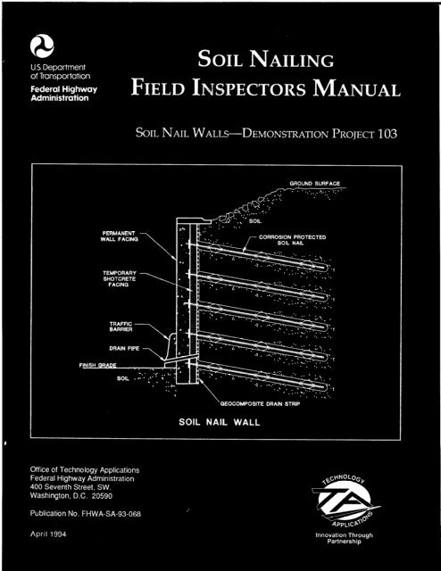
Soil nail retaining wall construction typically involves the following six steps, as shown in<br />
figure 1:<br />
Step 1. Excavate a small height cut.<br />
Step 2. Drill hole for nail.<br />
Step 3. Install and grout soil nail tendon.<br />
Step 4. Place geocomposite drain strips, initial shotcrete layer, and install bearing<br />
plates and nuts.<br />
Step 5. Repeat process to final grade, and<br />
Step 6. Place final facing (on permanent walls).<br />
Note:<br />
Steps 3 and 4, order <strong>of</strong> nail and shotcrete installation, may be reversed.<br />
Soil nailing is used to retain vertical, battered, or stepped excavations. Typical details <strong>of</strong> these<br />
wall types are shown in figures 2, 3, and 4. Soil nails are bonded along their full length and are<br />
not constructed with a permanent unbonded length as are tieback anchors. Test nails are<br />
constructed with a temporary unbonded length that is backfilled with grout after testing is<br />
completed.<br />
Soil nail wall construction is sensitive to ground conditions, construction methods, equipment,<br />
and excavation sequencing. Soil nailing cannot be used in all types <strong>of</strong> ground. For soil nail<br />
walls to be most economical, they should be constructed in ground that can stand unsupported<br />
on a vertical or steeply sloped cut <strong>of</strong> 1 to 2 m (3 to 6 feet) for at least one to two days, and that<br />
can maintain an open drill hole for at least several hours.<br />
1
6FTl HIGH<br />
STEP t. EXCAVATE SMALL CUT<br />
STEP 3. INSTALL AND GROUT NAIL<br />
1<br />
---- --<br />
2<br />
_-----<br />
3<br />
_--- --<br />
- - -.<br />
-’ - ---- --<br />
-,<br />
STEP 2. DRILL HOLE FOR HAIL<br />
STEP 4. PLACE DRAINAGE<br />
STRIPS, INITIAL SHOTCRETE<br />
LAYER 81 INSTALL BEARING<br />
PLATES/NUTS<br />
STEP 5. REPEAT PROCESS TO STEP 6. PLACE FINAL FACING<br />
FINAL GRADE (ON PERMANENT WALLS)<br />
Figure 1. Typical Nail Wall Construction Sequence.<br />
2
CURB AND GUTTER,<br />
IF SPECIFIED<br />
SHOTCRETE<br />
EXCAVATION<br />
SEQUENCE<br />
Figure 2.<br />
L FOOTING DRAIN<br />
SOIL NAIL (TYF)<br />
GEOCOMPOSITE DRAIN<br />
IF SPECIFIED<br />
Typical Section Through Vertical Wall.<br />
STRIP,
CIP F AClNQ \<br />
EXCAVATION<br />
SEQUENCE<br />
Figure 3.<br />
i FOOTING DRAIN<br />
SOIL NAIL (TYP)<br />
DRAIN STRIP.<br />
Typical Section Through Battered Wall.<br />
4
UPPER WALL<br />
CIP FACING ----,<br />
-.-<br />
- -! \.<br />
L FOOTING DRAIN<br />
SOIL NAIL (TYP)<br />
GEOCOMPOSITE<br />
DR DRAIN STRIP,<br />
VARIES<br />
IF SPECIFIED I<br />
VARIES<br />
Figure 4. Typical Section Through Stepped Wall.<br />
5
The following types <strong>of</strong> ground are considered favorable to soil nailing: naturally cohesive<br />
materials (silts and low plasticity clays that are not prone to creep); naturally cemented or dense<br />
sands and gravels with some real cohesion (due to fines) or apparent cohesion (due to natural<br />
moisture); and weathered rock. From a construction viewpoint, soil nailing is very adaptable and<br />
is therefore appropriate for mixed face conditions, such as competent soil over bedrock.<br />
Benefits <strong>of</strong> soil nailing include the following: ability to easily follow the building outline (i.e.,<br />
ability to zigzag’ as required); suitability <strong>of</strong> small construction equipment compared to alternative<br />
methods <strong>of</strong> construction; suitability for special applications and remedial work; ability to mobilize<br />
to a site quickly; elimination <strong>of</strong> need for soldier piles required with tieback walls; flexibility to<br />
allow for modifications during construction (e.g., nail locations can be moved to miss<br />
obstructions); and, compatibility with the usual constraints <strong>of</strong> operating in urban environments<br />
(e.g., need for minimum noise, small overhead clearance, etc.). Structural elements (soil nails<br />
and facing) and installation methods can easily be adapted, even during construction, to provide<br />
the most appropriate solution for specific site and ground conditions.<br />
The limitations <strong>of</strong> soil nailing include the following: inability to excavate where groundwater<br />
is a problem; difficulties associated with soil ravelling in cohesionless sands and gravels without<br />
use <strong>of</strong> special, expensive measures; problems associated with heavy concentrations <strong>of</strong> utilities,<br />
vaults or other underground obstructions behind the wall; and potential performance problems<br />
if used in expansive or highly frost susceptible soils. In addition, because wall performance is<br />
sensitive to the method <strong>of</strong> construction, optimal results typically can be achieved by experienced<br />
specialty contractors.<br />
The more common construction problems encountered on nail wall projects typically have<br />
involved encountering loose fill, granular soil with no apparent cohesion (e.g., “caving<br />
sands”), residual soils with remnant rock structure dipping adversely into the excavation,<br />
water, and man-made obstructions such as utility trenches. Other problems have involved<br />
contractor failure to construct the wall in accordance with the plans and specifications (e.g.,<br />
excessive over-excavation <strong>of</strong> lifts, elimination <strong>of</strong> nails, or use <strong>of</strong> poor grouting procedures)<br />
or mis-application <strong>of</strong> the method in ground conditions not suited to nailing. In a few cases,<br />
where significant excavation face sloughing has occurred without prompt remedial action,<br />
face collapses have occurred. Chapter 7 - Handling Difficult Ground - addresses the<br />
problems <strong>of</strong> those fewer soil nailing projects that happen to be built in poorer ground<br />
(whether by design or as a result <strong>of</strong> encountering unexpected site conditions).<br />
Note: Since their introduction in Europe approximately 20 years ago, “soil nails” have been<br />
installed in a wide variety <strong>of</strong> ground types, ranging from various types <strong>of</strong> soil to soils including<br />
cobbles and boulders to weathered and unweathered rock. While the term “ground” nail might<br />
technically be a more suitable “generic” term (like the term “ground anchor” that has been<br />
adopted for tiebacks), the term “soil nail,” or “soil nailing,” has become established as the<br />
commonly accepted “generic” term in use over the last 20 years, both in the U.S. and worldwide.<br />
Therefore, to be consistent with previously established practice, the term “soil nail” is used<br />
in this manual as a “generic” term that applies to nails installed in all types <strong>of</strong> ground.<br />
6
Basic Components <strong>of</strong> Soil Nail Walls<br />
Soil nail walls consist <strong>of</strong> three basic components: (1) the soil nails, (2) the drainage elements,<br />
and (3) the structural wall facing.<br />
Soil Nail<br />
A typical soil nail consists <strong>of</strong> a deformed steel reinforcing bar (generally Grade 60), also called<br />
a tendon, which is inserted into a predrilled, straight shafted, drillhole generally ranging from 100<br />
to 300 mm (4 to 12 inches) in diameter. After the nail tendon is inserted, the drillhole is<br />
completely filled with structural grout pumped under low-pressure via a tremie pipe (“open<br />
hole” installation). The grout “bonds” the nail tendon to the surrounding ground.<br />
Soil nails are typically installed by “open hole” methods using a variety <strong>of</strong> drilling equipment,<br />
usually augers. The open-hole method is used to install 80 to 90 percent <strong>of</strong> drilled and grouted<br />
soil nails. “Cased” or “auger cast” installation methods can be used when caving soil conditions<br />
are encountered. The installation method selected by the contractor will depend on soil/rock<br />
type, specified design adhesion values, groundwater conditions, site restrictions, structural require-<br />
ments such as total nail length and nail diameter, and equipment availability. Soil nail drilling<br />
and installation procedures are discussed in more detail in chapter 2 <strong>of</strong> part II. Chapter 7 -<br />
Handling Difficult Ground - also contains more detailed information on auger-cast and cased<br />
methods.<br />
The basic elements <strong>of</strong> a typical fully grouted production soil nail are shown in figure 5. The<br />
drilled length is the length <strong>of</strong> the nail drillhole; the soil nail length is the grouted tendon length,<br />
and the tendon length is the total length <strong>of</strong> the soil nail tendon.<br />
Test nails are constructed as.shown in figure 6 and incorporate an unbonded length to allow for<br />
testing. The unbonded length is that length <strong>of</strong> the tendon located in the upper portion <strong>of</strong> the<br />
drillhole that initially is not filled with grout. The unbonded length isolates the bonded portion<br />
<strong>of</strong> the test nail from the iacking system during testing. The tendon bonded length is the length<br />
<strong>of</strong> tendon that is bonded to the soil nail grout. For test nails, the test nail length is comprised<br />
<strong>of</strong> the unbonded length and the bonded length. The unbonded length <strong>of</strong> the test soil nail drillhole<br />
should be filled with grout promptly after the test is completed.<br />
The grouted hole diameter is commonly assumed to be equal to the nominal diameter <strong>of</strong> the<br />
drillhole. The actual final grout diameter may be larger than the diameter <strong>of</strong> the predrilled hole,<br />
due to oversizing <strong>of</strong> the hole by drilling action and/or by grout infiltration into surrounding<br />
permeable, granular soils. Grout infiltration is not likely in less permeable, fine grained soils.<br />
Centralizers are secured to the nail tendon at regular intervals to centralize the tendon in the<br />
drillhole and/or to provide a minimum specified grout cover. Centralizers consist <strong>of</strong> expanded<br />
PVC, steel, or other approved material that is not detrimental to the tendon steel.<br />
The bearing plate is attached to the nail head and transfers wall facing pressures to the nail. The<br />
bearing plate is attached to the nail with either a hex nut and beveled washer (most commonly)<br />
or a steel spherical seat nut, with the nut typically turned wrench tight.<br />
7
BEVELED<br />
WASHER<br />
\<br />
BEARING<br />
PLATE<br />
’ 1 I<br />
BEP MNG<br />
IUT I-<br />
STEEL TENDON<br />
SHOTCRETE OR GROUT BACKFILL<br />
(PLACED AFTER NAIL GROUT HAS SET)<br />
Figure 5. Typical Production Nail Detail.
NOTE1<br />
STEEL TENDON<br />
Figure 6. Typical Test Nail Detail.
The nail tendon consists <strong>of</strong> a deformed steel bar, available in various diameters (see table 1).<br />
Nail tendons should be installed as single units without couplers (unless couplers are allowed by<br />
the project specifications). Couplers are typically allowed for temporary extension <strong>of</strong> the nail<br />
tendon during testing. Welding is not permissible.<br />
Permanent soil nail systems require corrosion protection <strong>of</strong> the tendon. Corrosion protection<br />
requirements are discussed in chapter 4.<br />
TABLE 1. DEFORMED REINFORCING BARS<br />
Metric (SI) - AASHTO M31M/ASTM A6fSM (Grade 400)<br />
English - AASHTO M3YASTM A615 (Grade 60)<br />
Sizes and Dimensions<br />
Bar Size Nominal Dimensions<br />
Designation Diameter<br />
No. Area Weight<br />
SI English mm2 in.2 kg/m lb/ft mm in.<br />
10m 3 100 0.11 0.785 0.376 11.3 0.375<br />
15m 4 200 0.20 1.570 0.668 16.0 0.500<br />
20m 5 300 0.3-1 2.355 1.043 19.5 0.625<br />
25m 6 500 0.44 3.925 1.502 25.2 0.750<br />
30m 7 700 0.60 5.495 2.044 29.9 0.875<br />
35m 8 1000 0.79 7.850 2.670 35.7 1.000<br />
45m 9 1500 1.00 11.775 3.400 43.7 1.128<br />
55m 10 2500 1.27 19.625 4.303 56.4 1.270<br />
N/A 11 N/A 1.56 N/A 5.313 N/A 1.410<br />
N/A 14 N/A 2.25 N/A 7.650 N/A 1.693<br />
N/A 18 N/A 4.00 N/A 13.600 N/A 2.257<br />
N/A = Not available in metric size in U.S.<br />
Drainage Elements<br />
Drainage is considered a critical element, and is incorporated into all permanent walls and many”<br />
temporary walls.<br />
Face drainage is the type most commonly used and usually consists <strong>of</strong> prefabricated vertical<br />
geocomposite drainage strips installed from the top to the bottom as the excavation proceeds<br />
downward. The drainage strips are typically 300 to 450 mm (12 to 18 inches) wide, and are<br />
centered between the vertical nail columns. The strips are connected to weep hole outlet pipes<br />
and to a footing drain at the wall base. Drainage strips are used where small quantities <strong>of</strong> water<br />
are present or anticipated. They may not be suitable where large quantities <strong>of</strong> groundwater are<br />
encountered. With the use <strong>of</strong> vertical drainage strips, water must be captured and carried to the<br />
bottom <strong>of</strong> wall as construction progresses. This may cause a significant construction problem<br />
if large quantities <strong>of</strong> water are encountered. More detailed guidance on handling larger quantities<br />
<strong>of</strong> groundwater is presented in part II, chapter 7 - Handling Difficult Ground.<br />
10
A surface water collector ditch is usually placed behind the top <strong>of</strong> the wall to prevent surface<br />
run<strong>of</strong>f from either recharging the ground behind the wall or flowing over the top <strong>of</strong> wall.<br />
Structural Wall Facings<br />
Structural wall facings are required for face confinement, protection <strong>of</strong> the retained soil against<br />
weathering and erosion, and resisting lateral earth pressures.<br />
Soil nail retaining walls used on transportation projects are typically being constructed using a<br />
temporary shotcrete facing followed by a permanent wall facing consisting <strong>of</strong> cast-in-place (CIP)<br />
concrete, additional shotcrete, or precast concrete panels.<br />
Temporary Shotcrete Facing. A temporary shotcrete facing is placed to temporarily restrain<br />
and protect the exposed soil in the cut face. Typically, it consists <strong>of</strong> 75 to 100 mm (3 to 4<br />
inches) <strong>of</strong> shotcrete reinforced with a single layer <strong>of</strong> welded wire mesh (figure 7a). The<br />
temporary shotcrete facing is placed concurrently with each excavation lift.<br />
Permanent Wall Facings. Permanent wall facings may consist <strong>of</strong> full-thickness shotcrete (figure<br />
7b), CIP concrete over temporary shotcrete (figure 8), or precast concrete panels over shotcrete<br />
(figure 9). Although precast concrete panels are more typically used as architectural facings,<br />
some permanent precast structural facings have been used in Europe. Permanent facings<br />
consisting <strong>of</strong> CIP concrete (figure 8) are placed over the shotcrete following completion <strong>of</strong> the<br />
excavation to full height. The soil nail head/bearing plate must be structurally connected to the<br />
permanent wall, and the temporary shotcrete wall is sometimes considered sacrificial in the<br />
structural facing design. Both cast-in-place and precast concrete can provide a suitable<br />
architectural wall finish.<br />
Permanent shotcrete walls are constructed with either (1) the full-thickness shotcrete placed<br />
concurrently with each excavation lift (figure 7b), or, (2) a second full-height shotcrete layer<br />
placed over the initial shotcrete layer following the excavation to full depth (figure 7a). This<br />
type <strong>of</strong> wall generally has a total thickness <strong>of</strong> 150 to 300 mm (6 to 12 inches), and is reinforced<br />
‘with reinforcing bars or welded wire mesh.<br />
Architectural Fascias and Face Treatments. In many instances, architectural aesthetic<br />
requirements will call for a non-structural fascia to cover a permanent shotcrete or CIP facing.<br />
Such architectural fascias may consist <strong>of</strong> precast concrete panels, masonry stone, or masonry<br />
block.<br />
Architectural face treatments are commonly applied to CIP facings through the use <strong>of</strong><br />
commercially available form liners, boards, or other materials placed inside the face forms. Face<br />
treatment can be applied to permanent shotcrete facings by hand finishing and texturing, and<br />
coloring can be done by painting, staining or adding coloring agent to the shotcrete mix.<br />
11
FINAL FACING<br />
AS SPECIFIED<br />
WELDED WIRE FABRIC, HELD -<br />
OFF SOIL FACE WITH SPACERS<br />
AND PINS.<br />
MILD STEEL PLATE ~\<br />
STEEL TENDON TO PROTRUDE><br />
FROM SOIL FACE BEFORE<br />
SHOTCRETING. TENDON<br />
TO HAVE CENTRALIZERS.<br />
STEEL SPHERICAL SEAT --I<br />
NUT OR HEX NUT WITH<br />
BEVELED WASHER.<br />
Figure 7A. Typical<br />
MILD STEEL PLATE<br />
STEEL TENDON TO PROTRUDE ---‘-<br />
FROM SOIL FACE BEFORE<br />
SHOTCRETING. TENDON<br />
TO HAVE CENTRALIZERS<br />
STEEL SPHERICAL SEAT /<br />
NUT OR HEX NUT WlTH<br />
BEVELED WASHER.<br />
REINFORCING STEEL -<br />
---I F-- t<br />
P<br />
l<br />
SHOTCRETE FACING AS SPECIFIED<br />
SHOTCRETE OR GROUT BACKFILL<br />
/-<br />
STEEL TENDON WITH<br />
CORROSION PROTECTION<br />
- GEOCOMPOSITE DRAIN STRIP,<br />
IF SPEClflED<br />
GROUT<br />
I<br />
Temporary Shotcrete Facing Detail.<br />
--I t-<br />
/<br />
/<br />
FINAL SHOTCRETE FACING<br />
AS SPECIFIED<br />
SHOTCRETE OR GROUT BACKFILL<br />
GEOCOMPOSITE DRAIN STRIP,<br />
IF SPECIFIED<br />
STEEL TENDON WITH<br />
CORROSION PROTECTION<br />
7 GROUT<br />
Figure 76. Typical Permanent Shotcrete Facing Detail.<br />
12
CAST-IN-PLACE<br />
REINFORCED CONC-<br />
FINISH FACE<br />
-.-<br />
FINISHED GROUND LINE<br />
GUTTER \<br />
TEMPORARY SHOTCRETE FACING<br />
- - SOIL NAIL<br />
(TYP)<br />
FINISH QRADE ~EOCOMPOSITE -----<br />
DRAIN STRIP<br />
--L-w-,<br />
IF SPECIFIED<br />
--.<br />
=, i=cZ;;,- -<br />
i FOOTING DRAIN<br />
Figure 8. Typical Structural Cast-in-place Reinforced<br />
Concrete Facing Over Temporary Shotcrete.<br />
13
PRECAST CONCRETE PANELS<br />
PERMANENT<br />
SHOTCRETE FACING<br />
Figure 9.<br />
FINISHED GROUND Llm<br />
L FOOTING DRAIN<br />
--l<br />
GEOCOMPOSITE DRAIN STRIP,<br />
Typical Architectural Precast Concrete Panel Finish Face.
Applications <strong>of</strong> Soil Nailing<br />
Soil nailing is a cost effective alternative to conventional retaining wall structures when used in<br />
cut situations in ground suitable for nailing.<br />
Common nail wall applications include the following:<br />
l Temporary and permanent walls for building excavations.<br />
l Cut slope retention for roadway widening and depressed roadways.<br />
l Bridge abutments--addition <strong>of</strong> traffic lanes by removing end slopes from in front <strong>of</strong> existing<br />
bridge abutments.<br />
l Slope stabilization.<br />
l Repair or reconstruction <strong>of</strong> existing structures.<br />
Some examples <strong>of</strong> the above applications are shown in figures<br />
to P16.<br />
15<br />
lOand 1 and in photographs Pl
TEMPORARY SHOTCRETE FACING \<br />
SOIL TO BE REMOVED<br />
CAST-IN-PLACE REINFORCED<br />
CONCRETE FINISH FACE<br />
EXISTING ROADWAY<br />
ADDITIONAL ROADWAY<br />
FOOTING DRAIN<br />
Figure 10.<br />
EXISTING GROUND SURFACE --\<br />
HIGHWAY WIDENING AND<br />
TRAFFIC LANE ADDITIONS<br />
Soil Nail Wall Applications.<br />
16<br />
GEOCOMPOSITE DRAIN<br />
PERMANENT<br />
SOIL NAIL (TYP)<br />
STRIP,
CONVENTIONAL<br />
RETAINING WALL<br />
-1<br />
EXISTING ABUTMENT CAP - J;<br />
PERMANE!<br />
..-.. .-<br />
ABUTMENT PILES<br />
SOIL EXCAVATION<br />
AND BACKFILL<br />
TEMPORARY SHOTCRETE FACING<br />
TEMPORARY SHORING<br />
EXISTING BRIDGE<br />
WIDENING UNDER EXISTING BRIDGE<br />
Figure 11. Soil Nail Wall Applications.<br />
17<br />
I EXISTING<br />
WEEP HOLES (TYP.)<br />
PIER
Pl<br />
P2<br />
P3<br />
Pl. Wall with CIP facing and “fractured fin” face treatment placed over temporary shotcrete.<br />
New depressed freeway - Route 85, San Jose, CA.<br />
P2. Wall with precast panels and masonry block architectural fascia over CIP facing and<br />
shotcrete, located next to Aquatic Park. New interchange ramps - Route 37, Vallejo, CA.<br />
P3. Wall with CIP facing and “Rope band” face treatment over temporary shotcrete -<br />
Tonawanda Drive, San Diego, CA.<br />
P4. Lower nail wall with CIP facing supporting upper cantilever wall - I-405, Renton, WA.<br />
PS. Two-tier stepped wall with simulated stone masonry CIP facing - Route 89, vicinity <strong>of</strong><br />
Lake Tahoe, CA.<br />
P6. Wall with proprietary modular precast face panels - I-78, Allentown, PA.<br />
Ex&Aes <strong>of</strong> Permanent Soil Nail Walls - Highway Widening.<br />
18<br />
P4<br />
PS<br />
P6
P7<br />
P9<br />
Pll<br />
P7. Permanent shotcrete wall - painted with pigmented sealer. Shotcrete 225 mm (9<br />
inches) thick. Bridge abutment on spread footing - I-5, Tacoma, WA.<br />
PS. Permanent wall with CIP facing for new “turnaround” lanes. Bridge abutment is on<br />
drilled shafts - I-35, Laredo, TX.<br />
P9, 10. Before and after permanent nail wall - GW Parkway over I-495, Fairfax, VA.<br />
Bridge abutments are on spread footings on weathered rock.<br />
Pll, 12. Before and after permanent shotcrete wall painted with pigmented sealer. Shotcrete<br />
200 mm (8 inches) thick. Bridge abutment is on a single row <strong>of</strong> steel pipe piles -<br />
I-5, Swift Delta Interchange, Portland, OR.<br />
Examples <strong>of</strong> Permanent Soil Nail Walls - Widening Under Existing Bridges.<br />
19
P13<br />
P15<br />
Pl3,14 & 15. Replacement <strong>of</strong> failing old retaining wall. Residential city street-Seattle, WA.<br />
P13. Permanent soil nails installed through old wall.<br />
P14. Old wall demolished as new nail wall construction proceeds top-down. Nails plus<br />
initial shotcrete support the slope as old wall is removed.<br />
PH. Final hand-finished permanent shotcrete nail wall. Soil nailing allowed installation<br />
<strong>of</strong> new wall without disturbance to homes at top <strong>of</strong> slope.<br />
PM. Temporary nail shoring wall retains existing bridge end slope to allow excavation<br />
for enlarging existing bridge footing for seismic upgrade - I-10/280 Interchange,<br />
San Bernadino, CA.<br />
Examples <strong>of</strong> Soil Nail Walls - Wall Replacement and Temporary Shoring.<br />
20<br />
P14<br />
P16
Introduction<br />
PART I. PRECONSTRUCTION PREPARATION<br />
Chapter 2. Contract Documents<br />
Three general types <strong>of</strong> specifications are currently being used for soil nail wall construction:<br />
Performance Specifications, Contractor Design/Build Specifications, and Procedural<br />
Specifications. Each <strong>of</strong> these specifications assigns different requirements and responsibilities<br />
to the owner’s inspector and the contractor. The inspector should understand the type <strong>of</strong><br />
specification being used on the project.<br />
Performance Specifications<br />
When Performance Specifications are used, the responsibilities for the work and the risk are<br />
shared between the engineer (owner) and the contractor.<br />
The engineer determines the scope <strong>of</strong> the work, the nail design loads, nail spacings and locations,<br />
nail testing procedures, corrosion protection requirements (if any), facing design, and<br />
instrumentation and monitoring requirements. The contractor is responsible for the soil nail<br />
installation method, soil nail performance, excavation method, and excavation facing construction<br />
methods. This contracting method <strong>of</strong>ten pre-qualifies the soil nail specialty contractor, based on<br />
experience. This is desirable, because the experienced soil nail specialty contractor can best<br />
respond to localized changes in ground conditions and to other construction problems. The<br />
Performance Specification allows use <strong>of</strong> both the individual specialty contractor’s expertise and<br />
his proprietary equipment. Performance Specifications typically result in a better and more eco-<br />
nomical end product than do strict procedural (prescriptive or method) specifications. Permanent<br />
nail walls are <strong>of</strong>ten specified in this manner.<br />
When a Performance Specification is used, on a project designed by the owner, the contract<br />
documents will typically include the following:<br />
1.<br />
2.<br />
3.<br />
4.<br />
5.<br />
6.<br />
7.<br />
8.<br />
9.<br />
10.<br />
11.<br />
12.<br />
Provide, or m’ake available, the results <strong>of</strong> the geotechnical investigation.<br />
Specify submittals that the contractor must provide.<br />
Specify construction tolerances and minimum soil nail dimensions.<br />
Specify required soil nail design loads and design adhesion values.<br />
Specify excavation tolerances and sequencing, including the maximum allowable height <strong>of</strong><br />
excavation lifts.<br />
Specify material properties and requirements.<br />
Specify the type <strong>of</strong> corrosion protection required.<br />
Specify the type <strong>of</strong> finish facing required, including dimensions and reinforcing steel<br />
requirements.<br />
Specify the maximum time duration <strong>of</strong> finish cut face exposure prior to nail installation and<br />
closure with structural shotcrete.<br />
Specify the nail testing procedure(s) and acceptance criteria.<br />
Establish wall construction monitoring responsibilities and requirements, and<br />
Specify the methods <strong>of</strong> measurement and payment.<br />
21
The contractor’s main responsibilities are to:<br />
1. Fulfill the contract submittal requirements.<br />
2. Select the soil nail installation method.<br />
3. Comply with material specifications, construction tolerances, and minimum/maximum<br />
dimensions.<br />
4. Obtain and verify the soil nail load carrying capacity and adhesion values used in design.<br />
5. Complete construction excavations in accordance with the specifications.<br />
6. Install wall finish facings in accordance with the contract documents, and<br />
7. Perform the specified tests.<br />
The inspector’s responsibilities are to:<br />
1. Verify that construction tolerances, construction sequencing, and minimum soil nail<br />
2.<br />
requirements have been satisfied.<br />
Verify that drilling procedures are not causing excessive ground loss or subsidence.<br />
3. Verify compliance with the specified material properties and requirements.<br />
4. Verify that corrosion protection requirements have been satisfied.<br />
5. Verify that construction excavations are staged in accordance with the specifications.<br />
6. Verify that finish facings are constructed in accordance with the contract documents, and<br />
7. Observe, verify, and record the results <strong>of</strong> all construction testing.<br />
Contractor Design/Build Specifications<br />
A Contractor Design/Build Specification is very similar to a Performance Specification, except<br />
that it makes the Contractor responsible for both the design and construction <strong>of</strong> the soil nail wall.<br />
A Contractor Design/Build Specification details the soil nail wall system “end product” and<br />
makes the Contractor responsible for the soil nail design and installation method, the soil nail<br />
performance, the excavation method, and the excavation facing construction methods. This<br />
contracting method establishes the quality level <strong>of</strong> the work by requiring prequalification <strong>of</strong><br />
the soil nail specialty contractor, based on experience in design and construction. This type <strong>of</strong><br />
specification allows the use <strong>of</strong> both the contractor’s expertise in design and construction and his<br />
proprietary equipment.<br />
When a Contractor Design/Build Specification is used, the contract documents will typically<br />
include the following:<br />
1. Provide or make available the results <strong>of</strong> the geotechnical investigation.<br />
2. Specify submittals which the contractor must provide.<br />
3. Specify safety factors, material properties and requirements.<br />
4. Specify the level <strong>of</strong> corrosion protection required.<br />
5. Specify the finished face requirements.<br />
6. Specify wall alignment tolerances.<br />
7. Specify the percentage <strong>of</strong> nails to be tested, testing procedures and acceptance criteria.<br />
8. Establish wall construction monitoring requirements.<br />
9. Specify the methods <strong>of</strong> measurement and payment.<br />
22
The Contractor’s responsibilities are to:<br />
1. Design the wall.<br />
2. Comply with material specifications and wall tolerances,<br />
3. Obtain and verify the soil nail load carrying capacity and adhesion values used in design.<br />
4. Install the soil nails and facing in accordance with the finished face requirements and wall<br />
tolerances.<br />
The Inspector’s responsibilities are to:<br />
1. Verify compliance with the specified material properties and requirements.<br />
2. Verify that corrosion protection requirements have been satisfied.<br />
3. Verify that the wall finish face requirements are met.<br />
4. Verify that wall construction tolerance requirements have been satisfied.<br />
5. Observe, verify, and record the results <strong>of</strong> all soil nail tests.<br />
Procedural (Method) Specifications<br />
A procedural specification specifies &l details <strong>of</strong> design and construction, including the soil nail<br />
drilling method, soil nail type and dimensions, corrosion protection system, soil nail installation<br />
method, excavation procedures, and finish wall construction methods. Procedural specifications<br />
are also referred to as “prescriptive” or “closed” specifications. The responsibility <strong>of</strong> the<br />
contractor is to submit material certifications and build the soil nail system in strict accordance<br />
with the plans and specifications.<br />
When a procedural specification is used, the owner (and therefore the inspector), is fully<br />
responsible for the design and performance <strong>of</strong> the soil nail system, as long as the contractor has<br />
installed the nails in accordance with the specification requirements. Furthermore, the inspector<br />
and other personnel involved in the administration <strong>of</strong> the contract are responsible for directing<br />
the contractor’s work if changes are required. The owner assumes all the risk. Procedural<br />
specifications do not usually ensure a better job. Rather, they allow bidding by contractors not<br />
experienced with nail shoring wall work. Use <strong>of</strong> procedural specifications means that the<br />
potential for costly change orders is great.<br />
The procec@-al specification method is not generally recommended for contracting soil nail<br />
svstems.<br />
23
Introduction<br />
PART I. PRECONSTRUCTION PREPARATION<br />
Chapter 3. Know Your Design<br />
The inspector should have a basic understanding <strong>of</strong> the soil nail wall design prior to construction.<br />
This understanding should include a working knowledge <strong>of</strong>:<br />
l The contract type (i.e., performance specification, contractor design/build, or procedural<br />
specification). (See chapter 2)<br />
l The intended application <strong>of</strong> the soil nailing system (Le., permanent versus temporary<br />
construction). (See chapter 1)<br />
l The geometry <strong>of</strong> the soil nails and wall facing. (See this chapter.)<br />
l The subsurface conditions for which the soil nails were designed (i.e., what soil/rock and<br />
groundwater conditions are anticipated). (See this chapter.)<br />
l The planned construction sequence and its expected effects on the soil nail wall system. (See<br />
this chapter.)<br />
l The anticipated “stand-up” time for excavation faces. (See this chapter.)<br />
Understanding the soil nail wall design will aid the inspector in performing his/her duties, and<br />
in recognizing and dealing with changes in subsurface conditions and with any contractual<br />
problems that may develop during construction. A pre-construction meeting <strong>of</strong> the wall<br />
designer, the site inspector, and the contractor’s superintendent is strongly encouraged.<br />
Geometry <strong>of</strong> the Soil NaiI and Soil Nail Wall System<br />
The inspector should be familiar with the construction dimensions, geometry, and specified<br />
tolerances <strong>of</strong> the soil nail system.<br />
Usually, some sort <strong>of</strong> system for identifying each soil nail will be included in the plans. If such<br />
a system is lacking, the inspector should develop one. In the event the inspector has to develop<br />
his/her own identification system, this should be done on the nail layout on the plans and not<br />
on a separate worksheet. It is particularly important that the descriptions <strong>of</strong> the locations <strong>of</strong> the<br />
test nails relate directly to the information on the contract plans. This is necessary so that when<br />
communicating with others, (particularly the designer), and especially when communicating by<br />
phone, all parties know the location <strong>of</strong> the test nail in relation to the nearest test borings. In the<br />
absence <strong>of</strong> a specific identification number (I.D. No.) on the plans, references to specific wall<br />
stations and elevations are appropriate for describing the production and test nail locations.<br />
Additional items that should be noted include:<br />
l Any variance between the actual ground surface elevations along the wall line and those<br />
shown on the plans. This check should be made well in advance <strong>of</strong> the wall contractor<br />
mobilizing to the site. Any deviations should be brought to the immediate attention <strong>of</strong> the<br />
project engineer and designer so that the wall can be redesigned (if necessary) prior to the<br />
wall contractor starting construction. This Acrion will help prevent a subsequent claim dispute<br />
and/or construction delay.<br />
24
l Any slope above the wall that should be cut to grade prior to excavation.<br />
l Right-<strong>of</strong>-way limitations. Normally, soil nails will not be allowed to extend beyond the right-<br />
<strong>of</strong>-way unless there is a construction or permanent easement.<br />
l Location <strong>of</strong> all utilities or other known obstructions in the ground that could affect or be<br />
affected by soil nail construction.<br />
l Horizontal and vertical spacing <strong>of</strong> soil nails.<br />
l The maximum allowable height <strong>of</strong> each staged lift <strong>of</strong> excavation.<br />
l Any limits placed on the mass excavation adjacent to the wall excavation.<br />
l The maximum time allowed for shotcrete closure <strong>of</strong> finish wall line excavations.<br />
l Minimu= soil nail length; minimum drillhole diameter; hole inclination; corrosion protection<br />
requirements; tendon steel grade and diameter; and required grout cover.<br />
Soil/Rock and Groundwater Conditions<br />
Before construction begins, the inspector should review the project geotechnical report and, if<br />
possible, discuss the anticipated ground conditions with the geotechnical designer. The following<br />
specific items should be noted:<br />
l The soil/rock types expected to be encountered during construction. For example: cohesive<br />
(clay) soils versus cohesionless (sand) soils; fractured versus massive soil/rock structure; nail<br />
soil-grout adhesion values specified or anticipated, etc.<br />
l Expected stand-up time for the anticipated soil/rock types.<br />
l Expected groundwater conditions.<br />
l The boring logs and subsurface pr<strong>of</strong>ile developed from the geotechnical investigation.<br />
l Construction considerations outlined in the geotechnical report or deemed most important by<br />
the designer in relation to soil nail installation and retaining wall construction.<br />
Especially noteworthy are any special conditions unique to the site that might affect soil nail<br />
construction. Examples <strong>of</strong> such conditions follow:<br />
l Variable groundwater elevation in the soil pr<strong>of</strong>ile.<br />
l Visual evidence <strong>of</strong> landslide or slope stability problems.<br />
l Presence <strong>of</strong> distinctly different ground conditions at the site (i.e., clays versus sands versus<br />
cobbles and boulders, versus weathered or unweathered rock).<br />
l Potential for caving or sloughing <strong>of</strong> soils.<br />
l Possible presence <strong>of</strong> obstructions such as buried structures, piles, or utilities that could hinder<br />
soil nail installation.<br />
l Structures close to the excavation that could be damaged by any excavation-related ground<br />
movement.<br />
l Zones <strong>of</strong> weak or loose soils. This includes surficial fills that may be in a loose condition.<br />
l Swelling (expansive) or frost-susceptible soils.<br />
With this information in mind, the inspector will know what to expect, and can verify the<br />
geotechnical design conditions in the early stages <strong>of</strong> construction. The stability <strong>of</strong> the soil nail<br />
wall could be jeopardized by site conditions that vary substantially from those assumed<br />
during design. The design engineer should be contacted as soon as possible if unexpected<br />
ground conditions are encountered. In addition, verifying the assumed geotechnical design<br />
25
conditions and identifying and documenting differing site conditions will assist in resolution <strong>of</strong><br />
related disputes.<br />
Construction Sequencing<br />
,-<br />
Construction sequencing is especially important in soil nail wall construction. Soil nail wall<br />
systems are designed so that the excavation must proceed in staged lifts, with each lift defined<br />
by a single row <strong>of</strong> nails. Specifications for permanent soil nail walls typically require that each<br />
lift (including nail installation, shotcrete facing, and test acceptance) be completed prior to<br />
excavation and installation <strong>of</strong> an underlying row <strong>of</strong> soil nails. The specified excavation<br />
procedures and limitations presented in the contract documents must be adhered to at all times.<br />
- Failure to enforce these provisions could result in intolerable deformations <strong>of</strong> the wall under<br />
construction and possible failure or structural damage <strong>of</strong> the wall or existing ad.iacent<br />
structures located behind the wall.<br />
26
Introduction<br />
PART I. PRECONSTRUCTION PREPARATION<br />
Chapter 4. Corrosion Protection Considerations<br />
Longterm performance <strong>of</strong> soil nails depends on their ability to withstand corrosive attack from<br />
the environment. Corrosion protection is an integral and extremely important aspect <strong>of</strong> soil nail<br />
construction/inspection.<br />
The common methods <strong>of</strong> soil nail corrosion protection include encapsulation, epoxy coating,<br />
grout protection, or some combination <strong>of</strong> these measures. Each <strong>of</strong> these measures results in<br />
isolating the tendon from the corrosive environment to varying degrees. The degree and type<br />
<strong>of</strong> corrosion protection required will be noted in the plans and specifications. It should be<br />
emphasized that soil nail corrosion protection requirements are carefully considered during<br />
design, and that substitution <strong>of</strong> less effective corrosion protection should not be allowed<br />
without engineering approval.<br />
Encapsulated Corrosion Protection<br />
“Encapsulated” corrosion protection most commonly consists <strong>of</strong> encasing the tendon in a grout<br />
filled corrugated PVC (poly-vinyl chloride) or HDPE (high density polyethylene) tube. The<br />
annular space between the tendon and the corrugated tube, commonly specified as a minimum<br />
<strong>of</strong> 5 mm (0.2 inches), is filled with neat cement grout. Internal spacers are used to achieve the<br />
specified grout cover inside the encapsulation. Encapsulated corrosion protection is <strong>of</strong>ten referred<br />
to as “double” corrosion protection. Specifications most commonly require the encapsulation<br />
to be fabricated by the tendon supplier at the factory, where better quality control can be<br />
achieved, prior to shipment to the job site.<br />
Epoxy Corrosion Protection<br />
Epoxy corrosion protection consists <strong>of</strong> a fusion-bonded epoxy coating applied to the tendon prior<br />
to shipment to the construction site. The minimum required thickness <strong>of</strong> epoxy coatings will<br />
typically be specified in the contract documents. A minimum thickness <strong>of</strong> 0.3 mm (12 mils or<br />
0.012 inch) is common. Bearing plates and nuts that will be encased in a structural wall facing<br />
will be protected by the concrete cover, and typically are not epoxy coated.<br />
Grout Corrosion Protection<br />
In this application, the Portland Cement grout surrounding the nail tendon within the drillhole<br />
is relied upon to provide the necessary corrosion protection. This is usually acceptable only for<br />
short-term temporary applications in non-aggressive ground.<br />
27
P17 P20<br />
P18<br />
P19<br />
(Note: Photos P17, P18, and P19<br />
illustrate good practice. Photos P20 and<br />
P21 illustrate poor practice.)<br />
P17. Encapsulated corrosion protection. Note corrugated PVC tube. PVC centralizers are not<br />
shown, but would be placed on corrugated sheath prior to inserting nail into drillhole.<br />
P18. Epoxy corrosion protection. Note epoxy coated tendon and PVC centralizers. Note good<br />
centralizer design and fastening to tendon - allowing unobstructed grout flow around<br />
centralizers.<br />
P19. Properly stored epoxy corrosion protected tendons. Also note the additional 1 m (3 foot)<br />
long encapsulation at the top <strong>of</strong> nail. This is to provide extra corrosion protection vicinity<br />
<strong>of</strong> the nail/wall facing connection (Caltrans detail).<br />
P20. Improperly centered tendon inside field fabricated encapsulation. Factory fabrication<br />
recommended for better quality control.<br />
P21. Excessive use <strong>of</strong> duct tape to fasten centralizer to tendon. This will obstruct grout flow.<br />
Nail Corrosion Protection.<br />
28<br />
P21
Introduction<br />
PART II. CONSTRUCTION INSPECTION<br />
Chapter 1. Field Quality Control <strong>of</strong> Materials<br />
Quality control <strong>of</strong> construction materials is necessary to obtain a final product consistent with<br />
the contract specifications.<br />
Materials Control on the Project<br />
The quality <strong>of</strong> all materials used on the job is controlled by one or a combination <strong>of</strong> the<br />
following procedures:<br />
l Visual examination on the job for defects in workmanship, contamination, or damage from<br />
handling.<br />
l Certification by the manufacturer or supplier that the materials comply with the specification<br />
requirements.<br />
l Laboratory testing <strong>of</strong> representative samples from materials actually delivered to the job, or<br />
set aside for shipment.<br />
The last procedure requires that appropriate samples be obtained in accordance with the contract<br />
specifications. Also, once he/she has accepted the sampled materials, the inspector is responsible<br />
for ensuring that additional materials delivered to the site are consistent with the materials that<br />
were sampled. All materials delivered to the site should be visually examined. Any damaged<br />
or defective materials should be rejected immediately.<br />
The steel components (which include the soil nail tendons, bearing plates, nuts, washers and<br />
facing reinforcing steel) and the centralizers and drainage materials are usually accepted on the<br />
basis <strong>of</strong> satisfactory Mill Test Certificates. The properties <strong>of</strong> the steel listed on the test<br />
certificates should be checked for conformance to the specifications. The inspector should also<br />
verify that the nail tendon centralizers have been fabricated with the specified material and are<br />
<strong>of</strong> the correct diameter. Geocomposite drainage materials and drainage piping are usually<br />
accepted based on the manufacturers’ certification and product labelling.<br />
Soil nail grout and facing shotcrete typically are accepted on the basis <strong>of</strong> engineer approval <strong>of</strong><br />
the mix designs. Additives, such as retarders, accelerators, reinforcing fibers, or air entraining<br />
agents, must be pre-approved. Compressive strength tests will usually be specified to further<br />
ascertain acceptibility <strong>of</strong> materials at the job site. In addition, the shotcrete nozzleman may be<br />
required to complete test panels prior to his/her being approved for site work.<br />
Field Mandling and Storage <strong>of</strong> Soil Nail Tendons<br />
Soil nail tendons should be handled and stored in a manner that prevents damage or corrosion.<br />
The inspector should verify contractor care in unloading and storing the nail tendons.<br />
29
Storage should be as recommended by the manufacturer, away from construction traffic, and in<br />
a protected location. Epoxy coated or encapsulated (double) corrosion protected tendons must<br />
be stacked with care to prevent damage to the epoxy coating or corrugated encapsulation.<br />
Inspection <strong>of</strong> Corrosion Protection<br />
Usually, corrosion protected tendons (encapsulated or epoxy coated) will be delivered to the site<br />
completely assembled. Upon delivery <strong>of</strong> the tendons, the corrosion protection should be checked<br />
for compliance with the contract specifications. In addition, it is recommended practice to check<br />
a representative number <strong>of</strong> encapsulated tendons for voids in the grout fill placed in the annular<br />
space between the tendon and the corrugated tube. This check can be accomplished by lightly<br />
tapping the encapsulation with a steel rod and listening for hcllow sounds that indicate voiding.<br />
Suspected voids should be exposed to assess their seriousness. Additionally, the exterior <strong>of</strong><br />
epoxy coatings or corrugated encapsulation should be visually examined for damage, both upon<br />
delivery and prior to insertion into the soil nail drillhole. Bare spots cannot be tolerated, as<br />
even the smallest pinholes in corrosion protection coatings can result in severe corrosion in<br />
the presence <strong>of</strong> aggressive ground conditions. A light amount <strong>of</strong> rust on uncoated tendons is<br />
normal and will not affect their function. Pitting <strong>of</strong> uncoated tendons is cause for rejection, and<br />
the inspector should have the ability to distinguish between surface rust and pitting. Damage like<br />
abrasion, kinks, welds and weld splatters, cuts, and nicks will impair the proper performance <strong>of</strong><br />
the tendon and is cause for rejection. Damaged or improperly constructed corrosion<br />
protection is unacceptable. Inadequate corrosion protection should either be satisfactorily<br />
repaired, or rejected and removed from the site. All field repairs to corrosion protection should<br />
be completed in accordance with the appropriate manufacturer’s recommendations.<br />
Storage <strong>of</strong> Cement<br />
Cement to be used in grout should be kept dry and stored away from construction traffic and in<br />
a protected location. Cement that has become caked or lumpy should not be used. Aggregates<br />
used for on-site batching should be stored in a way that prevents segregation or the inclusion <strong>of</strong><br />
foreign materials.<br />
Storage <strong>of</strong> Reinforcing Steel<br />
Reinforcing steel should be carefully handled, and should be stored in a protected location on<br />
supports that will protect the steel from contact with the ground. Heavy corrosion or pitting <strong>of</strong><br />
the steel should be cause for rejection by the inspector. Light rust, that has not resulted in<br />
pitting, is acceptable.<br />
Storage <strong>of</strong> Drainage Materials<br />
Geocomposite drainage materials should be provided in rolls wrapped with a protective covering<br />
and stored in a manner that protects the fabric from dirt, debris, and shotcrete rebound. Extended<br />
exposure to direct sunlight (ultra-violet light) should be avoided.<br />
30
Field Quality Control <strong>of</strong> Materials Checklist<br />
Cl For steel components, centralizers, and drainage materials, obtain samples for testing (when<br />
specified) and check all Mill Test Certificates for compliance with the specifications.<br />
Cl Visually check all soil nail tendons and reinforcing steel for damage and defects upon<br />
delivery and prior to use.<br />
Cl Visually check epoxy coated or encapsulated tendons for compliance with the specifications<br />
and for any damage to the corrosion protection.<br />
Cl Confirm mix design compliance <strong>of</strong> soil nail grout and facing shotcrete.<br />
q When specified, take grout (cubes) and/or shotcrete samples (test panels and cores) for<br />
testing.<br />
Cl Verify compliance <strong>of</strong> geocomposite drainage materials with the contract plans/specifications.<br />
Cl Verify adequacy <strong>of</strong> field storage <strong>of</strong> construction materials to prevent damage or degradation.<br />
31
Introduction<br />
PART II. CONSTRUCTION INSPECTION<br />
Chapter 2. Construction Monitoring<br />
Quality Assurance/Quality Control (QA/QC) monitoring includes verifying that: 1) construction<br />
is being performed in accordance with plans and specifications; 2) admissible excavation heights<br />
are not exceeded; 3) boreholes have not caved; 4) nail tendons are <strong>of</strong> the right size and<br />
composition; 5) corrosion protection systems are in compliance; 6) grouting, installation <strong>of</strong> rebar<br />
and mesh, and shotcrete are in compliance; and 7) nail pullout testing meets specifications.<br />
Normally, grout cubes and shotcrete cores are taken for strength testing <strong>of</strong> permanent walls. Ar,<br />
essential part <strong>of</strong> the QA/QC process is monitoring <strong>of</strong> the material being excavated and drilled.<br />
The resulting information will assist in making design modifications should the material prove<br />
different from that on which the design was based.<br />
Soil nail retaining walls typically are constructed in staged lifts using “top-down” construction<br />
with each lift completed to closure (i.e., with nail testing and shotcrete facing completed) prior<br />
to excavation <strong>of</strong> underlying lifts. Typically, the sequencing for each lift will consist <strong>of</strong><br />
excavation to finish wall, nail installation, and facing closure. It is the inspector’s overall<br />
responsibility to ensure that all construction and testing for each lift has been completed in<br />
accordance with .the contract specifications and drawings.<br />
If a performance or design/build specification is used, it is the contractor’s responsibility to select<br />
a soil nail installation method that will develop the required soil nail design adhesion capacity.<br />
However, since only a percentage <strong>of</strong> the nails will be tested (unlike tieback walls where<br />
every tieback is tested), it is very important that consistent and similar construction<br />
methods be used for all soil nails. Therefore, the inspector must accurately observe and<br />
document the installa& conditions and methods <strong>of</strong> each soil nail.<br />
Soil/rock and groundwater conditions encountered during drilling should be recorded for<br />
each soil nail on the Soil Nail Installation Form presented in appendix A. Soil nail<br />
installation conditions should be summarized on the Soil Nail Installation Summary Form<br />
presented in appendix A. Examples <strong>of</strong> completed forms are presented in appendix B.<br />
Reference 3 is recommended as an aid in identifying soil types.<br />
Ultimate or verification tests may be part <strong>of</strong> a performance specification. These tests, which<br />
are discussed in greater detail in the next chapter, are used to verify that the contractor’s drilling<br />
and installation method(s) will produce a soil nail that will develop the adhesion capacity<br />
necessary to safely carry the design load.<br />
Pro<strong>of</strong> testing will generally be specified for a certain number (typically up to 5 percent) <strong>of</strong><br />
production soil nails. During construction <strong>of</strong> production nails, the inspector should note any<br />
changes in the ground type, or methods, equipment, or drill operators from those previously used<br />
to construct successful verification or ultimate test nails. A change in ground type, methods,<br />
equipment, or operators may warrant additional ultimate or verification tests.<br />
32
The inspector should make daily inspections <strong>of</strong> the area adjacent to the soil nail retaining<br />
wail construction. Special attention should be given to the geometry and structural condition<br />
<strong>of</strong> adjacent structures, such as concrete curbs, asphalt pavement, bridge abutments, etc..<br />
Typically, the connections between the top <strong>of</strong> the nail wall and the adjacent structures will open<br />
or separate slightly as the excavation proceeds, due to normal deformation <strong>of</strong> the ground toward<br />
the excavation. If the separations enlarge excessively, or rapidly increase in size, adverse<br />
wall deformations are indicated, and the design engineer and contractor must be<br />
immediately apprised <strong>of</strong> the situation.<br />
Quite <strong>of</strong>ten, tension cracks will form in the ground surface located immediately behind the top<br />
<strong>of</strong> the nail wall excavation. These cracks should be monitored, and the contractor and design<br />
engineer contacted, if displacements become excessive, or rapidly increase in size. Typically,<br />
surface tension cracks will either be hairline or open to a maximum <strong>of</strong> approximately 2 to 3 mm<br />
(l/16 to l/8-inch) for low height walls, say less than 6 m (20 feet). Larger tension cracks may<br />
be observed in taller walls. Water should not be allowed to enter tension cracks.<br />
Reconnaissance <strong>of</strong> the area behind the top <strong>of</strong> the retaining wall will also provide an assessment<br />
<strong>of</strong> surface water run<strong>of</strong>f/drainage conditions and erosion potential. Surface drainage above the<br />
wall should be controlled and routed away from the wall, and erosion potential eliminated,<br />
prior to initiation <strong>of</strong> the excavation. Remediation <strong>of</strong> adverse surface water run<strong>of</strong>f and/or<br />
erosion problems is difficult to implement once the excavation has been started.<br />
<strong>On</strong> some projects, construction monitoring devices and instrumentation, such as slope<br />
inclinometers, surface survey points, load cells, or strain gauge installations, may be required.<br />
If so, these requirements will usually be covered in the plans and specifications.<br />
Excavation<br />
The two types <strong>of</strong> excavation that generally occur during construction <strong>of</strong> a soil nail wall are:<br />
1) mass or general excavations conducted to provide equipment access and general site grading,<br />
and; 2) excavations required for construction <strong>of</strong> the soil nail wall, i.e., excavation to the plan<br />
finish wall line (“neat line”). Occasionally, use <strong>of</strong> a stabilizing or buffer berm, during nail<br />
installation, subsequently followed by excavation to finish wall line, will be required to maintain<br />
excavation face stability. This method is discussed in chapters 6 and 7. During mass or general<br />
excavation, the inspector must verify that the excavation does not encroach upon the partially<br />
completed soil nail wall to the extent that the stability <strong>of</strong> the wall is adversely affected.<br />
The contractor is responsible for completing the excavation to neat line and grade, and the<br />
inspector should verify compliance. Deviations from the specifications should be brought to the<br />
attention <strong>of</strong> the contractor, and remediation completed prior to placement <strong>of</strong> the finish facing.<br />
Conditions such as overbreaks, or sloughing <strong>of</strong> the cut face, as well as the protrusion <strong>of</strong> cobbles<br />
or boulders beyond the line <strong>of</strong> the cut face, must be addressed by the contractor. Limited<br />
overbreaks can typically be backfilled with shotcrete, placed at the same time as facing shotcrete.<br />
It is recommended that acceptable methods for handling excavation overbreak problems be<br />
determined prior to actual construction, preferably during the preconstruction meeting.<br />
The inspector should ascertain that open finish wall excavations are limited to the size that can<br />
be closed with shotcrete facing within the time restraints specified in the contract documents, and<br />
33
consistent with the observed stand-up time <strong>of</strong> the soil/rock. Finish excavation cut face exposures<br />
that will not receive shotcrete facing within the specified time limit must be stabilized by<br />
berming soil back up against the exposed face, placing a temporary shotcrete flashcoat, or other<br />
approved acceptable method.<br />
<strong>On</strong> occasion, groundwater may be encountered during excavation to the neat line. A discussion<br />
<strong>of</strong> groundwater implications and control is presented in chapters 6 and 7.<br />
Soil Nail Hole Drilling<br />
The soil nail drillholes should be located as shown on the plans. The drill normally will be<br />
oriented perpendicu!ar to the wall face, and the drill steel should be inclined downward at an<br />
angle <strong>of</strong> inclination within the allowable tolerances noted on the plans. Generally, the angle <strong>of</strong><br />
the drill mast, (as measured with a magnetic angle tool), is used to check the angle <strong>of</strong> the<br />
drillhole. Allowable inclination tolerances <strong>of</strong> f 3 degrees are common. At locations where, to<br />
avoid obstructions, the nail drillhole has to be angled differently than the orientation shown on<br />
the plans, the wall des!gner should be contacted immediately to determine if any design changes<br />
are necessary. The specified minimum diameter and length should be verified for each nail<br />
drillhole.<br />
Drill Rigs<br />
Most soil nails are installed using small hydraulic, track-mounted drill rigs. These rigs are<br />
mostly <strong>of</strong> the rotary/percussive type that use section augers or drill rods. The rigs can work <strong>of</strong>f<br />
benches as narrow as 5 m (17 feet), but are more productive if benches are 7 m (25 feet) wide,<br />
or more.<br />
The rigs are generally operated by one operator and one or two tenders. The number <strong>of</strong> tenders<br />
used is based on the weight <strong>of</strong> the augers or drill rods, and the location and orientation <strong>of</strong> the<br />
holes.<br />
For deeper soil nail excavations that require longer nail lengths, larger hydraulic-powered track-<br />
mounted rigs with continuous flight augers may be used. These rigs have the advantage that they<br />
can drill the entire length <strong>of</strong> the nail drillhole in a single pass without having to add sectional<br />
augers. Their main disadvantages are that they have a large mobilization cost, and require a<br />
much wider work bench than the smaller, more common drill rigs.<br />
Drill Methods<br />
The method <strong>of</strong> drilling selected by the specialty contractor will depend on the site and ground<br />
conditions and owned drill equipment, but is most frequently open hole drilling. Open hole<br />
drilling is used to install about 80 to 90 percent <strong>of</strong> all soil nails. Augering is the method most<br />
commonly used to construct open holes, with diameters generally ranging from 1OOmm to<br />
300mm (4 to 12 inches). The most common grouting method used with open hole drilling is the<br />
low pressure tremie method.<br />
Another less common open hole drilling method is the rotary-percussive method, which displaces<br />
soil by drilling and driving drill rods.<br />
34
Drillholes in soil should not be allowed to remain open for longer than the time stated in the<br />
specifications (if specified), unless approved otherwise by the design engineer. The longer the<br />
hole is left open, the greater the risk <strong>of</strong> caving or destressing <strong>of</strong> the soil.<br />
A mirror or high intensity light should be used, just prior to tendon installation, to inspect<br />
the hole for cleanliness. A practical point is that use <strong>of</strong> a mirror to inspect drillholes only works<br />
well on bright sunny days. A high intensity light (minimum 500,000 to l,OOO,OOO candlepower)<br />
works well anytime, and is the recommended inspection tool. Excessive slough ‘should be<br />
removed, either by redrilling <strong>of</strong> the hole, or by cleaning with a tool, if feasible. An alternative<br />
drilling method should be proposed by the specialty contractor, if sufficient slough cannot be<br />
removed.<br />
Cased hole methods cf drilling may be required in more difficult ground (i.e. ground with caving<br />
drillholes), and are used to install only an estimated 10 to 20 percent <strong>of</strong> drilled-in soil nails. This<br />
more expensive drilling method increases the cost <strong>of</strong> soil nail walls significantly, to the point<br />
where alternative wall construction methods may be more economical.<br />
Cased hole methods <strong>of</strong> drilling include the single tube rotary method, which involves drilling<br />
with a single tube (drill string) and flushing the cuttings outside the tube with air, water (provided<br />
the soils are not moisture sensitive, i.e. silty or clayey), or a combination <strong>of</strong> water and air. The<br />
“duplex” rotary method is another cased hole method sometimes used, and is similar to the single<br />
tube rotary method, except that it uses both an inner and outer casing, which allows drill cuttings<br />
to be removed through the annular space between the inner and outer casing. Duplex rotary<br />
methods can also include use <strong>of</strong> casing, with an inner drill stem <strong>of</strong> rods driving a rotary cutting<br />
bit. Cased drill hole sizes are generally 90 mm to 150 mm (3.5 to 6.0 inch) in diameter.<br />
Hollow-stem augers, with grout pumped through the auger stem as the auger is withdrawn, is<br />
another cased method (<strong>of</strong>ten referred to as “auger-cast”).<br />
Tendon Installation<br />
Prior to installation, the inspector should check each tendon to ensure that the tendon length,<br />
diameter, steel grade, centralizers, and corrosion protection (if required) are in accordance with<br />
the plans and specifications. The tendon must be inserted into the hole to the minimum specified<br />
length. The inability to do so indicates an unacceptable condition caused by caving/sloughing<br />
<strong>of</strong> the hole and/or insufficient drilled length.<br />
Tendons must be handled carefully to avoid damage. Single point lifting should only be allowed<br />
for short tendons that do not bend when handled in this manner. The tendon should be picked<br />
up in a way that will not cause damage to either the tendon or the corrosion protection. Longer<br />
soil nail tendons should be picked up at two or three equally spaced points.<br />
The inspector should ensure that centralizers (when required) are used to approximately center<br />
and fix the tendon in the hole. The centralizers should be stiff, and large enough to provide<br />
space for the minimum specified grout cover. Centralizers should be spaced closely enough to<br />
each other to keep the tendon from sagging and touching the bottom <strong>of</strong> the hole, but should not<br />
impede the free flow <strong>of</strong> tremied grout up the hole. Openings between the centralizer support<br />
arms should not be obstructed by materials used to secure the centralizer to the tendon,<br />
35
e.g., by excessive use <strong>of</strong> duct tape (see photo P21). A minimum centralizer spacing distance<br />
will usually be specified.<br />
When hollow-stem (“auger-cast”), or other cased methods are used, centralizers may not be<br />
required, if stiffer grout with a slump no greater than 200 mm (8 inches) is used. If this point<br />
is not covered in the specifications, the inspector should discuss it with the designer.<br />
The inspector should verify that the total specified length <strong>of</strong> the nail tendon has been inserted<br />
into the drillhole. After the tendon has been inserted into the drillhole, the inspector should mea-<br />
sure the protruding distance to ensure that the specified length has been achieved. If not, the<br />
tendon should be withdrawn and the hole cleaned or redrilled. Never allow the tendon to be<br />
driven or pushed beyond the drilled length, or cut <strong>of</strong>f. Either <strong>of</strong> these actions would result<br />
in an unacceptable installation.<br />
Grouting<br />
To minimize the chances <strong>of</strong> hole caving, open hole tremie grouting should take place as soon as<br />
‘practical after drilling and tendon insertion. If grouting takes place prior to tendon insertion, the<br />
tendon should be inserted immediately following grout placement.<br />
Grout should be injected by tremie pipe inserted to the bottom <strong>of</strong> the drillhole, so that the grout<br />
evenly and completely fills the hole from the bottom to the surface, and without air voids. The<br />
grout should flow continuously as the tremie pipe is withdrawn. The withdrawal rate should be<br />
controlled to ensure that the end <strong>of</strong> the tremie pipe is always below the grout surface.<br />
The inspector should record the number <strong>of</strong> grout pump strokes, and calculate the actual volume<br />
<strong>of</strong> grout placed as follows: Grout Volume equals number <strong>of</strong> pump strokes times the grout<br />
volume pumped per stroke (information typically supplied by the pump manufacturer).<br />
Alternatively, the grout volume per hole is estimated by dividing the number <strong>of</strong> holes filled per<br />
total cubic meters (cubic yards) <strong>of</strong> grout batched and pumped. The estimated hole volume is<br />
computed using this formula:<br />
Hole Volume = R: D2<br />
4<br />
x grouted length <strong>of</strong> drillhole (x = 3.14, D = drillhole diameter).<br />
The grout take is expressed as the volume <strong>of</strong> grout actually placed in the drillhole, divided by<br />
the estimated hole volume.<br />
When hollow stem auger methods are used, the contractor should not be allowed to reverse the<br />
auger rotation during extraction. This action forces soil to mix with the grout, thus reducing<br />
grout strength. The contractor may, however, make one or more quick reversals <strong>of</strong> the auger<br />
with the auger head still at the bottom <strong>of</strong> the hole, to release the nail tendon from the auger, prior<br />
to extracting the auger.<br />
Test nails require partial grouting <strong>of</strong> the nail drillhole in order to develop bonded and unbonded<br />
test lengths. The contractor is responsible for placing the grout to the specified test lengths, and<br />
the inspector should verify compliance. Typical methods for establishing the top <strong>of</strong> the test<br />
bonded length include placing a painted centralizer or piece <strong>of</strong> survey ribbon onto the tendon,<br />
at the desired point <strong>of</strong> grout termination (top <strong>of</strong> bonded zone), prior to insertion into the drillhole.<br />
36
A high intensity light can be used to aid in observing the grout placement. If auger-cast or other<br />
cased methods are used, the bonded length can be estimated during grouting by measuring the<br />
volume <strong>of</strong> grout placed, and can later be verified by measuring the unbonded length, using a rigid<br />
tape or a piece <strong>of</strong> measured rigid tremie pipe or reinforcing steel. As an alternative, the grout<br />
can be placed to the full length <strong>of</strong> the hole, and the unbonded length can either be flushed out<br />
before the grout has set, using water delivered via a garden hose or tremie pipe, or drilled out<br />
after the grout has set. Care should be exercised not to overflush and remove grout from the<br />
bonded zone. The specified unbonded length should be verified and remeasured, using a rigid<br />
tape, or a piece <strong>of</strong> measured rigid tremie pipe or reinforcing steel, prior to testing. Subsequent<br />
to testing and acceptance <strong>of</strong> the results, the unbonded length <strong>of</strong> - all test nails must be filled<br />
with grout. Voids should not be left in the ground.<br />
Structural Wall Facing and Drainage<br />
<strong>On</strong>ce the final wall line excavation and nail installation have been completed, the geocomposite<br />
drain strips and reinforcing steel are installed, and shotcrete is applied to the lines and grades<br />
specified in the contract documents. When required by site conditions (e.g., poor cut face stand-<br />
up time), the shotcrete facing may be placed before nails are drilled and installed (if proposed<br />
by the contractor and approved by the engineer). If this approach is taken, the wall designer<br />
must approve the contractor’s proposed details for drilling through the shotcrete facing (e.g.,<br />
blockouts, resteel, sleeve over nail through shotcrete, etc.).<br />
Generally, the geocomposite drain strips are placed vertically, at specified intervals. Some<br />
designs may also specify drainage strips placed horizontally at each shotcrete construction joint.<br />
Typical installation geometry for the geocomposite drain strips and example weep hole drain<br />
outlet and toe drain details are shown in figure 12. Drain strips must be continuous from the top<br />
to the bottom <strong>of</strong> the wall. Splices should be made with a minimum 300 mm (12-inch) overlap<br />
(or per specification or manufacturer’s recommendations) to assure that water flow is not<br />
impeded. Maintenance <strong>of</strong> drainage continuity and capacity is critical to the overall stability<br />
<strong>of</strong> the system and must not be jeopardized.<br />
Conventional shotcrete procedures are generally applicable, with the major exception being that<br />
each shotcrete lift must be applied against soil, rather than against a form board or existing<br />
concrete. The overlying cold joint must be cleaned prior to placement <strong>of</strong> the underlying lift <strong>of</strong><br />
shotcrete. Some specialty contractors attach temporary wood stops at the bottom <strong>of</strong> each<br />
shotcrete lift (see photos P33 and P34) to minimize time and labor required to clean the cold<br />
joint. The temporary wood stops are removed after the shotcrete has set. Acceptable methods<br />
for cleaning the shotcrete joint include washing with a combination <strong>of</strong> injected water and<br />
compressed air, blowing with compressed air, or sand blasting. Care should be taken not to<br />
erode the soil cut face below the cold joint.<br />
The most critical factor in ensuring a good quality shotcrete facing is a nozzleman who is<br />
experienced in gunning structural shotcrete. Specifications may require the nozzleman to<br />
complete a pre-qualification test panel (mock-up <strong>of</strong> the work to be completed) prior to beginni%g<br />
production work. Typically, core samples are taken from the test panel(s) and visual examination<br />
and compressive strength tests are performed. In addition, the specifications may require that<br />
compressive strength test panels be completed by the nozzleman and tested for compressive<br />
strength periodically throughout the project duration. The size <strong>of</strong> such “check” compressive<br />
37
strength test panels is typically 300 by 300 mm square by 100 to 150 mm thick (12 by 12 inches<br />
square by 4 to 6 inches thick).<br />
The following points summari ze some basic recommended practices for applying structural<br />
shotcrete facings:<br />
. The nozzle should be held perpendicular to the surface, except when shooting around<br />
reinforcing bars.<br />
l Optimum nozzle distance from the surface being shot against is<br />
Wet-mix: 0.6 to 1.5 m (2 to 5 feet)<br />
Dry-mix: 1 to 2 m (3 to 6 feet)<br />
. Shooting shall start at the bottom.<br />
. Voids shall not be left behind bars or steel mesh.<br />
l Control <strong>of</strong> alignment, grade, and thickness shall be determined by the contractor. Where sharp<br />
edges and accurate lines are required, these should be set out by screed boards, guide wires<br />
and/or depth spacers.<br />
Temporary shotcrete facings typically consist <strong>of</strong> 75 to 100 mm (3 to 4 inches) <strong>of</strong> wire mesh or<br />
fiber-reinforced shotcrete thickness, placed directly against the soil, as the excavation proceeds<br />
in staged lifts. <strong>On</strong>ce the excavation is bottomed, the permanent wall facing is built. Cast-in-<br />
place concrete, additional shotcrete, precast concrete panels, or other approved facings are used<br />
for the finish wall permanent facing.<br />
The inspector should verify that the following construction conditions are met, in accordance with<br />
the contract specifications and drawings, prior to shotcrete placement:<br />
l The geocomposite drainage materials have been installed at the locations and to the dimensions<br />
specified, and are connected with specified overlaps to ensure continuity <strong>of</strong> hydraulic flow, and<br />
have been secured to prevent excessive vibration during shotcrete placement.<br />
l The welded wire mesh or reinforcing steel has been installed at the locations and to the<br />
dimensions and overlaps specified. Particular care should be given to ensure that reinforcing<br />
steel is tied securely and is clean.<br />
l Construction joints are clean and acceptable for shotcrete placement.<br />
l The finish grade and line will be in accordance with the specifications.<br />
l The contractor is prepared to provide the necessary finish on the exposed shotcrete surface.<br />
l The shotcrete will be applied, and cut face closure will occur, within the specified time limits.<br />
l Construction equipment that can cause ground vibration detrimental to the shotcrete will not<br />
be allowed to pass close to the shotcreted face before the shotcrete has attained initial set.<br />
Nonconformances must be brought to the attention <strong>of</strong> the contractor, and corrected prior to<br />
placement <strong>of</strong> the wall facing.<br />
38
f<br />
/<br />
GEOCOMPOSITE DRAINAGE STRIP<br />
+ II + II + II + II + II<br />
II II II II<br />
/I<br />
II+<br />
II<br />
II+<br />
II<br />
IIf II+<br />
II<br />
II<br />
l---&d<br />
SPECIFIED<br />
SOIL NAIL WALL<br />
CONCRETE BARRIER<br />
DRAIN PIPE<br />
FINISHED GRADE --,<br />
+ NAIL LOCATIONS<br />
NOTE: HORIZONTAL DRAIN STRIPS<br />
SOMETIMES ALSO SPECIFIED AT<br />
EACH HORIZONTAL CONSTRUCTION<br />
JOINT BETWEEN SHOTCRETE LIFTS<br />
AND OR/ WHERE SEEPAGE ZONES<br />
ENCOUNTERED<br />
GEOCOMPOSITE DRAIN STRIPS<br />
TOE DRAIN OUTLET PIPE<br />
CONTINUOUS<br />
PERFORATED<br />
DRAIN PIPE<br />
SEE DETAIL<br />
GRADING PLANS<br />
FOOTING DRAIN<br />
GEOCOMPOSITE DRAIN STRIP<br />
FlLTER FABRIC<br />
HARDBOARD<br />
Figure 12. Examples <strong>of</strong> Wall Drain Details.<br />
39<br />
FILTER FABRIC
P22<br />
P22. Excavation <strong>of</strong> lift to finish wall line.<br />
P23. Note compact drill rig. Can operatk in limited width work area.<br />
P24. Drilling nail hole.<br />
P25. Completed drillhole.<br />
P26. Drillhole cleaning tool and high intensity light (minimum 500,000 to 1 million<br />
candlepower) for inspecting drillholes.<br />
Soil Nail Wall Construction.<br />
40<br />
P25<br />
P26
P27<br />
P28<br />
P29<br />
P27. Cleaning and inspecting drillholes prior to installing nail.<br />
P28. Scaled PVC tube used as measuring rod to measure drillhole and nail lengths.<br />
P29. Soil nail tendon installation. Note centralizers.<br />
P3O. Tremie pipe grout placement.<br />
P31. Installing prefab vertical geocomposite drain strips and welded wire mesh.<br />
P32. Prefab drain strips, shipped to job site in rolls.<br />
Soil Nail Wall Construction.<br />
41<br />
P30<br />
P31<br />
P32
P33 P36<br />
P34<br />
P35<br />
P33. Installing securing pins to support welded wire mesh prior to wall shotcreting. Also note<br />
smaller flat-headed nails used to secure drain strips to excavation face.<br />
P34. Applying shotcrete. Note application from bottom <strong>of</strong> lift upward. Also note temporary<br />
soil berm and wood stop at bottom <strong>of</strong> lift to keep shotcrete <strong>of</strong>f mesh overlap to next lift.<br />
P35. Proper technique for shotcreting top part <strong>of</strong> drillhole. Nozzleman inserts nozzle horn into<br />
mouth <strong>of</strong> drillhole to assure non-voided backfill and prevent dirt from being blown into<br />
hole.<br />
P36. Steel bearing plate, nut, and beveled washers connecting nail head to shotcrete face. Also<br />
note shear studs to connect to CIP facing.<br />
P37. Face form for CIP facing. Also note drain pipe outlets at wall base.<br />
P38. Drainage gutter installed behind top <strong>of</strong> wall.<br />
Soil Nail Wall Construction.<br />
42<br />
P37<br />
P38
P3Y P42<br />
P40<br />
P41<br />
P39. Nozzleman gunning prequalification test panels.<br />
P40. Nozzleman applying wall shotcrete. Blowpipe operator removing rebound.<br />
P41. Rough screeding shotcrete back to thickness-control guide wires,<br />
P42. Hand finishing with rubber float to apply final face texture.<br />
P43. Example <strong>of</strong> permanent nail wall with full thickness structural shotcrete, I-5 Tacoma, WA.<br />
P44. Completed wall after placement <strong>of</strong> traffic barrier and painting with pigmented sealer,<br />
I-5 Tacoma, WA.<br />
Shotcreting a Permanent Structural Shotcrete Wall.<br />
43<br />
P43<br />
P44
Excavation<br />
Construction Monitoring Inspection Checklist<br />
U Prior to start <strong>of</strong> any wall construction, check for any variance between the actual ground<br />
surface elevations along the wall line and those shown on the plans.<br />
q Frequently ascertain that stable excavation conditions are being maintained, both for general<br />
mass excavation and wall neat line face excavation. Make daily inspections <strong>of</strong> the ground next<br />
to the wall excavation.<br />
Cl Verify that excavations are constructed within specification tolerances <strong>of</strong> the design line and<br />
grade.<br />
0 For each excavation lift, verify that contractor is not overexcavating.<br />
Soil N&l Hole Drilling<br />
0 Document construction on the “Soil Nail Installation and Summary Forms” in appendix A.<br />
q Verify that the soil nail hole is drilled within acceptable tolerances <strong>of</strong> the specified alignment,<br />
length, and minimum diameter.<br />
Cl Verify that loss <strong>of</strong> ground or drillhole interconnection is not occurring.<br />
Tendon Installation<br />
0 Inspect open soil nail holes for caving or loose cuttings using a high intensity light.<br />
Cl Verify that tendons are inserted to the minimum specified length.<br />
q Verify that centralizers are installed at the specified intervals and will provide clearance for<br />
the minimum specified grout cover and that openings through the centralizer support arms are<br />
not obstructed.<br />
Cl Watch to make sure that workers handle and insert the tendons carefully to prevent damage<br />
to the corrosion protection.<br />
Grouting<br />
Cl Verify that grout is injected by tremie pipe starting at the bottom <strong>of</strong> the hole, and that the end<br />
<strong>of</strong> the tremie pipe always remains below the level <strong>of</strong> the grout as it is extracted.<br />
q Verify that grout continues to be pumped as the grout tube, auger, or casing, is removed.<br />
q Measure and record the volume <strong>of</strong> grout placed in the hole, and determine the “grout take”.<br />
Cl Verify that the contractor does not reverse the auger rotation while grouting by auger-cast<br />
methods, except as necessary to initially release the tendon.<br />
Cl Verify that “auger-cast” or “cased” nails have been installed with the specified tendon length<br />
grouted.<br />
q Verify that grout is batched in accordance with approved mix designs.<br />
0 Confirm that any required grout strength test samples have been obtained in accordance with<br />
the specifications. These are typically 50x50 mm (2x2 inch) grout cubes.<br />
q Verify the bonded and unbonded lengths <strong>of</strong> test nails.<br />
44
Structural Wall Facing and Drainage<br />
Cl Verify that the geocomposite drain strips and weep hole outlet pipes are installed as specified<br />
and that drain elements are interconnected and provide continuous drainage paths.<br />
Cl Verify that the reinforcing steel has been installed at the locations and to the dimensions<br />
specified. Particular care should be given to ensure it is tied securely and is clean.<br />
q Verify that wall finish line and grade will be in accordance with the plans and specifications.<br />
U Verify that shotcrete will be applied and cut face closure will occur within the specified time<br />
limits.<br />
Cl Verify that shotcrete is applied as specified, and in accordance with recommended good<br />
practice.<br />
Cl Verify that construction joints are clean and acceptable for shotcrete placement.<br />
Cl Verify that shotcrete is batched in accordance with the approved mix design.<br />
Cl Verify that shotcrete test panels (if specified) are prepared, cured, and transported to the<br />
testing lab in accordance with specifications.<br />
45
Introduction<br />
PART II. CONSTRUCTION INSPECTION<br />
Chapter 3. Nail Testing<br />
Soil nails are field tested to verify that the nail design loads can be carried without excessive<br />
movements and with an adequate safety factor for the service life <strong>of</strong> the structure. In addition,<br />
testing is used to verify the adequacy <strong>of</strong> the contractor’s drilling, installation, and grouting<br />
operations prior to and during construction <strong>of</strong> production soil nails. Therefore, the soil/rock<br />
conditions as well as the method, equipment, and operator used for installing production nails<br />
must be the same as those used for installing test nails. If ground and/or installation procedures<br />
change, additional testing may be required. It is typical practice to complete testing in each row<br />
<strong>of</strong> nails prior to excavation and installation <strong>of</strong> the underlying row. If inadequate test results<br />
indicate faulty construction practice or adhesion capacities less than required, the contractor<br />
should be required to alter nail installation/construction methods. In the event that required<br />
design adhesion capacities are still not achievable, redesign may be necessary.<br />
Testing criteria will be part <strong>of</strong> the specifications and may consist <strong>of</strong> “ultimate” and/or<br />
“verification” tests, which are conducted to validate the contractors installation methods and to<br />
verify compliance with the soil nail load carrying capacity and adhesion values used in design.<br />
These tests usually require loading to a maximum test load that includes the factor <strong>of</strong> safety<br />
assigned to the design soil adhesion and/or that results in pullout failure (i.e., inability to maintain<br />
constant test load without excessive soil nail movement). The number <strong>of</strong> tests will vary,<br />
depending on the size <strong>of</strong> project and the major different ground types in which nails will be<br />
installed. <strong>On</strong> smaller projects, one or two ultimate or verification tests are commonly conducted<br />
prior to beginning production nail installation, and then one or more additional such tests are<br />
<strong>of</strong>ten conducted in each major different ground type encountered as construction proceeds. A<br />
larger number <strong>of</strong> ultimate or verification rests may be specified for larger projects. Ultimate and<br />
verification tests are typically performed on “sacrificial” test nails.<br />
During production installation, “pro<strong>of</strong>” testing is conducted on a specified percentage (typically<br />
as many as 5 percent) <strong>of</strong> the total production nails installed. Some specifications allow pro<strong>of</strong><br />
testing to be performed on production nails that will be incorporated into the structure while other<br />
specifications require the pro<strong>of</strong>-tested nails to be extra “sacrificial” nails that will not be<br />
incorporated into the structure.<br />
Creep tests are typically performed as part <strong>of</strong> ultimate, verification, and pro<strong>of</strong> tests. The creep<br />
test consists <strong>of</strong> measuring the movement <strong>of</strong> the soil nail at constant load over a specified period<br />
<strong>of</strong> time. This test is done to ensure that the nail design loads can be safely carried throughout<br />
the structure’s service life (typically 75 to 100 years) without causing movements that could<br />
damage the structure.<br />
Nail testing is conducted by incrementally loading (and, if specified, unloading) the soil nail<br />
tendon and measuring the movement <strong>of</strong> the soil nail head at each load increment. Typically, the<br />
tendon movement reading is recorded just after the next load increment has been applied. The<br />
loading increments, the time that each load increment is held, and the number <strong>of</strong> measurements<br />
for each load increment are determined by the type <strong>of</strong> test being performed, and will be specified<br />
in the contract documents. If not specified, recommended practice is to obtain a tendon<br />
46
movement reading just after the load has been applied, and a second reading after the load has<br />
been maintained for a sufficient amount <strong>of</strong> time to ensure that tendon movement has stabilized.<br />
Testing procedures were not “standardized” at the time this manual was written and vary<br />
amongst different Highway Agencies. Check specifications for test procedures applicable<br />
to your praiect.<br />
Equipment for Testing<br />
Figure 13 and photo P45 shows a typical soil nail testing set up. A center hole hydraulic jack<br />
and pump are used to apply the test ioad to the tendon. The axis <strong>of</strong> the jack and the axis <strong>of</strong> the<br />
nail must be aligned to ensure uniform load.ing <strong>of</strong> the tendon. Typically, a jacking frame or<br />
reaction block is installed between the shotcrete or excavation face and the jack. The jacking<br />
frame should not react directly against the nail grout column during testing. <strong>On</strong>ce the jack is<br />
centered and aligned, an alignment load is applied to the jack to secure the equipment and take<br />
the “slack” out <strong>of</strong> the set-up. The jack load should not be permitted to drop below the<br />
alignment load during subsequent test loading. This could cause misalignment <strong>of</strong> the jacking<br />
set-up and result in misleading test results. The magnitude <strong>of</strong> the alignment load will affect test<br />
results. The alignment load should not be permitted to exceed 10 percent <strong>of</strong> the maximum test<br />
load. If higher alignment loads are required to support equipment, the contractor should provide<br />
alternative methods for externally supporting the equipment.<br />
Movement <strong>of</strong> the nail head is measured with at least one, and preferably two dial gauges<br />
mounted on a tripod or fixed to a rigid support that is independent <strong>of</strong> the jacking set-up and wall.<br />
Two dial gauges are recommended in order to provide an “average” reading, in case the loading<br />
is slightly eccentric due to imperfect alignment <strong>of</strong> the jack and tendon, and to provide a backup<br />
if one gauge malfunctions. The dial gauges should be aligned within 5 degrees <strong>of</strong> the axis <strong>of</strong> the<br />
nail, and should be zeroed after the alignment load has been applied. The dial gauge should be<br />
capable <strong>of</strong> measuring to the nearest 0.02 mm (0.001 inch). The dial gauge should be able to<br />
accommodate a minimum travel <strong>of</strong> the estimated elastic elongation <strong>of</strong> the test nail at the<br />
maximum test load plus 1 inch, or at least 50 mm (2 inches).<br />
A hydraulic jack and pressure gauge are used to apply and measure the load applied to the soil<br />
nail. It is recommended that the hydraulic jack have a minimum travel or “throw” <strong>of</strong> at least 150<br />
mm (6 inches). A center hole load cell may be added in series with the jack for use during creep<br />
tests. The hydraulic jack and pressure gauge (and load cell, if used) should be calibrated as a<br />
set. Recent calibration data for the jack, pressure gauge, and load cell must be obtained from<br />
the contractor prior to testing. The identification numbers on the field test equipment must match<br />
the identification numbers on the calibration data sheets. A typical calibration data sheet and<br />
graph for a hydraulic jack is presented in appendix A and completed samples are presented in<br />
appendix B .<br />
When load cells are used, care should be taken to ensure that the cell is properly aligned with<br />
the axis <strong>of</strong> the tendon and jack. Load cells are used mainly to detect small changes in load and<br />
allow load adjustment and maintenance <strong>of</strong> constant load holds during creep testing. As an<br />
example, assume that the load cell reads “440” once the creep test load is achieved. Maintaining<br />
the “440” reading on the load cell, through jack pressure adjustments, will ensure that a constant<br />
load is held throughout the creep test.<br />
47
.<br />
A<br />
.<br />
t<br />
J<br />
><br />
HYDRAULIC RAM<br />
____-----<br />
__-----<br />
____----- -_-----<br />
::.:.:.:.:::::.,.....:...,.,:<br />
.,...::.:.:.::::::<br />
,...,:<br />
\\ REFERENCE<br />
__----<br />
REACTION FRAME/PLATE<br />
SHOTCRETE FACING,<br />
-BULKHEAD OR GROUND<br />
v BEARING<br />
PLATES<br />
Figure 13. Typical Nail Test Setup.<br />
DIAL GAUGES<br />
ATTACHED<br />
TO SUPPORTS<br />
ON GROUND<br />
INDEPENDENT
P45. Typical testing setup. Note dial gauges, reference plate, load cell, centerhole hydraulic<br />
jack, reaction frame, and hydraulic pump (on ground).<br />
Types <strong>of</strong> Tests<br />
The maximum test load, the load increments, and the time that each load increment is held are<br />
determined by the type <strong>of</strong> test being performed. The loading schedule outlined in the contract<br />
specifications should be followed for each test type. In no case should the soil nail tendon be<br />
stressed to more than 80 percent <strong>of</strong> its minimum ultimate tensile strength for grade 150<br />
steel, or more than 90 percent <strong>of</strong> the minimum yield strength for grade 60 steel. Otherwise,<br />
an explosive failure <strong>of</strong> the steel can occur. The nail tendon manufacturer provides strength data<br />
for each size <strong>of</strong> soil nail tendon based on diameter and grade <strong>of</strong> steel. Personnel should always<br />
remain clear <strong>of</strong> the testing apparatus/nail tendon, since bar failure could occur at any time,<br />
particularly at higher test loads. Copies <strong>of</strong> standard forms for recording the load test data are<br />
provided in appendix A, and examples <strong>of</strong> completed forms are provided in appendix B.<br />
Ultimate Test<br />
Ultimate tests (if used) are performed on non-production, “sacrificial” soil nails, and provide the<br />
following information:<br />
l Determination <strong>of</strong> the ultimate adhesion capacity (if carried to pullout failure).<br />
8 Verification <strong>of</strong> the design adhesion factor <strong>of</strong> safety.<br />
l Determination <strong>of</strong> the soil nail load at which excessive creep occurs.<br />
49
A true “ultimate” test is performed by loading the soil nail until pullout failure takes place along<br />
the grout ground interface (pullout failure is the inability to maintain constant test load without<br />
excessive movement). Specifications will usually state a maximum test load at which the test<br />
can be terminated if pullout failure does not occur.<br />
Verification Test<br />
Verification tests are conducted to verify that installation methods will provide a soil nail capable<br />
<strong>of</strong> achieving the specified design adhesion capacity with a specified factor <strong>of</strong> safety. Verification<br />
test loading will typically be defined by the adhesion factor <strong>of</strong> safety and the design adhesion<br />
capacity. If the design soil adhesion factor <strong>of</strong> safety is 2.0, the maximum test load will verify<br />
200 percent <strong>of</strong> the design adhesion capacity. Verification tests are generally completed on non-<br />
production, “sacrificial” nails as a first order <strong>of</strong> work prior to construction. In addition,<br />
“verification” testing may be required during production to verify capacities for different soil/rock<br />
conditions and/or drilling/installation methods. Verification tests may or may not test the soil<br />
nail to the point <strong>of</strong> pullout failure.<br />
Pro<strong>of</strong> Test<br />
A pro<strong>of</strong> test is typically performed on a specified number (typically up to 5 percent) <strong>of</strong> the total<br />
number <strong>of</strong> production soil nails installed. This test is a single cycle test in which the load is<br />
applied in increments until a maximum test load, typically 125 to 150 percent <strong>of</strong> the design<br />
adhesion capacity, is reached. Pro<strong>of</strong> tests provide information necessary to evaluate the ability<br />
<strong>of</strong> production soil nails to safely withstand design loads without excessive structural movement<br />
or longterm creep over the structure’s service life.<br />
Creep Test<br />
Creep tests are typically performed as part <strong>of</strong> the ultimate, verification, or pro<strong>of</strong> test. Creep<br />
testing is conducted at a specified, constant test load, with movement recorded at specified time<br />
intervals. The deflection-versus-log-time results are plotted on a semi-log graph, and are<br />
compared with the acceptance criteria presented in the contract documents. Creep tests should<br />
utilize a calibrated load cell to monitor and adjust for small changes in load caused by jack bleed<br />
or other factors.<br />
Test Acceptance Criteria and What They Mean<br />
The following test acceptance criteria have been established through research and experience.<br />
Verification/Ultimate Tests<br />
1. Total movement at the maximum test load (typically 200 percent <strong>of</strong> design load or adhesion)<br />
must exceed 80 percent <strong>of</strong> the theoretical elastic movement <strong>of</strong> the unbonded length.<br />
2. Creep movement between the 6 and 60 minute readings, at a specified test load (typically<br />
150 percent <strong>of</strong> design load or adhesion), must be less than 2 mm (0.08 inch).<br />
3. Pullout failure must not occur at the maximum test load.<br />
50
Pro<strong>of</strong> Tests<br />
1. Total movement at the maximum test load (typically 125 to 150 percent <strong>of</strong> design load or<br />
adhesion) must exceed 80 percent <strong>of</strong> the theoretical elastic movement <strong>of</strong> the unbonded<br />
length.<br />
2. Creep movement between the 1 and 10 minute readings, at maximum test load (typically 125<br />
to 150 percent <strong>of</strong> design load or adhesion) must be less than 1 mm (0.04 inch), or<br />
3. Creep movement between the 6 and 60 minute readings, at maximum test load, must be less<br />
than 2 mm (0.08 inch).<br />
Meaning <strong>of</strong> Test Acceptance Criteria:<br />
1. The measured movement <strong>of</strong> the soil nail head should exceed 80 percent <strong>of</strong> the theoretical<br />
elastic elongation <strong>of</strong> the unbonded length at maximum test load. This criterion has been<br />
established to ensure that load transfer from the soil nail to the soil is occurring only in the<br />
bonded length and that additional load transfer is not occurring in the unbonded length. The<br />
minimum acceptable movement is computed as follows:<br />
measured movement, AL, acceptable if > 0.80-P-UL-106/A-E (SI Units)<br />
> 0.80 x P x UL x 12/A x E (English Units)<br />
where measured movement is in millimeters (SI Units) or inches (English Units) and:<br />
P= Maximum applied test load (kilonewtons or kips)<br />
UL = Length from the back <strong>of</strong> the reference plate to the top <strong>of</strong> the bond length, i.e.,<br />
the unbonded length (meters or feet)<br />
A = Cross-sectional area <strong>of</strong> the steel (square millimeters or square inches)<br />
E= Young’s modulus <strong>of</strong> steel (typically 200,ooO MPa or 29,000 ksi)<br />
2. The second criteria is that the creep movement (i.e., movement at constant load) does not<br />
exceed 2 mm (0.08 inches) between the 6 and 60 minute readings. The creep test may <strong>of</strong>ten<br />
be terminated if less than 1 mm (0.04 inches) <strong>of</strong> movement has occurred between the 1<br />
minute and 10 minute readings, as this criterion is a more stringent one. The specific criteria<br />
outlined in the contract should be followed. The specified time limit for each load increment<br />
should be adhered to since a significant variation will make creep results meaningless due<br />
to the log time scale. The creep movement per log cycle <strong>of</strong> time may be quickly calculated<br />
as follows:<br />
Creep/log cycle =<br />
d-Al<br />
~wm/T1)<br />
where:<br />
Al = measured movement (or dial reading) at time 1 in (millimeters or inches).<br />
~2 = measured movement (or dial reading) at time 2 in (millimeters or inches).<br />
Tl = elapsed time <strong>of</strong> first measurement in minutes.<br />
T2 = elapsed time <strong>of</strong> second measurement in minutes.<br />
51
The creep criterion has been established to ensure that the nail design loads can be safely<br />
carried throughout the structure’s service life (typically 75 to 100 years) without causing<br />
movements that could damage the structure.<br />
Testing procedures and acceptance criteria were not “standardized” at the time this manual<br />
was written and vary amongst different Highway Agencies. Check specifications for test<br />
acceptance criteria applicable to pour praiect.<br />
The Soil Nail Testing Section <strong>of</strong> chapter 6 - Problem Solving on Construction - contains<br />
guidance on possible causes and actions to take if test nails fail to pass the acceptance criteria.<br />
52
q<br />
q<br />
q<br />
q<br />
q<br />
cl<br />
q<br />
q<br />
q<br />
q<br />
cl<br />
q<br />
q<br />
q<br />
q<br />
q<br />
q<br />
q<br />
Nail Testing Inspection Checklist<br />
Make copies <strong>of</strong> all appropriate test forms provided in appendix A, and record all readings<br />
and other pertinent information during testing. Be certain to accurately record the test nail<br />
identification number, station, and elevation on the test form.<br />
Verify nail properties necessary to calculate elastic elongation, i.e. steel modulus, grade,<br />
cross-sectional area, and unbonded test length.<br />
Ascertain that loading in excess <strong>of</strong> the applicable tendon strength criteria will not occur.<br />
Verify that nail length is sufficient to accommodate all test equipment or useaoupler if<br />
allowed.<br />
Verify the installed test nail’s bonded and unbonded lengths.<br />
Verify that the dial gauges are in proper working order (i.e., not broken or sticking) and have<br />
an appropriate travel length (50 mm or 2 inches recommended minimum).<br />
Verify that the jack is in good working order, that the jack and pressure gauge have been<br />
calibrated as a set, and that a calibration graph is provided. If a load cell is required, a<br />
calibration graph should be provided for that as well. Verify that the identification numbers<br />
on the field equipment match the identification numbers on the calibration data sheets.<br />
Verify that the jack bearing pads will not interfere with the nail/grout column during testing.<br />
Verify that the jack can incrementally load and unload the tendon (i.e., that the jack or pump<br />
has a bleed-<strong>of</strong>f valve).<br />
Verify that the load cell and jack are in alignment with each other and with the soil nail<br />
tendon.<br />
Verify that the dial gauges are aligned within 5 degrees <strong>of</strong> the axis <strong>of</strong> the soil nail and the<br />
gauges are mounted independent <strong>of</strong> the nail and testing apparatus. Also verify that the dial<br />
gauges do not walk excessively on the tendon reference plate. This observation may be<br />
made by scribing a circle on the reference plate around the gauge head after the alignment<br />
load is applied.<br />
Verify that the jack does not drop onto the soil nail or lie on it. This could cause bending<br />
<strong>of</strong> the soil nail tendon, or eccentric loading <strong>of</strong> the tendon during testing.<br />
Verify that the minimum alignment load is maintained at all times.<br />
Periodically verify that interference between the jacking set-up and the nail tendon has not<br />
occurred due to misalignment. This could lead to erroneous readings.<br />
Verify that constant load is applied during the creep test. The load should be held within<br />
25 psi if a jack pressure gauge is used, or within 200 lbs. if a load cell is used.<br />
Verify that the ground above the soil nail and behind the structure has been graded as requird<br />
by the plans, prior to testing upper row nails.<br />
Verify that load increments are applied and held within the specified time limits for the test.<br />
Verify that the unbonded test length has been properly filled with grout after completion <strong>of</strong><br />
the test for -<br />
all test nails, including sacrificial nails. No voids should be left in the ground.
Introduction<br />
PART II. CONSTRUCTION INSPECTION<br />
Chapter 4. Contract Documentation<br />
As with any construction project, the field inspector must maintain accurate and cdmplete records<br />
during soil nail wall construction. A complete documentation file should include the following:<br />
A written summary <strong>of</strong> daily construction activities, i.e., a diary or daily field reports.<br />
Written and photographic documentation <strong>of</strong> all equipment, procedures, personnel, and<br />
materials.<br />
An installation log for each soil nail, which includes notes on drilling, grouting, soil types,<br />
tendon installation, etc. An example “Soil Wail Installation” form is provided in appendix A<br />
and a completed example is presented in appendix B.<br />
Soil test nail results in both tabular and graphical form, including calibration charts. (See<br />
typical forms for the recording and plotting <strong>of</strong> this information provided in appendix A,<br />
along with completed examples in appendix B), and<br />
Site photographs and soil samples <strong>of</strong> verified or disputed changed soil conditions (differing<br />
site conditions). All photographs and samples should be fully identified for future reference.<br />
Site records will be extremely important if a dispute arises. The records should contain sufficient<br />
detail and clarity to be readable and understandable by people unfamiliar with the project.<br />
Additionally, all measurements and calculations must be accurate and complete. Calculations<br />
should always include basic units.<br />
54
Contract Documentation Checklist<br />
Cl Complete all appropriate forms for documentation <strong>of</strong> soil nail installation and testing.<br />
13 Record all daily construction activity in a diary or in daily field reports.<br />
0 Record and log each soil nail installation including: drilling, subsurface conditions<br />
encountered, groundwater conditions, tendon installation, and grouting. An example “Soil<br />
Nail Installation Form” is provided in appendix A.<br />
q Record and plot test results for each soil nail test.<br />
Cl Verify that all forms and calculations are complete, accurate, and up to date.<br />
q Log dates, times, and weather conditions on all records.<br />
q Keep all records in an organized file to allow easy referencing.<br />
Cl When appropriate, keep a photographic record along with the normal written documentation.<br />
Cl Collect soil samples <strong>of</strong> verified or disputed changed soil conditions (differing site conditions).<br />
55
Introduction<br />
PART II. CONSTRUCTION INSPECTION<br />
Chapter 5. Contractor Relationships<br />
Soil nail inspection is not an easy task to perform. The inspector is required to make astute<br />
and timely field decisions based upon his/her knowledge, experience, and understanding <strong>of</strong><br />
the project requirements.<br />
Soil nailing requires the inspector to maintain a diversity <strong>of</strong> skills and knowledge, and<br />
adaptability to variable project requirements. Therefore, it is difficult, if not impossible, to<br />
provide a “Cookbook” procedure for performing the tasks inherent in this service. However,<br />
certain skills and attitudes are essential to our pr<strong>of</strong>ession, and provide the basis for pr<strong>of</strong>essional<br />
growth as a soil nail inspector. Of primary importance is the establishment and maintenance <strong>of</strong><br />
a good working relationship with the specialty contractor.<br />
Soil nailing requires the full time presence <strong>of</strong> the inspector, and demands cooperation between<br />
the inspector and the contractor. It is the responsibility <strong>of</strong> the contractor to determine the<br />
construction methods to be employed on the project, unless a procedural specification is being<br />
used. The inspector should determine the acceptability and effectiveness <strong>of</strong> these methods with<br />
respect to their conformance to the requirements <strong>of</strong> the contract documents. If the inspector<br />
approaches inspection responsibilities in this light, that is, joins the contractor in his/her<br />
effort to construct the best soil nailing system possible, the inspector should have little<br />
difficulty establishing a good working relationship with the contractor. Inspectors should not<br />
assume an adversarial role with the contractor, whereby the inspector is simply trying to find<br />
fault with the construction procedures and performance. Fault-finding is not the purpose <strong>of</strong> site<br />
inspection, and will be detrimental to the job.<br />
Experience has shown that soil nailing, like many other types <strong>of</strong> construction, is best<br />
accomplished when the contractor and inspector perform as a team and maintain a strong<br />
relationship in which each mutually respects and openly acknowledges the experience,<br />
intelligence, and opinions <strong>of</strong> the other. This relationship may be difficult to establish.<br />
However, every effort should be made to attain this level <strong>of</strong> cooperation on soil nail projects.<br />
The inspector will find such effort rewarding. The job will be much easier if this type <strong>of</strong><br />
relationship can be established and maintained.<br />
This does not imply that the inspector should overlook his/her responsibilities to enforce the<br />
project specifications. The inspector’s first priority is to ensure that the project is constructed<br />
in accordance with the requirements <strong>of</strong> the contract documents. The inspector cannot waiver in<br />
the performance <strong>of</strong> this task. However, the manner in which the inspector achieves this goal is<br />
the key to establishing and maintaining a good relationship with the contractor. Each inspector<br />
is an individual, and each will express different characteristics while performing the job <strong>of</strong><br />
construction inspection. However, there are certain basic characteristics that each inspector<br />
should demonstrate while performing inspection. The. inspector may wish to consider the<br />
following items, which are intended as general guidelines for effectively accomplishing the<br />
inspection task, i.e., verifying and documenting that all construction has been performed in<br />
accordance with the requirements <strong>of</strong> the contract documents, while at the same time maintaining<br />
a pr<strong>of</strong>essional relationship with the contractor.<br />
56
. Be confident-become thoroughly knowledgeable in soil nailing inspection responsibilities<br />
and construction procedures/methods.<br />
. Be assertive, but not overbearing.<br />
. If questions arise, promptly discuss them with the design engineer and contractor, and<br />
provide quick responses to the contractor. Never intentionally delay the contractor’s work.<br />
l Allow the contractor to propose alternative construction procedures or methods. The<br />
contractor’s experience with his/her equipment and personnel qualifies the contractor as the<br />
best party to initiate problem resolution. The inspector’s job is to evaluate resolutions in<br />
terms <strong>of</strong> conformance to the contract documents and effectiveness in resolving the problem,<br />
and<br />
l Should the relationship between the contractor and the inspector become adversarial, the<br />
inspector should contact the design/project engineer. The inspector should not become a<br />
party to the continuation <strong>of</strong> this situation and should make every reasonable effort to reverse<br />
it. Continuance <strong>of</strong> this type <strong>of</strong> relationship will be detrimental to the project.<br />
Personal Safety on Site<br />
Although personal safety is one <strong>of</strong> the last items to be discussed in this manual, it may be the<br />
most important. Construction sites are inherently dangerous due to the nature <strong>of</strong> the work, the<br />
equipment involved, and the unavoidability <strong>of</strong> exposure to dangerous activities. The inspector<br />
should maintain constant awareness, and employ defensive work habits while on-site. It is<br />
usually a momentary lapse <strong>of</strong> these work habits that results in “on-site injury” and related<br />
problems. A simple daily ritual <strong>of</strong> reminding oneself <strong>of</strong> the danger inherent to being present on<br />
a construction site is a recommended tool for keeping the guard up.<br />
Provided below is a minimal list <strong>of</strong> site safety procedures that can assist the inspector in<br />
performing work in a safe manner. Again, it is important to remember that each site is different,<br />
and safety concerns must be addressed on an individual basis, as follows:<br />
.<br />
.<br />
.<br />
.<br />
.<br />
Employ defensive work habits.<br />
Attend the weekly site safety meetings.<br />
Inform all site personnel (especially equipment operators) <strong>of</strong> the your presence in the work<br />
area.<br />
Watch the construction activities for a short while to get a general sense <strong>of</strong> the activity and<br />
sequencing. Find a safe stand-by area, and inform the equipment operators <strong>of</strong> this area.<br />
Prior to entering the work area, make eye contact with the operators and ascertain that they<br />
know you are entering the work area. If necessary, request shut-down <strong>of</strong> the equipment.<br />
While performing the work, remain visible and constantly,aware <strong>of</strong> equipment locations and<br />
work patterns. Check behind you, and always listen for backup beepers.<br />
Be courteous-if possible adjust to the normal work pattern, and always inform operators<br />
when your task is complete, and<br />
If relocating, inform the operators. Otherwise, they will not expect you to be in a different<br />
location.<br />
While on a construction site, the inspector is not directly responsible for the safety <strong>of</strong> the<br />
contractor’s personnel. This is the sole responsibility <strong>of</strong> the general contractor and subcontractors<br />
for the project. However, situations will inevitably arise wherein the inspector becomes aware<br />
<strong>of</strong> an unsafe condition. In this case, the inspector should inform the contractor’s supervisor (or<br />
other “competent person”, per OSJ3A terminology) <strong>of</strong> the condition, and proceed to contact the<br />
project engineer for further direction.<br />
57
Introduction<br />
PART II. CONSTRUCTION INSPECTION<br />
Chapter 6. Problem Solving on Construction<br />
The following sections describe the more common problems that may be encountered during<br />
a soil nailing project. They are organized under the tasks <strong>of</strong> Excavation, SoiI Nail Installation,<br />
Grouting, Shotcrete Facing and Drainage Elements, and Soil Nail Testing. The problem<br />
description or important point being emphasized (in bold face) is followed by discussion and/or<br />
possible causes and solutions. This list is general in nature, since each construction problem is<br />
characterized by the individual conditions specific to the occurrence. Chapter 7 contains a<br />
discussion <strong>of</strong> methods and techniques that can be employed when more difficult ground<br />
conditions are encountered.<br />
Excavation<br />
The following are some basic items the inspector may consider to help identify problems<br />
associated with site excavations:<br />
1.<br />
2.<br />
3.<br />
4.<br />
5.<br />
Construction sequencing must be monitored to ensure that temporary grading work<br />
does not over-excavate overburden soil behind the wall (beyond that called for on the<br />
plans) prior to, during, or after soil nail installation. Overburden confinement is critical<br />
to soil nail capacity in the upper row, near surface nails, and the specified ground cover must<br />
be maintained.<br />
Over-excavation beyond the maximum vertical excavation lift height stated in the<br />
contract documents should not be allowed.<br />
If general or mass excavation that encroaches upon the finish wall excavation results<br />
in unstable soil/wall conditions, the over-excavated area should be backfilled<br />
immediately. Whether the backfill needs to be compacted structural backfill or can be<br />
bermed loose soil should be determined by the design engineer.<br />
Vibrations from adjacent construction activity may induce soil sloughing from exposed<br />
cut faces. Activities may have to be relocated or curtailed until the cut face can be closed<br />
with shotcrete.<br />
Exposed finish wall excavations that will not be closed with shotcrete within the<br />
specified time limit should not be allowed to remain open without engineering approval.<br />
If deemed necessary, the face can be resupported with bermed soil, or covered with a<br />
temporary shotcrete flashcoat <strong>of</strong> minimum thickness and appropriate reinforcing and/or<br />
curing additives, as approved by the design engineer.<br />
More serious excavation related problems are discussed in chapter ‘I-Handling Difficult Ground.<br />
58
Soil Nail Installation<br />
Soil nail installation problems are usually associated with soil and groundwater conditions and,<br />
at times, with equipment. The following are some basic items the inspector may consider to help<br />
identify problems associated with soil nail installation:<br />
1. Drilling <strong>of</strong> the nail drillhole through a cut face that has been excavated to finish line<br />
results in enlargement <strong>of</strong> the mouth <strong>of</strong> the drillhole and/or localized sloughing <strong>of</strong> the cut<br />
face, as shown in figure 14. If the sloughed area is limited in size and is not causing<br />
overall mass stability problems, typical practice is to backfill the sloughed zone with<br />
additional shotcrete (usually at contractor expense) during construction <strong>of</strong> the shotcrete<br />
facing, as shown in figure 14. This condition can also <strong>of</strong>ten be resolved by drilling through<br />
a stabilizing berm, which protects the finish cut face during drilling, as shown in figure 1.5<br />
and photos P46 to P48, with final trimming to the finish wall excavation line done after the<br />
nail installation.<br />
2. The soil nail hole remains open upon retraction <strong>of</strong> the drilling equipment, but caves at<br />
a later time. This occurrence implies that open hole procedures are acceptable only if the<br />
contractor installs the nail tendon and fills the hole with grout immediately after drilling.<br />
3. The soil nail tendon cannot be inserted to the design bond length during open hole<br />
drilling procedures. This occurrence indicates either that the drillhole was not drilled to<br />
sufficient depth or that subsequent caving <strong>of</strong> the hole has occurred. If the depth was not<br />
sufficient, the hole may be redrilled to the design length. If caving is occurring, the<br />
contractor must implement alternative drilling or cleaning procedures, as continued drilling<br />
will increase ground loss. (See chapter 7)<br />
4. The drillhole cannot be drilled at the design inclination angle and/or location. These<br />
conditions typically occur due to incorrect or inadequate general excavation that does not<br />
provide sufficient drill rig access to the drillhole location. Drilling should not be allowed<br />
until adequate access can be obtained and the location/inclination specifications are satisfied.<br />
5. Drilling encounters an obstacle that prevents advancement <strong>of</strong> the drillhole to the design<br />
depth. The first responsibility is to identify the obstacle, if possible, and inform the design<br />
engineer/contractor <strong>of</strong> the conditions. The design engineer should provide a new location<br />
for the nail. Never accept relocation <strong>of</strong> a nail (other than within the specified tolerances)<br />
without engineering approval. Any drillhole not used for nail installation should be<br />
backfilled with tremied grout and allowed to set for a minimum <strong>of</strong> 12 hours prior to drilling<br />
and installation <strong>of</strong> a nearby or relocated nail.<br />
6. Obstructions such as boulders, concrete, utilities, wood, and other materials are<br />
encountered. The simplest alternative <strong>of</strong>ten is to slightly change the angle <strong>of</strong> inclination.<br />
More expensive specialized drilling equipment is available to drill through most obstruction<br />
materials. Care should be taken to identify manmade obstructions prior to drilling through<br />
them.<br />
7. Drilling in cohesive (clayey) soils results in a coating <strong>of</strong> drill cuttings lining the sidewall<br />
<strong>of</strong> the drillhole. This coating can reduce the adhesion along the soil-grout interface and the<br />
59
nail capacity. In cohesive soils, the contractor may make use <strong>of</strong> drilling methods that will<br />
roughen or ream the sidewall <strong>of</strong> the drillhole to improve adhesion.<br />
8. Bentonite drilling muds should not be used in soil nail holes, because the bentonite coats<br />
the hole, preventing a good bond between the grout and soil, resulting in reduced<br />
adhesion.<br />
9. Air, which is the most common drilling fluid used in drilling by ‘cased methods,<br />
sometimes will create dust hazards and, in cohesionless soils, may cause ravelling and<br />
oversizing <strong>of</strong> the hole.<br />
P46. Mass excavation st Lopped short <strong>of</strong><br />
line to 1 leave a stabilizing (buffer) berm.<br />
P47. Drilling thr -ough stabilizing berm.<br />
P48. Excavating<br />
line after nails<br />
throu gh berm.<br />
Problem Solving on Construction<br />
60<br />
final w ,all<br />
stabi lizing berm back to 1 Final wall<br />
have been drilled and ins1 :alled
LOCALIZED SLOUGHING<br />
DUE TO<br />
DRILLING ACTION<br />
FACE SLOUGHING<br />
REQUIRES EXTRA SHOTCRETE<br />
LOCALIZED SLOUGHING<br />
DUE TO DRILLING ACTION<br />
SOIL NAIL (TYP)<br />
Figure 14. Local Cut Face Instability Due To Drilling Action.<br />
61
SLOPED EXCAVATION<br />
AT SOIL FACE<br />
(STABILIZING BERM)<br />
r----<br />
NAIL DRILLING THRU A<br />
PROTECTIVE STABILIZING BERM<br />
SHOTCRETING AFTER EXCAVATION<br />
OF STABILIZING BERM<br />
SOIL NAIL (TYP)<br />
SOIL NAIL (TYPI<br />
Figure 15. Local Cut Face Stabilized During<br />
Drilling With Stabilizing Berm.<br />
62
Grouting<br />
Loss <strong>of</strong> soil-grout adhesion and reduced corrosion protection will occur if voids are left within<br />
the grout column surrounding the tendon. Either grout with too low a slump (i.e., too “stiff”) or<br />
the contractor’s equipment and/or procedures may result in grouting problems. The following<br />
are some basic items the inspector may consider to help identify problems associated with soil<br />
nail grouting:<br />
1. The tremie pipe is not being inserted to the full depth <strong>of</strong> the drillhole. This situation is<br />
unacceptable, because the soil nail drillhole may not be completely filled with grout. A<br />
tremie pipe <strong>of</strong> sufficient length is required and must be inserted to the full depth <strong>of</strong> the<br />
drillhole.<br />
2. The tremie pipe is retracted from the drillhole at a haphazard and inconsistent rate.<br />
This is not acceptable grouting procedure. To ensure a completely filled drillhole, the tremie<br />
pipe should be extracted at a uniform rate. The outlet end <strong>of</strong> the grout pipe should remain<br />
embedded in the grout column at all times during the extraction process.<br />
3. The grout mix is too stiff (low slump) to thoroughly fill the drillhole, resulting in a<br />
voided grout column. Typically, awareness <strong>of</strong> this problem does not occur until nail stress<br />
testing indicates poor adhesion due to the voids. In some instances, test nails that did not<br />
provide required capacity have been extracted from the ground and found to have extensive<br />
voids along the top edge <strong>of</strong> the grout column and limited grout in the vicinity <strong>of</strong> the<br />
centralizers. Grout consistency should be kept as “flowable” (high slump) as possible<br />
without jeopardizing the strength characteristics. This practice will assure complete filling<br />
<strong>of</strong> the drillhole, which is critical to the performance and load carrying capacity <strong>of</strong> the soil<br />
nail. Also, openings between the centralizer support arms should @ be obstructed by the<br />
materials (such as duct tape) used to secure the centralizer to the tendon. Shotcrete mixes<br />
should not be used in lieu <strong>of</strong> grout to backfill the entire soil nail hole. Shotcrete is very stiff,<br />
and may not completely fill the hole, resulting in voids and inadequate nail capacity.<br />
4. Due to the inclined angle <strong>of</strong> the nail drillhole, the grout backfill will not completely fill<br />
the drillhole flush to the excavation face. Typically, this is not a serious concern if the<br />
void is limited in depth to approximately 300 to 600 mm (1 to 2 feet) or less. A void<br />
limited to this size can be backfilled with shotcrete during construction <strong>of</strong> the shotcrete<br />
facing or hand dry-packed (more expensive) with grout after the initial nail grout has set (see<br />
plans and specifications for acceptable methods). However, if the length <strong>of</strong> ungrouted<br />
section is greater than 600 mm (2 feet), or if there is any concern whether the shotcrete will<br />
adequately achieve a complete backfill, the mouth <strong>of</strong> the drillhole should be re-grouted or<br />
dry packed. If shotcrete is used, the nozzleman must insert the nozzle horn into the mouth<br />
<strong>of</strong> the drillhole to assure a non-voided backfill. This will also prevent soil from being blown<br />
into the drillhole.<br />
5. During grouting operations, an equipment malfunction or loss <strong>of</strong> grout supply results<br />
in a partially grouted nail. It is acceptable to resume grouting in the drillhole, without<br />
special consideration, if the initial grout has not set up and created a cold joint. Assessment<br />
<strong>of</strong> this condition will depend on grout consistency at the time <strong>of</strong> placement, ambient and<br />
ground temperatures, grout age, weather conditions, and depth below ground surface <strong>of</strong> the<br />
63
potential cold joint. Probing the surface <strong>of</strong> the initial grout placement with a piece <strong>of</strong><br />
reinforcing steel or similar tool can help in making this assessment. If the grout placement<br />
cannot be resumed in time to prevent a cold joint, the design engineer and contractor should<br />
be contacted, as the nail may have to be rejected or incorporated with a reduced capacity<br />
(which should be determined by.pro<strong>of</strong> testing). Cold joints are acceptable in pro<strong>of</strong> test nails<br />
used as production nails, due to the limited number <strong>of</strong> nails constructed in this manner.<br />
Shotcrete Facing and Drainage<br />
The following are some basic items the inspector may consider to help identify problems<br />
associated with shotcrete facing and drainage construction:<br />
1. The finish excavation cut face is irregular, resulting in shotcrete overruns beyond<br />
theoretical plan quantity. This situation is not uncommon. In many types <strong>of</strong> ground, it is<br />
practically impossible to achieve a perfectly smooth final excavation cut face. A rough and<br />
irregular cut face can be due both to the type <strong>of</strong> ground being excavated and to the<br />
excavation process itself (i.e. type <strong>of</strong> equipment used, care and skill <strong>of</strong> the equipment<br />
operators, etc.). The amount <strong>of</strong> extra ground excavated from beyond the plan neat line is<br />
commonly referred to as “overbreak”. Contractors are expected to use their experience and<br />
expertise to estimate the amount <strong>of</strong> overbreak and additional shotcrete that will be required<br />
beyond theoretical plan quantity, and to include it in their bids.<br />
2. Shotcrete placement should not displace either the drainage components or the<br />
reinforcing steel.<br />
Geocomposite drainage strips that become dislodged should be reinstalled to adequately<br />
secure them from further movement. Prior to shotcreting, the geocomposite drainage strips<br />
should be secured to the final excavation cut face with the geotextile side against the ground.<br />
Securing pins, e.g., steel pins 150 to 200 mm (6 to 8 inches) long with enlarged heads,<br />
placed in a grid pattern on approximately 600 mm (2-foot) centers and driven through the<br />
drain strip into the ground behind, can be used to secure the drain strips in soil and<br />
weathered rock. Where the excavation face is somewhat rough and irregular and gaps exist<br />
behind the drain strip, additional filter fabric or polyethylene film can be placed over the<br />
drain edges to prevent the shotcrete from entering. Alternatively, a slightly wider drain strip<br />
can be installed (e.g., 400 nun (16-inch) wide strip used in lieu <strong>of</strong> a 300 mm (12-inch) wide<br />
strip) and the additional polyethylene film or filter fabric omitted. The nozzleman may<br />
initially apply shotcrete to the center <strong>of</strong> the drain strip, then extend placement to the edges,<br />
in effect sealing the strip to the soil face prior to working on the wall lift.<br />
Dislodged reinforcement steel must be realigned and resupported to prevent further<br />
movement. Typically, the reinforcement is tied <strong>of</strong>f to the soil nails and steel “pins”, such<br />
as 200 to 300 mm (8 to 12-inch) long, No. 4 Rebar, driven into the soil face. The<br />
installation <strong>of</strong> additional pins will typically prevent further movement <strong>of</strong> the reinforcing steel.<br />
Epoxy coated pins are recommended if the initial shotcrete layer is part <strong>of</strong> a permanent<br />
structural wall.<br />
3. Should temporary equipment malfunction, or loss <strong>of</strong> shotcrete delivery occur, the<br />
shotcrete placement can be terminated and construction joints constructed. If shotcrete<br />
64
closure to design line will not be completed within the specified time limit, the contractor<br />
and design engineer should agree on how the remaining shotcrete should be placed.<br />
4. The upper portion <strong>of</strong> the soil nail drillhole that does not get completely filled with nail<br />
grout can be backfilled with shotcrete during construction <strong>of</strong> the wall facing, if the<br />
specifications allow. The inspector should verify that the void is completely filled. The<br />
nozzleman should pay special attention to shotcrete placement at each nail location, and the<br />
distance between the nozzle and the wall face should be reduced at each nail head to ensure<br />
full penetration and backfill <strong>of</strong> the void. This practice will also prevent soil from being<br />
blown into the drillhole.<br />
Soil Nail Testing<br />
When soil nail test results fail to satisfy the acceptance criteria established in the specifications,<br />
the inspector must discuss the results with the design engineer and contractor. The following<br />
are some basic items the inspector may consider to help identify why the test has failed and<br />
subsequent actions to take:<br />
1. Has the soil nail grout reached the required strength prior to testing?<br />
2. Do the records indicate that the volume <strong>of</strong> grout in the soil nail bond zone is less than<br />
the theoretical value? This situation implies inadequate grouting <strong>of</strong> the hole or caving that<br />
may have occurred after tendon insertion but before or during grouting.<br />
3. Check the equipment that measures elongation and load. Is the equipment sensitive<br />
enough to accurately measure elongation and load? Does the measuring equipment need to<br />
be recalibrated? Is the equipment supported by a method that will measure movement and<br />
load independently <strong>of</strong> the soil nail?<br />
4. Check the jacking set-up to make sure it is not yielding under the loading test. Is a<br />
coupler or the grout column reacting against the back <strong>of</strong> the jacking set-up or shotcrete<br />
facing?<br />
5. The jacking set-up should be observed during testing for large deflections and/or<br />
damage. This finding could explain why continued jacking does not increase the soil nail<br />
load. If excessive jack ram movement is occurring, the contractor must alter his methods.<br />
6. If pressure is allowed to drop below the alignment load, the jacking set-up should be<br />
checked for misalignment, and realigned if necessary. If realignment is required, the<br />
stress test should be restarted, using test data acquired at the last load prior to misalignment<br />
<strong>of</strong> the set-up. If misalignment should occur during creep testing, the creep test must be rerun<br />
in its entirety after realignment <strong>of</strong> the set-up. This same procedure can be applied to<br />
resetting <strong>of</strong> the jacking apparatus should either the jack or the dial gauge run out <strong>of</strong><br />
travel during performance <strong>of</strong> the test. For example, assume that loading from 75 percent<br />
<strong>of</strong> design load to 100 percent <strong>of</strong> design load runs the hydraulic jack out <strong>of</strong> throw before the<br />
100 percent load is reached. The jack should be unloaded and the raxn fully withdrawn,<br />
whereupon the jacking apparatus can be reset and the tendon can be loaded back up to the<br />
75 percent load. The dial gauge is then reset to exactly the movement reading previously<br />
65
obtained at the 75 percent load, and uploading to 100 percent <strong>of</strong> design load (or higher if<br />
specified) can be completed. Again, re-setting <strong>of</strong> the jacking equipment during creep testing<br />
requires that the creep test be rerun in its entirety.<br />
7. Is the tendon failing within the encapsulation ? Is the failure due to the grout-soil contact<br />
or tendon-grout contact ? This determination may be made if the soil nail can be removed<br />
from the drillhole.<br />
8. Did the drillhole cave? Was groundwater seeping into the hole? How long was the hole<br />
left open prior to grout filling?<br />
9. Were there problems with the nail installation ? Did drilling or grouting equipment break<br />
down? Was the withdrawal rate <strong>of</strong> augers/casing/grout tube too fast to provide effective<br />
grouting?<br />
10. Are the test data calculations correct? Were correct units and values used?<br />
11. Did the grout extend up into the unbonded zone?<br />
12. Was the measured movement <strong>of</strong> the nail head less than 80 percent <strong>of</strong> the theoretical<br />
elastic elongation <strong>of</strong> the unbonded length at mzmum test load, i.e. was measured<br />
deflection c 0.80 PL/AE? Measured elongation less than 80 percent <strong>of</strong> the theoretical<br />
elongation indicates load is being transferred in the unbonded length. Possible reasons for<br />
this follow:<br />
Collapse <strong>of</strong> the hole has occurred in the unbonded length.<br />
The unbonded length has been inaccurately measured.<br />
Grouting has occurred in the unbonded length.<br />
The unbonded length is less than 1 m (3 feet) and stressing loads are being resisted by<br />
the shotcrete facing and/or the jacking set-up.<br />
The tendon may be rubbing or binding against the jacking frame or structure.<br />
The jack pressure gauge is giving false or improperly calibrated readings.<br />
Bending or alignment problems have occurred.<br />
Misalignment or movement <strong>of</strong> the dial gauges has occurred.<br />
13. Soil nail load test results that do not indicate achievement <strong>of</strong> the design capacity should<br />
also be evaluated by the contractor and design engineer. The inspector should provide<br />
the following information:<br />
l Maximum load at which the test nail continues to pull out under constant load (pullout<br />
failure load).<br />
l Creep movement at maximum test load or at the preceding load increment, in the event<br />
that creep cannot be maintained at the maximum test load due to excessive movement.<br />
l Identification <strong>of</strong> adjacent nails that should be considered to have similar load carrying<br />
capacity, based on the information contained in the Soil Nail Installation Form. The<br />
possibility <strong>of</strong> needing this information in the future is one reason why it is important to<br />
observe and document the drilling and installation <strong>of</strong> nail, since only a percentage<br />
<strong>of</strong> the nails are tested.<br />
66
14. Good contract specifications will outline action(s) to be taken when test nails do not<br />
meet acceptance criteria. Some general guidelines are:<br />
l Soil nails that do not meet the specification acceptance criteria cannot be incorporated<br />
into the structure at the original design load.<br />
l The design engineer should be contacted and should examine the test data to determine<br />
if the nail can be incorporated at a lower load or if it must be rejected.<br />
l Retesting <strong>of</strong> failed test nails should not be allowed, because previous loading will have<br />
affected the results.<br />
l Test nail failures may require testing <strong>of</strong> additional nails (usually at contractor expense)<br />
to further evaluate installation and/or ground conditions.<br />
l Any required redesign should be done as quickly as possible to avoid contractor down-<br />
time or delay. Correspondingly, review and approval <strong>of</strong> contractor submitted redesigns<br />
should also be performed promptly.<br />
Problem Solving on Construction<br />
67<br />
P49. Exhuming failed sacrificial test nail.<br />
PSO. Exhumed sacrificial test nail. Note lack <strong>of</strong><br />
grout from bottom centralizer to tip <strong>of</strong> nail.<br />
Problem resulted from (1) not placing tremie grout<br />
pipe completely to bottom <strong>of</strong> drillhole; and (2) using<br />
too stiff a grout (e.g., shotcrete mix).
Introduction<br />
PART II. CONSTRUCTION INSPECTION<br />
Chapter 7. Handling Diffkult Ground<br />
This chapter is written to address those fewer soil nailing projects (an estimated 10 to 20 percent)<br />
that happen to be built in poorer ground (whether by design or as a result <strong>of</strong> encountering<br />
unexpected or unanticipated soil/rock or groundwater conditions). The following sections contain<br />
a discussion <strong>of</strong> methods and techniques that can be employed when more difficult ground is<br />
encountered during construction. They are organized under the tasks <strong>of</strong> Excavation and Drainage,<br />
Soil Nail Installation, Grouting, and Shotcrete Facing. Problem descriptions are followed by<br />
possible causes and solutions. This list is general in nature, since each construction problem is<br />
characterized by the individual conditions specific to its occurrence.<br />
Excavation and Drainage<br />
The following are some basic items the inspector may consider to help identify problems<br />
associated with excavation in difficult ground conditions.<br />
1. During excavation <strong>of</strong> the finish wall cut face, ground sloughing occurs. If the sloughed<br />
area is limited in size (approximately 3 square meters or 30 square feet <strong>of</strong> wall area) and is<br />
not causing overall mass stability problems, typical practice is to backfill the sloughed zone<br />
with shotcrete during construction <strong>of</strong> the shotcrete facing.<br />
A shotcrete “flashcoat” can be applied to control limited sloughing or ravelling <strong>of</strong><br />
cohesionless soils exposed in the finish wall cut, as shown in figure 16. In more severe<br />
cases, either a shotcrete flashcoat or the full shotcrete facing can be placed p&r to drilling<br />
<strong>of</strong> the nail drillhole, as shown in figure 17. Geocomposite drainage strips should be installed<br />
prior to placing shotcrete, if this can be done safely, or weepholes should be installed, as a<br />
minimum.<br />
When overall soil stability is a concern, a typical scenario for nail installation and excavation<br />
may involve the use <strong>of</strong> a “stabilizing” or “buffer” berm in front <strong>of</strong> the finish wall<br />
excavation line. This berm is left in place during nail installation and buffers the finish face<br />
from caving or sloughing as a result <strong>of</strong> the drilling action. In very competent soils, the<br />
stabilizing berm may be omitted, and the face may be cut to finish line prior to drilling and<br />
nail installation. However, if sloughing occurs, a stabilizing berrn can be used. <strong>On</strong>ce the<br />
nails have been installed and soil nail grout has set (usually a minimum <strong>of</strong> 24 hours), the<br />
stabilizing berm is excavated to finish wall line. A typical detail <strong>of</strong> this excavation sequence<br />
is shown in figure 18.<br />
As an alternative, or where sloughing is more severe, false forming can be placed, the finish<br />
facing shotcrete insta.lIed, and the void behind the false forming backfilled with pumped<br />
grout or controlled density fill (lean mix) once the shotcrete has attained the necessary<br />
strength. This practice will require the installation <strong>of</strong> supply and vent pipes through the top<br />
<strong>of</strong> the false forming for later grout backfilling. Such backfilling must be done slowly and<br />
carefully, as it is possible to blow the face <strong>of</strong>f the wall if the backfill is placed too rapidly.<br />
68
NAIL DRILLING<br />
FLASHCOAT SHOTCRETING<br />
SOIL NAIL (TYP)<br />
SOIL NAIL (TYP)<br />
FLASHCOAT THE<br />
CUT FACE AFTER NAIL<br />
INSTALLATION AND<br />
EXCAVATION IF LOCALIZED<br />
SLOlJ(3HINQ OCCURS<br />
Figure 16. Shotcrete Flashcoat To Control Limited Sloughing<br />
<strong>of</strong> Cut Face After Nail Installation.<br />
69
SHOTCRETE FLASHCOAT PRIOR<br />
TO DRILLING<br />
NAIL DRILLING THROUGH<br />
THE FULL SHOTCRETE FACING<br />
SOIL NAIL (TYP)<br />
SHOTCRETE FACING<br />
APPLIED ~0 SLOUGHING<br />
CUT FACE PRIOR<br />
TO NAIL DRILLING<br />
SOIL NAIL (TYP)<br />
DRILLHOLE DRILLED<br />
THROUGH SHOTCRETE<br />
FACING<br />
Figure 17. Shotcrete Flashcoat or Full Facing To Control<br />
Sloughing <strong>of</strong> Cut Face Prior To Nail Installation.<br />
70
NAlL INSTAL<br />
DHLLHOLE<br />
SLOPE AS NECESSAR<br />
TO MAINTAIN FACE<br />
STABILITY<br />
STABILIZING BERM-<br />
NAIL IS INSTALLED<br />
THRU BERM. BERM<br />
IS THEN EXCAVATED<br />
FOR SHOTCRETE<br />
PLACEMENT<br />
&----<br />
-.--+r<br />
.-<br />
EXISTING REINFORCED - :*<br />
SHOTCRETE FACING .*<br />
:*<br />
,LATION<br />
i-.J<br />
EXCAVATION LIMITS AFTER<br />
NAIL INSTALLATION FOR<br />
SHOTCRETE PLACEMENT -<br />
SEE DETAIL 2<br />
EXISTING NAIL<br />
DETAIL 1<br />
NAIL INSTALLATION THRU STABILIZING BERM<br />
EXISTING REINFORCED<br />
SHOTCRETE FACING<br />
NAIL INSTALLATION<br />
STABILIZING BERM<br />
EXCAVATED TO<br />
EXPOSE VERTICAL<br />
CUT FACE FOR<br />
SHOTCRETE PLACEMENT<br />
EXCAVATOR SHALL<br />
HITTING NAILS<br />
WHEN EXCAVATING<br />
STABILIZING BERM<br />
EXCAVATION LIMITS FOR<br />
NEXT NAlL INSTALLATION-,’<br />
STABILIZING BERM<br />
/<br />
/<br />
/<br />
t<br />
EjtlSTlNG NAIL<br />
EXISTING NAIL<br />
--....-OVEREXCAVATED AS<br />
NECESSARY FOR<br />
REINFORCING LAP -<br />
BACKFILLED WITH SOIL<br />
PRIOR TO SHOTCRETE<br />
PLACEMENT<br />
TED AS NECESSARY FOR<br />
DETAIL 2<br />
EXCAVATION OF STABILIZING BERM FOR SHOTCRETE PLACEMENT<br />
Figure 18. Nail Installation Through Stabilizing Berm.<br />
71
2.<br />
It is recommended that the design engineer be contacted for engineering approval if<br />
false forming is to be used.<br />
If the sloughing or caving is so extensive that it is creating a potential for wall<br />
instability, the cut face should be resupported with bermed soil, and the design engineer<br />
should be contacted.<br />
In the event that caving ground extends behind the overlying shotcrete facing, possibly<br />
exposing overlying soil nails, the excavation face should be immediately bermed with<br />
soil and the design engineer contacted for resolution. The limits <strong>of</strong> the caved area should<br />
be determined (prior to berming) as precisely as possible without delaying the placement <strong>of</strong><br />
the soil berm. A typical resolution <strong>of</strong> this problem is to core through the overlying shotcrete<br />
facing at the apex <strong>of</strong> the void and backfill the void with high slump grout or controlled<br />
density fill (lean mix). Alternate excavation procedures, as described below, will be required<br />
to minimize additional caving <strong>of</strong> this type.<br />
3. Alternate excavation and finish wall facing procedures will be required in extreme cases<br />
<strong>of</strong> excavation instability. Experience has shown that nail installation through a stabilizing<br />
berm, followed by segmental slot excavation or “slot-cutting” (i.e., opening the exposed face<br />
in alternating slots limited in length, height, or both) and immediately applying a shotcrete<br />
flashcoat will <strong>of</strong>ten stabilize the soil. A typical detail <strong>of</strong> this procedure is presented in figure<br />
19. If necessary, the shotcrete may be fiber reinforced and may contain accelerators to<br />
reduce set time. Geocomposite drainage components should be installed prior to placing<br />
shotcrete flashcoats, if this can be done safely. Weepholes should be installed if<br />
geocomposite drains cannot. If conditions requiring slot-cutting are encountered, the<br />
inspector must contact the design engineer and contractor.<br />
4. Groundwater is encountered in the finish face excavation. If the groundwater is limited<br />
in extent and volume and the soil is competent, dense cohesive material, the potential impact<br />
on face stability may be minimal, and conventional excavation drainage, shotcreting, and<br />
closure procedures may be applicable.<br />
However, extensive groundwater flowing from a cohesionless soil (such as clean sand or silt)<br />
may result in flowing soil and very unstable face conditions. In this case, immediate<br />
placement <strong>of</strong> a soil berm is necessary. In cohesive soils, the excavation face may remain<br />
stable, but subsequent groundwater pressure buildup could cause the shotcrete to debond or<br />
blow <strong>of</strong>f the wall face. Remediation <strong>of</strong> groundwater conditions may range from simple<br />
control at the excavation face to installation <strong>of</strong> complete dewatering systems. If groundwater<br />
is encountered on site, the inspector mutt contact the design engineer and contractor.<br />
Each groundwater occurrence must be evaluated individually based on the specific soils<br />
exposed at the cut face, the quantity and flow <strong>of</strong> groundwater, the location within the cut<br />
face excavation, and stability concerns associated with the groundwater occurrence. As a<br />
general rule, groundwater must be controlled at the face to allow placement <strong>of</strong> the shotcrete,<br />
and should be diverted away from the toe <strong>of</strong> the lift to a localized sump for positive<br />
discharge from the site. If either <strong>of</strong> these procedures is not implemented, the groundwater<br />
may create adverse construction conditions that will worsen with time and continued<br />
construe tion.<br />
72
FIRST LIFT OF WALL INSTALLED.<br />
SECOND LIFT PARTIALLY EXCAVATED.<br />
ALTERNATING EARTH BERMS PROVIDE<br />
TEMPORARY SUPPORT AND<br />
STABILIZATION OF THE CUT FACE.<br />
i- ALTERNATING SLOTS CUT FOR<br />
SHOTCRETE FLASHCOATING OF<br />
THE FACE AFTER NAILS ARE<br />
INSTALLED THROUGH A<br />
STABILIZING BERM<br />
Figure 19. Typical Detail <strong>of</strong> Segmental Slot Excavations.<br />
73
Two procedures for controlling and discharging limited localized groundwater that is<br />
not creating unstable cut face conditions are:<br />
l The placement <strong>of</strong> additional geocomposite drain strips through the zone <strong>of</strong> groundwater<br />
occurrence, so that capture and discharge to the toe <strong>of</strong> the drain strips are accomplished.<br />
However, the placement <strong>of</strong> too much drain strip may result in shotcrete falling <strong>of</strong>f the<br />
face due to vibration and/or inadequate shotcretelsoil adhesion.<br />
9 The installation <strong>of</strong> a toe drain at the base <strong>of</strong> the excavation lift to collect groundwater for<br />
positive discharge away from the base <strong>of</strong> the excavation.<br />
When greater quantities <strong>of</strong> groundwater are encountered, the installation <strong>of</strong> weepholes<br />
and/or longer horizontal drains may be necessary.<br />
Weep hole and horizontal drain pipes are typically 37.5 to 50 mm (11% to 2 inch) diameter<br />
plastic pipe. Weep holes are typically installed on 2 to 3 m (5 to 10 foot) spacings. The<br />
spacings and depths <strong>of</strong> longer horizontal drains are dependent on the site specific<br />
groundwater conditions, but are typically installed on 8 m (25 foot) centers, and can extend<br />
to depths beyond the reinforced zone. It is good practice to protect the outlet end <strong>of</strong> deep<br />
horizontal drains by sealing around the drainpipe outlet with grout and/or using a non-slotted<br />
length <strong>of</strong> pipe to ensure that collected water will be passed through the facing and not<br />
recharge the ground directly behind the wall.<br />
The vertical geocomposite drainage strips are used where small quantities <strong>of</strong> water are<br />
present or anticipated. They may not be suitable where large quantities <strong>of</strong> groundwater are<br />
encountered. With use <strong>of</strong> the vertical drainage strips, the water must be captured and carried<br />
to the bottom <strong>of</strong> the wall as construction progresses. This requirement may cause<br />
construction difficulties if Iarge quantities <strong>of</strong> water have to be handled. An alternative<br />
technique that has been used successfully is to install weep holes to bring the water through<br />
the shotcrete face to and connect the weep holes to vertical drain strips placed on the front<br />
<strong>of</strong> the shotcrete face (rather than behind). This alternative drainage technique can also be<br />
used (subject to designer approval) in cases where there is very rough and irregular overbreak<br />
in the excavation face, making it very difficult to either attach the dram strips without<br />
leaving large voids behind or to prevent shotcrete from entering the voids. (See photos P57,<br />
P58, and P59 for an example <strong>of</strong> use <strong>of</strong> this technique.)<br />
5. The following is a general rule in soil nailing: unstable soil conditions which are<br />
encountered during any type <strong>of</strong> excavation should immediately be resupported with soil<br />
bermed back against the excavation face. The key is to berm the soil back against the<br />
face immediatelv; do not extend exposure time since distressing <strong>of</strong> the face increases<br />
with time and aggravates the instability <strong>of</strong> the exposure. <strong>On</strong>ce the soil has been bermed<br />
back, the design engineer and contractor must be contacted for resolution <strong>of</strong> the<br />
situation.<br />
6. Tables 2 and 3 summarize the causes <strong>of</strong> local instability at the cut face <strong>of</strong> soil nail wall<br />
excavations and possible control measures, respectively.<br />
74
.<br />
l<br />
.<br />
.<br />
.<br />
.<br />
Table 2. Causes <strong>of</strong> Local Instability at the Cut Face<br />
<strong>of</strong> Soil Nail Wall Excavations<br />
Excessive exposure time.<br />
Moisture loss (loss <strong>of</strong> capillary tension).<br />
Presence <strong>of</strong> one or more <strong>of</strong> the following types <strong>of</strong> groundwater above the base <strong>of</strong> the<br />
excavation:<br />
- High static groundwater table<br />
- Perched groundwater table<br />
-’ Localized seepage zone<br />
Weak fill material in the upper portion <strong>of</strong> the excavation.<br />
Cutting through utility trench backfill.<br />
Drilling action.<br />
Poor excavation practices or sequencing.<br />
Structural discontinuities with adverse onentation:<br />
- Joints and fractures in rock<br />
- Fissures in stiff soils<br />
Obstructions:<br />
- Cobbles and Boulders<br />
- Utility structures<br />
- Rubble fill<br />
High lateral stresses.<br />
Vibration from equipment working nearby.<br />
Table 3. Methods <strong>of</strong> Controlling Local Instability at the<br />
Cut Face <strong>of</strong> Soil Nail Wall Excavations<br />
Use a battered face for the total depth <strong>of</strong> the excavation.<br />
Slope the top excavation lift where weak fill materials are encountered.<br />
Use a stabilizing berm to place nails through.<br />
Reduce exposure time by applying the shotcrete prior to drilling nail holes.<br />
Flashcoat the face with fiber reinforced shotcrete after the nails are installed.<br />
Dewater the slope face by means <strong>of</strong>:<br />
- Horizontal drains<br />
- Vertical dewatering wells<br />
- French drains<br />
Reduce the overall length <strong>of</strong> exposed excavation face or excavate in segments.<br />
Excavate in segmental slots and then flashcoat.<br />
Excavate one half <strong>of</strong> the vertical height <strong>of</strong> the lift at a time.<br />
Change to use <strong>of</strong> sheetpile, soldier pile, or tieback wall (extreme case).<br />
75
Soil Nail Installation<br />
Soil nail installation problems are usually associated with soil and groundwater conditions and,<br />
at times, with the contractor’s equipment or methods. The following are some basic items the<br />
inspector may consider to help identify problems with soil nail installation in more difficult<br />
ground conditions:<br />
1. The soil nail hole caves upon retraction df the drilling equipment. This occurrence<br />
indicates either that the drill operator is not using good drill technique to clean the hole or<br />
that open hole procedures are not workable due to the ground conditions. Al.ternative drilling<br />
methods must be implemented by the contractor.<br />
Caving and the resulting loss <strong>of</strong> ground is a potential problem that may cause instability <strong>of</strong><br />
the wall or adjacent structures, or both. As the inspector, you should monitor the drilling<br />
operation to ensure that loss <strong>of</strong> ground is not occurring. Where there is a high degree <strong>of</strong> risk<br />
to adjacent structures, vertical and horizontal deflection <strong>of</strong> both the adjacent and soil nail<br />
structures should be monitored. Obvious signs <strong>of</strong> ground loss include the foIlowing:<br />
9 Inability to withdraw drill steel.<br />
l Large quantity <strong>of</strong> cuttings with little or no advancement <strong>of</strong> the drillhole.<br />
l Abnormally large drill spoil pile in comparison to other drillholes. This is especially<br />
noticeable with auger drihing.<br />
l Subsidence <strong>of</strong> ground above the drilling location.<br />
l Inability to insert the soil nail tendon the full length <strong>of</strong> the drilled hole.<br />
Cased drilling methods are commonly required when severe caving ground conditions<br />
or groundwater are encountered. Hollow stem (“auger-cast”) or solid stem augers<br />
generally are not used in severe caving conditions, because the caving soil can be carried out<br />
<strong>of</strong> the hole by the auger flights, thereby creating an enlarged hole diameter or void in the<br />
ground. Drilling in saturated sands can result in large voids. Use <strong>of</strong> augers can continually<br />
transmit the saturated sands to the ground surface. Large voids should not be allowed to<br />
develop. Voids may be encountered during, or caused by, drilling. Small voids can be filled<br />
during soil nail grouting. Large voids may require grouting through a series <strong>of</strong> vertical holes<br />
drilled adjacent to the soil nail.<br />
Visual identification and sampling <strong>of</strong> the soil removed by drilling, as well as the soil exposed<br />
in the excavation, is a key to identifying the source <strong>of</strong> any conditions causing caving. This<br />
information is also useful to resolve a claim situation. <strong>On</strong>e or two representative soil<br />
samples should be taken at the beginning <strong>of</strong> construction, and stored in air-tight containers<br />
until the project is complete. Increased numbers <strong>of</strong> samples should be taken if the contractor<br />
indicates that changed or differing conditions are being encountered. When changed<br />
conditions are a possibility, site photographs are also recommended. In addition, the design<br />
engineer should be immediately apprised <strong>of</strong> the site conditions.<br />
2. Upon retraction <strong>of</strong> the drilling equipment, excessive drill cuttings or slough remain in<br />
the hole. This indicates that sufficient cutting removal is not occurring using the current<br />
drilling procedures. The contractor mutt alter his/her methods to provide sufficient removal<br />
<strong>of</strong> cuttings. This alteration may involve a complete change in drilling methods, or simply<br />
the use <strong>of</strong> a hand cleaning tool. An alteration in drilling procedures (such as the addition<br />
76
<strong>of</strong> compressed air to augment removal <strong>of</strong> cuttings while drilling with hollow-stem flight<br />
augers) may be appropriate. The use <strong>of</strong> water to remove drill cuttings usually is not allowed.<br />
3. The nail is retracted with the auger during grouting <strong>of</strong> auger-cast installations.<br />
Typically this will occur due to concrete aggregate lodging between the tendon and the<br />
sidewall <strong>of</strong> the auger, or due to a centralizer (if used) catching on a flight connection. In<br />
either case, the tendon should be pulled from the auger, the equipment cleaned and<br />
reassembled, and the installation repeated. A screen can be placed over the hopper <strong>of</strong> the<br />
grout pump to separate coarse aggregate from the grout delivered to the drillhole.<br />
4. Upon retraction <strong>of</strong> the drilling equipment, the drillhole remains open, but contains<br />
groundwater. This situation must be discussed with the design engineer, and the specialty<br />
contractor should provide an acceptable drilling/installation procedure. The variables to<br />
consider in resolving this condition include the depth <strong>of</strong> groundwater in the hole, the soil<br />
type, the time lapse between drilling and grouting, and the location <strong>of</strong> the nail(s). Use <strong>of</strong><br />
tremie grouting may still provide acceptable results. An alternative to open hole installation<br />
under these circumstances may include auger-cast or cased installations.<br />
5. During drilling, the drill steel (i.e., auger, drill rods, or casing, etc.) becomes stuck or<br />
shears and breaks <strong>of</strong>f in the drillhole. Every attempt should be made to retract the drilling<br />
steel. Upon retraction <strong>of</strong> the drill steel, the condition <strong>of</strong> the drillhole should be assessed to<br />
determine whether redrilling and completion <strong>of</strong> the hole are feasible. If hole conditions are<br />
not acceptable due to obstructions, caving, or other problems, the hole should be backfilled<br />
with tremied grout and the soil nail relocated as directed by the design engineer. The design<br />
engineer should also be contacted if retraction <strong>of</strong> the drill steel is impossible.<br />
6, Visual observation indicates that there is interconnection between adjacent drillholes.<br />
<strong>On</strong>e <strong>of</strong> the rarer problems encountered is interconnection between drillholes. Interconnections<br />
are very difficult to detect during auger drilling. Two possible indications <strong>of</strong> interconnection<br />
include loss <strong>of</strong> spoils returned at the hole face or the creation <strong>of</strong> slough in adjacent,<br />
previously drilled holes. Both <strong>of</strong> these conditions are unacceptable, and alternative drilling<br />
and/or grouting methods should be implemented. If compressed air is used in the drilling<br />
operation, interconnections are typically indicated by air flow from adjacent, previously<br />
drilled holes. When interconnections are noted, drilling <strong>of</strong> adjacent soil nails should be done<br />
only after tendon insertion and grouting have occurred in the current hole. To allow time<br />
for grout set-up, drilling and installation <strong>of</strong> skipped nails should not be initiated for at least<br />
12 hours. If compressed air is noted to exit a previously grouted nail hole, the nail should<br />
be removed and reinstalled or replaced, since the integrity <strong>of</strong> the grout-to-soil bond may have<br />
been compromised.<br />
Grouting<br />
The following are some basic items the inspector may consider to help identify problems with<br />
soil nail grouting in more difficult ground conditions:<br />
1. Very high grout takes are occurring. Excessively high grout takes may indicate an<br />
enlarged nail hole, voids in the soil or rock, or more rarely “hydraulic fracturing” (cracking)<br />
<strong>of</strong> the soil. Hydraulic fracturing can occur when high grout pressures are used, or when<br />
shallow soil overburden is present above the drillhole and pressure grouting is used.<br />
77
Hydraulic fracturing can also occur during air rotary drilling if excessively high air pressure<br />
or penetration rates are used. The contractor must evaluate his drilling and grouting methods<br />
to determine if alternative methods should be implemented. Where the excessive grout take<br />
is determined to be due to natural voids in the soil or rock, use <strong>of</strong> a stiffer (sand aggregate)<br />
grout mix or containment <strong>of</strong> the grout by means <strong>of</strong> a geotextile “sock” (placed over the nail<br />
and inserted into the hole with the nail and then filled with grout), have worked successfully.<br />
2. During extraction <strong>of</strong> the tremie pipe, the pipe becomes stuck in the hole. This<br />
occurrence may be due to the grout mix being too stiff and locking up the tremie pipe in the<br />
drillhole. Rather than extracting the pipe quicker, the grout mix should be proportioned with<br />
a higher slump.<br />
3. Test nails are failing and required design adhesion cannot be obtained with open hole<br />
tremie grouting methods. Procedures which are available (but more costly), for increasing<br />
nail adhesion using modified tieback anchor technology, include:<br />
l In cohesive soils where the drillhole sidewall has been smoothed due to drilling action,<br />
the sidewall may be “roughened” by using an eccentric, protruding tooth on the drill bit.<br />
l Secondary high-pressure grouting can be performed throughout the entire nail length.<br />
l Pressure-injected or high pressure grouted soil nails may be used in cohesionless soils.<br />
Grout pressures typically are greater than 150 psi. High pressure grouting in caving soil<br />
is generally used in combination with cased or supported hole drilling methods. Augers<br />
can be used, but generally only when grout pressures are slightly above 150 psi. For this<br />
type <strong>of</strong> grouting, grout is generally tremied to the bottom <strong>of</strong> the hole through a casing or<br />
a grout tube. Grouting takes place as the casing, or grout tube, is withdrawn. It is<br />
possible to inject large volumes <strong>of</strong> grout into the ground during high pressure grout<br />
injection. The contractor must exercise careful control <strong>of</strong> the grout volume and grout<br />
pressure to avoid disturbance <strong>of</strong> the overburden soils and <strong>of</strong> adjacent soil nails, structures,<br />
and utilities.<br />
l Regrouted soil nails are primarily used in cohesive soils, but can be used in any ground<br />
type. Regrouting uses multiple grout injections to enlarge the soil nail grout bulb<br />
throughout the entire nail length. This technique fractures previously placed grout and<br />
wedges it out into the soil. Each injection is separated by about 24 hours. Regrouting<br />
can be used in both uncased and cased holes. A special type <strong>of</strong> grout tube is utilized for<br />
the regrouting method. The grout tube is designed with valves located as required along<br />
the entire nail length. The tubing and valves are typically secured to the nail prior to<br />
installation. A double packer is sometimes used inside the tube to selectively grout each<br />
valve. Other methods <strong>of</strong> regrouting are also used which do not allow selective regrouting.<br />
Grouting equipment usually includes a pressure gauge at the pump. The inspector should be<br />
aware that this gauge can clog with grout and should be checked periodically and cleaned<br />
at least daily to ensure correct readings. Prior to the start <strong>of</strong> high-pressure grouting, the<br />
pressure head loss due to friction <strong>of</strong> grout passing through the hoses and drill rods, should be<br />
determined with the tube, auger, or casing out <strong>of</strong> the ground. The head losses should be<br />
determined using grout hose lengths and elevation differences (between the pressure gauge and<br />
exit point <strong>of</strong> the grout) similar to those that will be used during installation. The pressure<br />
required to just pump the grout through the system is the “pressure head loss”. Head losses may<br />
be high if a low-slump grout is used or if the length <strong>of</strong> hoses and drill rod is very long. A<br />
minimum positive net pressure (i.e., a pressure that exceeds the head loss) should be maintained<br />
at - all times. Voids may develop in the grout if positive net pressure is not maintained.<br />
78
Shotcrete Facing<br />
1.<br />
2.<br />
3.<br />
4.<br />
5.<br />
Groundwater presence or caving/sloughing soils can adversely affect shotcrete<br />
placement. Shotcrete cannot be applied to the soil face without control <strong>of</strong> groundwater. The<br />
hydrostatic pressures that build up after application <strong>of</strong> the shotcrete will inevitably result in<br />
sloughing or blow-<strong>of</strong>f <strong>of</strong> the shotcrete and an inadequate finish facing. Therefore, all<br />
groundwater must be captured with the geocomposite drain strips and discharged to the toe<br />
<strong>of</strong> the lift. Discharge <strong>of</strong> collected water away from the toe <strong>of</strong> the lift must also be<br />
accomplished. If the groundwater cannot be adequately captured with the geocomposite<br />
drain strips, then weepholes and/or horizontal drains may have to be installed.<br />
Overbreaks or slough-outs that will be backfilled with shotcrete may require the<br />
installation <strong>of</strong> additional steel reinforcement to support the shotcrete.<br />
<strong>On</strong> occasion, groundwater will bleed through the shotcrete at a specific location,<br />
resulting in continued sloughing or erosion <strong>of</strong> the shotcrete. If this occurs, the inspector,<br />
designer, and contractor should agree on how to proceed. Experience has shown that the<br />
installation <strong>of</strong> a short piece <strong>of</strong> small diameter flexible surgical tubing at the point <strong>of</strong><br />
discharge provides a conduit for groundwater flow, and may resolve the sloughing condition.<br />
In time, flow from the tubing should cease as the wall attains strength and the drainage<br />
system captures the groundwater. The tubing can then be cut <strong>of</strong>f and the penetration hole<br />
finished <strong>of</strong>f with shotcrete, or dry-packed.<br />
The placement <strong>of</strong> too much drainage matting may result in sloughing or fall-<strong>of</strong>f <strong>of</strong><br />
shotcrete. Typically, this occurrence is due to vibration <strong>of</strong> the matting and/or lack <strong>of</strong><br />
adequate ground surface area to which the shotcrete can bond. The amount <strong>of</strong> matting<br />
should be reduced, if approved by the design engineer. If the amount <strong>of</strong> matting cannot be<br />
reduced, it must be better secured to the cut face to prevent vibration.<br />
Shotcrete placement against cohesionless soils results in pull-<strong>of</strong>f or sloughing <strong>of</strong> the<br />
shotcrete before a sufficient lift thickness can be achieved. This situation usually can be<br />
remediated by slowly building up the thickness, or by fiist placing a light shotcrete flashcoat<br />
over the exposed soils and allowing it to set up prior to initiating a full lift placement. This<br />
flashing cements the cohesionless soil grains together and will sometimes provide the<br />
necessary strength for the soil to then support the full weight <strong>of</strong> the shotcrete.<br />
79
P51<br />
P52<br />
P53<br />
P51. Drilling through shotcrete facing and using casing due to caving ground.<br />
P52. Shotcreting against wood “false form” to repair sloughed excavation face. Note that<br />
continuity <strong>of</strong> drain strips is maintained.<br />
P53. Backfilling void behind false forming with grout after shotcrete facing has set up.<br />
Requires grout and vent holes drilled through the shotcrete.<br />
P54. Use <strong>of</strong> segmental slot excavations to prevent face sloughing.<br />
P55. Shotcrete and excavation to finish face in segmental slot excavations.<br />
P56. Completed shotcrete face closure in segmental slot excavations. CIP final facing was<br />
later placed over shotcrete.<br />
Handling Difficult Ground.<br />
80<br />
P55
P57. Example <strong>of</strong> PVC pipe weepholes through shotcrete face where heavier seepage areas<br />
were encountered in excavation.<br />
P58. Vertical prefab drain strips placed over weepholes on shotcrete front face.<br />
P59. Closeup <strong>of</strong> prefab drain strip attached to shotcrete front face and over weepholes. Note<br />
outlet drain holes are also provided through the final CIP facing at base <strong>of</strong> drain strips.<br />
P60. <strong>On</strong>e example <strong>of</strong> “final resolution” <strong>of</strong> “dispute” between field inspector, contractor, and<br />
wall designer (before partnering!).<br />
Handling Difficult Ground.<br />
81<br />
P60
GENERAL<br />
GLOSSARY OF TERMS<br />
Alignment Load: A nominal minimum load maintained on a test soil nail to keep the testing<br />
equipment positioned.<br />
Bar Coupler: A threaded connector for joining two nail tendons.<br />
Coarse-Grained soils: Soils with more than 50 percent <strong>of</strong> the material larger than the<br />
0.074 mm (U.S. No. 200) sieve size.<br />
Construction Slope: A slope excavated for general construction purposes (mass excavation).<br />
A slope other than the excavation cut face <strong>of</strong> the soil nail wall.<br />
Contractor: The person/firm responsible for construction <strong>of</strong> the soil nail wall system. In the<br />
case <strong>of</strong> design/build projects, also the person/firm responsible for design.<br />
Corrosion Protection: The coating(s) installed around the nail tendon to protect against<br />
corrosion. May consist <strong>of</strong> encapsulation, epoxy coating, grout or some combination <strong>of</strong> these<br />
measures.<br />
Creep Movement: The total movement that occurs during the creep test <strong>of</strong> a soil nail.<br />
Creep Test: A test to determine the movement <strong>of</strong> the soil nail at constant load during a<br />
specified period <strong>of</strong> time. Creep tests are typically performed as part <strong>of</strong> other types <strong>of</strong> tests, such<br />
as ultimate, verification or pro<strong>of</strong> tests.<br />
Design Adhesion: The allowable interface adhesion or bond between the ground and the soil<br />
nail grout. Same as allowable bond stress. Usually expressed as capacity (force) per unit length<br />
<strong>of</strong> nail (e.g., N/m or plf, newtons per meter, or pounds per lineal foot) or as bond stress per unit<br />
interface area (e.g., Pa or psf or psi, pascals or pounds per square foot, or pounds per square<br />
inch). ‘Equal to Ultimate Adhesion reduced by the adhesion design factor <strong>of</strong> safety.<br />
Design Load: The maximum load anticipated to be applied to the soil nail during its service life<br />
multiplied by the factor <strong>of</strong> safety used in the design <strong>of</strong> the nailed structure.<br />
Elastic Movement: The recoverable movement <strong>of</strong> a soil nail tendon measured during a load test.<br />
Excavation Lift: The vertical height <strong>of</strong> excavation that is completed in stages as each row <strong>of</strong><br />
nails is installed. Typically, the upper and lower limits <strong>of</strong> each lift are centered between the nail<br />
rows, with the height <strong>of</strong> the lift equal to the vertical spacing between nail rows. Nominal over-<br />
excavation is typically performed at the bottom <strong>of</strong> the lift to accommodate minimum lapping <strong>of</strong><br />
the reinforcing steel.<br />
Fiber-Reinforced Shotcrete: Shotcrete batched with either steel or polypropylene fiber<br />
additives.<br />
82
Fine-Grained Soils: Soils with at least 50 percent <strong>of</strong> the material smaller than the 0.074 mm<br />
(U.S. No. 200) sieve size.<br />
Finish Wall Excavation <strong>Line</strong>: The design &I& <strong>of</strong> wall excavation line (“neat line”), as shown<br />
on the plans.<br />
Geocomposite Drain: Pre-manufactured drainage components used for control and discharge<br />
<strong>of</strong> water from behind the soil nail wall. Specifications/plans will detail acceptable materials and<br />
installation procedures.<br />
Minimum Ultimate Tensile Strength: The minimum breaking strength (MPa or ksi) <strong>of</strong> the nail<br />
tendon, as determined in tension, according to applicable AASHTO/ASTM Specifications.<br />
Applicable to “high-strength” deformed prestressing bars, i.e. Grade 150 (GR150) bars<br />
conforming to AASHTO M275/ASTM A722.<br />
Permanent Soil Nail: A soil nail that is to remain in service longer than 18 months.<br />
Pro<strong>of</strong> Test: Non-destructive pullout load test performed on either a sacrificial or production soil<br />
nail to evaluate its ability to safely withstand design loads without excessive structure movement<br />
or long term creep.<br />
Pullout Failure: Pullout failure occurs when the ground-grout (or nail-grout) adhesion is<br />
overcome and the test nail pulls out <strong>of</strong> the ground (or grout). Attempts to increase the test load<br />
simply result in continued pullout movement <strong>of</strong> the nail.<br />
Pullout Failure Load: The maximum load at which the test nail experiences pullout failure.<br />
Reinforcing Steel: Grade 60 (GR60) deformed reinforcing bars conforming to AASHTO<br />
M31/ASTM A615, welded smooth wire fabric conforming to AASHTO M5YASTM A185, and<br />
welded deformed wire fabric conforming to AASHTO M221/ASTM A497.<br />
Residual Movement: The non-elastic (non-recoverable) movement <strong>of</strong> a test nail measured<br />
during a pullout load test.<br />
Shotcrete: Mortar or concrete pneumatically projected on to a surface at high velocity by either<br />
the wet-mix or dry-mix process. Same as pneumatically applied concrete. Shotcrete is composed<br />
<strong>of</strong> specified water, cement, sand and/or coarse aggregate, and admixtures (when allowed). “Wet-<br />
mix” shotcrete is shotcrete in which all <strong>of</strong> the ingredients, including water, are mixed before<br />
introduction into the delivery hose. Compressed air is introduced to the material flow at the<br />
nozzle. “Dry-mix” shotcrete is shotcrete in which most <strong>of</strong> the mixing water is added at the<br />
nozzle. “Gunite” is a general term used to describe the dry-mix process and is no longer<br />
recommended terminology.<br />
Shotcrete Flashcoat: A thin (typically 25 to 50 mm or 1 to 2 inch) layer <strong>of</strong> shotcrete placed<br />
to protect soil from erosion, or to stabilize soil sloughing from the finish wall excavation line.<br />
83
Typically, it will be unreinforced or only lightly reinforced and may contain reinforcing fibers<br />
and/or strength accelerators.<br />
Shotcrete Rebound: Shotcrete material leaner than the original mixture that ricochets <strong>of</strong>f the<br />
receiving surface.<br />
Soil Nail Assembly: The complete soil reinforcing assembly, consisting <strong>of</strong> steel tendon,<br />
centralizers, grout, corrosion protection (when required), bearing plates, beveled washers, and<br />
nuts. The term “soil nail” as used in this manual, is intended as a “g;eneric” term applying<br />
to nails installed in anv tape <strong>of</strong> ground.<br />
Soil Nail Driilhole: A hole in the ground created with a drill rig and into which the soil nail<br />
tendon is placed and then filled with grout. This term is interchangeable with “soil nail<br />
borehole.”<br />
Soil Nail Length: The total grouted (bonded) length <strong>of</strong> a completed production soil nail.<br />
Soil Nail Wall System: Soil nails and structural facing, used to retain vertical, stepped or<br />
battered excavations. The soil nail wall system includes the soil nail assembly, corrosion<br />
protection coatings, couplers if used, drainage system, and reinforced wall facing.<br />
Stand-Up Time: The duration <strong>of</strong> time over which ground exposed in finish wall excavation cut<br />
faces will remain stable without excessive or detrimental sloughing or caving.<br />
Temporary Soil Nail: A soil nail that is to remain in service for a period <strong>of</strong> 18 months or less.<br />
Ultimate Adhesion: The ultimate capacity <strong>of</strong> the adhesion or bond between the ground and the<br />
soil nail grout. Same as “ultimate bond stress.” Usually expressed as capacity (force) per unit<br />
length <strong>of</strong> nail (e.g. N/m or plf, newtons per meter or pounds per lineal foot) or as bond stress per<br />
unit interface area (e.g. Pa or psf or psi, pascals or pounds per square foot or pounds per square<br />
inch).<br />
Ultimate Test: A destructive pullout load test performed on a sacrificial test soil nail until<br />
pullout failure takes place along the grout-ground interface. Used to define the ultimate adhesion<br />
capacity.<br />
Verification Test: A load test performed on a sacrificial test soil nail to confirm that the soil<br />
nail is capable <strong>of</strong> achieving the specified design adhesion capacity with a specified acceptable<br />
factor <strong>of</strong> safety.<br />
Welded Wire Mesh: Welded smooth or deformed wire fabric, typically used to reinforce<br />
shotcrete facings.<br />
Yield Strength: Specified minimum yield strength or yield point (MPa or ksi) <strong>of</strong> reinforcement<br />
and nail tendons, as determined in tension according to applicable AASHTO/ASTM<br />
Specifications. Applicable to “mild steel” deformed reinforcing bars, e.g. Grade 60 (GR60) bars<br />
conforming to AASHTO M3 l/ASTM A6 15.<br />
84
PRODUCTION SOIL NAILS (Refer to Figure 5)<br />
Bearing Plate/Nut/Beveled Washer: The steel plate, nut, and washer that secure the nail to the<br />
shotcrete facing.<br />
Centralizer: PVC, steel, or other approved material installed along the soil nail tendon at<br />
intervals sufficient to approximately center the tendon in the drillhole and/or provide the specified<br />
minimum grout cover.<br />
Drilled Length: The soil nail drillhole length as specified in the contract documents.<br />
Tendon: Nail steel consisting <strong>of</strong> a deformed bar.<br />
Tendon Length: The total length <strong>of</strong> the nail tendon.<br />
TEST SOIL NAILS (Refer to Figure 6)<br />
Bonded Test Length: The length <strong>of</strong> the test nail tendon that is bonded to the ground with grout<br />
and that develops adhesion during testing.<br />
Jack: A center-hole hydraulic jack and pressure gauge used to apply load to the nail tendon<br />
during testing.<br />
Jacking Frame: A reaction plate or frame used to resist loads induced during nail testing and<br />
to limit displacement <strong>of</strong> the test apparatus.<br />
Load Cell: An electronic device capable <strong>of</strong> measuring small changes in load.<br />
Reference Plate: Steel plate placed on the tendon for the purpose <strong>of</strong> measuring tendon<br />
elongation during testing. This may be a bearing plate.<br />
Test Nail Length: The combined length <strong>of</strong> the bonded and unbonded portions <strong>of</strong> the test nail.<br />
Unbonded Test Length: The length <strong>of</strong> the portion <strong>of</strong> the test nail tendon that is not bonded to<br />
the ground with grout and is free to elongate during testing.<br />
85
REFERENCES<br />
The intent <strong>of</strong> this manual is to provide a brief overview <strong>of</strong> soil nailing, how it works, and what<br />
it requires in terms <strong>of</strong> field construction inspection. More detailed discussions on the technical<br />
aspects <strong>of</strong> soil nails are beyond the scope <strong>of</strong> this manual. If additional information is desired,<br />
the following references are recommended:<br />
1. AASHTO Standards:<br />
M8.5: Portland Cement<br />
M183: Structural S tee1<br />
M252: Corrugated Polyethylene Drainage Tubing<br />
M275: Uncoated High-Strength Steel Bar<br />
M284: Epoxy-Coated Reinforcing Bars<br />
2. ASTM Standards:<br />
A-53: Steel Pipe<br />
A- 1785: Specification for Poly Vinyl Chloride (PVC) Plastic Pipe, Schedule 40,80 and 120<br />
E-74: Practice for Calibration <strong>of</strong> Force Measuring Instruments for Verifying the Load<br />
Indication <strong>of</strong> Testing Machines<br />
E-380 Standard Practice for the Use <strong>of</strong> the International System <strong>of</strong> Units (SI) (The<br />
Modernized Metric System).<br />
3. American Association <strong>of</strong> State Highway and <strong>Transportation</strong> Officials, Manual on Subsurface<br />
Investigations, 1988.<br />
4. American Concrete Institute (ACI), Building Code Requirements for Reinforced Concrete<br />
(AC1 31%83), 1984.<br />
5. American Concrete Institute (ACI), Guide to Shotcrete (AC1 506R), Guide to Certification<br />
<strong>of</strong> Shotcrete Nozzlemen (AC1 506.3R), and Specification for Materials, Proportioning and<br />
Application <strong>of</strong> Shotcrete (AC1 506.2).<br />
6. AASHTO-AGC-ARTBA, Task Force 27 Report, Ground Anchor Inspector’s Manual, 1990.<br />
7. ASTM E380-92, Standard Practice for Use <strong>of</strong> the International System <strong>of</strong> Units (SI), 1992.<br />
8. Kational Institute <strong>of</strong> Building Sciences, Metric Guide for Federal Construction, 1st Edition,<br />
1991.<br />
9. Post-Tensioning Institute, Recommendations for Prestressed Rock and Soil Anchors, 1986.<br />
86
APPENDIX A<br />
BLANK FORMS<br />
A-l
Structure<br />
Inspector<br />
Method<br />
Hole Diameter<br />
Remarks<br />
NAIL<br />
Ear Diameter<br />
Bond Length<br />
Remarks<br />
GROUTING<br />
Cu. Ft./Stroke<br />
Pump Pressure<br />
Pumped Volume<br />
Hole Volume X<br />
Grout Take (Ratio Pump Vol./Hole Vol.)<br />
Remarks<br />
UNBONDED ZONE BACKFILL<br />
Date<br />
Start Time<br />
Remarks<br />
SOIL NAIL INSTALLATION FORM<br />
Nail Number Date<br />
Contract Location Station<br />
Rig Type<br />
Inclination Tolerance Deviation<br />
X<br />
Bar Length Total Steel Area<br />
Unbonded Length Design Load<br />
Start Time Finish Time<br />
Placement Method<br />
Finish Time Estimated Grout Volume<br />
Soil Nail Accepted Date<br />
Remarks<br />
=<br />
=
Project:<br />
NOTES:<br />
SOIL NAIL INSTALLATION SUMMARY<br />
Project No.: Field Inspector:<br />
Inclin-<br />
ation<br />
Soils<br />
Tendon<br />
Dia./Grade/<br />
Length<br />
Grouting Remarks
Calibration Performed by:<br />
Name:<br />
Address:<br />
Date:<br />
Phone No.: ( )<br />
FIRM INFORMATION:<br />
JACK CALIBRATION CHART<br />
Name:<br />
Signature:<br />
Date:<br />
INDIVIDUAL INFORMATION:<br />
JACK NO.: PRESSURE GAGE NO.: REFERENCE GAGE NO.:<br />
increment<br />
Number<br />
13<br />
14<br />
15<br />
16<br />
17<br />
6 I<br />
ia I
100<br />
0<br />
CALIBRATION OF JACKING SYSTEM<br />
Reference Guage:<br />
0 1 2 3 4 5 6 7 8 9 10 11<br />
Pressure, psi (thousands)<br />
Serial Number:
SOIL NAIL TEST DATA SHEET<br />
Project: Station: Nail No.:<br />
Project No.: Length:<br />
Date: Bonded Length: Hole Dia.:<br />
Field Inspector: Unbonded Length:<br />
Type Test: Verification Ultimate: Pro<strong>of</strong>:<br />
Load Movement (in.) Tendon<br />
Dia.<br />
Tendon<br />
Grade<br />
Time Load<br />
Increments<br />
(%I<br />
Load<br />
increments<br />
(Kips)<br />
Pressure<br />
Guage<br />
(psi)<br />
Dial<br />
Gage 1<br />
Dial<br />
Gage 2<br />
Avg.<br />
Dial<br />
Gage Comments
Project:<br />
Project No.:<br />
Date:<br />
Bar Size: Bar Dia.:<br />
ELASTIC MOVEMENT<br />
Test Load<br />
P (kips)<br />
Soil Nail No.:<br />
Bonded Length:<br />
Unbonded Length:<br />
(in.) Cross-sectional Area. (sq.in.)<br />
no 10 20 30 40 50 60<br />
“r<br />
I<br />
.........<br />
.........<br />
........<br />
.........<br />
.........<br />
.........<br />
.........<br />
.........<br />
.........<br />
.........<br />
.........<br />
.........<br />
.........<br />
.........<br />
.........<br />
.........<br />
.........<br />
.........<br />
.........<br />
.........<br />
.........<br />
.........<br />
........<br />
.........<br />
.........<br />
.........<br />
.........<br />
.........<br />
.........<br />
.........<br />
0.2<br />
0.4<br />
0.8<br />
1. 0<br />
1. 2<br />
.........<br />
.........<br />
.........<br />
.........<br />
.........<br />
.........<br />
.........<br />
.........<br />
.........<br />
. . . . . . . . .<br />
. . . . . . . . .<br />
. . . . . . . . .<br />
. . . . . . . . .<br />
. . . . . . . . .<br />
. . . . . . . . .<br />
. . . . . . . . .<br />
. . . . . . . . .<br />
. . . . . . . . .<br />
.........<br />
.........<br />
.........<br />
.........<br />
.........<br />
.........<br />
.........<br />
.........<br />
.........<br />
. . . . . . . . .<br />
. . . . . . . . .<br />
. . . . . . . . .<br />
. . . . . . . . .<br />
. . . . . . . . .<br />
. . . . . . . . .<br />
. . . . . . . . .<br />
. . . . . . . . .<br />
. . . . . . . . .<br />
.........<br />
.........<br />
.........<br />
.........<br />
.........<br />
.........<br />
.........<br />
.........<br />
.........<br />
.........<br />
.........<br />
.........<br />
.........<br />
.........<br />
.........<br />
.........<br />
.........<br />
.........<br />
.........<br />
.........<br />
.........<br />
.........<br />
.........<br />
.........<br />
........<br />
.........<br />
Meas. Movement ><br />
.<br />
.........<br />
.........<br />
.........<br />
.........<br />
.........<br />
.........<br />
.........<br />
.........<br />
.........<br />
.........<br />
.........<br />
.........<br />
. . . . . . . . .<br />
. . . . . . . . .<br />
. . . . . . . . .<br />
. . . . . . . . .<br />
. . . . . . . . .<br />
. . . . . . . . .<br />
. . . . . . . . .<br />
. . . . . . . . .<br />
. . . . . . . . .<br />
. . . . . . . . .<br />
. . . . . . . . .<br />
. . . . . . . . .<br />
. . . . . . . . .<br />
. . . . . . . . .<br />
. . . . . . . . .<br />
. . . . . . . . .<br />
. . . . . . . . .<br />
. . . . . . . . .<br />
.........<br />
.........<br />
.........<br />
.........<br />
.........<br />
.........<br />
.........<br />
.........<br />
.........<br />
.........<br />
.........<br />
.........<br />
.........<br />
.........<br />
.........<br />
.........<br />
.........<br />
.........<br />
Test Acceptance Criteria:<br />
0.8xPxULx 12 ,<br />
.<br />
A x E<br />
Where:<br />
A = area <strong>of</strong> tendon (sq.in.)<br />
UL = unbonded length (ft.)<br />
P = test load (Kips)<br />
E = 29,000 Ksi
TEST NAIL CREEP MOVEMENT<br />
Project: Soil Nail No.:<br />
Proiect No.: Date:<br />
1 I I I I I I ll~ll!~~lilllll~llllllll~~<br />
illlllIl I/<br />
I I I I llllll!/l<br />
I<br />
I iIll<br />
I /Ill’<br />
I I I I I ll!lll<br />
I I I i ijim<br />
I I I Iiillll<br />
I I IIlIlrll<br />
I I I I i / lllllllllll~<br />
I I I lllllll<br />
! 11 ,!lljjll<br />
I I I I!I/!lll<br />
//II<br />
/ I I I i I I I l~llllllll~<br />
fl i i i i; i iiiiiiliii-tlf<br />
I I I 11 I1111111<br />
I<br />
I I I I I Illllllll
APPENDIX B<br />
EXAMPLES OF COMPLETED FORM!3<br />
B-l
SOIL NAIL INSTALLATION FORM<br />
Structure Re t atitig %dl #lO Nail Number Row 1, #5 Date 7/20/92<br />
Inspector u! %Jith Contract .W- 3223 Location .?i?i PIah EYvd Station 20+ 00<br />
Method @en t-tote<br />
Hole Diameter 6 h.<br />
Remarks O- 4’ = YLTY SAM (Fa!,<br />
WAIL<br />
Bar Diameter<br />
Bond Length<br />
Remarks<br />
GROUTING<br />
Rig Type Klem Adaxh~ 6” L%J Soltd Stem Auqer<br />
Inclination 15’ Tolerance Deviation None<br />
4’- 20’ = SAMTY XT (Native); No Gvun&ater<br />
1 in.<br />
Bar Length 18 ft. Total Steel Area 085sq. il.<br />
15 ft. Unbonded Length 3 fi. Design Load 24 Kips<br />
&my coat& centrdizerr and Fxstdlation<br />
proceokes conform with qecificattins<br />
Cu. Ft./Stroke 0.13 Start Time 1:07 pm Finish Time 1:lO pm<br />
Pump Pressure 75 - la, psr’<br />
Puniped Volume 28 strokes X 0.13 cu. &/stroke = 364 cu. ft.<br />
Hole Volume 15 ft. X 0.1964 sq ft. = 2 95 cu. ft.<br />
Grout Take (Ratio Pump Vol./Hole Vol.) 1.23<br />
Remarks &out placed by Tremt& p@e th 15 fi. bonded<br />
UNBONDED ZONE BACKFILL<br />
length for pro<strong>of</strong> test; no qouthq problems<br />
Date 7/24/92 Placement Method Tremie Pjx<br />
Start Time &ooml Finish Time 8:05 am Estimated Grout Volume 0.6 cu. ft.<br />
Remarks Grout returns ti vent tube - &mate gout backffl<br />
Soil Nail Accepted Date 7/24,‘92<br />
Remarks %l nd i?sta4ation; gouftig a7d<br />
pro<strong>of</strong> test results conform with specirScat&s/&&qs
Project:<br />
-----<br />
%14- \vALL #lo<br />
SOIL NAIL INSTALLATION SUMMARY<br />
Pro/ect No.:<br />
.sf?l4 wo<br />
Field Inspector:<br />
Diameter/ Tendon<br />
Soil Nail<br />
Date Method/ Rig Inclin-<br />
Soils Dia./Grade/ Grouting Remarks<br />
Number<br />
Length<br />
Type ation<br />
Length<br />
Rl-1 Z-2-43 6”/cw/20’ Ki4 15 iW/YL T #8/60/21’ w-imm<br />
-. .-- _.<br />
Rl-2 2-2-W 6”/&i/20’ Ft.34 15 flLL/YL T #s/s/21 ’ w-ll?a!mED _.- -.---<br />
Rl-3 z-2-43 6”‘/C$j/ZO’ tti4 15’ flLL/YL T #s/SO/21 ’ CHmED --___ ---<br />
RI-4 2-2-43 6”/c1/20’ i-S4 15 XL/.YL T #s/so/21 ’ mmm<br />
Rl-5 _ 2-2-v 6”/m/20’ h54 15 FiLL/YL T #8/60/21’ mm! PRW EST NAIL -<br />
RI-6 2- 2- 43 6”/Cm/20’ H.S4 15’ fXi./YL T #8/m/21 ’ ctilltmm (BL=15’ UL=Sy<br />
RI-7 2-2-w 6”/&i/20’ HS4 15 tW/YL T #8/60/21’ WI TlEHkD<br />
-. -.<br />
Rl-8 2-2-w 6’~/&i/20’ Hs4 15 t=lLL/YL T #e/so/21 cHli5frKD<br />
__ ._....<br />
RI-4<br />
-- ----- Z-2-93 6”/Cti/20’ t-B4 15’ FILL/YL T #8/60/2l’ ml7wzD<br />
__-__.-__.<br />
RI-10 2- 2- 93 6”/cm/O’ Ii54 15 flU/YL T #s/so/n’ mm.<br />
RI-11 2- 2- 93 6”/CUi/20 ’ hW 15 iXL/YL T #s/so/n’ mmm<br />
RF- 1 2- 14- 73 6”/CW,,22’ Hs4 15 S4hVY YLT #8/60/23’ CwmED<br />
RZ-2 2-14-w 6 “/W$/22 ’ t-m 15 54NDY YLT #8/60/23’ Cti liWED PRCW- EST NAIL<br />
~~~<br />
RZ- 3 2- 14- 93 6”/c)“1/2’ tC4 15 SANOY SILT #8/60/23’ cHli5D-m ’ (lx=l5’ UL= 7’)<br />
--~<br />
RZ- 4 2-14- 43 6’/cW/22’ HS4 15 s4/‘13Y YLT #8/60/23* wimm<br />
RZ-5 Z-14- 93 6”/cy1/22 hw 15 S4POY YLT #8/60/23 mmm<br />
~___ -- -_ ____~ --. -~~--- -.<br />
RZ-6 2- 14- 93 6”/cy1/22’ H% 15’ 54NDY YLT #s/SO/23 mm~ __--.-. ~~~--<br />
RZ- 7 Z-14- CM 6 “/cy1/22’ t-t.% 15’ S4hDY SILT/SILTY CLAY #8/60/23 CfiTtYwwD<br />
RZ-8 Z-14-93 6”/cW/22’ H.34 15 S4NOY YLT/YLL CL4Y #g/60/23 ctimm<br />
.- -.----___<br />
RZ- 9 2-14-S 6”/@if/22’ xi4 15 ZANOY XT/YLTY CLAY #8/60/23 w-tl-lim~<br />
___-~ -- ----__<br />
__---~~ RZ- 10 Z-14- 53 6’/cW/22 t-L% 15’ .%iWY sILT/YlTY CLAY #8/60/23’ CttlKw-nm _<br />
__.-----~-~ .-<br />
RZ- 11 2- 14- 73 6”/cW/22 ll.54 15’ .%WDY YLT/YLTY CLAY #8/60/23 CHmD<br />
- .----<br />
NOTES: HZ4 = HULOW SlD’l AUGR<br />
m= CENHOLE<br />
J A%!3<br />
_____-..<br />
I___
Calibration Performed by:<br />
Name:<br />
JACK CALIBRATION CHART<br />
TSSI<br />
FIRM INFORMATION: INDIVIDUAL INFORMATION:<br />
R. ,ldcclss<br />
Address: 1441 Nf lS% PcRW, CR<br />
Name:<br />
Signature:<br />
s. .wun<br />
Date: 2- 23- 43 Date: 2- 23- 413<br />
Phone No.: ( 503><br />
w7- 7213<br />
JA.CK NO.: q5-121 PRESSURE GAGE NO.: po@ REFERENCE GAGE NO.: RG1l<br />
Increment<br />
Number<br />
1 2 1 2000 1 80,009 1 81,182 1 -1.48 1<br />
3 Jo00 121,29 122 323 -0.88<br />
4 4,ooo 163 000 163 464 -0.28<br />
I 5,om 1 202000 1 204.605 1 1.16 I<br />
1 6 1 6,ax7 1 248000 1 245745 1 0.41 1<br />
7 zoo0 292 000 286,886 1. 75<br />
8 8.m 327,000 328 027 -0.31<br />
16<br />
I 17 I<br />
I 18 I<br />
19<br />
20<br />
I ‘?a%? I .xB?m I 363168 I -0.18 1
8<br />
: : : N<br />
(spuosnoq+) *sql ‘pool<br />
0
SOIL NAIL TEST DATA SHEET<br />
Project: .Y714- b4u.L #IO Station: ZQtW Nail No.: RI-5<br />
Project No.: 314 MO Length: 21’ @dxYv)<br />
Date: 2-23-V Bonded Length: 15’ Hole Dia.: 6 il.<br />
Field Inspector: d .Ylmt Unbonded Length: 6’<br />
Type Test: Verification Ultimate: Pro<strong>of</strong>: X<br />
Load<br />
Time Load Load Pressure<br />
Increments Increments Guage<br />
(%I (Kips) (PSI)<br />
1O:CO AM 200<br />
10: 00 25 24 500<br />
10: 02 25 zq x10<br />
Movement (in.) Tendon Tendon<br />
Dia. Grade<br />
Dial<br />
Gage 1<br />
Dial<br />
Gage 2<br />
Avg.<br />
Dial<br />
Gage<br />
1.0 h<br />
Comments<br />
xi8 (W 60)<br />
0. ooo 0. ooo<br />
00.37 0.038<br />
0.038 0.040<br />
0. ooo<br />
0.037<br />
0.039<br />
0 165 0.168 0.167<br />
0.170 0.172 0.171<br />
0.234 0.237 0.236<br />
0.240 0.242 0.241<br />
AUGVRDVT LOAD
ELASTIC MOVEMENT<br />
Project: S?l4- VA&L MO Soil Nail No.: RI-5<br />
Project No.: 214 vlo Bonded Length: 15’<br />
Date: - z- 23- 43 Unbonded Length: 6’<br />
Bar Size: #8 (G’? 60) Bar Dia.: 1.0 (in.) Cross-sectional Area: 0. 79 (sq.in.)<br />
-0 10 20<br />
0.8<br />
1.0<br />
1. 2<br />
Meas. Movement ><br />
@.8X40(6)02) = o 1o3<br />
(0.79)(24 ooo) *<br />
Test Load<br />
P (kips)<br />
30 40 59 60<br />
Test Acceptance Criteria:<br />
0.8xPxULx12 ? A = area <strong>of</strong> tendon (sq.irl.)<br />
Where:<br />
AXE UL = unbonded length (ft.)<br />
fleas mokemenf <strong>of</strong> max P <strong>of</strong><br />
41 K@s = 0.372 h > 0.103 h,<br />
Therehe Test Nd Passes Basfic Giferio<br />
P<br />
E<br />
=<br />
=<br />
test load (Kips)<br />
29,000 Ksi
Pro/ect: SW- WALL iHo<br />
Pro[ect No.: sTl4 wu<br />
0.<br />
TEST NAIL CREEP MOVEMENT<br />
Soil Nail No.: R&5<br />
Date:<br />
2-23-W


