Unit 2046 - Brickwork Level 2 CAA Diploma ... - Pearson Schools
Unit 2046 - Brickwork Level 2 CAA Diploma ... - Pearson Schools
Unit 2046 - Brickwork Level 2 CAA Diploma ... - Pearson Schools

Create successful ePaper yourself
Turn your PDF publications into a flip-book with our unique Google optimized e-Paper software.
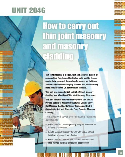
UNIT <strong>2046</strong><br />
How to carry out<br />
thin joint masonry<br />
and masonry<br />
cladding<br />
This unit will cover the following learning<br />
outcomes:<br />
159
<strong>Unit</strong> <strong>2046</strong><br />
How to carry out thin joint masonry and masonry cladding<br />
160<br />
<strong>Level</strong> 2 NVQ/SVQ <strong>Diploma</strong> <strong>Brickwork</strong> 3rd edition<br />
Functional skills<br />
When reading and<br />
understanding the text in<br />
this unit, you are practising<br />
several functional skills:<br />
FE 1.2.1 – Identifying how<br />
the main points and ideas<br />
are organised in different<br />
texts.<br />
FE 1.2.2 – Understanding<br />
different texts in detail.<br />
FE 1.2.3 – Reading different<br />
texts and taking appropriate<br />
action, e.g. respond to<br />
advice/instructions.<br />
If there are any words<br />
or phrases you do not<br />
understand, use a dictionary,<br />
look them up using the<br />
internet or discuss with your<br />
tutor.<br />
Key term<br />
Aircrete – a product name<br />
for blocks manufactured<br />
from autoclaved aerated<br />
concrete<br />
Key term<br />
Swimming effect – this<br />
is where the blocks that<br />
have been laid float on<br />
the wet mortar bed as the<br />
weight upon them increases.<br />
This dramatically affects<br />
the setting time of the<br />
blockwork structure and<br />
restricts the height to which<br />
blocks can be laid in any one<br />
day<br />
K1. Construct buildings using thin joint<br />
blockwork to required specification<br />
Features of the thin joint system<br />
thin joint systems and by representatives of the industry have<br />
concluded that the benefits of the system are invaluable to an<br />
industry where clients, developers and external agencies continue<br />
to demand improved quality of the end product, at the same time<br />
as increased production.<br />
Benefits of the thin joint system<br />
The thin joint method uses a combination of lightweight<br />
Aircrete blocks and a fine sand- and cement-based, quick<br />
drying mortar.<br />
The main benefits of using the thin joint system include:<br />
speed<br />
improved quality of the finished product.<br />
Speed<br />
Blockwork structures can be constructed much more quickly than<br />
traditional methods. This is due to a number of factors.<br />
The quick bonding time of the mortar reduces the swimming<br />
effect caused by the weight of the blockwork on the courses<br />
below.<br />
The accuracy and uniformity of the Aircrete blocks, combined<br />
with the accuracy of the thin joint, reduces the time spent on<br />
levelling individual blocks.<br />
With less mortar being used, the bond strength of the<br />
blockwork is enhanced. This again allows for more stability<br />
during the construction process and also allows other aspects of<br />
the construction work to continue within a short space of time,<br />
after the blockwork structure has been completed.<br />
The thin joint system enables the inner leaf of a cavity wall<br />
structure to be built, in its entirety, prior to the outer leaf<br />
being built. This makes it possible to provide a waterproof<br />
work environment for other trades to carry on with the work<br />
programme.<br />
The availability of larger format blocks also increases the speed<br />
at which walls can be built.
Improved quality of the finished product<br />
<strong>Unit</strong> <strong>2046</strong> How to carry out thin joint masonry and masonry cladding<br />
The quality of the finished product is improved due to a number<br />
of factors.<br />
Aircrete blocks are produced to very accurate sizes, resulting<br />
in the finished product having a cleaner and more uniform<br />
appearance.<br />
As the inner leaf of cavity structures can be built first, it is<br />
easier to maintain a clean cavity and avoid the bridging of wall<br />
ties with mortar.<br />
The thermal insulation properties of the structure are improved<br />
because the mortar joints are thinner and the area of blockwork<br />
is greater. Where larger format blocks are used, even better<br />
thermal insulation is achieved.<br />
Aircrete blocks have high sound insulation properties due to<br />
the material used and the structure of the block.<br />
There is less wastage of materials due to the ease and accuracy<br />
with which the blocks can be cut. Also thin joint mortar is<br />
supplied pre-mixed in 25 kg bags, allowing for just the right<br />
amount to be mixed for the job in hand, as and when required.<br />
Resources required to carry out the thin<br />
joint construction process<br />
Aircrete blocks<br />
These are made from autoclaved aerated concrete. This is a<br />
lightweight material which makes the blocks easy to handle and<br />
to cut, but at the same time has a high compressive strength.<br />
The main ingredients combined to form this material are lime,<br />
sand of quartz, water and cement. As the name suggests, Aircrete<br />
also contains between 60 and 80 per cent of air by volume, with<br />
thousands of tiny air bubbles being produced during the ‘baking’<br />
process. Once this process is complete and the material has been<br />
allowed to set, it is cut into blocks of the required size using<br />
mechanical wires. In order to obtain the maximum strength of<br />
the blocks, they are cured in autoclaves. This is where the<br />
blocks are subjected to saturation with high pressured steam at<br />
temperatures up to 200°C.<br />
Aircrete blocks are available in a variety of sizes ranging from<br />
the standard sized block of 440 mm × 215 mm up to an extra<br />
large block with a face size of approximately 610 mm × 270 mm.<br />
These blocks are also available in varying thicknesses and grades<br />
to suit the work being carried out.<br />
Remember<br />
As there is less mortar used<br />
with the thin joint system,<br />
more blocks will need to be<br />
ordered per metre squared,<br />
when estimating for a<br />
project using a standard<br />
sized block<br />
Did you know?<br />
Data on fire resistance,<br />
‘U’ values and handling<br />
weights of various types<br />
of Aircrete blocks can be<br />
obtained from the various<br />
manufacturers using their<br />
technical helplines<br />
Key term<br />
‘U’ values – these indicate<br />
the thermal performance<br />
of a material in different<br />
situations<br />
Figure 5.1 Aircrete blocks<br />
How to carry out thin joint masonry and masonry cladding <strong>Unit</strong> <strong>2046</strong><br />
161
<strong>Unit</strong> <strong>2046</strong><br />
How to carry out thin joint masonry and masonry cladding<br />
162<br />
<strong>Level</strong> 2 NVQ/SVQ <strong>Diploma</strong> <strong>Brickwork</strong> 3rd edition<br />
Safety tip<br />
It is recommended that<br />
you use suitable hand<br />
protection when using thin<br />
joint mortar. As this type<br />
of mortar is cement-based,<br />
there is a risk of developing<br />
dermatitis and/or burns and<br />
irritation to the skin through<br />
prolonged exposure to it<br />
Did you know?<br />
Always clean the mixer<br />
thoroughly after use, using<br />
either water or ballast and<br />
gravel to prevent future<br />
material from sticking to the<br />
drum sides so easily<br />
Did you know?<br />
Although occasional stirring<br />
or remixing of the thin<br />
joint mortar can be carried<br />
out following the initial<br />
mix, no additional water<br />
should be added as this will<br />
significantly weaken the<br />
bonding properties of the<br />
mix<br />
Thin joint mortar<br />
Mortar is covered in greater detail on pages 199–200. It is formed<br />
from a number of resources:<br />
sand<br />
cement<br />
water<br />
plasticisers (for brickwork)<br />
colouring agents (where coloured mortar is desired).<br />
It usually requires mixing, either by hand or machine, although<br />
certain mortar products can be purchased pre-mixed and ready<br />
for use.<br />
Thin joint mortar is a combination of fine ground sand (silica)<br />
and Portland cements. It is available under a number of different<br />
trade names and is produced by various manufacturers as part of<br />
their thin joint systems. It is normally supplied in 25 kg bags and<br />
then added to water and mixed until the correct consistency is<br />
obtained. Guidance for mixing is given on the packaging.<br />
Thin joint mortar remains workable for a number of hours –<br />
up to four hours in most instances – while still in the bucket.<br />
However, once spread on the block, the mortar will begin to set<br />
within 10 to 20 minutes. Full setting of the mortar is reached after<br />
approximately 1 to 2 hours, depending on the product. Thin joint<br />
mortar is spread at a thickness of 2–3 mm. The tools used for the<br />
mixing and application of the mortar are explained later in this<br />
unit (see pages 164–165).<br />
Machine mixing<br />
Mixing by machine can be carried out by using an electric, petrol<br />
or diesel mixer. Always set the mixer on level ground.<br />
Fill the mixer with approximately half of the water recommended,<br />
adding the plasticiser if it is being used. Add half of the cement<br />
and half of the sand required to the water. Allow them to mix<br />
and then add the remaining cement, then the sand. Add more<br />
water if required, allowing at least two minutes for the mix<br />
to become workable and to ensure that all the materials are<br />
thoroughly mixed together.<br />
Once the mix has been taken out of the mixer, part fill the mixer<br />
with water and allow the water to run for a couple of minutes to<br />
remove any mortar stuck to the sides.
Wall ties for thin joint systems<br />
<strong>Unit</strong> <strong>2046</strong> How to carry out thin joint masonry and masonry cladding<br />
Wall ties used in traditional brick and block structures are not<br />
suitable for use in thin joint systems as they are too thick to<br />
fit into the thin mortar joints. However, there are a variety of<br />
ties compatible with thin joints currently on the market. The<br />
majority of them are made from stainless steel. Some of the most<br />
common include:<br />
twist ties<br />
flat steel ties<br />
abutment wall ties<br />
movement joint ties.<br />
Twist ties<br />
These are used for cavity walls where the<br />
inner leaf has been built and the outer leaf is<br />
still under construction. They are driven into<br />
the Aircrete block work at a height to suit the<br />
outer leaf courses as they are laid. These ties<br />
will also take insulation clips, which secure<br />
partial fill cavity insulation batts. Twist ties<br />
are available in various sizes to suit up to<br />
150 mm cavities.<br />
Flat steel ties<br />
These are available for use when joining the inner and outer leaves<br />
of a cavity wall where the two leaves which are constructed at the<br />
same time and are of the same course height. The ties are bedded<br />
into the blockwork in the same way as traditional methods.<br />
Flat steel ties are also available for connecting blockwork at<br />
junctions, where perimeter walls join partition or dividing walls.<br />
Abutment wall ties<br />
These are also used for connecting blockwork at junctions where<br />
courses are not at the same level. The tie is fixed to the perimeter<br />
wall using a suitable fixing and the other end of the tie sits into<br />
the bed joint of the adjoining wall.<br />
Figure 5.4 Flat steel ties<br />
Figure 5.2 Twist tie<br />
Figure 5.5 Abutment wall tie<br />
Remember<br />
In Scotland, wall ties are also<br />
known as kit ties<br />
Figure 5.3 Insulation clips/discs<br />
How to carry out thin joint masonry and masonry cladding <strong>Unit</strong> <strong>2046</strong><br />
163
<strong>Unit</strong> <strong>2046</strong><br />
How to carry out thin joint masonry and masonry cladding<br />
164<br />
<strong>Level</strong> 2 NVQ/SVQ <strong>Diploma</strong> <strong>Brickwork</strong> 3rd edition<br />
Find out<br />
Find out if there are any<br />
variations to the ties<br />
mentioned that are also<br />
suited to the thin joint<br />
system<br />
Remember<br />
On large sites, or in<br />
instances where a large<br />
number of cuts are required<br />
for the job, a mechanical<br />
hand saw or circular saw<br />
may be used to cut blocks<br />
Figure 5.8 Sledge<br />
Movement joint ties<br />
As the name suggests, these are<br />
used to tie walls together where<br />
the continuous length has been<br />
broken up to allow for movement<br />
joints. They allow for contraction Figure 5.6 Movement tie<br />
and expansion between the two walls to avoid any damage to the<br />
blockwork caused by movement.<br />
Tools and equipment used for the thin joint system<br />
Scoop<br />
This is used to spread thin joint<br />
mortar, producing a consistent joint<br />
thickness of 2–3 mm. The scoop is<br />
available in varying sizes of between<br />
75 and 200 mm.<br />
Figure 5.7 Scoops<br />
Sledge<br />
As with the scoop, this tool is also used to spread thin joint<br />
mortar. However, the sledge is for use where the width of the<br />
block exceeds 200 mm. This tool is available in sizes between 200<br />
and 300 mm.<br />
Masonry hand saw<br />
This is used to cut Aircrete blocks to<br />
the required size.<br />
Block cutting square<br />
This is used as a marking guide<br />
when cutting blocks.<br />
Figure 5.9 Masonry hand saw<br />
Figure 5.10 Block cutting square<br />
Sanding board<br />
The sanding board is used to remove any imperfections in the<br />
bed course. As the thin joint system requires a very accurate bed<br />
thickness to be maintained, it is important that any raised areas in<br />
the bed course are removed prior to applying the thin mortar joint.<br />
Block rasp<br />
The block rasp is used to trim any<br />
areas of the block that are raised<br />
and too big to be removed with a<br />
sanding board. These raised areas<br />
may occur when there has been<br />
inaccurate cutting and will affect the<br />
Figure 5.11 Sanding board accuracy of the thin joint thickness. Figure 5.12 Block rasp
Whisk attachment<br />
<strong>Unit</strong> <strong>2046</strong> How to carry out thin joint masonry and masonry cladding<br />
The whisk is attached to a powered drill and is used to mix the<br />
thin joint mortar in a large tub or bucket.<br />
Bonding for blockwork<br />
Blockwork should be set out to use as many full blocks as<br />
possible. At an internal corner, a 100 mm section of block should<br />
be used to gain half bond. Never use brick on an internal corner,<br />
as the thermal value of a brick is not to the same as a block and<br />
will cause a ‘cold spot’ to the finished area, possibly showing<br />
through the plaster on completion.<br />
Damp proof barriers<br />
The techniques used for this are the same as for cavity walls. This<br />
will be covered on page 269 in <strong>Unit</strong> 2048.<br />
Working with materials<br />
Positioning materials<br />
Before beginning construction work, you will need to position and<br />
stack the components you need to work with on the construction site.<br />
Each site will have different rules for arranging materials, either<br />
placing them nearby or keeping them in a holding compound<br />
until needed. There may be written instructions for storing and<br />
placing materials, or you may be given verbal instructions by a site<br />
manager. In both cases, it is important to check any information<br />
you find confusing and to confirm that you have understood how<br />
materials are to be placed.<br />
Decisions on material placement affect everyone on site, as<br />
everyone needs to know how to access them. Placing materials in<br />
the wrong place could also lead to health and safety issues.<br />
Figure 5.14 Internal block corner<br />
Figure 5.13 Whisk attachment<br />
Remember<br />
Because of the cost of<br />
bricks, most walls above<br />
215 mm thick usually<br />
incorporate blocks as they<br />
are more cost-effective and<br />
have the strength required<br />
How to carry out thin joint masonry and masonry cladding <strong>Unit</strong> <strong>2046</strong><br />
165
<strong>Unit</strong> <strong>2046</strong><br />
How to carry out thin joint masonry and masonry cladding<br />
166<br />
<strong>Level</strong> 2 NVQ/SVQ <strong>Diploma</strong> <strong>Brickwork</strong> 3rd edition<br />
Safety tip<br />
Guidance on the dangers<br />
of working at height can be<br />
found on pages 27–33<br />
Safety tip<br />
As well as your normal PPE,<br />
always wear goggles, gloves<br />
and a face mask when<br />
cutting blocks<br />
Health and safety and risk assessments<br />
One of the main health and safety issues is the risk of mortar<br />
coming into contact with the skin or splashing into the eyes when<br />
it is being used. There is also a risk of inhaling dust or fumes from<br />
mortar. Appropriate PPE (personal protective equipment) such as<br />
gloves, safety goggles and a respiratory mask should be worn.<br />
Blocks should be unloaded and transported around the site by<br />
forklift. If being used on scaffolding, they should also be lifted by<br />
forklift, not carried up ladders by hand or on a shoulder.<br />
Blockwork should not be built too high without proper security<br />
being in place as this may cause structural collapse. This is<br />
particularly important if working in windy conditions as walls can<br />
be blown down, causing damage to property or people. Another<br />
reason to avoid laying too high is that you will not be able to see<br />
the line correctly. If the block touches the line, it will move and<br />
cause the wall to bow. You could also cause yourself damage by<br />
reaching too high, pulling muscles in your back or stomach.<br />
Wall ties must not be left exposed, as there is the danger that<br />
workers and site users may snag themselves on the ties.<br />
You must conduct a risk assessment of the area you are working<br />
in to identify any site-specific risks that may exist. You will then<br />
be able to put work practices into effect to protect you from<br />
the risks.<br />
Cutting components<br />
When preparing to build walls, you may need to cut and prepare<br />
blocks. There are three different methods that can be used:<br />
by hand using a hammer and bolster chisel<br />
by hand using a saw<br />
by machine using a portable disc cutter or fixed table saw.<br />
The method used sometimes depends on the type of block being<br />
used. For example:<br />
A hand saw would be no good to cut concrete blocks, but<br />
perfect for lightweight blocks.<br />
A hammer and bolster are adequate for concrete blocks, but<br />
can chip the edges of the cut. If the cut blocks are to be covered<br />
by another material, this would be acceptable, but if the blocks<br />
have a face finish, then machine cutting would be the better<br />
option, especially if a large number of cuts are required.
<strong>Unit</strong> <strong>2046</strong> How to carry out thin joint masonry and masonry cladding<br />
Protecting materials and completed work<br />
After completing a day’s work, the bricklayer must take<br />
precautions to prevent damage to the wall from the weather.<br />
Rain will cause mortar joints to run over the face of the wall,<br />
causing unsightly stains. To prevent rain damage, walls should<br />
be covered with a polythene sheet or tarpaulin. A scaffold board<br />
or bricks can be used to secure the cover in place. The sheeting<br />
should be kept clear of the wall to allow for ventilation.<br />
Cold weather could cause the water in the mortar to freeze,<br />
damaging the bonds between blocks and bricks, making the wall<br />
weak and possibly causing the wall to be taken down. To prevent<br />
the mortar from freezing, newly built walls should be covered if<br />
there is a sudden drop in temperature to below 3ºC. The covering<br />
should consist of a layer of hessian or insulation slabs, with a<br />
waterproof tarpaulin or plastic sheeting on top.<br />
Maintaining industrial standards<br />
Industrial standards are the standards and tolerances allowed on<br />
site, or in the workshop, covering the plumbness, level and finish<br />
of a wall, if it is to gauge, if the joints on courses run true and<br />
plumb, as well as the cleanliness of the wall once built.<br />
Figure 5.15 Protecting newly laid brickwork<br />
Key term<br />
Gauge – the blockwork<br />
course heights; for a block<br />
size of 215 mm, this would<br />
be the size plus the 10 mm<br />
joint – 225 mm; gauge can<br />
be maintained by using a<br />
gauge rod<br />
Figure 5.16 Gauge rod in use<br />
How to carry out thin joint masonry and masonry cladding <strong>Unit</strong> <strong>2046</strong><br />
167
<strong>Unit</strong> <strong>2046</strong><br />
How to carry out thin joint masonry and masonry cladding<br />
168<br />
<strong>Level</strong> 2 NVQ/SVQ <strong>Diploma</strong> <strong>Brickwork</strong> 3rd edition<br />
Remember Forms of construction where the thin joint<br />
system can be used<br />
The standard block size is<br />
440 mm x 215 mm<br />
Safety tip<br />
Always remember the basics<br />
of kinetic lifting techniques<br />
when handling blocks,<br />
particularly the larger size<br />
blocks available with the<br />
thin joint system<br />
Remember<br />
It is essential that the bed<br />
course is level and free from<br />
imperfections prior to laying<br />
the first bed of the thin joint<br />
mortar<br />
Remember<br />
You must always ensure that<br />
the course that is to receive<br />
a bed of thin joint mortar<br />
is free from dust as this can<br />
adversely affect the adhesion<br />
of the mortar<br />
Key term<br />
Superstructure – work<br />
above the DPC<br />
Figure 5.17 A bed course of<br />
blocks laid with traditional<br />
mortar bed and with thin joint<br />
mortar vertical joints<br />
The structure and composition of Aircrete blocks make them a<br />
very versatile material. When they are used in conjunction with<br />
the thin joint mortars that are now available, the thin joint system<br />
becomes suitable for most aspects of construction normally<br />
associated with the more traditional types of materials. The thin<br />
joint system can be used for any of the following:<br />
foundations<br />
partition walling<br />
external solid walling<br />
cavity walling<br />
separating or party walls.<br />
As the thin joint system has high resistance to both water<br />
penetration and frost, few problems are encountered when it is<br />
used for external solid walling. However, it is recommended that<br />
the external face of the blockwork is finished with either cladding<br />
or a traditional rendered finish, particularly where the wall is<br />
constantly exposed to inclement weather, such as rain and frost.<br />
The thin joint system also has a high resistance to fire and good<br />
sound insulation qualities, making it highly suitable for the<br />
construction of partition walling and separating walls.<br />
The strength and sulphate resistant properties of the system,<br />
also make it suitable for foundation walls in most types of soil and<br />
ground conditions.<br />
Methods of construction using the thin<br />
joint system<br />
If constructing a cavity wall structure, it is important to ensure<br />
that the substructure walls are built up to the damp proof course<br />
(DPC) prior to laying the inner thin joint blockwork. This enables<br />
any required openings to be set out accurately before work starts<br />
on the superstructure.<br />
2–3 2–3 mm mm thin joint thin mortar joint – mortar –<br />
vertical joints joints in order in to order to<br />
maintain bonding accuracy<br />
for maintain the next course bonding of blocks accuracy<br />
for the next course of blocks<br />
10 mm bed joint laid with<br />
traditional mortar to enable any<br />
inaccuracies 10 mm bed joint in the la concrete to be<br />
traditional mortar<br />
taken inaccuracies out and in to theproduce<br />
a level<br />
bed taken for the out and thin to joint p system<br />
bed for the thin jo
<strong>Unit</strong> <strong>2046</strong> How to carry out thin joint masonry and masonry cladding<br />
In most cases the first course or ‘bed course’ in the thin joint<br />
system should be laid using the normal sand/cement mortar. This<br />
will take out any inaccuracies that are present within the floor slab<br />
or foundation masonry.<br />
In order to maintain accuracy in the courses above the bed<br />
course, thin joint mortar may be used for the perps (vertical<br />
joints) of the bed course. Once the bed course is sufficiently<br />
stable, work with the thin joint system can commence.<br />
Bonding arrangements and the installation methods are much the<br />
same as the traditional block laying methods.<br />
When erecting the corners of block walls built using the thin<br />
joint system, it is vitally important to ensure accuracy in the<br />
levelling, plumbing and gauging of the blocks. With the thin joint<br />
system there is no option of opening up joints to compensate for<br />
inaccuracies you might have caused during the build.<br />
Once the corners have been erected, the blocks can be run<br />
into a line as normal. The thin joint mortar is applied to the<br />
blocks using a scoop or a sledge depending on the width of the<br />
block (see the descriptions of these tools on page 164). Both tools<br />
provide a consistent 2–3 mm layer of mortar across the bed and<br />
vertical joints.<br />
As the individual blocks are laid, they should be firmly pushed<br />
against the vertical, mortared face of the previously laid block<br />
and at the same time lowered onto the mortared bed below. It<br />
is important to ensure that full joints are maintained at all times<br />
to retain the effectiveness and stability of the thin joint system.<br />
Where there is a need to tap blocks into place to ensure full<br />
uniform joints that are accurately laid to the line, a rubber mallet<br />
should be used in order to prevent damage to the blocks.<br />
As previously stated, when constructing cavity walls, the inner leaf<br />
can be built in its entirety prior to work commencing on the outer<br />
leaf. This has a number of advantages:<br />
a watertight structure is provided at a much earlier stage of<br />
the project<br />
partial or full fill insulation can be fitted much more easily and<br />
will not be affected by excess mortar protruding from joints<br />
wall ties can be fixed once the insulation is in place – the<br />
insulation is then secured by the wall tie being driven into<br />
the pre-erected blockwork and secured with suitable<br />
insulation clips<br />
it is easier to keep a clean cavity as the outer leaf is constructed.<br />
Key term<br />
Perps – the vertical joints<br />
between two bricks or<br />
blocks<br />
Did you know?<br />
Bond arrangements for the<br />
thin joint system are the<br />
same as those used in the<br />
traditional brick and block<br />
methods<br />
Did you know?<br />
Where a single skin of<br />
walling is built in its entirety<br />
and is not supported by<br />
other walls, it should be<br />
supported or propped up<br />
until the mortar has fully set<br />
and is sufficiently stable. If<br />
this is not done, particularly<br />
during adverse weather<br />
conditions, the wall may<br />
collapse<br />
Did you know?<br />
Where wall ties are to<br />
be driven into the newly<br />
constructed inner leaf,<br />
it is recommended that<br />
the blockwork has been<br />
stabilised by the installation<br />
of the floor joists at the<br />
head of the wall<br />
Remember<br />
The spacing of wall ties<br />
is the same as when<br />
constructing cavity walling<br />
with traditional methods<br />
How to carry out thin joint masonry and masonry cladding <strong>Unit</strong> <strong>2046</strong><br />
169
<strong>Unit</strong> <strong>2046</strong><br />
How to carry out thin joint masonry and masonry cladding<br />
170<br />
<strong>Level</strong> 2 NVQ/SVQ <strong>Diploma</strong> <strong>Brickwork</strong> 3rd edition<br />
Find out<br />
Are there any other<br />
materials from which<br />
reinforcement for thin joint<br />
systems can be made?<br />
Functional skills<br />
Working with arches in<br />
buildings will allow you to<br />
use a range of functional<br />
skills, including FM 1.2.1b:<br />
Interpreting information<br />
from sources such as<br />
diagrams, tables, charts<br />
and graphs and FM 1.2.1d:<br />
Calculate perimeters and<br />
areas of simple 2D and 3D<br />
objects.<br />
Forming openings in walling<br />
There are many types of opening in cavity walling. Openings for<br />
doors and windows are covered on page 244 of <strong>Unit</strong> 2048.<br />
Reveals<br />
Reveals are formed in much the same way as with traditional<br />
construction methods. The Aircrete blocks can be cut to the<br />
required dimensions of the reveal, however the first reveal block may<br />
require support to enable the remaining blocks to be laid on top.<br />
Arches<br />
Arches have been used for many centuries in very different<br />
types of construction including bridges, viaducts, aqueducts,<br />
castles, as well as the simplest and most modern forms of<br />
housing structures.<br />
The curved shape of an arch allows the weight of the masonry<br />
above it (the load) to be distributed evenly down through the walls<br />
at each side. The arch is not exposed to tensile stresses (forces that<br />
pull apart), because it is wedged between the walls on each side,<br />
and therefore will not collapse when a load is placed above it.<br />
There are certain terms used when referring to parts of an arch,<br />
particularly during its construction, all of which you will come<br />
across in this unit. Figure 5.18 shows many of the different parts<br />
of an arch and Table 5.1 describes what these are.<br />
Figure 5.18 The parts of an arch<br />
G<br />
J<br />
D<br />
H<br />
A<br />
C<br />
K<br />
B<br />
E<br />
L F<br />
I
Letter Part Letter Part<br />
A Span – the distance<br />
between the abutments<br />
that support the arch<br />
B Springing line – the<br />
line at which the arch<br />
sits on the abutments<br />
C Rise – the height of the<br />
arch from the springing<br />
line to the soffit<br />
D Intrados – the interior<br />
lower line or curve of the<br />
arch ring<br />
E Extrados – the outside<br />
line of the arch ring<br />
F Springing point – the<br />
point at which the arch<br />
meets the abutments<br />
Table 5.1 Arch construction terminology<br />
<strong>Unit</strong> <strong>2046</strong> How to carry out thin joint masonry and masonry cladding<br />
G Springer – the first brick<br />
of the arch seated on<br />
the springing line<br />
H Key (or key brick) – the<br />
central brick or stone at<br />
the top of an arch<br />
I Skewback – the angle<br />
at the springing point,<br />
on the abutments, at<br />
which the arch ring<br />
bricks will be laid<br />
J Collar joint – the<br />
horizontal or bed joint<br />
separating the arch rings<br />
K Crown – the very top<br />
point of the extrados<br />
L Soffit – the underside<br />
face of the arch<br />
Some other important arch construction terminology includes:<br />
Haunch – the bottom part of the arch ring from the springing<br />
point to half-way up the ring.<br />
Radius – the distance from the central point on the springing<br />
line (known as the striking point) to the intrados.<br />
Striking point – the central point of the springing line from<br />
which the arch radius is struck.<br />
Voussoirs – the wedge-shaped bricks/stones of which the arch<br />
is made.<br />
Key term<br />
Abutments – the walls or<br />
structures through which<br />
the weight above the arch<br />
is distributed, as well as<br />
the walls or structures<br />
supporting the ends of the<br />
arch<br />
How to carry out thin joint masonry and masonry cladding <strong>Unit</strong> <strong>2046</strong><br />
171
<strong>Unit</strong> <strong>2046</strong><br />
How to carry out thin joint masonry and masonry cladding<br />
172<br />
<strong>Level</strong> 2 NVQ/SVQ <strong>Diploma</strong> <strong>Brickwork</strong> 3rd edition<br />
Did you know?<br />
A segmental arch is also<br />
known as a soldier arch.<br />
This is because the bricks are<br />
standing on their end in the<br />
arch – they are standing ‘to<br />
attention’!<br />
Did you know?<br />
The methods used to bridge<br />
openings for arches are<br />
the same as those used<br />
to prevent damp from<br />
penetrating cavity walling.<br />
Cavity trays are not made to<br />
match shaped lintels, such<br />
as the curved lintel for an<br />
arch, so a gap will occur<br />
between the lintel and the<br />
cavity tray. This needs to be<br />
taken into consideration<br />
Remember<br />
Openings are the only<br />
points where moisture can<br />
penetrate. However, the<br />
use of a cavity tray over an<br />
opening drains any moisture<br />
that does settle out of<br />
the wall, preventing the<br />
moisture from penetrating<br />
and bridging the cavity<br />
Methods of constructing simple arches<br />
Two of the most common shapes of arch are the segmental<br />
(Figure 5.19) and semi-circular (Figure 5.20). Both shapes can<br />
be constructed by using either the rough ringed arch or axed arch<br />
methods.<br />
Figure 5.19 An example of a segmental arch<br />
Figure 5.20 An example of a semi-circular arch
Rough ringed arch method<br />
<strong>Unit</strong> <strong>2046</strong> How to carry out thin joint masonry and masonry cladding<br />
This method involves using wedge-shaped joints with standard<br />
sized bricks to form the arch ring. The size of the joints is<br />
determined by the arch centre or turning piece. The bricks<br />
used in the arch ring are normally laid as headers as opposed to<br />
stretchers (see Figure 5.21). If stretchers were used, the joints<br />
would need to be much wider to ensure that the desired shape<br />
was obtained and this could result in an unsightly appearance.<br />
The overall height of the arch is reached by using a number of<br />
arch rings.<br />
Assuming that the turning piece, or arch centre, has been<br />
correctly positioned and adequately supported with props, and<br />
that the folding wedges are in place, the method of construction<br />
is as follows.<br />
Identify the striking point on the timber turning piece or arch<br />
centre and plumb a vertical line up from this point to the top of<br />
the support. This will give you the centre point of the key brick’s<br />
position. Mark the width of the key brick on the arch centre or<br />
turning piece. Then on either side of the key brick proceed to<br />
mark out, down the length of the intrados, equal brick spacings.<br />
Figure 5.21 Headers used to form an arch ring<br />
Headers<br />
Key term<br />
Arch centre – the<br />
temporary timber support<br />
for the arch ring on semicircular<br />
arches during<br />
construction<br />
Turning piece – the<br />
temporary timber support<br />
for the arch ring on<br />
segmental arches during<br />
construction<br />
Folding wedges – pieces<br />
of timber cut from 1 mm at<br />
one end to approximately 50<br />
mm at the other to form a<br />
wedge shape<br />
How to carry out thin joint masonry and masonry cladding <strong>Unit</strong> <strong>2046</strong><br />
173
<strong>Unit</strong> <strong>2046</strong><br />
How to carry out thin joint masonry and masonry cladding<br />
174<br />
<strong>Level</strong> 2 NVQ/SVQ <strong>Diploma</strong> <strong>Brickwork</strong> 3rd edition<br />
Figure 5.22 The striking point<br />
Figure 5.23 Placing bricks<br />
Evenly spaced<br />
brick markings<br />
Work alternately<br />
from each side<br />
Line plumbed up<br />
to establish key<br />
brick centre point
<strong>Unit</strong> <strong>2046</strong> How to carry out thin joint masonry and masonry cladding<br />
Note that these spacings must include allowance for mortar<br />
joints. The size of the joints may need to be altered slightly during<br />
bedding to allow for any deviation of brick size or to enable equal<br />
brick spacing around the timber support. Normally the joint size is<br />
slightly reduced from that of the standard 10 mm mortar joint in<br />
order to compensate for the widening of the joint at the extrados.<br />
Commence with the placement of the bricks forming the arch<br />
ring, with the first brick being laid against the skewback angles on<br />
either side of the key brick.<br />
It is important to ensure that there is no bedding between<br />
the brick and the timber centre, as this will result in difficulty<br />
in maintaining the correct curve of the arch bricks during<br />
construction and also stain the face of the bricks exposed once the<br />
support is removed. Packing may be introduced at the base of the<br />
Line pins<br />
Figure 5.24 Dead men in use<br />
Dead men<br />
Line<br />
Line pins<br />
How to carry out thin joint masonry and masonry cladding <strong>Unit</strong> <strong>2046</strong><br />
175
<strong>Unit</strong> <strong>2046</strong><br />
How to carry out thin joint masonry and masonry cladding<br />
176<br />
<strong>Level</strong> 2 NVQ/SVQ <strong>Diploma</strong> <strong>Brickwork</strong> 3rd edition<br />
Remember<br />
Arch supports must not be<br />
removed until the bedding<br />
mortar has fully hardened<br />
Functional skills<br />
When faced with a problem<br />
on site, such as this problem<br />
with arch construction, you<br />
will have the opportunity<br />
to practise the interpreting<br />
elements of functional skills.<br />
This includes FM 1.3.1:<br />
Judge whether findings<br />
answer the original problem;<br />
FM 1.3.2: Communicate<br />
solutions to answer practical<br />
problems.<br />
joint being formed to allow for ease of pointing once the support<br />
is removed.<br />
Bricks should be laid alternately on either side of the key brick to<br />
ensure that there is no overloading on any particular side of the<br />
support. Once the key brick position has been reached you must<br />
ensure that this brick is placed accurately in the marked position on<br />
the centre and that there are fully compacted joints either side of it.<br />
Throughout the construction of the arch rings you must also<br />
maintain the face plane of the brickwork. This can be done by<br />
using a suitable, accurate straight edge or by erecting temporary<br />
line supports on each of the abutments. These can be built in<br />
brick and are known as dead men (see Figure 5.24) or can consist<br />
of timber or metal profiles, accurately gauged and plumbed.<br />
Axed arch method<br />
This method is the total reverse to that of the rough ringed arch.<br />
In this method it is the bricks themselves that are cut to a wedge<br />
shape and the joints are uniform in shape and do not taper. The<br />
wedge-shaped bricks are referred to as voussoirs.<br />
Working life<br />
Max is setting out a semi-circular arch to form an archway to a garden wall.<br />
He has set the arch centre in place and is marking out the brick positions on<br />
the arch centre using a gauge of 75 mm. However, that creates a 15 mm gap<br />
to place a brick into.<br />
How can Max get over this to make the arch correct? He will need to<br />
consider all the parts of the construction process. What might he need to do<br />
if the gap was larger?<br />
Shaped bricks<br />
Key brick central<br />
Figure 5.25 Section of an axed arch with shaped bricks
<strong>Unit</strong> <strong>2046</strong> How to carry out thin joint masonry and masonry cladding<br />
Insulation requirements for walling<br />
therefore save energy. The Building Regulations tell us how much<br />
insulation is required in various situations and in most cases this<br />
would be set out in the specification in order for the relevant<br />
project to obtain planning permission from the local council.<br />
There are three main ways to insulate the cavity:<br />
total or full fill<br />
partial fill<br />
injection (after construction).<br />
Total or full fill<br />
Figure 5.26 shows a section of a total fill cavity wall. The cavity is<br />
completely filled with insulation batts as the work proceeds. The<br />
batts are 450 mm × 1200 mm, made of mineral fibres and placed<br />
between the horizontal wall ties.<br />
Partial fill<br />
Figure 5.27 shows a partial fill cavity wall, where the cavity<br />
insulation batts are positioned against the inner leaf and held in<br />
place by plastic clips. More wall ties than usual are used to secure<br />
the insulation in place.<br />
Injection<br />
This is where the insulation is injected into the cavity after<br />
the main structure of the building is complete. The two main<br />
materials used are Rockwool fibreglass or polystyrene granules.<br />
On a new build, holes are drilled into the inner walls at about<br />
1 m centres and the insulation is pumped into the cavity. If<br />
an older property were injected, then the holes would be<br />
drilled into the external mortar joints. The holes are then filled<br />
with mortar.<br />
There are three key points regarding insulating cavity walls:<br />
handle and store insulation material carefully to avoid damage<br />
or puncturing<br />
the cavities should be clean<br />
read the drawing specifications and follow the manufacturers’<br />
instructions carefully.<br />
Figure 5.26 Wall with total or<br />
full fill<br />
Figure 5.27 Wall with partial fill<br />
Remember<br />
When injecting insulation,<br />
great care must be taken<br />
not to drill the bricks as they<br />
will be difficult and costly to<br />
replace<br />
How to carry out thin joint masonry and masonry cladding <strong>Unit</strong> <strong>2046</strong><br />
177
<strong>Unit</strong> <strong>2046</strong><br />
How to carry out thin joint masonry and masonry cladding<br />
178<br />
<strong>Level</strong> 2 NVQ/SVQ <strong>Diploma</strong> <strong>Brickwork</strong> 3rd edition<br />
Figure 5.28 Wall being injected<br />
Remember<br />
Always check the<br />
specifications to determine<br />
the type and size of<br />
reinforcement required<br />
Key term<br />
Subsidence – the sinking<br />
in of buildings, etc.<br />
Did you know?<br />
Separating walls are also<br />
known as party walls<br />
Figure 5.29 Reinforcement<br />
materials available for use in thin<br />
joint systems<br />
Using reinforcement in<br />
walling<br />
<strong>Brickwork</strong> is extremely strong in<br />
compression (being squashed), but weak<br />
in tension (being stretched). If there is any<br />
chance of brickwork being subjected to<br />
tensile forces (being stretched) some kind<br />
of reinforcement should be built into<br />
the wall.<br />
Reinforcing can be done in several ways,<br />
but the most common way is to build in<br />
a steel mesh called expanding metal. The<br />
mesh is built into the bed joints. Various<br />
widths can be obtained for different thicknesses of wall.<br />
<strong>Brickwork</strong> can also be reinforced vertically with steel rods<br />
and concrete.<br />
Some places where reinforced brickwork could be used are:<br />
over large span door or window openings<br />
where high security is required (such as a bank vault)<br />
in gate pillars<br />
in foundations where there is a possibility of subsidence<br />
in concrete columns.<br />
Reinforcement for thin joint blockwork<br />
Where thin joint blockwork is likely to be subjected to tensile<br />
forces, reinforcement can be built into the horizontal bed of the<br />
thin joint walling. However, only reinforcement material specially<br />
designed for use with the thin joint system should be used. Thin<br />
joint reinforcement is widely available and made from either<br />
stainless steel wire or galvanised steel with a zinc coating. It is<br />
supplied in rolls of up to 50 m in length and is approximately<br />
1.2 mm thick.<br />
Thin joint reinforcement must be bedded within the thin joint<br />
mortar. Where there is a need to overlap the reinforcement,<br />
the overlap should be a minimum of 225 mm. Where the<br />
reinforcement is used around openings, it should extend by at<br />
least 600 mm into the blockwork on both sides of the opening.<br />
Reinforcement can also be used in lengths of thin joint blockwork<br />
over 6 m as an alternative to using movement joints. This is<br />
particularly effective for separating walls where movement joints<br />
cannot be used.
Figure 5.30 Vertical movement joint<br />
Using vertical movement joints<br />
<strong>Unit</strong> <strong>2046</strong> How to carry out thin joint masonry and masonry cladding<br />
Architects and designers have found through experience that<br />
walls that are very long (10 m plus) can crack due to movement<br />
caused by:<br />
temperature change<br />
wetting and drying of the wall.<br />
Movement joint (mastic seal over polythene-type foam filler)<br />
To solve the problem of movement, a wall can be divided into<br />
shorter lengths by introducing movement joints, which are<br />
actually an intended ‘straight’ joint filled with compressible<br />
(squashable) filler. This is then covered with mastic to seal the<br />
joint, preventing water penetration, but allowing movement.<br />
Where the design of the structure requires the use of movement<br />
joints, manufacturers of Aircrete blocks recommend the following:<br />
the first movement joint should be no more than 3 m from the<br />
corner of a fixed end<br />
long lengths of walling should be made up of separate panels<br />
no longer than 6 m.<br />
Movement joints can be formed either by introducing 10 mm<br />
gaps between the panels and filling with fibre boards, or by using<br />
specially designed ties to connect the two panels together, but<br />
allow movement of any panel that is subjected to tensile stress.<br />
These specially designed ties are also available for use when tying<br />
walls together at junctions, for example where partition walls meet<br />
with perimeter walls and particularly those junctions that are<br />
susceptible to movement.<br />
Find out<br />
What is the maximum<br />
vertical distance between<br />
ties when used in a<br />
movement joint?<br />
Figure 5.31 The use of<br />
movement ties<br />
How to carry out thin joint masonry and masonry cladding <strong>Unit</strong> <strong>2046</strong><br />
179
<strong>Unit</strong> <strong>2046</strong><br />
How to carry out thin joint masonry and masonry cladding<br />
180<br />
<strong>Level</strong> 2 NVQ/SVQ <strong>Diploma</strong> <strong>Brickwork</strong> 3rd edition<br />
Figure 5.32 An example of<br />
pre-cast cladding panels<br />
K2., K3. Construct masonry for use with<br />
timber-, concrete- and steel-framed<br />
buildings to required specification<br />
structures into modern construction projects, cladding has<br />
become the ideal way of transforming these potentially drab<br />
and dreary buildings into structures that fully complement the<br />
aesthetic requirements of the environment in which they are built.<br />
The skills for the use of masonry with these different building<br />
frames are the same, so we will look at these topics together:<br />
how to construct masonry for use with timber-framed buildings<br />
how to construct masonry for use with concrete- and steelframed<br />
structures.<br />
Types of cladding other than masonry<br />
cladding<br />
There are a number of materials other than brick and block<br />
that can be used to clad a structure. The most common types of<br />
cladding used in modern construction are described below.<br />
Traditional brick and block cladding<br />
This type of cladding consists of an outer leaf of brick or block<br />
being constructed using the normal materials and methods<br />
associated with building cavity walling. It is tied back to the main<br />
structure using specially designed ties.<br />
However, this type of cladding is restricted to low-rise buildings<br />
of no more than two or three storeys. This is because walls<br />
constructed in this way are incapable of adequately supporting<br />
their own weight above a certain height. The use of this type<br />
of cladding for taller buildings would also increase the risk of<br />
movement due to shrinkage of the main structural components,<br />
stress to the structure caused through wind pressures, settlement<br />
within the main structure, etc.<br />
Pre-cast brick panels<br />
These units are pre-cast and manufactured in production plants<br />
away from the construction site where they are to be used. They<br />
are usually much thinner in section than traditional brick outer<br />
leaves and are not designed to carry any structural loads.<br />
Numerous pre-cast cladding systems of this type are available and<br />
each is fixed in its own special way, usually to the main structure
<strong>Unit</strong> <strong>2046</strong> How to carry out thin joint masonry and masonry cladding<br />
or one panel to another. In many instances, they are fixed in such<br />
a way that there is no need for traditional mortar courses and<br />
jointing methods.<br />
In addition to the pre-cast units above, pre-fabricated brickwork<br />
is increasingly being used in modern construction projects. This<br />
type of brickwork consists of panels of traditional brickwork being<br />
built in a production plant and transported to site where it is lifted<br />
into position. This requires the brickwork to be pre-tensioned<br />
with the use of steel reinforcement so that the whole panel can<br />
be transported from the factory to the site without damaging or<br />
weakening it.<br />
Brick slip and brick tile systems<br />
This type of cladding consists of brick slips, or tiles of<br />
approximately 25–35 mm in thickness, fixed to a pre-fabricated<br />
panel, which is in turn fixed to the main structure.<br />
The slips, or tiles, are fixed either by using a special adhesive or by<br />
mechanical fixing methods. All joint finishing is normally carried<br />
out once the installation is complete. Joint finishing is achieved<br />
by pumping a special cement-based mortar into the vertical and<br />
horizontal joints and then forming a joint finish in the normal way.<br />
Alternative cladding materials<br />
In addition to brick and block claddings, pre-cast panels can<br />
also be produced from materials such as concrete, stone, granite<br />
and slate. Of these, concrete cladding is the most common. It is<br />
normally in the form of pre-cast concrete panels reinforced with<br />
steel mesh and/or rods and available in a wide range of colours<br />
and finishes. The finish of these units can resemble a stone effect,<br />
standard rendered finishes and even a brick facing.<br />
Masonry cladding<br />
Traditional construction methods require the bricklayer to build<br />
outer and inner leaves of brick and blockwork with a gap of 50–75<br />
mm separating them. The two separate leaves are tied together<br />
using galvanised steel ties. This is referred to as cavity wall<br />
construction. In most cases, cavity walls built in the traditional<br />
way are load-bearing. However, the traditional cavity walling<br />
construction is usually restricted to buildings of no more than two<br />
or three storeys in height.<br />
Where buildings are built in excess of three or four storeys, an<br />
outer skin of facing brickwork may be used to cover the main<br />
framed structure. Traditionally, these multi-storey buildings have<br />
Key term<br />
Brick slips – these usually<br />
have the same length<br />
and height dimensions as<br />
standard clay bricks used<br />
in traditional construction<br />
methods. However, the<br />
thickness of the slip is<br />
normally no more than 25<br />
mm. Generally brick slips are<br />
made from exactly the same<br />
material as standard clay<br />
bricks<br />
Did you know?<br />
Some manufacturers of<br />
brick slips and tiles are<br />
now producing this type of<br />
cladding in sizes larger than<br />
the standard brick sizes<br />
Key term<br />
Load-bearing – walls<br />
referred to as load-bearing<br />
support the load from roofs<br />
and floors<br />
Remember<br />
The main purpose or<br />
function of any masonry<br />
cladding is to provide<br />
the decorative finish to a<br />
structure<br />
How to carry out thin joint masonry and masonry cladding <strong>Unit</strong> <strong>2046</strong><br />
181
<strong>Unit</strong> <strong>2046</strong><br />
How to carry out thin joint masonry and masonry cladding<br />
182<br />
<strong>Level</strong> 2 NVQ/SVQ <strong>Diploma</strong> <strong>Brickwork</strong> 3rd edition<br />
Remember<br />
Whatever system you<br />
use, remember the<br />
manufacturer’s installation<br />
instructions must be<br />
followed. Not only will<br />
these guide you on how to<br />
carry out the work, they will<br />
ensure that the cladding<br />
does its job and will not fail<br />
over time<br />
Remember<br />
In Scotland, a cavity barrier<br />
is also known as a firestop<br />
Figure 5.33 Cavity barriers at separating wall positions<br />
been constructed from pre-cast concrete sections slotted together.<br />
The outer skin of brickwork is tied into the main structure using<br />
purpose-made fixings or metal support systems. A cavity still<br />
needs to be formed to ensure that the correct insulation properties<br />
required for the building are achieved. In most instances the outer<br />
skin is not required to carry any load imposed by floors or roofs,<br />
as this is supported by the main framed structure.<br />
Where the brick outer skin is not required to support any load, it<br />
is known as masonry cladding.<br />
Masonry cladding is also used to cover buildings of timberand<br />
steel-framed construction. Timber-frame construction is<br />
becoming increasingly popular in modern house building. The<br />
inner leaf of timber-frame buildings consists of pre-formed panels<br />
made from structural timbers capable of supporting the loads<br />
imposed by the floors and roof. Steel-framed structures are more<br />
commonly used for buildings such as factory and warehouse units.<br />
As with the more traditional multi-storey concrete structures,<br />
the cladding will be tied back to the main structure using metal<br />
support systems.<br />
In whatever situation masonry cladding is used, there are a number<br />
of different methods of installing and fixing the cladding to the<br />
main structure. A wide variety of fixing systems are available.<br />
Health and safety issues<br />
Whichever support system is used when installing cladding, it<br />
is of the utmost importance that the installation procedures are<br />
accurately followed. Failure to follow guidelines may result in failure<br />
of the support system and eventual weakening of the cladding<br />
sections and even collapse.<br />
Preventing fire hazards<br />
Regulations require that for any timber-frame<br />
dwelling, of two storeys or more, cavities must<br />
be closed at specified intervals with the use of<br />
cavity barriers. The spacing and positioning<br />
of these barriers will be identified within the<br />
specifications and drawings.<br />
The following illustrations show examples of<br />
the positioning of cavity barriers in timberframe<br />
construction.
Clout nails or staples<br />
Cavity barrier<br />
Figure 5.34 Cavity barriers at reveals<br />
<strong>Unit</strong> <strong>2046</strong> How to carry out thin joint masonry and masonry cladding<br />
Methods of supporting/fixing cladding<br />
As previously mentioned, there are many new cladding systems<br />
being introduced into construction and each has their own<br />
particular installation procedures and fixing components. It<br />
is impossible to cover them all here, but the following section<br />
Block inner leaf<br />
supported<br />
by floor slab<br />
Reinforced<br />
concrete<br />
floor slab<br />
Concrete edge<br />
beam formed<br />
as part of<br />
floor slab<br />
Inner leaf of<br />
blockwork<br />
DPC<br />
cavity tray<br />
Soldier course is cast<br />
in-situ along with the<br />
floor slab and attached<br />
by purpose made<br />
fixings fixed into the<br />
brick using special resin<br />
Soldier course tied<br />
to concrete edge<br />
beam with purpose<br />
made metal brackets<br />
Compression joint<br />
(explained later<br />
in chapter)<br />
Outer leaf of<br />
brick cladding<br />
Figure 5.36 Typical concrete floor slab incorporating a<br />
reinforced edge beam<br />
Timber frame<br />
Cavity<br />
Clout nails or staples<br />
External brick leaf<br />
Breather<br />
membrane<br />
Figure 5.35 Cavity barriers at intervals within main cavity<br />
Block inner leaf<br />
supported<br />
by toe beam<br />
Reinforced<br />
concrete<br />
floor slab<br />
Concrete toe<br />
beam formed<br />
as part of the<br />
floor slab<br />
Did you know?<br />
Brick slip and brick tile<br />
cladding is mainly used on<br />
steel- or concrete-framed<br />
structures<br />
DPC<br />
cavity tray<br />
Brick to have<br />
bearing on toe<br />
beam of at least<br />
2 /3 of the brick width<br />
Brick slip/tile glued<br />
to the toe beam to<br />
hide concrete face<br />
Compression joint<br />
Brick outer leaf<br />
Figure 5.37 Typical concrete floor slab incorporating a<br />
reinforced toe beam<br />
2 /3<br />
How to carry out thin joint masonry and masonry cladding <strong>Unit</strong> <strong>2046</strong><br />
183
<strong>Unit</strong> <strong>2046</strong><br />
How to carry out thin joint masonry and masonry cladding<br />
184<br />
<strong>Level</strong> 2 NVQ/SVQ <strong>Diploma</strong> <strong>Brickwork</strong> 3rd edition<br />
Figure 5.38 Expansion bolt<br />
for fixing a support beam to a<br />
concrete structure<br />
Plate turned 90°<br />
Figure 5.39 Purpose-made bolts slotting into a<br />
channel fixed to the main concrete structure<br />
Did you know?<br />
joints are referred to as<br />
compression joints<br />
provides an insight into the traditional methods of installing and<br />
fixing different types of cladding and the basic principles behind<br />
more modern methods.<br />
Traditionally, brickwork cladding used on multi-storey concrete<br />
structures is supported at each floor level by specially formed and<br />
reinforced concrete toe or edge beams. These toe or edge beams<br />
are formed as part of the concrete floor slab.<br />
However, with the introduction of metal support systems, the use<br />
of concrete support beams is becoming less common. Continuous<br />
lengths of metal supporting beams can be fixed to the structural<br />
concrete either by purpose-made expansion<br />
bolts or by specially designed bolts that fit into a<br />
channel slotted into or fixed to the surface of the<br />
concrete.<br />
90°<br />
When fixing these types of metal supports to<br />
steel-framed structures, the support beam can be<br />
fixed directly to the steel frame without the need<br />
to use additional channelled fixing supports.<br />
In most instances, brickwork cladding will be supported at each<br />
floor level when using the metal support systems. In addition<br />
to the metal supports, horizontal movement joints need to<br />
be incorporated. This is also the case when brick cladding is<br />
supported by concrete toe or edge beams. These movement joints<br />
are of vital importance to allow for the shrinkage or expansion<br />
over time of various materials such as concrete or brickwork.<br />
Brackets<br />
supporting<br />
beam<br />
Support beam<br />
Figure 5.40 Support beam attached directly to a steel frame
<strong>Unit</strong> <strong>2046</strong> How to carry out thin joint masonry and masonry cladding<br />
The horizontal movement joint should be provided between the<br />
underside of the metal angle and the course of brick beneath<br />
the angle (see Figures 5.36 and 5.37). The movement joint<br />
should be totally free from mortar, which is replaced by a special<br />
compressible strip or filler. In order to ensure water or moisture<br />
does not penetrate through this joint into the inner leaf, the filler<br />
or compression strip is set back from the face of the cladding<br />
by approximately 10–15 mm. The space is then filled with a<br />
waterproof, compressive sealant.<br />
Remember<br />
The thickness of the metal support beam will be determined by<br />
the amount or weight of brickwork cladding to be supported.<br />
Obviously the thicker the supporting beam is, the<br />
thicker the joint will be between the brickwork<br />
cladding above and below the beam. Where this joint<br />
is excessive, in other words above the normal 10 mm<br />
standard joint, a specially cut brick can be used to<br />
reduce the joint thickness. This brick is commonly<br />
referred to as a pistol brick. These are normally<br />
specially made for individual building projects.<br />
A pistol brick is a standard size brick rebated on<br />
Figure 5.41 A pistol brick<br />
the underside to allow it to fit over the edge of the<br />
support beam, thus reducing the appearance of<br />
the excessive joint.<br />
In instances where cavity widths exceed the<br />
normal 75 mm, which is becoming increasingly<br />
common particularly on cladded structures, the<br />
metal angle support is supported by individual<br />
metal brackets spaced at shorter distances apart<br />
and fixed to the structure. These individual<br />
brackets can be specially made to suit the cavity<br />
width. In addition, the thickness of the angle<br />
support beam can be reduced slightly due to<br />
the frequency in the spacing of the individual<br />
brackets, thus giving greater support. This type<br />
of bracket is normally supported by fixing into a<br />
channel that is pre-cast into the concrete structure<br />
or fixed directly to a steel structure.<br />
Pistol brick bedded<br />
on angle beam<br />
Continuous angle beam<br />
If you do not ensure the<br />
supports are levelled at<br />
the time of fixing your<br />
brickwork, cladding will<br />
not be level and will look<br />
unsightly<br />
20mm<br />
Fixing to hold steel angle<br />
Underside of brick<br />
rebated to sit over<br />
metal support<br />
beam and allow<br />
for mortar bed<br />
Concrete structure<br />
Figure 5.42 A pistol brick positioned on the supporting<br />
metal beam<br />
How to carry out thin joint masonry and masonry cladding <strong>Unit</strong> <strong>2046</strong><br />
185
<strong>Unit</strong> <strong>2046</strong><br />
How to carry out thin joint masonry and masonry cladding<br />
186<br />
<strong>Level</strong> 2 NVQ/SVQ <strong>Diploma</strong> <strong>Brickwork</strong> 3rd edition<br />
Standard bracket<br />
with stiffener<br />
Figure 5.43 Single support brackets<br />
Remember<br />
Where sections of cladding<br />
are separated by vertical<br />
movement joints, the<br />
sections still need to be tied<br />
together. Special movement<br />
joint ties are available for<br />
this<br />
Bracket with angle<br />
Where it is necessary to clad curved elevations<br />
or where there needs to be an arch or soldier<br />
course incorporated above an opening, single<br />
bracket supports are required. Continuous<br />
metal angles are not manufactured to suit this<br />
type of work.<br />
Concrete slab<br />
Position of DPC<br />
cavity tray<br />
Figure 5.44 The positioning of cavity tray and weep holes<br />
Weep holes at<br />
every 450 mm<br />
Damp proof barriers and cavity trays<br />
Whether building traditional cavity walling or installing masonry<br />
cladding that incorporates a cavity-type construction, the<br />
principles of preventing water or moisture penetrating into the<br />
inner leaf of the building are the same.<br />
Cavity trays and weep holes need to be positioned as shown in<br />
Figure 5.44.<br />
When laying a course of bricks directly onto the metal support<br />
angle, or concrete support beam, the bricklayer must ensure<br />
there is a minimum of two-thirds of the brick’s width actually<br />
bearing on the angle or beam. Pistol bricks may be used on this<br />
course to reduce the width of the oversized joint formed by the<br />
angle and the damp proof course (DPC).<br />
Earlier in this unit we looked at the provision of horizontal<br />
movement joints to compensate for compressive forces imposed<br />
on the brick cladding sections. In addition to these movement<br />
joints, it is also important to take into consideration sideways<br />
movement caused by expansion or contraction of the brickwork.<br />
This can be compensated for by introducing vertical movement<br />
joints. These are introduced where the lengths of the brick<br />
cladding sections exceed 9 m.
Cladding above openings<br />
<strong>Unit</strong> <strong>2046</strong> How to carry out thin joint masonry and masonry cladding<br />
Cladding above openings can be of either purpose-made sections<br />
or suspended brickwork, that is brick soldier courses.<br />
Cladding panels can be produced by securing brick slips or tiles<br />
to a steel lintel section or a purpose-made load-bearing unit. The<br />
disadvantage of using this type of cladding is that the support<br />
angle can be seen where the opening is bridged.<br />
Temporary<br />
support<br />
Figure 5.44 The use of stirrup brackets to suspend brickwork above an opening<br />
In order to alleviate this problem, a brick soldier course can be<br />
suspended from the main structure above the opening using<br />
specially designed metal support brackets. These brackets are used<br />
one per brick and incorporate stirrups, which support steel rods<br />
threaded through the perforations in the suspended bricks.<br />
Supporting suspended brickwork<br />
During construction, the suspended brickwork must be supported<br />
temporarily to prevent it sinking or sagging. A timber frame, built<br />
to the size of the opening, is normally used as a support and is<br />
removed once the mortar has fully cured.<br />
Whatever system is being used to support cladding, it is<br />
essential to ensure that it is fixed securely to the main structure.<br />
Manufacturers’ guidelines will identify how tightly fixings are to<br />
be secured and how the various components of a particular fixing<br />
should be put together.<br />
Additional support for cladding<br />
In addition to supporting and securing cladding at storey height,<br />
it is also essential to provide lateral support. This will help to<br />
prevent the masonry cladding buckling under various stresses<br />
caused by compressive forces.<br />
Key term<br />
Cured – the mortar has set<br />
and reached its full strength<br />
Key term<br />
Lateral – belonging to,<br />
relating to, located at or<br />
affecting the side<br />
Compressive forces –<br />
these relate to the weight<br />
How to carry out thin joint masonry and masonry cladding <strong>Unit</strong> <strong>2046</strong><br />
187
<strong>Unit</strong> <strong>2046</strong><br />
How to carry out thin joint masonry and masonry cladding<br />
188<br />
<strong>Level</strong> 2 NVQ/SVQ <strong>Diploma</strong> <strong>Brickwork</strong> 3rd edition<br />
Lateral support is provided in two ways when installing masonry<br />
cladding. The first method is to tie the inner leaf to the outer leaf<br />
using traditional methods of positioning ties. Obviously the type<br />
of tie will be determined by the type of structure.<br />
The second method used to provide lateral support is by tying<br />
the cladding to the structure using a lateral restraint tie system.<br />
For example, one such system comprises of a series of sliding ties<br />
fixed to a vertical support rod. The rod is then fixed to the main<br />
structural frame. The sliding ties can be positioned at appropriate<br />
points on the vertical rod and coincide with bed joints of the brick<br />
cladding as it is constructed.<br />
Sliding ties<br />
Slotted over vertical<br />
support rod<br />
Support<br />
Figure 5.45 Examples of sliding ties used for the lateral support of brick cladding
Working life<br />
<strong>Unit</strong> <strong>2046</strong> How to carry out thin joint masonry and masonry cladding<br />
Ahmed, a young bricklaying apprentice, has been given the task of building<br />
the final section of brick cladding on a concrete structure while the<br />
experienced bricklayers carry out the setting out of an adjoining structure.<br />
Ahmed has almost completed the section when he realises that he has<br />
forgotten to put in place the lateral sliding support ties fixing the cladding<br />
to the main structure. However, he has put in place the lateral support ties<br />
connecting the inner and outer leaves of the cavity walling.<br />
Ahmed talks to Carl, another apprentice. Carl tells him not to worry as long<br />
as he has incorporated the normal cavity ties.<br />
What should Ahmed do? Is Carl right? Should Ahmed inform the<br />
experienced bricklayers and completely re-build the section? Or should he<br />
complete the work without sliding ties? Ahmed should be certain that what<br />
he is doing is right and at least check Carl’s opinion with some of the more<br />
experienced bricklayers before making a decision.<br />
What could be the impact of not using sliding ties? Are there are any health<br />
and safety impacts? What could be the impact on the project if the wall<br />
needs to be rebuilt?<br />
Should Ahmed ask for advice? Is it his decision to make?<br />
Functional skills<br />
When working onsite you<br />
will be in a lot of situations<br />
where you will have<br />
different options for solving<br />
a problem.<br />
These decisions give you<br />
the opportunity to practise<br />
the interpreting elements<br />
of functional skills, e.g.<br />
FM 1.3.1: Judge whether<br />
findings answer the<br />
original problem; FM 1.3.2:<br />
Communicate solutions to<br />
answer practical problems.<br />
How to carry out thin joint masonry and masonry cladding <strong>Unit</strong> <strong>2046</strong><br />
189
<strong>Unit</strong> <strong>2046</strong><br />
How to carry out thin joint masonry and masonry cladding<br />
190<br />
FAQ<br />
<strong>Level</strong> 2 NVQ/SVQ <strong>Diploma</strong> <strong>Brickwork</strong> 3rd edition<br />
Can thin joint mortar be used in conjunction with ordinary brickwork<br />
construction?<br />
No, as this is specifically designed for use with Aircrete material.<br />
Why is the first course laid out using sand and cement mortar and all the<br />
rest laid using a different mixture?<br />
The first course is laid using sand and cement mortar so that any height or level<br />
discrepancies, especially if a block and beam floor system has been used, can be adjusted<br />
with the mortar joint. If a thin joint was used on the first course, then the maximum joint<br />
size would only be 3 mm, hence the course might not be level so as to continue above it.<br />
Why are folding wedges used when positioning the arch support?<br />
Folding wedges are used so that fine adjustments can be<br />
made to the height when positioning the arch support. They also make it easier to remove<br />
the arch centre when the mortar has set.<br />
Why do you need to use a pistol brick to reduce the size of the joint between<br />
the angle and the course laid on top of it?<br />
A joint which is excessive in size (above the normal 10 mm) will look unsightly and out of<br />
place, particularly where the brickwork is a prominent feature.<br />
Check it out<br />
1. Explain what a block rasp is used for.<br />
2. Draw a sketch of a movement tie. What is this tie used for?<br />
3. Draw a section of a box type lintel in place. Prepare a method statement showing how<br />
you put this in place. What other tasks would need to be carried out before you could<br />
install this lintel?<br />
4. Draw a sketch of a Pistol brick and explain where it would be used in construction.<br />
Describe the advantages it has over other types of brick.<br />
5. Explain how Aircrete blocks are made. Prepare a table showing the difference between<br />
aircrete blocks and other types of block.<br />
6. Explain what swimming means. Prepare a method statement explaining how you<br />
could avoid swimming from happening.<br />
7. Sketch a diagram of a floor slab, incorporating an edge beam. Describe how this is<br />
assembled and the benefits it brings to a building.<br />
8. Name three types of ties used in thin joint masonry. Why are these ties used at<br />
different points? Explain why you would choose a particular tie.
Getting ready for assessment<br />
<strong>Unit</strong> <strong>2046</strong> How to carry out thin joint masonry and masonry cladding<br />
The information contained in this unit, as well as continued practical assignments that you will carry out in<br />
your college or training centre, will help you with preparing for both your end of unit test and the diploma<br />
multiple-choice test. It will also aid you in preparing for the work that is required for the synoptic practical<br />
assignments in blockwork.<br />
You will need to be familiar with:<br />
<br />
<br />
<br />
<br />
<br />
All these points will be needed for the synoptic test when carrying out the building of the different walls required.<br />
This unit has shown the reasons for using, and methods of using, thin joint masonry. For example, for learning<br />
outcome three you have seen how to construct masonry for use with concrete- and steel-framed buildings to<br />
required specifications. This unit has shown the importance of putting together a checklist of resources and<br />
explained the methods of construction and cutting components. You will need to use this information to put<br />
together your own checklists, as well as selecting the method of construction and cutting of components that is<br />
most appropriate for your situation and the specifications. Producing a work method will be an important part of<br />
selecting the most appropriate method.<br />
You will need to construct walling to form straight lengths, return and junctions. This will need to be carried<br />
out safely and you will need to use your knowledge in your practical work to identify the safest way of working.<br />
Carrying out a risk assessment will be an important part of this.<br />
Before you start work on the synoptic practical test it is important that you have had sufficient practise and that<br />
you feel that you are capable of passing. It is best to have a plan of action and a work method that will help you.<br />
You will also need a copy of the required standards, any associated drawings and sufficient tools and materials.<br />
It is also wise to check your work at regular intervals. This will help you to be sure that you are working correctly,<br />
and help you to avoid problems developing as you work.<br />
Your speed at carrying out these tasks will also help you to prepare for the time limit that the synoptic practical<br />
task has. But remember, don’t try to rush the job as speed will come with practise and it is important that you<br />
get the quality of workmanship right. Check the marking list to ensure your tolerances are correct on the areas of<br />
plumbing gauge and levels as you progress.<br />
Always make sure that you are working safely throughout the test. Make sure you are working to all the safety<br />
requirements given throughout the test and wear all appropriate personal protective equipment. When using<br />
tools, make sure you are using them correctly and safely.<br />
Good luck!<br />
How to carry out thin joint masonry and masonry cladding <strong>Unit</strong> <strong>2046</strong><br />
191
<strong>Unit</strong> <strong>2046</strong><br />
How to carry out thin joint masonry and masonry cladding<br />
192<br />
<strong>Level</strong> 2 NVQ/SVQ <strong>Diploma</strong> <strong>Brickwork</strong> 3rd edition<br />
Knowledge check<br />
What tool is used to fine trim blocks ready for<br />
use or to prepare for block laying?<br />
a) Disc cutter<br />
b) Hand saw<br />
c) Sandpaper<br />
d) Block rasp<br />
2 What materials make up the mortar for thin<br />
joint work?<br />
a) Sand and line<br />
b) Cement and aggregate<br />
c) Fine sand and cement<br />
d) Grit and cement<br />
3 What is the average thickness size of joints<br />
used within the thin joint system?<br />
a) 1–2 mm<br />
b) 2–3 mm<br />
c) 3–4 mm<br />
d) 10 mm<br />
4 What types of block are used in thin joint<br />
masonry?<br />
a) Concrete dense blocks<br />
b) Limestone blocks<br />
c) Clay blocks<br />
d) Aircrete blocks<br />
5 What tool is used in place of a trowel to lay<br />
blocks under 200 mm wide?<br />
a) Rasp<br />
b) Scoop<br />
c) Whisk<br />
d) Sledge<br />
6 If movement joints are required in the wall,<br />
what is the maximum distance allowed<br />
between joints?<br />
a) 4 m<br />
b) 3 m<br />
c) 6 m<br />
d) 7m<br />
7 What should be used to tap blocks into<br />
position?<br />
a) Club hammer<br />
b) Claw hammer<br />
c) Sledge hammer<br />
d) Rubber mallet<br />
8 Other than brick and block, what material is<br />
most used as a cladding to a building?<br />
a) Concrete<br />
b) Aluminium<br />
c) Lead<br />
d) Cast iron<br />
9 What is the normal thickness of a brick slip?<br />
a) 20–25 mm<br />
b) 25–35 mm<br />
c) 35–45 mm<br />
d) 50–55 mm<br />
10 If cladding is used on a building, where could<br />
you get information on the correct methods of<br />
fixing of the product?<br />
a) Health and Safety Executive<br />
b) Local authority<br />
c) Manufacturers<br />
d) Codes of practice