*TM 3-4240-343-20&P TM 09205A-20&P/2 UNIT MAINTENANCE ...
*TM 3-4240-343-20&P TM 09205A-20&P/2 UNIT MAINTENANCE ...
*TM 3-4240-343-20&P TM 09205A-20&P/2 UNIT MAINTENANCE ...

You also want an ePaper? Increase the reach of your titles
YUMPU automatically turns print PDFs into web optimized ePapers that Google loves.
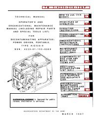
<strong>UNIT</strong> <strong>MAINTENANCE</strong> MANUAL<br />
(INCLUDING REPAIR PARTS AND SPECIAL TOOLS LIST)<br />
FOR<br />
CHEMICAL BIOLOGICAL MASK: COMBAT VEHICLE M42<br />
(<strong>4240</strong>-01-258-0064-SMALL)<br />
(<strong>4240</strong>-01-258-0065-MEDIUM)<br />
(<strong>4240</strong>-01-258-0066-LARGE)<br />
CHEMICAL BIOLOGICAL MASK: COMBAT VEHICLE M42A1<br />
(<strong>4240</strong>-01-369-7854-SMALL)<br />
(<strong>4240</strong>-01-370-2622--MEDIUM)<br />
(<strong>4240</strong>-01-369-7855-LARGE)<br />
CHEMICAL BIOLOGICAL MASK: COMBAT VEHICLE M42A2<br />
(<strong>4240</strong>-01413-4100-SMALL)<br />
(<strong>4240</strong>-01-413-4101--MEDIUM)<br />
(<strong>4240</strong>-01 4134102-LARGE)<br />
<strong>*<strong>TM</strong></strong> 3-<strong>4240</strong>-<strong>343</strong>-20&P<br />
<strong>TM</strong> <strong>09205A</strong>-20&P/2<br />
* This manual supersedes <strong>TM</strong> 3<strong>4240</strong>-300-20&P, 29 August 1994 including all changes.<br />
WARNING-This document contains export-controlled technical data whose export is restricted<br />
by the Army Export Control Act (Title 22, U.S.S.S., Sec 2751 et seq.) or Executive order 12470. Violation of<br />
these export laws is subject to severe criminal penalties.<br />
DISTRIBUTION STATEMENT-Distribution authorized to U.S. Government agencies and their<br />
contractors to protect technical or operational information. This determination was made on 24 June 1987.<br />
Other requests for this document will be referred to: Technical Director, U.S. Army, Edgewood Research,<br />
Development & Engineering Center, ATTN: SCBRD-ENL-V, Aberdeen Proving Ground, MD 21010-5423.<br />
DESTRUCTION NOTICE-Destroy by any method that will prevent disclosure of contents or<br />
reconstruction of the document.<br />
HEADQUARTERS, DEPAR<strong>TM</strong>ENT OF THE ARMY<br />
AND, HEADQUARTERS, MARINE CORPS<br />
31 JULY 1996<br />
PCN 18209205100
WARNINGS point out dangerous steps in the procedures in this manual. Your safety depends on following the<br />
instructions included in all WARNINGS. Several general WARNINGS are included below.<br />
• The mask will not be fully effective in confined spaces when the oxygen content of the air is too low. The CB<br />
mask has only been tested and verified to protect against all known military agents.<br />
• DO NOT touch your skin (or the soldier) with n-Amyl acetate (banana oil). It could irritate the skin. Wear rubber<br />
gloves.<br />
• DO NOT smoke around n-Amyl acetate (banana oil), it is flammable.<br />
• DO NOT test mask assembly with n-Amyl acetate (banana oil) in a closed, poorly ventilated area. Test outdoors<br />
or in a well-aired room, n-Amyl acetate may be toxic if inhaled in quantity.<br />
• DO NOT wear contact lenses (soft or hard) while wearing CB Protective Masks. Inadequate oxygen supply to<br />
the corneal surface, exposure to dust, dirt, and smoke/gas may cause serious vision loss or eye damage.<br />
Soldiers requiring vision correction are provided optical inserts for their protective masks.<br />
HEALTH/ENVIRONMENTAL HAZARD<br />
• There are two Mask Filter Canisters, the C2 and the C2A1. The C2 canister contains Chromium VI and damaged<br />
or unusable canisters are considered Hazardous Waste. (Chromium VI is a known carcinogen if inhaled or<br />
swallowed.)<br />
• The C2A 1 canister is chromium-free but must continue to be disposed of in accordance with State and Local<br />
Environmental Laws.<br />
• DO NOT throw away damaged or unusable canisters as ordinary trash.<br />
• DO turn in damaged or unusable canisters to your hazardous waste management office or Defense Reutilization<br />
and Marketing Office (DRMO).<br />
FIRST AID<br />
For first aid refers to FM 21-1 1.
TECHNICAL MANUAL<br />
<strong>UNIT</strong> <strong>MAINTENANCE</strong> MANUAL<br />
(INCLUDING REPAIR PARTS AND SPECIAL TOOLS LIST)<br />
FOR<br />
CHEMICAL BIOLOGICAL MASK: COMBAT VEHICLE M42<br />
(<strong>4240</strong>-01-258-0064-SMALL)<br />
(<strong>4240</strong>-01-258-0065-MEDIUM)<br />
(<strong>4240</strong>-0 1-258-0066-LARGE)<br />
CHEMICAL BIOLOGICAL MASK: COMBAT VEHICLE M42A1<br />
(<strong>4240</strong>-01-369-7854--SMALL)<br />
(<strong>4240</strong>-01-370-2622-MEDIUM)<br />
(<strong>4240</strong>-01-369-7855-LARGE)<br />
CHEMICAL BIOLOGICAL MASK: COMBAT VEHICLE M42A2<br />
(<strong>4240</strong>-01-41 3-4100-SMALL)<br />
(<strong>4240</strong>-01-413-4101-MEDIUM)<br />
(<strong>4240</strong>-01-4134102-LARGE)<br />
REPORTING ERRORS AND RECOMMENDING IMPROVEMENTS<br />
<strong>*<strong>TM</strong></strong> 3-<strong>4240</strong>-<strong>343</strong>-20&P<br />
<strong>TM</strong> <strong>09205A</strong>-20&P/2<br />
DEPAR<strong>TM</strong>ENT OF THE ARMY<br />
AND HEADQUARTERS, MARINE CORPS<br />
Washington, D.C., 31 JULY 1996<br />
You can help improve this manual. If you find any mistakes or if you know of a way to improve the procedures, please<br />
let us know. Mail you letter, DA Form 2028 (Recommended Changes to Publications and Blank Forms), or DA Form<br />
2028-2 located in the back of this manual direct to: Technical Director, U.S. Army, Edgewood Research, Development<br />
& Engineering Center, ATTN: SCBRD-ENL-V, Aberdeen Proving Ground, MD 21010-5423.<br />
Marine Corps Users Submit NAVMC FORM 10772 directly to Commander, Marine Corps Logistics Base (Code 850), 814<br />
Radford Blvd., Albany, GA 31704-5000. In addition, a copy of the NAVMC 10772 or naval message should be sent to<br />
MARCORSYSCOM (Code SSCNBC), 2033 Barnett Ave., Suite 31 5, Quantico, VA 22134-5010.<br />
In either case, a reply will be sent to you.<br />
i
TABLE OF CONTENTS<br />
HOW TO USE THIS MANUAL......................................................................................................i<br />
CHAPTER 1 INTRODUCTION......................................................................................................1-3<br />
SECTION I. GENERAL INFORMATION ......................................................................................1-3<br />
SECTION II. EQUIPMENT DESCRIPTION AND DATA ...............................................................1-4<br />
SECTION III. PRINCIPLES OF OPERATION ..............................................................................1-14<br />
CHAPTER 2 <strong>UNIT</strong> <strong>MAINTENANCE</strong> INSTRUCTION.....................................................................2-1<br />
SECTION I. REPAIR PARTS, SPECIAL TOOLS, <strong>TM</strong>DE, AND SUPPORT EQUIP ......................2-3<br />
SECTION II. SERVICE UPON RECEIPT .....................................................................................2- 3<br />
SECTION III. EQUIPMENT/USER FITTING INSTRUCTIONS .....................................................2-12<br />
SECTION IV. TROUBLESHOOTING ...........................................................................................2-22<br />
SECTION V. PREVENTIVE <strong>MAINTENANCE</strong> CHECKS AND SERVICES ....................................2-28<br />
SECTION VI. HOSE ASSEMBLY CONVERSION ........................................................................2-31<br />
SECTION VII. <strong>MAINTENANCE</strong> PROCEDURES ..........................................................................2-37<br />
SECTION VIII. CLEANING AND SANITIZING .............................................................................2-59<br />
SECTION IX. PREPARATION FOR STORAGE OR SHIPMENT .................................................2-69<br />
APPENDIX A - REFERENCES .....................................................................................................A-1<br />
APPENDIX B - <strong>MAINTENANCE</strong> ALLOCATION CHART (MAC)...................................................B-1<br />
APPENDIX C - <strong>UNIT</strong> <strong>MAINTENANCE</strong> REPAIR PARTS AND SPECIAL TOOLS<br />
LIST..............................................................................................................................................C-1<br />
APPENDIX D - EXPENDABLE AND DURABLE ITEMS LIST ......................................................D-1<br />
CROSS-REFERENCE INDEXES..................................................................................................I-1<br />
INDEX...........................................................................................................................................INDEX 1<br />
ii<br />
<strong>*<strong>TM</strong></strong> 3-<strong>4240</strong>-<strong>343</strong>-20&P<br />
<strong>TM</strong> <strong>09205A</strong>-20&P/2
HOW TO USE THIS MANUAL<br />
<strong>*<strong>TM</strong></strong> 3-<strong>4240</strong>-<strong>343</strong>-20&P<br />
<strong>TM</strong> <strong>09205A</strong>-20&P/2<br />
The safest, easiest, and best way to do maintenance on the Chemical-Biological Mask, M42 / M42A1 / M42A2 is to use<br />
this manual. Learning to use this <strong>TM</strong> is as easy as reading through the next few pages. Knowing what's in this manual<br />
and how to use it will save you time and work, and will help you avoid exposing yourself to unnecessary hazards while<br />
you do your job.<br />
ORGANIZATION<br />
Page ii has a table of contents to provide easy access to the manual. Pages are numbered consecutively within each<br />
chapter; each page number is prefixed with a chapter number or appendix letter. For example, page 5 of Chapter 2 is<br />
numbered 2-5 and page 3 of appendix B is numbered B-3.<br />
This manual is divided into two chapters, four appendixes, and an alphabetical index. Chapter 2 has an index at the<br />
beginning of the chapter to provide easy access to its content. Each chapter is divided into sections. Chapter 1 contains<br />
general information pertaining to location of forms, destruction of Army material, how to store and ship the mask,<br />
procedures for reporting any improvement recommendations you may have, as well as, corrosion prevention and control.<br />
Chapter 2 gives unit maintenance instructions and includes four types of maintenance activities. These are: Service<br />
Upon Receipt; Troubleshooting or location of faults by symptoms you can detect; Preventive Maintenance Checks and<br />
Service (PMCS); and Maintenance Procedures that are used to correct faults and replace failed parts. Within the<br />
Troubleshooting and maintenance portions of this manual, you will find the material in functional group code order like<br />
the Maintenance Allocation Chart in Appendix B of this <strong>TM</strong>. This allows the <strong>TM</strong> to be aligned with its applicable Repair<br />
parts and Special Tools List (RPSTL). For information on how to use the RPSTL, refer to the introduction in Appendix C.<br />
HOW TO FIND PROCEDURES<br />
If you're using the manual to perform Troubleshooting, go to Section IV, and read TROUBLESHOOTING PROCEDURES<br />
and proceed according to the instructions there. If you're going to do Scheduled Maintenance, you can turn directly to<br />
Preventive Maintenance Checks and Services (PMCS), Section V, and proceed according to the instructions there.<br />
If you are using the manual to perform repair or replacement of a part that you already know is bad, you would start by<br />
locating the part to be replaced in the Alphabetical index located at the back of this manual. Look in the Alphabetical<br />
Index for a key noun from the mask system or part nomenclature. The Alphabetical Index lists each task under one or<br />
more headings also giving the location for the installation and removal of some part. For example, the procedure for<br />
CLEANING AND SANITIZING would be listed under "C" for Cleaning.<br />
Once you've located the correct procedure, read through it to determine if you have everything you need to perform the<br />
job. Make sure all the Equipment Conditions have been met. Familiarize yourself with the potential hazards described<br />
by the WARNINGS and CAUTIONS. You must familiarize yourself with the entire maintenance procedure before<br />
beginning the maintenance task.<br />
HOW TO USE A <strong>MAINTENANCE</strong> PROCEDURE<br />
The first page of a maintenance procedure lists everything you will need to perform that procedure. The following<br />
paragraphs describe all the blocks of information you will find there.<br />
TOOLS. Individual tools from your mechanic's tool kit will not be listed under this heading. If any tools from this kit are<br />
required, the tool kit itself will be listed as the first item. Special tools, and tools from any other source will be listed with<br />
a reference to a specific item and appendix number. The referenced appendix will provide you with the necessary<br />
information to find or make the tool.<br />
SUPPLIES. If any expendable or consumable supplies are needed to perform the task, they will be listed under this<br />
heading along with the quantity in parentheses and a reference to a figure item and appendix in the back of the <strong>TM</strong>. The<br />
referenced appendix will give you the detailed information necessary to requisition the supply if you don't have it on<br />
hand. Replacement parts are not normally listed under this heading. The inspection steps in the removal or disassembly<br />
procedure will tell you which parts to replace. Mandatory repair parts ( parts that are destroyed in disassembly or not<br />
normally reused, such as gaskets and lock washers) are listed under this heading by their nomenclature only. Refer to<br />
Repair Parts and Special Tools List (RPSTL), Appendix C for information you need on repair parts.<br />
iii
CHEMICAL BIOLOGICAL MASKS<br />
1-0<br />
<strong>*<strong>TM</strong></strong> 3-<strong>4240</strong>-<strong>343</strong>-20&P<br />
<strong>TM</strong> <strong>09205A</strong>-20&P/2
CHAPTER 1<br />
INTRODUCTION<br />
<strong>*<strong>TM</strong></strong> 3-<strong>4240</strong>-<strong>343</strong>-20&P<br />
<strong>TM</strong> <strong>09205A</strong>-20&P/2<br />
SECTION I. GENERAL INFORMATION<br />
1-1. SCOPE<br />
a. Type of Manual. Unit maintenance.<br />
b. Model Numbers and Equipment Name. Chemical-biological (CB ) mask: combat vehicle M42, M42A1, and<br />
M42A2.<br />
c. Purpose of Equipment. Protects the face, eyes, and lungs from field concentrations of CB agents, toxins, and<br />
radioactive fallout particles.<br />
1-2. <strong>MAINTENANCE</strong> FORMS, RECORDS, AND REPORTS<br />
a. Department of the Army forms and procedures used for equipment maintenance will be those prescribed by DA<br />
PAM 738-750, The Army Maintenance Management System (TAMMS), as contained in the Maintenance<br />
Management update.<br />
b. Marine Corps forms and procedures used for equipment maintenance are prescribed in <strong>TM</strong> 4700-15/1.<br />
1-3. DESTRUCTION OF ARMY MATERIAL TO PREVENT ENEMY USE<br />
• Refer to <strong>TM</strong> 43-0002-31 for methods of destruction.<br />
1-4. PREPARATION FOR STORAGE OR SHIPMENT<br />
• Refer to Chapter 2, Section IX, for preparation for storage or shipment.<br />
1-5. REPORTING EQUIPMENT IMPROVEMENT RECOMMENDATIONS (EIR)<br />
a. If you have ideas on how the M42 series masks can be changed or maintained more effectively, let us know.<br />
Send us an EIR. You, the user, are the only one who can tell us what you don't like about your equipment. Let<br />
us know why you don't like the design. Put it on an SF 368 (Quality Deficiency Report). Mail it to us at Director,<br />
US Army Armament and Chemical Acquisition and Logistics Activity, ATTN: AMSTA-AR-QAW-A (RI), Rock<br />
Island, IL 61299-7630. We'll send you a reply.<br />
b. Marine Corps users shall submit a Standard Form 368 (SF368) in accordance with MCO 4855.10 directly to:<br />
Commander, Marine Corps Logistics Base (Code 856), 814 Radford Blvd., Albany, GA 31704-5000. We will<br />
send you a reply.<br />
1-6. CORROSION PREVENTION AND CONTROL (CPC)<br />
a. CPC of Army material is a continuing concern. It is important that any corrosion problems with this item be<br />
reported so that the problem can be corrected and improvements can be made to prevent the problem in future<br />
items.<br />
b. While corrosion is typically associated with rusting of metals, it can also include deterioration of other materials<br />
such as rubber and plastic. Unusual cracking, softening, swelling, or breaking of these materials may be a<br />
corrosion problem.<br />
c. If a corrosion problem is identified, it can be reported using a Quality Deficiency Report, SF 368. Use of key<br />
words such as "corrosion", "rust", "deterioration", or "cracking" will assure that the information is identified as a<br />
CPC problem.<br />
d. The form should be submitted to Director, US Army Armament and Chemical Acquisition and Logistics Activity,<br />
AT'N: AMSTA-AR-QAW-A (RI), Rock Island, IL 61299-7630.<br />
e. Marine Corps Units report CPC problems using SF 368 and procedures prescribed in <strong>TM</strong> 4700-15/1.<br />
1-1
SECTION II. EQUIPMENT DESCRIPTION AND DATA<br />
1-7. EQUIPMENT CHARACTERISTICS, CAPABILITIES, AND FEATURES.<br />
<strong>*<strong>TM</strong></strong> 3-<strong>4240</strong>-<strong>343</strong>-20&P<br />
<strong>TM</strong> <strong>09205A</strong>-20&P/2<br />
The lightweight, chemical-biological masks (M42 / M42A 1 / M42A2 ) consist of a facepiece, canister and hose which is<br />
easy to assemble for transport and storage. The mask assembly is kept dry, when required by climate and mission, by a<br />
waterproof bag and stored in a carrier made of mildew-resistant, water repellent, coated nylon.<br />
The facepiece is made of silicone rubber with an inturned sealing surface so it can provide protection to face, eyes, and<br />
respiratory tract from CB agents, toxins and radioactive particles. The mask assembly is not intended for use in an<br />
oxygen deficient environment. Nor is it intended to provide protection against carbon monoxide or ammonia. It forms a<br />
comfortable seal on a soldier's face as it protects against adverse elements. The mask assembly is equipped with both<br />
front and side voicemitters for ease of communication and an outlet valve body with a drinking system. To ensure a<br />
comfortable fit, the mask assembly is issued in three sizes: small, medium and large which are marked with S, M and L<br />
on the forehead to show sizing. It is also equipped with clear and neutral gray outserts to protect the eyelens from<br />
scratches, reduce sun glare and prevent fogging in cold weather. The M42, M42A 1, and M42A2 masks have<br />
microphone communication capability that can couple with on board communication systems, through the Combat<br />
Vehicle Communications (CVC) helmet.<br />
The M42A1 and M42A2 masks have a second skin, universal second skin, or universal second skin (USMC) which fits to<br />
the facepiece and protects the facepiece from liquid agents, and a quick doff hood made of lightweight, butyl rubbercoated<br />
fabric, which provides protection to the head and neck from liquid toxic chemical agents. The second skin,<br />
universal second skin, or universal second skin (USMC) is issued in two sizes: small and medium/large which are<br />
marked S and M/L on the exterior left cheek.<br />
1-8. LOCATION AND DESCRIPTION OF MAJOR COMPONENTS<br />
a. FACEPIECE ASSEMBLY<br />
• FACEPIECE (1). The following components are molded/assembled into the silicone rubber facepiece:<br />
buckle tabs, facepiece openings for eyelens, nosecup, voicemitters, outlet valve, and canister/hose connectors.<br />
• HEAD HARNESS (2). Constructed of elastic webbing sewn to a rectangular head pad and buckled to<br />
facepiece. The ends of the head harness straps have metal strap end clips to prevent fraying of the elastic webbing.<br />
Ends of the head harness straps pass through buckles at the two forehead, temple and cheek positions. Elastic webbing<br />
connects the two forehead straps and holds them in proper alignment when the mask assembly is worn. Head harness<br />
straps attached to buckles at the ends of the tabs permit adjustment to obtain proper fit of the mask assembly.<br />
1-2
1-8. LOCATION AND DESCRIPTION OF MAJOR COMPONENTS (CONT)<br />
<strong>*<strong>TM</strong></strong> 3-<strong>4240</strong>-<strong>343</strong>-20&P<br />
<strong>TM</strong> <strong>09205A</strong>-20&P/2<br />
• NOSECUP ASSEMBLY (3). Made of soft rubber; fits over the soldier's nose and mouth. Diverts exhaled air<br />
toward the outlet valve to reduce fogging of the eyelens.<br />
NOTE<br />
The M42 has a black nosecup; the M42A1 and M42A2 have an improved green nosecup.<br />
• NOSECUP VALVE SEATS (4). Each of two nosecup valve seats holds silicone rubber NOSECUP VALVE DISK<br />
(5), which allows filtered air to enter nosecup and prevent moist exhaled air from fogging the eyelens in cold<br />
weather.<br />
• INTERNAL DRINK TUBE (6). Allows the soldier to drink while wearing the mask assembly.<br />
• AIRFLOW DEFLECTOR (7), located inside the mask assembly, directs inhaled air over eyelens to reduce<br />
fogging. The airflow deflector also supports the inlet valve disk and the inlet valve body.<br />
• INLET VALVE BODY (8) and INLET VALVE DISK (9), fits into the airflow deflector, allows filtered air to enter the<br />
mask assembly and prevent moist exhaled air from entering the canister.<br />
• OUTLET VALVE COVER (10). Protects outlet valve disk and outlet valve housing from damage.<br />
• RETAINER (11). Holds external drink tube quick disconnect coupling.<br />
• OUTLET VALVE DISK (12) and OUTLET VALVE HOUSING (13). Located behind outlet valve cover; releases<br />
exhaled air and closes on inhalation to prevent contaminated air from entering mask assembly.<br />
• FRONT(14) AND SIDE VOICEMITTERS (15). Transmits the soldier's voice outside the mask assembly.<br />
• EXTERNAL DRINK TUBE (16). The External Drink Tube is used to connect the mask assembly to the M1<br />
Canteen cap for drinking. It consists of a length of hose and a quick disconnect coupling half (17) that fits into<br />
the external drink tube retainer.<br />
1-3
1-8. LOCATION AND DESCRIPTION OF MAJOR COMPONENTS (CONT)<br />
<strong>*<strong>TM</strong></strong> 3-<strong>4240</strong>-<strong>343</strong>-20&P<br />
<strong>TM</strong> <strong>09205A</strong>-20&P/2<br />
Microphone (M42 / M42A 1 / M42A2). Facilitates the use of a radio while wearing the mask assembly and can be<br />
coupled into CVC helmet by the microphone cord.<br />
• MICROPHONE (18) AND MICROPHONE CORD (19) (M42 and M42A1 only). Located inside nosecup area of<br />
mask assembly. Microphone cord plugs into the microphone receptacle located on the exterior of the front<br />
voicemitter.<br />
• DETACHABLE MICROPHONE (20) WITH CORD. Located in the recess of the front voicemitter.<br />
1-4
1-8. LOCATION AND DESCRIPTION OF MAJOR COMPONENTS (CONT)<br />
b. CANISTER CARRIER (21) (M42 / M42A 1 / M42A2)<br />
<strong>*<strong>TM</strong></strong> 3-<strong>4240</strong>-<strong>343</strong>-20&P<br />
<strong>TM</strong> <strong>09205A</strong>-20&P/2<br />
NOTE<br />
You may have been issued the M42 canister carrier or the product improved model of the<br />
canister carrier. They are interchangeable.<br />
• Permits the user to support the filter canister outside of the mask carrier.<br />
• Can hold a variety of NATO (North Atlantic Treaty Organization) filter canisters ( M42A 1 and M42A2 only).<br />
• ARMOR QUICK DISCONNECT (22). Attached to the canister cover (23) and permits the filter canister to be<br />
coupled to a vehicle's Gas Particulate Filter Unit (GPFU). The Armor quick disconnect is not detachable (M42<br />
Only).<br />
• FILTER CANISTER (24) filters out CB agents and other particles from contaminated air.<br />
1-5
1-8. LOCATION AND DESCRIPTION OF MAJOR COMPONENTS (CONT)<br />
<strong>*<strong>TM</strong></strong> 3-<strong>4240</strong>-<strong>343</strong>-20&P<br />
<strong>TM</strong> <strong>09205A</strong>-20&P/2<br />
c. HOSE ASSEMBLY (25). The hose assembly connects the filter canister and canister carrier to the mask<br />
assembly.<br />
CAUTION<br />
DO NOT remove the hose assembly on the M42 mask. Removal of hose assembly will render the<br />
mask unserviceable.<br />
• M42 The hose assembly is permanently attached to the side of the M42 mask assembly.<br />
• M42A1 and M42A2 The hose assembly is attached to the mask assembly with the STAR KNOB (26). The hose<br />
assembly is removable and can be relocated on left or right side of the M42A1 or M42A2 mask assembly.<br />
NOTE<br />
The soldier may be issued either the one piece hood OR the quick doff hood and second skin OR<br />
universal second skin and quick doff hood or hooded overgarment OR the universal second skin<br />
(USMC) and hooded overgarment. They are identical in function and effectiveness. However, the<br />
one piece hood may not be removed during decon operations.<br />
d. ONE PIECE HOOD (27) (M42 only). Provides protection to the head and neck against liquid toxic chemical<br />
agents encountered in field operations. Made of lightweight butyl rubber-coated fabric. It is attached to the mask<br />
assembly during use and stowed in mask carrier.<br />
1-6
1-8. LOCATION AND DESCRIPTION OF MAJOR COMPONENTS (CONT)<br />
e. QUICK DOFF HOOD (M42A1 and M42A2 only).<br />
<strong>*<strong>TM</strong></strong> 3-<strong>4240</strong>-<strong>343</strong>-20&P<br />
<strong>TM</strong> <strong>09205A</strong>-20&P/2<br />
• QUICK DOFF HOOD (28). Is made of butyl rubber-coated fabric, which protects area of neck and head that is<br />
not covered by mask assembly against CB agents, toxins, and radioactive fallout particles.<br />
• ELASTIC AROUND OPENING (29). Attaches quick doff hood to the second skin. It enables easy removal of<br />
the quick doff hood.<br />
• ELASTIC AROUND NECK (30). Draws quick doff hood close to the neck to protect from CB agents.<br />
• UNDERARM STRAPS (31). Retain quick doff hood on the shoulders. Plastic fasteners (32) are used to attach<br />
the straps.<br />
f. SECOND SKIN (M42A1 / M42A2).<br />
• SECOND SKIN (33) ( M42AI / M42A2). Is made of butyl rubber, and covers facepiece to protect from chemicalbiological<br />
(CB) agents, toxins, and radioactive fallout particles.<br />
• RUBBER CATCHES (34) ( M42A1 / M42A2). Retains the quick doff hood to the second skin and facepiece;<br />
located at the top and bottom of the second skin. RIDGE (35) ( M42A I / M42A2) is used as a secondary source<br />
of retention for the quick doff hood.<br />
1-7
1-8. LOCATION AND DESCRIPTION OF MAJOR COMPONENTS-(CONT)<br />
<strong>*<strong>TM</strong></strong> 3-<strong>4240</strong>-<strong>343</strong>-20&P<br />
<strong>TM</strong> <strong>09205A</strong>-20&P/2<br />
g. UNIVERSAL SECOND SKIN (36) (M42A 1 / M42A2). Is made of butyl rubber and covers the facepiece. It<br />
provides additional protection against liquid agents.<br />
• Interfaces with hooded overgarments.<br />
• Extends beyond the mask facepiece.<br />
h. UNIVERSAL SECOND SKIN (USMC only) (37). Is made of butyl rubber and covers the facepiece. It provides<br />
additional protection against liquid agents.<br />
• Interfaces with hooded overgarments.<br />
• Extends beyond the mask facepiece.<br />
i CLEAR OUTSERTS (38) and NEUTRAL GRAY OUTSERTS (39). Each outsert is seated in a soft rubber ring<br />
that fits over the mask assembly eyelens rings. The rim of the rubber ring fits snugly behind the eyering to<br />
protect the eyelens from scratches. Neutral gray outserts are used to reduce sun glare. The outserts also reduce<br />
fogging.<br />
j. M1 WATERPROOF BAG (40). The folded waterproof bag and a small envelope containing the RUBBER<br />
BANDS (41) are packed in carrier. Instructions for use are printed on the waterproof bag.<br />
1-8
1-8. LOCATION AND DESCRIPTION OF MAJOR COMPONENTS-(CONT)<br />
k. FACEFORM (42)<br />
• Holds mask assembly in proper shape when stored longer than 30 days.<br />
<strong>*<strong>TM</strong></strong> 3-<strong>4240</strong>-<strong>343</strong>-20&P<br />
<strong>TM</strong> <strong>09205A</strong>-20&P/2<br />
NOTE<br />
The soldier may be issued either mask carrier. Major differences are size and accessory stowage<br />
locations.<br />
1. Mask Carrier is made of mildew-resistant, water-repellant fabric. It has adjustable straps. It is closed with a flap<br />
held by hook and pile material.<br />
• FIELD MASKCARRIER (43).<br />
• COMBAT VEHICLE MASK CARRIER (44). This mask carrier has been redesigned to prevent dirt from entering<br />
the mask carrier. It also was enlarged to include larger accessory pockets.<br />
1-9
1-9. DIFFERENCE BETWEEN MODELS<br />
This chart shows major equipment and differences between the M42, M42AI, and M42A2.<br />
Table 1-1. Differences Between Models<br />
<strong>*<strong>TM</strong></strong> 3-<strong>4240</strong>-<strong>343</strong>-20&P<br />
<strong>TM</strong> <strong>09205A</strong>-20&P/2<br />
MASK FEATURES CHEMICAL BIOLOGICAL MASK<br />
M42 M42A1 M42A2<br />
Facepiece X X X<br />
Canister is connected to end coupling of hose assembly X X X<br />
Detachable star knob hose assembly X X<br />
Clamped hose attached directly to facepiece (NOT DETACHABLE) X<br />
Hood (One-Piece) X<br />
Quick Doff Hood X X<br />
Second Skin X X<br />
Universal Second Skin X X X<br />
Universal Second Skin (USMC only) X X X<br />
Clear/Neutral Outserts X X X<br />
Microphone (Internal) X X<br />
Detachable Microphone (External) X<br />
Front and Side Voicemitter X X X<br />
Field Mask Carrier X X X<br />
Combat Vehicle Mask Carrier X X X<br />
Operation Capabilities:<br />
Combat Vehicle X X X<br />
Transportable and stored in carrier X X X<br />
1-10
1-10. EQUIPMENT DATA<br />
a. Tabulated Data<br />
Weight (with carrier and accessories):<br />
M42 4.5 lbs. (2.05 kg)<br />
M42A1 mask. 4.5 lbs. (2.05 kg)<br />
M42A2 mask. 4.5 lbs. (2.05 kg)<br />
Dimensions: Mask with carrier...12 x 14 x 4.5 in. (30.5 x 35.6 x 11.4 cm.)<br />
b. Shipping and Storage Data.<br />
Number and type of pack: 10 per fiberboard container; I per fiberboard box.<br />
Fiberboard container:<br />
Dimensions: 34.375 x 22 x 16.75 in. (87 x 55.9 x 42.5 cm)<br />
1-11<br />
<strong>*<strong>TM</strong></strong> 3-<strong>4240</strong>-<strong>343</strong>-20&P<br />
<strong>TM</strong> <strong>09205A</strong>-20&P/2
1-11. PRINCIPLES OF OPERATION<br />
SECTION III. PRINCIPLES OF OPERATION<br />
a. The M42 /M42A 1 /M42A2 chemical-biological masks consists of:<br />
1. Silicone FACEPIECE (1) which fits closely against soldier's face to form a seal;<br />
2. HOSE(2).<br />
3. CANISTER CARRIER (3) with filter canister inside.<br />
<strong>*<strong>TM</strong></strong> 3-<strong>4240</strong>-<strong>343</strong>-20&P<br />
<strong>TM</strong> <strong>09205A</strong>-20&P/2<br />
4. The ONE PIECE HOOD (4) (M42 ) made of lightweight butyl rubber-coated fabric which provides protection to<br />
the head and neck from liquid toxic chemical agents.<br />
1-12
1-11. PRINCIPLES OF OPERATION (CONT)<br />
<strong>*<strong>TM</strong></strong> 3-<strong>4240</strong>-<strong>343</strong>-20&P<br />
<strong>TM</strong> <strong>09205A</strong>-20&P/2<br />
5. QUICK DOFF HOOD (5) (M42A1 / M42A2 ) made of lightweight butyl rubber-coated fabric which provides<br />
protection to the head and neck from liquid toxic chemical agents.<br />
6. SECOND SKIN (6) ( M42A 1 / M42A2 ) which fits to the facepiece and protects the facepiece from liquid agents.<br />
7. UNIVERSAL SECOND SKIN(7) (M42A1 /M42A2). which fits to the facepiece and protects the facepiece from<br />
liquid agents and for use with either the quick doff hood or a hooded overgarments.<br />
8. UNIVERSAL SECOND SKIN (USMC only) (8) which fits to the facepiece and protects the facepiece from liquid<br />
agents and for use with either the quick doff hood or a hooded overgarments.<br />
1-13
1-11. PRINCIPLES OF OPERATION (CONT)<br />
<strong>*<strong>TM</strong></strong> 3-<strong>4240</strong>-<strong>343</strong>-20&P<br />
<strong>TM</strong> <strong>09205A</strong>-20&P/2<br />
9. MICROPHONE (9) (internal) ( M42 / M42A 1 ) and DETACHABLE MICROPHONE (10) (external) connects to<br />
CVC helmet and enables radio communication.<br />
b. Air enters the filter canister, which is held in the CANISTER CARRIER (11). The canister filters out CB agents,<br />
toxins, and radioactive fallout particles from contaminated air. Air then passes through the HOSE (12) and<br />
DEFLECTOR (13) which is located inside the mask assembly. The air then moves into the eye area of the mask<br />
assembly.<br />
c. From the eye area, air enters the NOSECUP (14) through NOSECUP VALVES (15). Filtered air from the<br />
nosecup is inhaled by the soldier. Exhaled air is passed through the nosecup area and out through the outlet<br />
valve. The OUTLET VALVE COVER (16) protects the outlet valve from contamination and damage, and<br />
provides a retainer for the external drink tube.<br />
1-14
1-11. PRINCIPLES OF OPERATION (CONT)<br />
<strong>*<strong>TM</strong></strong> 3-<strong>4240</strong>-<strong>343</strong>-20&P<br />
<strong>TM</strong> <strong>09205A</strong>-20&P/2<br />
d. Outserts have RUBBER RINGS (17) that fit over mask assembly eyelens rings to secure outserts to mask<br />
assembly. The CLEAR (18) and NEUTRAL GRAY OUTSERTS (19) prevent scratching of eyelens and reduce<br />
fogging of eyelens in cold weather.<br />
e. WATERPROOF BAG (20) keeps mask dry when required by climate and mission.<br />
f. FIELD MASK CARRIER (21) and COMBAT VEHICLE MASK CARRIER (22) provide storage and carrying of<br />
mask assembly along with additionally authorized items (see operator's manual).<br />
1-15 (1-16 blank)
Table of Contents<br />
CHAPTER 2 <strong>UNIT</strong> <strong>MAINTENANCE</strong> INSTRUCTIONS<br />
Para. Page<br />
SECTION I. REPAIR PARTS, SPECIAL TOOLS, <strong>TM</strong>DE, AND SUPPORT<br />
EQUIPMENT ...........................................................................................................................2-3<br />
2-1. COMMON TOOLS AND EQUIPMENT..................................................................................2-3<br />
2-2. SPECIAL TOOLS, <strong>TM</strong>DE, AND SUPPORT EQUIPMENT.....................................................2-3<br />
2-3. REPAIR PARTS....................................................................................................................2-3<br />
SECTION II. SERVICE UPON RECEIPT.....................................................................................2-3<br />
2-4. GENERAL.............................................................................................................................2-3<br />
2-5. SERVICE UPON RECEIPT OF MATERIAL ..........................................................................2-3<br />
2-6. IDENTIFYING AN INDIVIDUAL'S MASK...............................................................................2-12<br />
SECTION III. EQUIPMENT/USER FITTING INSTRUCTIONS.....................................................2-13<br />
2-7. ADJUSTING MASK ASSEMBLY AT INITIAL FITTING..........................................................2-13<br />
2-8. CHECKING MASK ASSEMBLY FOR PROPER FUNCTION.................................................2-17<br />
2-9. CHECKING DRINKING SYSTEM FOR PROPER FUNCTION ..............................................2-21<br />
SECTION IV. TROUBLESHOOTING ..........................................................................................2-23<br />
2-10. TROUBLESHOOTING PROCEDURES...............................................................................2-23<br />
SECTION V. PREVENTATIVE <strong>MAINTENANCE</strong> CHECKS AND SERVICES<br />
(PMCS)....................................................................................................................................2-29<br />
2-11. INTRODUCTION TO PMCS TABLE ...................................................................................2-29<br />
2-12. PMCS PROCEDURES........................................................................................................2-29<br />
SECTION VI. HOSE ASSEMBLY CONVERSION........................................................................2-33<br />
2-13. LEFT/RIGHT HOSE ASSEMBLY CONVERSION................................................................2-33<br />
2-1<br />
<strong>*<strong>TM</strong></strong> 3-<strong>4240</strong>-<strong>343</strong>-20&P<br />
<strong>TM</strong> <strong>09205A</strong>-20&P/2
Table of Contents<br />
Para. Page<br />
SECTION VII. <strong>MAINTENANCE</strong> PROCEDURES ..........................................................................2-39<br />
2-14. GENERAL...........................................................................................................................2-39<br />
Facepiece Assembly<br />
2-15. INTERNAL DRINK TUBE....................................................................................................2-40<br />
2-16. QUICK DISCONNECT COUPLING, EXTERNAL DRINK TUBE ..........................................2-42<br />
2-17. HEAD HARNESS................................................................................................................2-43<br />
2-18. SECOND SKIN ...................................................................................................................2-44<br />
2-19. UNIVERSAL SECOND SKIN...............................................................................................2-46<br />
2-20. UNIVERSAL SECOND SKIN (USMC only)..........................................................................2-48<br />
2-21. NOSECUP VALVE DISKS ..................................................................................................2-50<br />
2-22. AIRFLOW DEFLECTOR, INLET VALVE, AND VALVE BODY ............................................2-51<br />
2-23. OUTLET VALVE COVER AND OUTLET VALVE DISK .......................................................2-55<br />
2-24. MICROPHONE ...................................................................................................................2-57<br />
2-25. DETACHABLE MICROPHONE ...........................................................................................2-58<br />
2-26. SIDE VOICEMITTER, VOICEMITTER RETAINER, AND GASKET.....................................2-59<br />
Canister Carrier<br />
2-27. CANISTER COVER ............................................................................................................2-60<br />
2-28. ARMOR QUICK DISCONNECT (AQD) ...............................................................................2-61<br />
Hose Assembly<br />
2-29. CLAMP COVER..................................................................................................................2-62<br />
2-30. PORT GASKET ..................................................................................................................2-63<br />
Optical Equipment<br />
2-31. OPTICAL INSERT KIT ........................................................................................................2-64<br />
2-2<br />
<strong>*<strong>TM</strong></strong> 3-<strong>4240</strong>-<strong>343</strong>-20&P<br />
<strong>TM</strong> <strong>09205A</strong>-20&P/2
2-1. COMMON TOOLS AND EQUIPMENT<br />
CHAPTER 2<br />
<strong>UNIT</strong> <strong>MAINTENANCE</strong> INSTRUCTIONS<br />
SECTION I. REPAIR PARTS, SPECIAL TOOLS, <strong>TM</strong>DE, AND SUPPORT<br />
EQUIPMENT<br />
<strong>*<strong>TM</strong></strong> 3-<strong>4240</strong>-<strong>343</strong>-20&P<br />
<strong>TM</strong> <strong>09205A</strong>-20&P/2<br />
• For authorized common tools and equipment, refer to the Modified Table of Organization and Equipment<br />
(MTOE) applicable to your unit.<br />
2-2. SPECIAL TOOLS, <strong>TM</strong>DE, AND SUPPORT EQUIPMENT<br />
• Special tools, <strong>TM</strong>DE, and support equipment required are listed in Appendix C-Repair Parts and Special Tools<br />
List (RPSTL) and Appendix B-Maintenance Allocation Chart (MAC).<br />
2-3. REPAIR PARTS<br />
• Repair parts are listed and illustrated in Appendix C of this manual.<br />
2-4. GENERAL<br />
SECTION II. SERVICE UPON RECEIPT<br />
• This section contains instructions and procedures for services to be performed upon receipt of a new mask.<br />
These services include unpacking and checking the mask.<br />
2-5. SERVICE UPON RECEIPT OF MATERIAL<br />
• Table 2-1 contains instructions for performing the services required upon receipt of this equipment.<br />
2-3
2-5. SERVICE UPON RECEIPT OF MATERIAL<br />
Table 2-1. Service upon receipt -- M42 / M42A1 M42A2 Masks<br />
<strong>*<strong>TM</strong></strong> 3-<strong>4240</strong>-<strong>343</strong>-20&P<br />
<strong>TM</strong> <strong>09205A</strong>-20&P/2<br />
LOCATION ITEM ACTION REMARKS<br />
UNPACKING WARNING<br />
After removing the top of a wood<br />
1. OUTER BOX, Flaps (fiberboard box) or box, remove nails or bend nails to<br />
FIBERBOARD OR top (wood box)<br />
WOOD,AS APPLI-<br />
CABLE NOTE<br />
If possible, retain some shipping<br />
boxes for possible future turn-ins.<br />
Open box by cutting tape and<br />
banding on fiberboard boxes or<br />
remove top by cutting banding<br />
and prying open top of wood<br />
boxes. Remove nails or bend<br />
nails over to prevent injury.<br />
Remove inner fiberboard boxes.<br />
Remove barrier bar around<br />
facepiece folder.<br />
NOTE<br />
(M42A1 /M42A2) Second skin,<br />
or universal second skin is packaged<br />
on top of the facepiece in<br />
the facepiece holder.<br />
2. INNER FIBER- a. Microphone ( M42 Open inner box. Remove<br />
BOARD BOX M42A1 ) facepiece microphone (1) (M42 / M42A)<br />
fiberboard folder, and discard poly-bag.<br />
outserts, and second<br />
skin or universal<br />
second skin.<br />
Take clear (2) and neutral gray<br />
(3) outserts out of bags and<br />
discard bags.<br />
2-4
2-5. SERVICE UPON RECEIPT OF MATERIAL<br />
Table 2-1. Service upon receipt -- M42/M42A1 /M42A2 Masks<br />
<strong>*<strong>TM</strong></strong> 3-<strong>4240</strong>-<strong>343</strong>-20&P<br />
<strong>TM</strong> <strong>09205A</strong>-20&P/2<br />
LOCATION ITEM ACTION REMARKS<br />
UNPACKING(CONT)<br />
2. INNER FIBER- a. Microphone ( M42/<br />
NOTE<br />
Masks stored more than 30 days<br />
shall be stored with faceform in mask<br />
BOARD BOX (CONT) M42A1) facepiece assembly. Keep all faceforms. Do<br />
fiberboard folder,<br />
outserts, and second<br />
Not Discard.<br />
skin, or universal Remove facepiece folder (4).<br />
second skin. (Cont) Remove facepiece (5) and second<br />
skin (6), or universal second skin<br />
(7) and discard both folder and<br />
bag.<br />
b. Facepiece and Loosen head harness straps of<br />
faceform. facepiece and remove faceform (8).<br />
Cut tabs (9) where indicated. Store<br />
at organization level.<br />
Remove protective poly-covering<br />
(10) from eyelenses (11) by pulling<br />
covering away from eyelens to<br />
stretch, then forward to remove.<br />
Discard protective covering.<br />
c. Mask Carrier (M42/ Take field mask carrier (12) out of<br />
M42A1) bag and discard bag.<br />
2-5
2-5. SERVICE UPON RECEIPT OF MATERIAL<br />
Table 2-1. Service upon receipt -- M42 / M42A1 / M42A2 Masks<br />
<strong>*<strong>TM</strong></strong> 3-<strong>4240</strong>-<strong>343</strong>-20&P<br />
<strong>TM</strong> <strong>09205A</strong>-20&P/2<br />
LOCATION ITEM ACTION REMARKS<br />
UNPACKING(CONT) d. Mask Carrier (M42A2). Take combat vehicle mask<br />
carrier (13) out of bag and<br />
discard bag.<br />
e. Quick doff hood Take quick doff hood (14) out<br />
(M42A1/M42A2). of bag and discard bag.<br />
f. Microphone cord (M42A1/ Remove microphone cord (15)<br />
M42A1) from bag and discard bag.<br />
g. Detachable microphone Take detachable microphone<br />
(M42A2). (16) out of bag and discard bag.<br />
h. Canister Carrier (M42). Take canister carrier (17) out of<br />
bag and discard bag.<br />
2-6
2-5. SERVICE UPON RECEIPT OF MATERIAL<br />
Table 2-1. Service upon receipt -- M42/ M42A1 /M42A2 Masks<br />
<strong>*<strong>TM</strong></strong> 3-<strong>4240</strong>-<strong>343</strong>-20&P<br />
<strong>TM</strong> <strong>09205A</strong>-20&P/2<br />
LOCATION ITEM ACTION REMARKS<br />
UNPACKING<br />
(CONT) i. Canister Carrier (M42A 1/ Take canister carrier (18) out of bag<br />
M42A2) and discard bag.<br />
j. Vacuum sealed can Store unopened can (19) until iscontaining<br />
filter sued. Record lot number of filter<br />
canister. canister in accordance with unit<br />
SOP.<br />
k. Hose assembly Take hose assembly (20) out of<br />
(M42A/ M42A2). bag and discard bag.<br />
1. Waterproof bag Remove waterproof bag (21) in<br />
self-sealing plastic bag (22) from<br />
field mask carrier (M42 / M42A 1),<br />
combat vehicle mask carrier<br />
(M42A2). Check that three rubber<br />
bands (23) are included. Return<br />
waterproof bag and rubber bands<br />
to self-sealing bag.<br />
m. Heat sealed bag- Take manual (24) out of bag. Bag<br />
manual may be retained to protect manual.<br />
2-7
2-5. SERVICE UPON RECEIPT OF MATERIAL<br />
Table 2-1. Service upon receipt -- M42 / M42A1/ M42A2 Masks<br />
<strong>*<strong>TM</strong></strong> 3-<strong>4240</strong>-<strong>343</strong>-20&P<br />
<strong>TM</strong> <strong>09205A</strong>-20&P/2<br />
LOCATION ITEM ACTION REMARKS<br />
INSPECTION Inspect equipment for damage<br />
incurred during shipment. If<br />
equipment has been damaged,<br />
report the damage on SF 364,<br />
Report of Discrepancy (ROD).<br />
Check equipment against packing<br />
slip to see if shipment is complete.<br />
Report all discrepancies in<br />
accordance with the instructions<br />
PREPARING TO a. Second skin or Install Second Skin (6) (para 2-<br />
STOW THE MASK universal second 18) or universal second skin (7)<br />
CARRIER skin (M42A1/ (para 2-19) on facepiece (5).<br />
M42A2)<br />
b. Clear outserts Install clear Outserts (2) on<br />
facepiece (see Operator's<br />
Manual).<br />
c. Microphone and Plug microphone cord (15) into mi-<br />
Microphone cord crophone receptacle located on the<br />
(M42/M42A1). exterior of the front voicemitter.<br />
Route cord behind outlet valve<br />
cover (25) (para 2-24).<br />
d. Detachable Micro- Attach detachable microphone (16)<br />
phone(M42A2). to front voicemitter opening of<br />
facepiece (para 2-25).<br />
2-8
2-5. SERVICE UPON RECEIPT OF MATERIAL<br />
Table 2-1. Service upon receipt -- M42 / M42A1 / M42A2 Masks<br />
<strong>TM</strong> 3-<strong>4240</strong>-<strong>343</strong>-20&P<br />
<strong>TM</strong> <strong>09205A</strong> - 20&P/2<br />
LOCATION ITEM ACTION REMARKS<br />
e. Mask assembly Record 13 digit alphanumeric<br />
PREPARING TO number (26) in a property book<br />
STOW THE MASK or log IAW unit SOP.<br />
CARRIER (CONT)<br />
f. Hose Assembly Attach the hose assembly (20) to<br />
the mask assembly (5) (see<br />
Operator's Manual).<br />
g. Mask assembly (27) Place faceform (12) into mask<br />
(mask assembly, hood, assembly. Place neatly folded<br />
head harness and face- quick doff hood (l4) (M42AI/<br />
form). M42A2) into back of faceform.<br />
Tighten head harness to hold<br />
quick doff hood.<br />
h. Mask assembly (28) Place faceform into mask<br />
(mask assembly, hood, assembly. Tighten head harness<br />
head harness and face- to hold faceform.<br />
form). (For use with<br />
hooded overgarments.)<br />
2-9
2-5. SERVICE UPON RECEIPT OF MATERIAL<br />
Table 2-1. Service upon receipt -- M42 / M42A1 / M42A2 Masks<br />
<strong>TM</strong> 3-<strong>4240</strong>-<strong>343</strong>-20&P<br />
<strong>TM</strong> <strong>09205A</strong> - 20&P/2<br />
LOCATION ITEM ACTION REMARKS<br />
STOWING THE<br />
MASK CARRIER a. Waterproof bag Store waterproof bag (21) in inside<br />
left end pocket.<br />
b. Neutral gray outserts Store neutral gray outserts (3) in<br />
left back pocket.<br />
c. Manual Store operator's manual (24) in the<br />
right back pocket.<br />
d. Mask Assembly Store the mask assembly (27).<br />
e. Mask Assembly Store the mask assembly (28).<br />
2-10
2-5. SERVICE UPON RECEIPT OF MATERIAL<br />
Table 2-1. Service upon receipt -- M42/ M42A1 1/ M42A2 Masks<br />
<strong>TM</strong> 3-<strong>4240</strong>-<strong>343</strong>-20&P<br />
<strong>TM</strong> <strong>09205A</strong> - 20&P/2<br />
LOCATION ITEM ACTION REMARKS<br />
STOWING THE<br />
MASK CARRIER<br />
(Cont) a. Waterproof bag Store waterproof bag (21) in inside<br />
left end pocket.<br />
b. Neutral gray outserts Store neutral gray outserts (3) in<br />
left back pocket.<br />
c. Manual Store operator's manual (24) in the<br />
right back pocket.<br />
d. Mask Assembly Store the mask assembly (27).<br />
e. Mask Assembly Store the mask assembly (28).<br />
2-11
2-6. IDENTIFYING AN INDIVIDUAL'S MASK<br />
<strong>TM</strong> 3-<strong>4240</strong>-<strong>343</strong>-20&P<br />
<strong>TM</strong> <strong>09205A</strong> - 20&P/2<br />
Although a mask will be used only by the soldier to whom it is issued and fitted, do not make permanent identification<br />
marking on either mask or mask carrier (AR 700-84). A card may be placed in the exterior side pocket with the soldier's<br />
name or a code number for identification purposes. The date the mask was tested and fitted to the soldier along with the<br />
ID code will be recorded in accordance with local SOP. Include the lot number of the canister and the mask assembly.<br />
Each unit will devise its own code to ensure operational security. Take care not to include any designations that may<br />
identify the parent organization.<br />
2-12
SECTION III. EQUIPMENT/USER FITTING INSTRUCTIONS<br />
2-7. ADJUSTING MASK ASSEMBLY AT INITIAL FITTING<br />
THIS TASK COVERS: a. Putting on mask assembly b. Adjusting mask assembly<br />
c. Checking mask assembly for fit<br />
INITIAL SETUP<br />
Personnel Required:<br />
NBC NCO or other trained person<br />
Soldier to be fitted<br />
Applicable Configurations:<br />
M42/M42A1 /M42A2<br />
Materials/Parts:<br />
M41 Protection Assessment Test System (If Available)<br />
OR<br />
n-Amyl acetate (banana oil) (item 11, app D)<br />
OR<br />
Stannic Chloride (tube smoke) (item 16, app D)<br />
References:<br />
TC3-41<br />
WARNING<br />
<strong>TM</strong> 3-<strong>4240</strong>-<strong>343</strong>-20&P<br />
<strong>TM</strong> <strong>09205A</strong> - 20&P/2<br />
Before putting on and adjusting mask assembly, soldiers shall remove all hairpins, combs, hair<br />
knots, buns, or braids that will interfere with mask assembly seal. Soldiers must be clean shaven<br />
to prevent mask assembly leaks.<br />
DO NOT wear contact lenses (soft or hard) while wearing CB Protective Masks. Inadequate<br />
oxygen supply to the corneal surface, exposure to dust, dirt, and smoke/ gas may cause serious<br />
vision loss or eye damage. Soldiers requiring vision correction are provided optical inserts for<br />
their protective masks.<br />
NOTE<br />
Initial mask assembly fitting should be performed by the unit NBC NCO or other trained person.<br />
There is no special tool for sizing with the M42 series mask. You will have to use your<br />
judgement on size selection. Initial fitting is done without the hood installed.<br />
The protective mask fit may be checked by the following equipment/tests. The order of<br />
preference for mask fitting and testing is the M41 Protection Assessment Test System (PATS) if<br />
available, n-Amyl acetate (banana oil), or stannic chloride (tube smoke).<br />
Detailed instructions for checking the fit with the M41 PATS is found in the operator's manual for<br />
the item and in TC 3-41. Detailed instructions for checking the fit with banana oil is in para 2-8 of<br />
this manual.<br />
After initial fitting of soldier's mask, determine if soldier fires from right or left. Convert mask<br />
accordingly (para 2-13). Determine if soldier requires vision correction and install as required<br />
(para 2-31).<br />
2-13
2-7. ADJUSTING MASK ASSEMBLY AT INITIAL FITTING (CONT)<br />
a. PUTTING ON MASK ASSEMBLY<br />
WARNING<br />
Edges of can are sharp.<br />
1. Use attached key (1) to open canister can (2) and remove filter canister (3).<br />
NOTE<br />
Optical inserts should be installed, if required.<br />
2. Feed hose end connector (4) through canister carrier (5).<br />
3. Install filter canister on hose connector and secure canister carrier cover (6).<br />
4. Loosen head harness (7) so that strap ends are approximately I in. (2.5 cm) from buckles.<br />
5. Pull head harness over front of mask assembly (8).<br />
6. Hold hair back from sealing area and place chin in the chin pocket (9).<br />
7. Have soldier slip head harness over head while holding mask assembly against face.<br />
2-14<br />
<strong>TM</strong> 3-<strong>4240</strong>-<strong>343</strong>-20&P<br />
<strong>TM</strong> <strong>09205A</strong> - 20&P/2
. ADJUSTING MASK ASSEMBLY<br />
<strong>TM</strong> 3-<strong>4240</strong>-<strong>343</strong>-20&P<br />
<strong>TM</strong> <strong>09205A</strong> - 20&P/2<br />
1. Have soldier hold mask assembly (8) tightly against chin.<br />
2. (NBC NCO) Center head harness pad (10) on back of soldier's head and have soldier hold in place.<br />
3. (NBC NCO) Place finger or thumb under buckle ( 11) of forehead strap (12). Then give strap end a sharp tug<br />
until buckle feels snug. Adjust other forehead strap in same manner.<br />
4. (NBC NCO) Place finger or thumb under buckle (13) of cheek strap (14) and adjust cheek strap until it feels<br />
snug. Adjust other cheek strap in same way.<br />
5. Have soldier release mask assembly. Mask assembly should not slip down. If mask assembly slips, readjust<br />
forehead straps and cheek straps until mask assembly remains in place.<br />
6. (NBC NCO) Place finger or thumb under buckle (15) of temple strap (16) and adjust temple strap until buckle<br />
feels snug against finger. Repeat adjustment on other temple strap.<br />
CAUTION<br />
Improperly adjusted internal drink tube may irritate lips if it touches them while wearing mask<br />
assembly.<br />
7. Ask if internal drink tube touches soldier's lips. Adjust length of internal drink tube if necessary (para 2-15).<br />
2-15
2-7. ADJUSTING MASK ASSEMBLY AT INITIAL FITTING (CONT)<br />
c. CHECKING MASK ASSEMBLY FOR FIT<br />
<strong>TM</strong> 3-<strong>4240</strong>-<strong>343</strong>-20&P<br />
<strong>TM</strong> <strong>09205A</strong> - 20&P/2<br />
1. Edge of mask assembly (8) comes up on forehead but not into hairline and within 1 in. (2.5 cm) of ear.<br />
2. Temple straps (16) and cheek straps (14) do not cut into ears.<br />
3. Soldier's pupils are within the center one-third area (vertical) (17) of the eyelens (18). Adjust optical inserts if<br />
required (para 2-31).<br />
4. Mask assembly does not press flesh so tightly that eyes are partly closed.<br />
5. Bottom of mask assembly does not cut into throat.<br />
6. Skin in front of ear is not wrinkled.<br />
7. Nosecup (19) does not obscure vision.<br />
8. If mask assembly still does not meet above standards, try another size mask.<br />
WARNING<br />
Soldier's safety depends on proper fitting mask assembly.<br />
NOTE<br />
FOLLOW-ON <strong>MAINTENANCE</strong>: Check the mask assembly for Proper Function. (para 2-8).<br />
2-16
2-8. CHECKING MASK ASSEMBLY FOR PROPER FUNCTION<br />
THIS TASK COVERS: a. Testing mask assembly with M41 PATS<br />
b. Testing mask assembly with n-Amyl acetate<br />
INITIAL SETUP:<br />
Applicable Configurations:<br />
M42 / M42A1 / M42A2<br />
Personnel Required:<br />
NBC NCO or other trained person<br />
Soldier to be tested<br />
Materials/Parts:<br />
M41 PATS<br />
Applicator (item 1, app D)<br />
n-Amyl acetate (banana oil) (item 11, app D)<br />
Rubber gloves (item 8, app D)<br />
References:<br />
<strong>TM</strong> 3-<strong>4240</strong>-300-10-2 (M42),<br />
<strong>TM</strong> 3-<strong>4240</strong>-340- 10 (M42A 1) or <strong>TM</strong> 3-<strong>4240</strong>-<strong>343</strong>-10 (M42A2).<br />
TC3-41<br />
Commercial Manual (M4 1)<br />
NOTE<br />
<strong>TM</strong> 3-<strong>4240</strong>-<strong>343</strong>-20&P<br />
<strong>TM</strong> <strong>09205A</strong> - 20&P/2<br />
PMCS should be conducted and verified prior to proper function testing. The order of preference<br />
for mask fitting and testing is the M41 Protection Assessment Test system (PATS) if available, n-<br />
Amyl acetate (banana oil), or stannic chloride (tube smoke).<br />
a. TESTING MASK ASSEMBLY WITH M41 PATS<br />
1. Screw the canister (1) into the hose connector (2) until it makes contact with the washer. Make a reference mark<br />
(3) on the canister. Make a second reference mark (4) on the hose connector which is lined up with the first<br />
reference mark. Rotate the canister an additional 1/4 to 1/2 inch to assure that leakage will not occur.<br />
2. Have soldier put on and adjust mask assembly (para 2-7).<br />
3. Refer to TC 3-41 and Commercial Manual for instructions on the use of the M41 PATS.<br />
2-17
2-8. CHECKING MASK ASSEMBLY FOR PROPER FUNCTION (CONT)<br />
b. TESTING MASK ASSEMBLY WITH N-AMYL ACETATE<br />
<strong>TM</strong> 3-<strong>4240</strong>-<strong>343</strong>-20&P<br />
<strong>TM</strong> <strong>09205A</strong> - 20&P/2<br />
WARNING<br />
N-amyl acetate is flammable. DO NOT touch skin (or the soldier) with n-Amyl acetate. It could<br />
irritate the skin. Wear rubber gloves. DO NOT smoke around n-Amyl acetate. Keep n-Amyl<br />
acetate away from an open flame. DO test mask assembly in a well-ventilated room. N-Amyl<br />
acetate may be toxic if inhaled in quantity.<br />
NOTE<br />
Soldier should breathe deeply through nose only. If soldier smells n-Amyl acetate just before<br />
masking, test results will be inaccurate.<br />
1. Dip applicator in n-Amyl acetate (banana oil).<br />
2. Move applicator approximately I to 2 in. (2.5 or 5.1 cm) from mask assembly as follows:<br />
a. Have soldier turn head to left and move applicator completely around outer edge of mask assembly.<br />
b. Have soldier turn head to the right, again move applicator around outer edge of mask assembly.<br />
2-18
<strong>TM</strong> 3-<strong>4240</strong>-<strong>343</strong>-20&P<br />
<strong>TM</strong> <strong>09205A</strong> - 20&P/2<br />
c. Have soldier tilt head upward and turn head from side to side, move applicator under chin around outer edge of<br />
mask assembly.<br />
d. Have soldier tilt head forward, move applicator around outer edge of mask assembly.<br />
2-19
2-8. TESTING MASK ASSEMBLY FOR PROPER FUNCTION (CONT)<br />
b. TESTING MASK ASSEMBLY WITH N-AMYL ACETATE (Cont)<br />
<strong>TM</strong> 3-<strong>4240</strong>-<strong>343</strong>-20&P<br />
<strong>TM</strong> <strong>09205A</strong> - 20&P/2<br />
e. Have soldier smile and frown while looking straight ahead. Move applicator around both eyelenses (5), front<br />
voicemitter (6), side voicemitter (7), star knob (8) (M42A l/M42A2) (or hose connection) (M42), and outlet valve<br />
cover (9).<br />
f. To test seal integrity for the connector at each end of the hose assembly on the M42A1/M42A2, check the clamp<br />
cover (10) on each end of the hose (11).<br />
g. The hose is permanently attached to the mask assembly on the M42. To test seal integrity for the connector<br />
have the soldier check the clamp cover located on the hose and attached to the canister. Check to be sure it is<br />
properly in place.<br />
h. Move applicator around the canister carrier (12).<br />
i. Instruct soldier to press palm firmly over Armor Quick Disconnect Opening (13). Have soldier breathe in,<br />
creating a vacuum and collapsing mask assembly. Move applicator around outer edge of mask assembly before<br />
having soldier breathe out.<br />
NOTE<br />
If soldier being tested smells n-Amyl acetate (banana oil) during initial fitting and testing, a 5-7<br />
minute odor sensitivity recovery period is required before retesting.<br />
3. If soldier can smell n-Amyl acetate, readjust head harness to improve fit (para 2-7) and repeat above check.<br />
4. If soldier cannot smell n-Amyl acetate, have him unmask and smell the applicator to be sure that his sense of<br />
smell is not impaired. If soldier's sense of smell is impaired, the mask assembly must be tested in a CS (irritant)<br />
chamber or using a smoke tube (item 16, app D) and an aspirator bulb (item 4, app D) containing stannic<br />
chloride, which produces an irritating acid smoke. The smoke tube test should be conducted in still air in an area<br />
that can be ventilated.<br />
NOTE<br />
FOLLOW-ON <strong>MAINTENANCE</strong>: Remove mask assembly and stow in carrier in accordance with <strong>TM</strong><br />
3-<strong>4240</strong>-300-10-2 (M42), <strong>TM</strong> 3-<strong>4240</strong>-340- 10 (M42AI) or <strong>TM</strong> 3-<strong>4240</strong>-<strong>343</strong>-10 (M42A2).<br />
2-20
2-9. CHECKING DRINKING SYSTEM FOR PROPER FUNCTION<br />
THIS TASK COVERS: a. Testing Drinking System<br />
INITIAL SETUP<br />
Applicable Configurations:<br />
M42 / M42A I / M42A2<br />
Personnel Required:<br />
NBC NCO or other trained person<br />
Soldier (mask wearer)<br />
TESTING DRINKING SYSTEM<br />
<strong>TM</strong> 3-<strong>4240</strong>-<strong>343</strong>-20&P<br />
<strong>TM</strong> <strong>09205A</strong> - 20&P/2<br />
a. Steady mask assembly (1), withdraw quick disconnect coupling half(2) from retainer (3) and let it hang freely.<br />
b. Grasp internal drink tube (4) between your lips.<br />
NOTE<br />
If resistance is not felt when checking drinking system, the drinking system leaks. Do not drink,<br />
get a new mask.<br />
c. Blow into internal drink tube. If resistance is not felt, drink system is leaking.<br />
d. A more positive test may be done on the external drink tube quick disconnect by the following procedure:<br />
(1) Fill cup (5) full of water.<br />
(2) Place mask assembly on face.<br />
(3) Dip quick disconnect in cup filled with water.<br />
(4) Blow into internal drink tube.<br />
(5) Watch for bubbles in water. If no bubbles, quick disconnect is operational. If bubbles are detected, the<br />
quick disconnect is not operational. (Refer to para 2-16).<br />
2-21 (2-22 blank)
<strong>TM</strong> 3-<strong>4240</strong>-<strong>343</strong>-20&P<br />
<strong>TM</strong> <strong>09205A</strong> - 20&P/2<br />
SECTION IV. TROUBLESHOOTING<br />
2-10. TROUBLESHOOTING PROCEDURES<br />
a. Perform functional test first. Then use the symptom index for quick access to the troubleshooting procedures.<br />
b. The following describes the use of the troubleshooting procedures.<br />
SYMPTOM INDEX PAGE<br />
I. Insufficient Air to User........................................................................................................................................... 2-24<br />
2. Eyelens Fog Excessively ...................................................................................................................................... 2-25<br />
3. Mask Assembly Fails To Seal ............................................................................................................................... 2-26<br />
2-23
2-10. TROUBLESHOOTING PROCEDURES -- (CONT)<br />
2-24<br />
<strong>TM</strong> 3-<strong>4240</strong>-<strong>343</strong>-20&P<br />
<strong>TM</strong> <strong>09205A</strong> - 20&P/2
2-10. TROUBLESHOOTING PROCEDURES -- (CONT)<br />
2-25<br />
<strong>TM</strong> 3-<strong>4240</strong>-<strong>343</strong>-20&P<br />
<strong>TM</strong> <strong>09205A</strong> - 20&P/2
2-10. TROUBLESHOOTING PROCEDURES -- (CONT)<br />
2-26<br />
<strong>TM</strong> 3-<strong>4240</strong>-<strong>343</strong>-20&P<br />
<strong>TM</strong> <strong>09205A</strong> - 20&P/2
2-10. TROUBLESHOOTING PROCEDURES -- (CONT)<br />
2-27<br />
<strong>TM</strong> 3-<strong>4240</strong>-<strong>343</strong>-20&P<br />
<strong>TM</strong> <strong>09205A</strong> - 20&P/2
2-10. TROUBLESHOOTING PROCEDURES -- (CONT)<br />
2-28<br />
<strong>TM</strong> 3-<strong>4240</strong>-<strong>343</strong>-20&P<br />
<strong>TM</strong> <strong>09205A</strong> - 20&P/2
SECTION V. PREVENTATIVE <strong>MAINTENANCE</strong> CHECKS AND SERVICES<br />
(PMCS)<br />
<strong>TM</strong> 3-<strong>4240</strong>-<strong>343</strong>-20&P<br />
<strong>TM</strong> <strong>09205A</strong> - 20&P/2<br />
2-11. INTRODUCTION TO PMCS TABLE<br />
a. General. Unit PMCS is performed semiannually (every 6 months). The soldier may perform semiannual PMCS<br />
under supervision of NBC NCO or other trained person. Unit PMCS is performed to assure that the more<br />
experienced NBC NCO regularly checks that the soldier is properly doing daily PMCS. This allows the NBC<br />
NCO to perform his responsibilities to assure that: 1. The soldiers are properly performing their daily PMCS; 2.<br />
The soldiers are properly performing their monthly PMCS; and 3. That the soldiers are involved in performing<br />
the semiannual PMCS. In addition the NBC NCO is responsible for assuring that those checks identified are<br />
performed on a weekly basis during combat situations. Semiannual PMCS and initial and mandatory fit<br />
validation M41 test will be scheduled and will be recorded on DD form 314, Preventive Maintenance Schedule<br />
and Record.<br />
The Semiannual PMCS will be completely performed in accordance with the applicable operator's manual (<strong>TM</strong><br />
3<strong>4240</strong>-300-10-2, <strong>TM</strong> 3-<strong>4240</strong>-340-10, <strong>TM</strong> 3-<strong>4240</strong>-<strong>343</strong>-10) and this <strong>TM</strong>. Marine Corps Users will perform and<br />
record semi-annual maintenance in accordance with procedures prescribed in <strong>TM</strong> 4700-15/1 and unit SOP.<br />
b. Inspections. The most detailed inspections and PMCS of the mask is performed when it is first received, after<br />
each use, semiannually and during the annual fit test. The NBC NCO is involved in all of these inspections. This<br />
allows the NBC NCO to assure that the operator is properly doing the daily PMCS.<br />
c. WARNINGS and CAUTIONS. It is vital to the safety of the operator and the Unit Maintenance personnel that all<br />
WARNINGS and CAUTIONS are followed. It is also the responsibility of the NBC NCO to make sure the<br />
operator understands their importance and follows them very carefully.<br />
d. Training Materials. Training materials are available (see Appendix A).<br />
NOTE<br />
Conduct an initial and annual fit test of all assigned masks using the Protection Assessment Test<br />
System (PATS M41), if available, banana oil, or stannic chloride.<br />
2-12. PMCS PROCEDURES<br />
The following paragraphs describe the information presented in each column of the PMCS table.<br />
a. Item Number Column. Numbers in this column are for reference. When completing DA Form 2404 (Equipment<br />
Inspection and Maintenance Worksheet), include the item number for the check/service indication at fault. Item<br />
numbers also appear in the order that you must do checks and services for the intervals listed. Record any faults<br />
that you discover before, during, or after operation. You DO NOT need to record faults that you fix.<br />
b. Interval. This column of your PMCS table tells you when to do a certain check or service.<br />
c. Item to be Inspected Column. This column identifies the item to be checked or serviced.<br />
d. Procedure Column. This column briefly describes this procedure for performing the check or service. Whenever<br />
replacement or repair is recommended, reference is made to para number for the applicable maintenance<br />
Instruction.<br />
e. Not Fully Mission Capable If: Column. Information in this column only tells you what deficiencies will keep your<br />
equipment from being capable of performing its primary mission safely. DO NOT use your mask if a check and<br />
service shows a fault listed in this column. Shortcomings or minor discrepancies which DO NOT limit operational<br />
capability or safety of use may require corrective surveillance, but does not "deadline" the mask.<br />
f. Other Table Entries. Be sure to observe all special information and notes that appear in your table.<br />
2-29
Table 2-2. <strong>UNIT</strong> PREVENTIVE <strong>MAINTENANCE</strong> CHECKSAND SERVICES<br />
<strong>TM</strong> 3-<strong>4240</strong>-<strong>343</strong>-20&P<br />
<strong>TM</strong> <strong>09205A</strong> - 20&P/2<br />
ITEM INTERVAL ITEM TO BE PROCEDURE NOT FULLY<br />
NO. CHECKED OR MISSION<br />
SERVICED CAPABLE IF:<br />
CAUTION<br />
DO NOT use a high pressure hose to<br />
clean mask. It may damage<br />
components.<br />
NOTE<br />
Sanitizing will be done prior to reissue<br />
to another soldier or prior to turn-in as<br />
excess.<br />
Make sure finish covers all metal surfaces.<br />
Coat all bare metal surfaces with lacquer<br />
(item 10, APP D).<br />
1 Semiannual Mask Assembly a. Check mask assembly (1) for dirt or Mask assembly is dirty<br />
Schedule permanent set which may affect fit or enough to affect mask<br />
(PMCS)* conformance to the face. Signs of assembly seal or<br />
permanent set are: function.<br />
1. Mask assembly is difficult to spread Mask assembly has a<br />
open. permanent set, or<br />
2. Unusual stiffness in sealing area of stiffness.<br />
mask assembly.<br />
b. Check rubber next to eyelens (2) to be Eyelens will pull away<br />
sure neither eyelens will pull away from from mask assembly.<br />
mask assembly.<br />
2 Semiannual Front Voicemitter a. Check Front Voicemitter (3) for damage, Front Voicemitter is<br />
Schedule cracks or distortion that may affect voice cracked, damaged or<br />
(PMCS)* transmission. distorted.<br />
* Weekly in<br />
combat situations<br />
2-30
Table 22. <strong>UNIT</strong> PREVENTIVE <strong>MAINTENANCE</strong> CHECKS AND SERVICES<br />
<strong>TM</strong> 3-<strong>4240</strong>-<strong>343</strong>-20&P<br />
<strong>TM</strong> <strong>09205A</strong> - 20&P/2<br />
ITEM INTERVAL ITEM TO BE PROCEDURE NOT FULLY<br />
NO. CHECKED OR MISSION<br />
SERVICED CAPABLE IF:<br />
3 Semiannual Side voicemitter<br />
Schedule<br />
(PMCS)*<br />
a. Remove side voicemitter retainer (4) by Side voicemitter<br />
unscrewing counter clockwise with the retainer has cracks or<br />
D-ring on the carrier. Inspect retainer for distortion.<br />
cracks or distortion. For replacement<br />
see para 2-26.<br />
b. Remove side voicemitter (5) and inspect Side voicemitter<br />
for holes, cracks, or warping. For retainer has cracks or<br />
replacement see para 2-26. distortion.<br />
c. Remove gasket (6) and check for splits, Gasket is split, sticky<br />
sticky, or compressed areas. For or compressed.<br />
replacement see para 2-26.<br />
2-31(2-32 blank)
2-13. LEFT/RIGHT HOSE ASSEMBLY CONVERSION<br />
THIS TASK COVERS: a. Conversion Instructions<br />
INITIAL SETUP<br />
Applicable Configurations:<br />
M42A 1 / M42A2<br />
Equipment condition:<br />
Quick Doff Hood removed. (See Operator's Manual)<br />
CONVERSION INSTRUCTIONS<br />
SECTION VI. HOSE ASSEMBLY CONVERSION<br />
1. Remove hose (1) by unscrewing the star knob (2) counterclockwise.<br />
CAUTION<br />
<strong>TM</strong> 3-<strong>4240</strong>-<strong>343</strong>-20&P<br />
<strong>TM</strong> <strong>09205A</strong> - 20&P/2<br />
Be careful when disconnecting buttons. The mask assembly may be damaged if care is not<br />
exercised.<br />
2. Disconnect the airflow deflector (3) from mask assembly (4) by carefully pulling the silicon rubber housing (5)<br />
away from the airflow deflector buttons (6).<br />
2-33
2-13. LEFT/RIGHT HOSE ASSEMBLY CONVERSION (CONT)<br />
<strong>TM</strong> 3-<strong>4240</strong>-<strong>343</strong>-20&P<br />
<strong>TM</strong> <strong>09205A</strong> - 20&P/2<br />
3. Grasp a tab (7) on inlet valve body (8) and pull toward center of inlet valve body until unsealed from sideport (9).<br />
4. Tuck unseated portion of inlet valve body into the mask assembly. Remove airflow deflector from mask<br />
assembly.<br />
5. Remove side voicemitter retainer (10) by unscrewing counterclockwise using the D-ring (11) on the mask carrier.<br />
2-34
<strong>TM</strong> 3-<strong>4240</strong>-<strong>343</strong>-20&P<br />
<strong>TM</strong> <strong>09205A</strong> - 20&P/2<br />
6. Remove side voicemitter (12) from mask assembly by pressing from inside of mask assembly (4). Remove<br />
gasket (13) from sideport (9) housing on mask exterior.<br />
WARNING<br />
Be sure the inlet valve body is installed on the post of the airflow deflector with the tabs of the<br />
inlet valve body away from the inlet valve disk. If it is install improperly, the mask will leak.<br />
7. Check that inlet valve body (8) is installed on the post of the airflow deflector with the tabs (7) of the inlet valve<br />
body away from the airflow deflector (3).<br />
8. Position airflow deflector in pocket on opposite side of mask assembly.<br />
2-35
2-13. LEFT/RIGHT HOSE ASSEMBLY CONVERSION (CONT)<br />
CAUTION<br />
<strong>TM</strong> 3-<strong>4240</strong>-<strong>343</strong>-20&P<br />
<strong>TM</strong> <strong>09205A</strong> - 20&P/2<br />
DO NOT pull on spokes of valve body while installing. This will break the spokes and require<br />
replacement of the valve body.<br />
9. With one hand push valve body (8) through sideport (9). With other hand pull on thick outer rim (14) of valve<br />
body until valve body is completely through sideport.<br />
10. Push buttons (6) on sides of airflow deflector (3) into button holes (15) in mask assembly pocket.<br />
11. Press lightly around thick outer rim of valve body until the valve body seats in the sideport housing.<br />
2-36
12. Install hose (1) by turning star knob (2) clockwise.<br />
WARNING<br />
<strong>TM</strong> 3-<strong>4240</strong>-<strong>343</strong>-20&P<br />
<strong>TM</strong> <strong>09205A</strong> - 20&P/2<br />
Be sure the side voicemitter is installed with the flange and four beads facing out. If installed<br />
incorrectly it could cause the mask assembly to leak.<br />
13. Position gasket (13) in sideport (9).<br />
14. Install side voicemitter (12) with four beads (16) facing out..<br />
15. Position side voicemitter retainer (10) in sideport.<br />
2-37
2-13. LEFT/RIGHT HOSE ASSEMBLY CONVERSION (CONT)<br />
16. Tighten voicemitter retainer (10) by turning clockwise with the D-ring (11) on the mask carrier strap.<br />
17. Check for proper function (para 2-8).<br />
2-38<br />
<strong>TM</strong> 3-<strong>4240</strong>-<strong>343</strong>-20&P<br />
<strong>TM</strong> <strong>09205A</strong> - 20&P/2
<strong>TM</strong> 3-<strong>4240</strong>-<strong>343</strong>-20&P<br />
<strong>TM</strong> <strong>09205A</strong> - 20&P/2<br />
SECTION VII. <strong>MAINTENANCE</strong> PROCEDURES<br />
2-14. GENERAL<br />
The maintenance procedures in this section are to be performed by a unit maintenance technician or by the user under<br />
unit maintenance supervisor. This section contains detailed instructions for replacing the following components.<br />
Para. Page<br />
Facepiece Assembly<br />
2-15. INTERNAL DRINK TUBE ............................................................................................................... 2-40<br />
2-16. QUICK DISCONNECT COUPLING, EXTERNAL DRINK TUBE ...................................................... 2-42<br />
2-17. HEAD HARNESS ........................................................................................................................... 2-43<br />
2-18. SECOND SKIN .............................................................................................................................. 2-44<br />
2-19. UNIVERSAL SECOND SKIN .......................................................................................................... 2-46<br />
2-20. UNIVERSAL SECOND SKIN (USMC only) ..................................................................................... 2-48<br />
2-21. NOSECUP VALVE DISKS ............................................................................................................. 2-50<br />
2-22. AIRFLOW DEFLECTOR, INLET VALVE, AND VALVE BODY ........................................................ 2-51<br />
2-23. OUTLET VALVE COVER AND OUTLET VALVE DISK .................................................................. 2-55<br />
2-24. MICROPHONE ............................................................................................................................... 2-57<br />
2-25. DETACHABLE MICROPHONE ....................................................................................................... 2-58<br />
2-26. SIDE VOICEMITTER, VOICEMITTER RETAINER, AND GASKET ................................................ 2-59<br />
Canister Carrier<br />
2-27. CANISTER COVER ........................................................................................................................ 2-60<br />
2-28. ARMOR QUICK DISCONNECT (AQD) .......................................................................................... 2-61<br />
Hose Assembly<br />
2-29. CLAMP COVER ............................................................................................................................. 2-62<br />
2-30. PORT GASKET ............................................................................................................................. 2-63<br />
Optical Equipment<br />
2-31. OPTICAL INSERT KIT ................................................................................................................... 2-64<br />
2-39
2-15. INTERNAL DRINK TUBE<br />
THIS TASK COVERS: a. Removal b. Installation c. Checking for Fit<br />
INITIAL SETUP<br />
Applicable Configurations:<br />
M42 / M42AI / M42A2<br />
Materials / Parts:<br />
Shears (item 14, app D)<br />
a. REMOVAL<br />
CAUTION<br />
Do not scratch plastic eyelens while performing maintenance procedures.<br />
1. Lay mask assembly (1) face down on non-abrasive surface.<br />
2. Grasp internal drink tube (2) at drink tube coupling (3) and pull internal drink tube away from coupling.<br />
b. INSTALLATION<br />
1. Lay mask assembly face down on non-abrasive surface..<br />
<strong>TM</strong> 3-<strong>4240</strong>-<strong>343</strong>-20&P<br />
<strong>TM</strong> <strong>09205A</strong> - 20&P/2<br />
2. Install internal drink tube on drink tube coupling and press internal drink tube until it bottoms fully against drink<br />
tube coupling.<br />
2-40
c. CHECKING FOR FIT<br />
CAUTION<br />
Internal drink tube will irritate lips if it touches them while wearing mask<br />
assembly.<br />
Internal drink tube must be removed from mask assembly prior to<br />
adjusting length to prevent damage to mask assembly.<br />
NOTE<br />
Slight pressure on front voicemitter should enable the internal drink tube<br />
to be grasped by the soldier's lips.<br />
1. Have soldier put on mask assembly and check to see if internal drink tube touches lips.<br />
<strong>TM</strong> 3-<strong>4240</strong>-<strong>343</strong>-20&P<br />
<strong>TM</strong> <strong>09205A</strong> - 20&P/2<br />
2 If internal drink tube (2) touches soldier's lips while wearing mask assembly (1), adjust length of internal drink<br />
tube as follows:<br />
a. Remove internal drink tube from mask assembly.<br />
b. Cut internal drink tube behind first barb (4).<br />
c. Install internal drink tube.<br />
CAUTION<br />
DO NOT remove the last barb, as this is needed for proper function.<br />
3. Repeat steps I and 2 as necessary to achieve proper fit.<br />
2-41
2-16. QUICK DISCONNECT COUPLING, EXTERNAL DRINK TUBE<br />
THIS TASK COVERS: a. Removal b. Installation<br />
INITIAL SETUP<br />
Applicable Configurations:<br />
M42A1 /M42A2<br />
a. REMOVAL<br />
<strong>TM</strong> 3-<strong>4240</strong>-<strong>343</strong>-20&P<br />
<strong>TM</strong> <strong>09205A</strong> - 20&P/2<br />
1. Lay mask assembly (1) face up.<br />
2. Remove quick disconnect coupling (2) from retainer (3).<br />
3. Grasp external drink tube (4) where it joins the quick disconnect coupling, with one hand, and with the other,<br />
grasp the quick disconnect coupling and pull away with a twisting motion, disengaging the external drink tube<br />
from the quick disconnect coupling.<br />
b. INSTALLATION<br />
NOTE<br />
Quick disconnect tube connection may be moistened with water to aid in<br />
coupling it with the rubber tubing.<br />
1. Lay mask assembly face up.<br />
2. Insert quick disconnect coupling into the external drink tube and, with a twisting motion, press drink tube in place.<br />
Ensure hose extends over the nipple end of the quick disconnect 5/8 - 3/4 inch.<br />
3. Verify drink system for leaks in accordance with para 2-9.<br />
4. Re-install quick disconnect coupling in retainer.<br />
5. Check for leaks in accordance with para 2-9.<br />
2-42
2-17. HEAD HARNESS<br />
THIS TASK COVERS: a. Removal b. Installation<br />
INITIAL SETUP:<br />
Applicable Configurations:<br />
M42 / M42A 1 / M42A2<br />
a. REMOVAL<br />
CAUTION<br />
Do not scratch plastic eyelens while performing maintenance procedures.<br />
• Work head harness straps (1) out of buckles (2).<br />
b. INSTALLATION<br />
NOTE<br />
Elastic webbing that joins the two forehead straps must be on outside to<br />
avoid hot spots on head.<br />
<strong>TM</strong> 3-<strong>4240</strong>-<strong>343</strong>-20&P<br />
<strong>TM</strong> <strong>09205A</strong> - 20&P/2<br />
1. Position head harness (3) in mask assembly (4) with head harness straps next to buckles.<br />
2. Work head harness straps into buckles and pull through approximately I in. (2.5 cm) so that head harness strap<br />
ends are outside.<br />
3. Stretch head harness away from mask assembly and check that buckles hold head harness straps tightly.<br />
4. Perform Initial Fitting Procedures. (para 2-7)<br />
2-43
2-18. SECOND SKIN<br />
THIS TASK COVERS: a. Removal b. Installation<br />
INITIAL SETUP:<br />
Applicable Configurations:<br />
M42A 1 /M42A2<br />
a. REMOVAL<br />
CAUTION<br />
Do not scratch plastic eyelens while performing maintenance<br />
procedures. Avoid over-stretching holes in the second skin.<br />
<strong>TM</strong> 3-<strong>4240</strong>-<strong>343</strong>-20&P<br />
<strong>TM</strong> <strong>09205A</strong> - 20&P/2<br />
1. Remove quick doff hood (if applicable), outserts, hose assembly, outlet valve cover and detachable microphone<br />
(M42A2), disconnect microphone cord (M42AI) from mask assembly. (See Operator's Manual)<br />
2. Stretch eyelens openings (1) of the second skin (2), and pull the second skin from the mask assembly (3).<br />
3. Stretch side voicemitter opening (4) of the second skin, and pull the second skin from the mask assembly.<br />
4. Stretch the other side voicemitter opening (5) of the second skin, and pull the second skin from the mask<br />
assembly.<br />
5. Stretch front voicemitter opening (6) of the second skin, and pull the second skin from the mask assembly.<br />
CAUTION<br />
To prevent tearing the outlet valve body opening of second skin, be<br />
careful pulling over flanges on outlet valve body.<br />
6. Stretch outlet valve body opening (7) of the second skin, and pull the rest of the second skin from the mask<br />
assembly.<br />
2-44
. INSTALLATION<br />
1. Orient the second skin (2) with ridge (8) and rubber catches (9) facing outward.<br />
2. Feed the external drink tube (10) through the outlet valve body opening (7) on the second skin.<br />
CAUTION<br />
Avoid over-stretching holes in the second skin. To prevent tearing the<br />
outlet valve body opening of the second skin, be careful pulling over<br />
flanges on outlet valve body.<br />
NOTE<br />
There are two side openings on the second skin. One fits over the side<br />
voicemitter. The other side opening on the second skin fits over the side<br />
port (where the hose is attached).<br />
<strong>TM</strong> 3-<strong>4240</strong>-<strong>343</strong>-20&P<br />
<strong>TM</strong> <strong>09205A</strong> - 20&P/2<br />
3. Stretch outlet valve body opening of the second skin, and position it over the outlet valve body (11) on mask<br />
assembly (3).<br />
4. Stretch side voicemitter opening (4) of the second skin, and position it over the side voicemitter (12) (hidden<br />
from view) of the mask assembly.<br />
5. Stretch the other side voicemitter opening (5) of the second skin, and position it over the side port (13) of the<br />
mask assembly.<br />
6. Stretch front voicemitter opening (6) of the second skin, and position it over the front voicemitter (14) of the<br />
mask assembly.<br />
7. Stretch eyelens openings (1) of the second skin, and position them over the eyelenses (15) on the mask<br />
assembly.<br />
8. Install outserts, detachable microphone (M42A2), reconnect microphone cord (M42A1), outlet valve cover, quick<br />
doff hood, hose assembly with canister carrier assembly. (See Operator's Manual)<br />
2-45
2-19. UNIVERSAL SECOND SKIN<br />
THIS TASK COVERS: a. Removal b. Installation<br />
INITIAL SETUP:<br />
Applicable Configurations:<br />
M42AI / M42A2<br />
a. REMOVAL<br />
CAUTION<br />
Do not scratch plastic eyelens while performing maintenance<br />
procedures. Avoid over-stretching holes in the universal second skin.<br />
<strong>TM</strong> 3-<strong>4240</strong>-<strong>343</strong>-20&P<br />
<strong>TM</strong> <strong>09205A</strong> - 20&P/2<br />
1. Remove quick doff hood (if applicable), outserts, hose assembly, outlet valve cover and detachable microphone<br />
(M42A2), disconnect microphone cord (M42A1) from mask assembly. (See Operator's Manual)<br />
2. Stretch eyelens openings (1) of the second skin (2), and pull the second skin from the mask assembly (3).<br />
3. Stretch side voicemitter opening (4) of the second skin, and pull the second skin from the mask assembly.<br />
4. Stretch the other side voicemitter opening (5) of the second skin, and pull the second skin from the mask<br />
assembly.<br />
5. Stretch front voicemitter opening (6) of the second skin, and pull the second skin from the mask assembly.<br />
CAUTION<br />
To prevent tearing the outlet valve body opening of second skin, be<br />
careful pulling over flanges on outlet valve body.<br />
6. Stretch outlet valve body opening (7) of the second skin, and pull the rest of the second skin from the mask<br />
assembly.<br />
2-46
. INSTALLATION<br />
1. Orient the universal second skin (2) with the ridge (8) facing outward.<br />
2. Feed the drink tube (9) through the outlet valve body opening (7) on the universal second skin.<br />
CAUTION<br />
Avoid over-stretching holes in the universal second skin. To prevent<br />
tearing the outlet valve body opening of the universal second skin, be<br />
careful pulling over flanges on outlet valve body.<br />
NOTE<br />
There are two side openings on the universal second skin. One fits over<br />
the side voicemitter. The other side opening on the universal second<br />
skin fits over the side port (where the hose is attached).<br />
<strong>TM</strong> 3-<strong>4240</strong>-<strong>343</strong>-20&P<br />
<strong>TM</strong> <strong>09205A</strong> - 20&P/2<br />
3. Stretch outlet valve body opening of the universal second skin, and position it over the outlet valve body (11) on<br />
mask assembly (3).<br />
4. Stretch side voicemitter opening (4) of the universal second skin, and position it over the side voicemitter (12)<br />
(hidden from view) of the mask assembly.<br />
5. Stretch the other side voicemitter opening (5) of the universal second skin, and position it over the side port (13) of<br />
the mask assembly.<br />
6. Stretch front voicemitter opening (6) of the universal second skin, and position it over the front voicemitter (14) of the<br />
mask assembly.<br />
7. Stretch eyelens openings (1) of the universal second skin, and position them over the eyelenses (15) on the mask<br />
assembly.<br />
8. Install outserts, detachable microphone (M42A2), reconnect microphone cord (M42AI), outlet valve cover, quick doff<br />
hood, hose assembly with canister carrier assembly. (See Operator's Manual)<br />
2-47
2-20. UNIVERSAL SECOND SKIN (USMC only)<br />
THIS TASK COVERS: a. Removal b. Installation<br />
INITIAL SETUP<br />
Applicable Configurations:<br />
M42/M42A1 / M42A2<br />
a. REMOVAL<br />
CAUTION<br />
Do not scratch plastic eyelens while performing maintenance<br />
procedures. Avoid over-stretching holes in the universal second skin<br />
(USMC only).<br />
<strong>TM</strong> 3-<strong>4240</strong>-<strong>343</strong>-20&P<br />
<strong>TM</strong> <strong>09205A</strong> - 20&P/2<br />
1. Remove outserts, hose assembly, and detachable microphone (M42A2), disconnect microphone cord<br />
(M42/M42A 1) from mask assembly (See Operator's Manual).<br />
2. Unfasten flaps (1) with hook and pile fasteners (2) from lower portion of universal second skin (USMC only) (3).<br />
3. Stretch eyelens openings (4) of the universal second skin (USMC only) from eyelenses (5) of mask and pull<br />
universal second skin (USMC only) from mask assembly (6).<br />
4. Stretch front voicemitter opening (7) of universal second skin (USMC only), and pull universal second skin<br />
(USMC only) from mask assembly.<br />
5. Stretch side voicemitter opening (8) of universal second skin (USMC only) and pull universal second skin (USMC<br />
only) from mask assembly.<br />
6. Stretch the other side voicemitter opening (9) of universal second skin (USMC only) and pull universal second<br />
skin (USMC only) from mask assembly.<br />
7. Carefully remove universal second skin (USMC only) from mask assembly without removing the outlet valve<br />
cover (10).<br />
2-48
. INSTALLATION<br />
<strong>TM</strong> 3-<strong>4240</strong>-<strong>343</strong>-20&P<br />
<strong>TM</strong> <strong>09205A</strong> - 20&P/2<br />
1. Orient the universal second skin (USMC only) (3) with the hook and pile fasteners (2) of the flaps (1) facing<br />
inward.<br />
CAUTION<br />
Avoid over-stretching holes in the universal second skin (USMC only).<br />
NOTE<br />
There are two side openings on the universal second skin (USMC only).<br />
One fits over the side voicemitter. The other side opening on the<br />
universal second skin (USMC only) fits over the side port (where the<br />
hose is attached).<br />
2. Install the universal second skin (USMC only) over outlet valve cover (10) of mask assembly (6).<br />
3. Stretch side voicemitter opening (8) of the universal second skin (USMC only), and position it over the side<br />
voicemitter (11 ) (hidden from view) of the mask assembly.<br />
4. Stretch the other side voicemitter opening (9) of the universal second skin (USMC only), and position it over the<br />
side port (12) of the mask assembly.<br />
5. Stretch front voicemitter opening (7) of the universal second skin (USMC only), and position it over the front<br />
voicemitter (13) of the mask assembly.<br />
6. Stretch eyelens openings (4) of the universal second skin (USMC only), and position them over the eyelenses (5)<br />
of the mask assembly.<br />
7. Fasten flaps with hook and pile fasteners to lower portion of universal second skin (USMC only).<br />
8. Install outserts, detachable microphone (M42A2), reconnect microphone cord (M42AI), hose assembly, and<br />
canister carrier assembly. (See Operator's Manual)<br />
2-49
2-21. NOSECUP VALVE DISKS<br />
THIS TASK COVERS: a. Removal b. Installation<br />
INITIAL SETUP:<br />
Applicable Configurations:<br />
M42 / M42A 1 / M42A2<br />
a. REMOVAL<br />
CAUTION<br />
Do not scratch plastic eyelens while performing maintenance<br />
procedures. To avoid tears, do not stretch rubber more than necessary<br />
to remove or install parts.<br />
1. Pull head harness (1) over front of mask assembly (2).<br />
2. Curl back lip of nosecup (3) to expose nosecup valve seat (4) and valve disk (5).<br />
3. Pull nosecup valve disk out of each nosecup valve seat from inside of nosecup.<br />
b. INSTALLATION<br />
NOTE<br />
It may be necessary to pull on nosecup valve disk stem from outside of<br />
nosecup while pressing it into the nosecup valve seat from inside of<br />
nosecup. Moisten the stem of nosecup valve disks with water to aid in<br />
installation.<br />
<strong>TM</strong> 3-<strong>4240</strong>-<strong>343</strong>-20&P<br />
<strong>TM</strong> <strong>09205A</strong> - 20&P/2<br />
1. Press nosecup valve disk into nosecup valve seat from inside of nosecup until nosecup valve disk is flat against<br />
nosecup valve seat and the stem (6) slips completely through the hole (7) in the nosecup valve body.<br />
2. Gently rotate nosecup valve disk to make sure it is completely seated.<br />
3. Repeat steps 1. and 2. to install remaining nosecup valve disk.<br />
4. Return head harness to its original position.<br />
2-50
2-22. AIRFLOW DEFLECTOR, INLET VALVE, AND VALVE BODY<br />
THIS TASK COVERS: a. Removal b. Installation<br />
INITIAL SETUP:<br />
Applicable Configurations:<br />
M42 / M42A I / M42A2<br />
Equipment Condition:<br />
Hose removed (M42A1/M42A2)<br />
Canister carrier removed (M42A1/M42A2)<br />
Hood removed (M42)<br />
Quick Doff Hood Removed (M42A 1/M42A2)<br />
a. REMOVAL<br />
CAUTION<br />
Do not scratch plastic eyelens while performing maintenance<br />
procedures. Be careful when disconnecting buttons. The mask<br />
assembly may be damaged if care is not exercised.<br />
<strong>TM</strong> 3-<strong>4240</strong>-<strong>343</strong>-20&P<br />
<strong>TM</strong> <strong>09205A</strong> - 20&P/2<br />
1. Disconnect the airflow deflector (1) from mask assembly (2) by carefully pulling the silicon rubber housing away<br />
from the airflow deflector buttons (3).<br />
2. Grasp a tab (4) on inlet valve body (5) and pull toward center of inlet valve body until unseated from sideport (6).<br />
2-51
2-22. AIRFLOW DEFLECTOR, INLET VALVE, AND INLET VALVE BODY (Cont)<br />
a REMOVAL (Cont)<br />
<strong>TM</strong> 3-<strong>4240</strong>-<strong>343</strong>-20&P<br />
<strong>TM</strong> <strong>09205A</strong> - 20&P/2<br />
3. Tuck unseated portion of inlet valve body (5) into the mask assembly. Remove airflow deflector (I) from mask<br />
assembly (2).<br />
4. Grasp inlet valve body with thumb under two spokes (7). Pull and peel off airflow deflector post (8).<br />
5. Pull inlet valve disk (9) from airflow deflector post.<br />
2-52
. INSTALLATION<br />
WARNING<br />
Be sure the inlet valve body is installed on the post of the airflow<br />
deflector with the tabs of the inlet valve body away from the inlet valve<br />
disk. If it is install improperly, the mask will leak.<br />
NOTE<br />
There are two sizes of deflectors. Ensure that the deflector size<br />
matches the mask size.<br />
1. Position inlet valve disk (9) on lower groove (10) of airflow deflector post (8).<br />
<strong>TM</strong> 3-<strong>4240</strong>-<strong>343</strong>-20&P<br />
<strong>TM</strong> <strong>09205A</strong> - 20&P/2<br />
2. Position the inlet valve body (5) on the airflow deflector post. Be sure that the tabs (4 ) of the inlet valve body<br />
face away from the inlet valve disk.<br />
3. Position airflow deflector (1) in pocket on side of mask assembly.<br />
CAUTION<br />
DO NOT pull on spokes of inlet valve body while installing. This will<br />
break the spokes and require replacement of the inlet valve body.<br />
4. With one hand push inlet valve body through sideport (6). With other hand pull on thick outer rim (11) of inlet<br />
valve body until inlet valve body is completely through sideport.<br />
2-53
2-22. AIRFLOW DEFLECTOR, INLET VALVE, AND INLET VALVE BODY (Cont)<br />
b. INSTALLATION (Cont)<br />
5. Push buttons (3) on sides of airflow deflector (1) into button holes (12) in mask assembly pocket.<br />
<strong>TM</strong> 3-<strong>4240</strong>-<strong>343</strong>-20&P<br />
<strong>TM</strong> <strong>09205A</strong> - 20&P/2<br />
6. Press lightly around thick outer rim (11) of inlet valve body (5) until the inlet valve body seats in the sideport<br />
housing.<br />
7. Check for Proper Function (para 2-8).<br />
2-54
2-23. OUTLET VALVE COVER AND OUTLET VALVE DISK<br />
THIS TASK COVERS: a. Removal b. Installation<br />
INITIAL SETUP:<br />
Applicable Configurations:<br />
M42 / M42A I / M42A2<br />
a. REMOVAL<br />
CAUTION<br />
Do not scratch plastic eyelens while performing maintenance<br />
procedures. Do not damage cover when removing outlet valve cover.<br />
1. Pull quick disconnect coupling (1) out of retainer (2) on outlet valve cover (3).<br />
<strong>TM</strong> 3-<strong>4240</strong>-<strong>343</strong>-20&P<br />
<strong>TM</strong> <strong>09205A</strong> - 20&P/2<br />
2. Pull up on drink tube retainer (4) on bottom of outlet valve cover until outlet valve cover is disengaged from<br />
outlet valve body (5).<br />
3. Remove outlet valve cover from flanges (6) on top of outlet valve body.<br />
4. Pull outlet valve disk (7) out of outlet valve body and discard.<br />
2-55
2-23. OUTLET VALVE COVER AND OUTLET VALVE DISK (CONT)<br />
b. INSTALLATION<br />
CAUTION<br />
Do not use any tools or instruments to install outlet valve disk.<br />
Damage to valve seat may occur which would cause leakage.<br />
NOTE<br />
Moisten stem of outlet valve disk with water to aid installing outlet valve<br />
disk into outlet valve body.<br />
<strong>TM</strong> 3-<strong>4240</strong>-<strong>343</strong>-20&P<br />
<strong>TM</strong> <strong>09205A</strong> - 20&P12<br />
1. Start stem (8) of outlet valve disk (7) through hole (9) in middle of outlet valve body (5).<br />
2. Press outlet valve disk in while pulling on the inside stem of the outlet valve disk until shoulder of stem slips<br />
through hole in outlet valve body.<br />
3. Check that outlet valve disk lies flat and smooth and has continuous contact with outlet valve seat<br />
4. Rotate outlet valve disk with finger to make sure it is properly seated.<br />
5. Install outlet valve cover (3) on flanges (6) on top of outlet valve body.<br />
6. Using drink tube retainer (4) on bottom of outlet valve cover, pull outlet valve cover over face of outlet valve<br />
body. Made sure outlet valve cover snaps in place around outlet valve body.<br />
7. Install quick disconnect coupling (1) securely in retainer (2). Fasten external drink tube (10) to drink tube<br />
retainer.<br />
8. Check for Proper Function (para 2-8).<br />
2-56
2-24. MICROPHONE<br />
THIS TASK COVERS: a. Removal b. Installation<br />
INITIAL SETUP:<br />
Applicable Configurations:<br />
M42 / M42A 1<br />
Tools:<br />
Screwdriver (item 13, app D)<br />
a. REMOVAL<br />
CAUTION<br />
Do not scratch plastic eyelens while performing maintenance procedures.<br />
1. Fold head harness (1) over front of mask assembly (2).<br />
<strong>TM</strong> 3-<strong>4240</strong>-<strong>343</strong>-20&P<br />
<strong>TM</strong> <strong>09205A</strong> - 20&P/2<br />
2. Pull microphone (3) toward you, remove two screws (4). Loosen set screws (5) and pull microphone from<br />
connector (6).<br />
3. Dispose of microphone.<br />
b. INSTALLATION<br />
NOTE<br />
Make sure microphone is installed as shown.<br />
1. Position microphone on connector. Tighten set screws. Install and tighten two screws.<br />
2. Return microphone and head harness to their original positions.<br />
2-57
2-25. DETACHABLE MICROPHONE<br />
THIS TASK COVERS: a. Removal b. Installation<br />
INITIAL SETUP:<br />
Applicable Configurations:<br />
M42A2<br />
a. REMOVAL<br />
1. Hold the mask assembly (1) in your hand with the front voicemitter (2) facing you.<br />
<strong>TM</strong> 3-<strong>4240</strong>-<strong>343</strong>-20&P<br />
<strong>TM</strong> <strong>09205A</strong> - 20&P/2<br />
2. Place index finger on either side of the detachable microphone at the 3:00 position (3) or 9:00 position (4). Apply<br />
a sideward force until extracted.<br />
b. INSTALLATION<br />
1. Hold mask assembly in your hand with the front voicemitter facing you.<br />
2. Hold detachable microphone clip (5) in your other hand with the ring opening facing down, and the flat surface<br />
facing toward the facepiece.<br />
3. Insert the clip into the voicemitter housing (6) open end first with the cord (7) facing the six o'clock position.<br />
4. Snap the clip into place, making sure it is flush against the front voicemitter.<br />
2-58
2-26. SIDE VOICEMITTER, VOICEMITTER RETAINER, AND GASKET<br />
THIS TASK COVERS: a. Removal b. Installation<br />
INITIAL SETUP:<br />
Applicable Configurations<br />
M42/m42a1/m42a2<br />
a. REMOVAL<br />
CAUTION<br />
Do not scratch plastic eyelens while performing maintenance procedures.<br />
<strong>TM</strong> 3-<strong>4240</strong>-<strong>343</strong>-20&P<br />
<strong>TM</strong> <strong>09205A</strong> - 20&P/2<br />
1. Remove side voicemitter retainer (1) by unscrewing counterclockwise using the D-ring (2) on the mask carrier strap.<br />
2. Remove the side voicemitter (3) and gasket (4) by pushing from inside of mask out of the side port (5).<br />
b. INSTALLATION<br />
WARNING<br />
Be sure the side voicemitter is installed with the flange and four beads facing out. If installed incorrectly it could cause<br />
the mask assembly to leak.<br />
1. Position gasket in sideport of mask assembly (6).<br />
2. Install side voicemitter in sideport, with four beads (7) facing out.<br />
3. Position side voicemitter retainer in sideport; tighten with D-ring on mask carrier strap by turning clockwise until the<br />
mask distorts.<br />
4. Check for proper function (para 2-8).<br />
2-59
2-27. CANISTER COVER<br />
THIS TASK COVERS: a. Removal b. Installation<br />
INITIAL SETUP:<br />
Applicable Configurations:<br />
M42A2<br />
a REMOVAL<br />
Remove canister cover (1) by pressing in and rotating counterclockwise.<br />
b. INSTALLATION<br />
Install canister cover on canister carrier (2) and press in on cover while rotating clockwise until locked in place.<br />
2-60<br />
<strong>TM</strong> 3-<strong>4240</strong>-<strong>343</strong>-20&P<br />
<strong>TM</strong> <strong>09205A</strong> - 20&P/2
2-28. ARMOR QUICK DISCONNECT (AQD)<br />
THIS TASK COVERS: a. Removal b. Installation<br />
INITIAL SETUP:<br />
Applicable Configurations:<br />
M42A1 /M42A2<br />
a REMOVAL<br />
1. Turn the lever (1) counterclockwise to uncover red marking (2) indicating unlocked position.<br />
2. Pull out the AQD (3) from the canister carrier cover (4).<br />
b INSTALLATION<br />
1. Position AQD to the canister carrier inlet opening (5).<br />
2. Make sure that the AQD is unlocked. If red mark shows on the side of AQD, it is unlocked.<br />
3. Snap AQD to the canister carrier cover.<br />
4. Turn lever clockwise to lock in place.<br />
2-61<br />
<strong>TM</strong> 3-<strong>4240</strong>-<strong>343</strong>-20&P<br />
<strong>TM</strong> <strong>09205A</strong> - 20&P/2
2-29. CLAMP COVER<br />
THIS TASK COVERS: a. Removal b. Installation<br />
INITIAL SETUP:<br />
Applicable Configurations:<br />
M42 / M42A I / M42A2<br />
a REMOVAL<br />
1. Pull up on flange of clamp cover (1) and work clamp cover free from hose (2).<br />
2. Work clamp cover off end of hose.<br />
b INSTALLATION<br />
1. Work clamp cover over end of hose.<br />
<strong>TM</strong> 3-<strong>4240</strong>-<strong>343</strong>-20&P<br />
<strong>TM</strong> <strong>09205A</strong> - 20&P/2<br />
2. Pull up on flange of clamp cover and position clamp cover over hose. Make sure that clamp cover fully covers<br />
end of hose.<br />
2-62
2-30. PORT GASKET<br />
THIS TASK COVERS: a. Removal b. Installation<br />
INITIAL SETUP:<br />
Applicable Configurations:<br />
M42 / M42A 1 / M42A2<br />
a REMOVAL<br />
1. Remove filter canister. (See Operator's Manual)<br />
2. Remove gasket (1) from hose end (2).<br />
b INSTALLATION<br />
1. Install gasket in hose end. Make sure gasket is fully seated in hose end.<br />
2. Install filter canister. (See Operator's Manual)<br />
3. Check for proper function (para 2-8).<br />
2-63<br />
<strong>TM</strong> 3-<strong>4240</strong>-<strong>343</strong>-20&P<br />
<strong>TM</strong> <strong>09205A</strong> - 20&P/2
2-31. OPTICAL INSERT KIT<br />
THIS TASK COVERS: a. Optical Inserts (Wire) b. Optical Inserts (Plastic)<br />
Removal Removal<br />
Installation Installation<br />
Adjustment<br />
INITIAL SETUP:<br />
Applicable Configurations:<br />
M42 / M42A I / M42A2<br />
Tools:<br />
Screwdriver (item 13, app D)<br />
a OPTICAL INSERTS (WIRE)<br />
REMOVAL<br />
INSTALLATION<br />
Grasp center of wire frame (1) and pull from mask assembly (2).<br />
NOTE<br />
Remove neutral gray protective outserts prior to installing or adjusting<br />
optical insert.<br />
Remove hood and pull head harness over the front of the mask.<br />
<strong>TM</strong> 3-<strong>4240</strong>-<strong>343</strong>-20&P<br />
<strong>TM</strong> <strong>09205A</strong> - 20&P/2<br />
1. Place wire optical inserts (3) in mask assembly with tips of upper portion (4) of wire frame pointing toward you.<br />
2. Insert lower portion (5) of wire frame into bottom of lens cavities.<br />
NOTE<br />
If tips of upper portion of the wire frame protrude into the line of sight,<br />
bend out of vision field as required.<br />
3. Insert upper portion of wire frame into top of lens cavities.<br />
2-64
NOTE<br />
There are four retainers in each lens opening, one on each side, one at<br />
the top and one at the bottom.<br />
<strong>TM</strong> 3-<strong>4240</strong>-<strong>343</strong>-20&P<br />
<strong>TM</strong> <strong>09205A</strong> - 20&P/2<br />
4. Locate the four retainers (6) within each lens opening (External view of mask lens opening is provided for clarity).<br />
5. Ensure that wire frame is seated behind the four retainers in each lens opening.<br />
b. OPTICAL INSERTS (PLASTIC)<br />
REMOVAL<br />
1. For routine removal:<br />
a. Fold one lens up and loosen lens carrier set screw (7).<br />
b. Fold other lens up and loosen second lens carrier set screw (8).<br />
c. Remove lens carrier (9) from mount frame (10) by sliding up.<br />
d. Grasp the mount frame at the center (11) and pull to remove.<br />
2-65
2-31. OPTICAL INSERT KIT (Cont)<br />
b. OPTICAL INSERTS (PLASTIC) (Cont)<br />
REMOVAL (Cont)<br />
2. For non-routine removal:<br />
<strong>TM</strong> 3-<strong>4240</strong>-<strong>343</strong>-20&P<br />
<strong>TM</strong> <strong>09205A</strong> - 20&P/2<br />
Grasp the lens carrier (9) and pull from the mask. If the lens carrier separates from the mount frame (10), grasp<br />
the center (11) of the mount frame and pull to remove.<br />
INSTALLATION<br />
NOTE<br />
Remove neutral gray protective outserts prior to installing or adjusting<br />
optical insert. Remove hood and pull head harness over the front the<br />
mask.<br />
Some masks have smaller lens wells and will require extra effort in<br />
aligning and connecting the hoop ends.<br />
1. Place the mount frame into the mask assembly (2).<br />
2. Position the center block between the mask lenses, and press into place on bridge of mask.<br />
2-66
NOTE<br />
There are four retainers in each lens opening, one on each side, one at<br />
the top and one at the bottom.<br />
<strong>TM</strong> 3-<strong>4240</strong>-<strong>343</strong>-20&P<br />
<strong>TM</strong> <strong>09205A</strong> - 20&P/2<br />
3. Locate the four retainers (6) within each lens opening (External view of mask lens opening is provided for clarity).<br />
4. Ensure that mount frame is seated behind the four retainers in each lens opening.<br />
5. Position mount hoops (12) into the mask lens cavities.<br />
6. Turn mask over and do the next step looking through the eyelens.<br />
7. Spread apart the top and bottom of the hoops until the ends of the mount hoops lock into place.<br />
NOTE<br />
Before attempting to install the prescription lens carrier, loosen the set<br />
screws until the points are flush with the surface of the mount block.<br />
8. The lens carrier (9) is installed by alining the carrier's mounting block (13) with the groove (14) of the mount<br />
frame (10) and sliding the carrier into place.<br />
2-67
2-31. OPTICAL INSERT KIT (Cont)<br />
b. OPTICAL INSERTS (PLASTIC) (Cont)<br />
ADJUS<strong>TM</strong>ENT<br />
1. The vertical height of the lens carrier (9) can be adjusted by sliding the carrier upward or downward.<br />
CAUTION<br />
Do not over tighten the set screws or the lens carrier will pop out during<br />
use.<br />
<strong>TM</strong> 3-<strong>4240</strong>-<strong>343</strong>-20&P<br />
<strong>TM</strong> <strong>09205A</strong> - 20&P/2<br />
2. Following adjustment, secure the lens carrier by tightening the set screws until contact is made with the mount frame<br />
(10).<br />
a. Fold the lens carrier to one side and tighten the set screw (7).<br />
b. Fold the lens carrier to the other side and tighten the second set screw (8).<br />
2-68
2-32. CLEANING<br />
SECTION VIII. CLEANING AND SANITIZING<br />
THIS TASK COVERS: a. Cleaning mask assembly b. Cleaning mask carrier<br />
INITIAL SETUP:<br />
Applicable Configurations:<br />
M42 / M42A I / M42A2<br />
References:<br />
<strong>TM</strong> 3-<strong>4240</strong>-340-10<br />
<strong>TM</strong> 3-<strong>4240</strong>-300-10-2<br />
<strong>TM</strong> 3-<strong>4240</strong>-<strong>343</strong>-10<br />
Materials/Parts:<br />
Cheesecloth (item 7, app D)<br />
Gloves (item 8, app D)<br />
Isopropyl alcohol (item 9, app D)<br />
Lens brush (item 2, app D)<br />
Optical lens cleaning compound (item 6, app D)<br />
Pail (item 12, app D)<br />
Scrub brush (item 3, app D)<br />
Soap (item 15, app D)<br />
<strong>TM</strong> 3-<strong>4240</strong>-<strong>343</strong>-20&P<br />
<strong>TM</strong> <strong>09205A</strong> - 20&P/2<br />
a. CLEANING MASKASSEMBLY<br />
CAUTION<br />
DO NOT use hot or boiling water to clean the mask. Damage to the mask may result. Use warm<br />
(comfort- able to the touch) water.<br />
NOTE<br />
Masks are to be cleaned as often as is required. However, MASK MUST BE CLEANED AND<br />
SANITIZED BEFORE TRANSFERRING TO ANOTHER SOLDIER Use only potable water to clean<br />
mask. Cleaning may be performed by the operator but must be closely supervised and<br />
inspected by the NBC NCO or other trained personnel.<br />
2-69
2-32. CLEANING (CONT)<br />
a. CLEANING MASKASSEMBLY (CONT)<br />
1. Remove mask assembly from the mask carrier.<br />
2. M42 mask.<br />
a. Remove canister carrier from hose, outserts, and hood (see operator's manual).<br />
b. Remove microphone cord (para 2-23) and outlet valve cover (para 2-22).<br />
<strong>TM</strong> 3-<strong>4240</strong>-<strong>343</strong>-20&P<br />
<strong>TM</strong> <strong>09205A</strong> - 20&P/2<br />
3. M42A1 mask.<br />
a. Remove canister carrier, hose, quick doff hood, second skin and outserts (see operator's manual) or universal<br />
second skin (para 2-18), or universal second skin (USMC only) (para 2-19).<br />
b. Remove microphone cord (para 2-23) and outlet valve cover (para 2-22).<br />
4. M42A2 mask.<br />
a. Remove canister carrier, hose, quick doff hood, second skin and outserts (see operator's manual) or universal<br />
second skin (para 2-18), or universal second skin (USMC only) (para 2-19).<br />
b. Remove detachable microphone (para 2-24) and outlet valve cover (Para 2-22).<br />
5. Remove greasy or oily substances from facepiece (1) with isopropyl alcohol on a cheesecloth (item 7, app D).<br />
6. Dip cheesecloth in warm soapy water and wring cloth almost dry. Lens brush may also be used. Clean<br />
facepiece, second skin (2) (M42AI/M42A2), quick doff hood (3) (M42A 1 / M42A2) or universal second skin (4) or<br />
universal second skin (USMC only) (5), outlet valve cover (6), canister carrier (7), microphone cord (8) (M42 /<br />
M42A1), detachable microphone (9) (M42A2), and one piece hood (10) (M42) inside and out with the cheesecloth<br />
(item 7, app D).<br />
7. Rinse by wiping with cheesecloth (item 7, app D) that has been dipped in warm clear water and wrung almost dry<br />
8. Dry facepiece, second skin (M42A1/M42A2), quick doff hood (M42A1 / M42A2) or universal second skin or<br />
universal second skin (USMC only), outlet valve cover, canister carrier, microphone cord (M42/M42A 1),<br />
detachable microphone (M42A2), and one piece hood (M42) with cheesecloth (item 7. and D) or allow to air dry<br />
9. Wipe outside of hose (11) with isopropyl alcohol (item 9, App D) on a cheesecloth.<br />
2-70
10. Clean eye lens (12) and outserts (13) with optical lens cleaning compound (item 6, app D).<br />
<strong>TM</strong> 3-<strong>4240</strong>-<strong>343</strong>-20&P<br />
<strong>TM</strong> <strong>09205A</strong> - 20&P/2<br />
NOTE<br />
If you are sanitizing the mask. DO NOT reinstall any components. Go to paragraph 2-32,<br />
Sanitizing mask.<br />
11 Install second skin (2) (M42A 1/M42A2) (para 2-17) and quick doff hood (3) (M42A 1 / M42A2) (See Operator's<br />
Manual) or universal second skin (4) (M42A1/M42A2) (para 2-18) or universal second skin (USMC only) (5) (para<br />
2-19) when used with hooded overgarment.<br />
12. Install clear outserts (See Operator's Manual).<br />
13. Install outlet valve cover (para 2-22).<br />
14. Install one piece hood (M42), if required, (See Operator's Manual).<br />
15. Install canister carrier and hose assembly (M42A1/M42A2). (See Operator's Manual).<br />
16. Install microphone cord (M42 / M42A 1) (para 2-23), and detachable microphone (M42A2) (para 2-24).<br />
2-71
2-32. CLEANING (CONT)<br />
b. CLEANING MASK CARRIER<br />
CAUTION<br />
Do not use hot water, bleach, or detergents, or soak or immerse mask carrier to clean it.<br />
<strong>TM</strong> 3-<strong>4240</strong>-<strong>343</strong>-20&P<br />
<strong>TM</strong> <strong>09205A</strong> - 20&P/2<br />
1. Empty pockets and contents from combat vehicle mask carrier (14) or field mask carrier (15).<br />
2. Shake combat vehicle mask carrier or field mask carrier upside down to remove dirt and foreign matter.<br />
3. Soak brush (item 3, app D) in pail (item 12, app D) of cool water.<br />
4. Shake brush (item 3, app D) to remove excess water.<br />
5. Clean combat vehicle mask carrier or field mask carrier with brush (item 3, app D) and cool water.<br />
NOTE<br />
If you are sanitizing the mask, do not repack the mask carrier.<br />
6. Insure combat vehicle mask carrier or field mask carrier and mask components are completely dry before<br />
repacking mask.<br />
2-72
2-33. SANITIZING<br />
THIS TASK COVERS: Sanitizing mask assembly<br />
INITIAL SETUP:<br />
Applicable Configurations:<br />
M42/M42A1 /M42A2<br />
References:<br />
<strong>TM</strong> 3-<strong>4240</strong>-340-10<br />
<strong>TM</strong> 3-<strong>4240</strong>-300-10-2<br />
<strong>TM</strong> 3-<strong>4240</strong>-<strong>343</strong>-10<br />
Materials/Parts:<br />
Head Harness<br />
Internal Drink Tube<br />
Outlet Valve Disk<br />
Calcium Hypochlorite (item 5, app D)<br />
Cheesecloth (item 7, app D)<br />
Gloves (item 8, app D)<br />
Pail (item 12, app D)<br />
SANITIZING MASK ASSEMBLY<br />
WARNING<br />
Wear gloves to protect hands.<br />
NOTE<br />
<strong>TM</strong> 3-<strong>4240</strong>-<strong>343</strong>-20&P<br />
<strong>TM</strong> <strong>09205A</strong> - 20&P/2<br />
When you sanitize a mask, use only potable water. Sanitizing is required before mask is<br />
transferred to another soldier and when the mask is turned in as serviceable excess.<br />
Sanitizing may be performed by the operator but must be closely supervised and inspected by<br />
the NBC NCO or other trained personnel.<br />
THE MASK MUST BE CLEANED PRIOR TO SANITIZING. GO TO PARAGRAPH 2-30, CLEANING<br />
MASKAND MASK CARRIER.<br />
1. Remove head harness (para 2-16) and discard.<br />
2. Remove airflow deflector, inlet valve disk and inlet valve body (para 2-21)<br />
3. Remove nosecup valve disks. (para 2-20).<br />
2-73
2-33. SANITIZING (CONT)<br />
SANTIZING MASKASSEMBLY (CONT)<br />
<strong>TM</strong> 3-<strong>4240</strong>-<strong>343</strong>-20&P<br />
<strong>TM</strong> <strong>09205A</strong> - 20&P/2<br />
NOTE<br />
DO NOT remove internal drink tube if mask is to be retained by the same soldier. Sanitize<br />
installed internal drink tube using steps 7 through 20. Remove and discard the internal drink<br />
tube only if the mask is to be reissued to another soldier.<br />
4. Remove internal drink tube (para 2-14) and discard.<br />
5. Remove outlet valve disk (para 2-22 ) and discard.<br />
CAUTION<br />
Set microphone cord (M42 / M42A1), detachable microphone (M42A2) aside so that they will not<br />
get wet or damaged.<br />
NOTE<br />
Prepare enough sanitizing solution to cover facepiece.<br />
6. Add level Y2 teaspoon of calcium hypochlorite (item 5, app D) to each gallon of clean water in a utility pail (item<br />
12, app D).<br />
7. Mix thoroughly for 30 seconds to dissolve calcium hypochlorite.<br />
8. Remove M1 canteen cap (1) and fill canteen (2) with this solution and put M canteen cap on canteen.<br />
9. Save the rest of the solution for sanitizing the facepiece (3).<br />
10. Open protective cover on M canteen cap. Position facepiece face-up.<br />
11. Attach quick disconnect coupling (4) to Ml canteen cap.<br />
12. Invert canteen above facepiece. Squeeze canteen to force the sanitizing solution through the quick disconnect<br />
coupling.<br />
13. Lower canteen to upright position or squeeze sides to vent canteen. Use entire contents and rinse twice with<br />
clear water in the same manner.<br />
2-74
<strong>TM</strong> 3-<strong>4240</strong>-<strong>343</strong>-20&P<br />
<strong>TM</strong> <strong>09205A</strong> - 20&P/2<br />
14. Immerse facepiece (3), outserts (5), airflow deflector (6), outlet valve cover (7), one piece hood (8) (M42),<br />
second skin (9) (M42A1/M42A2) and quick doff hood (10) (M42A 1/ M42A2) or universal second skin (11) (M42A<br />
1/M42A2) or universal second skin (USMC only) (12) and agitate for 5 minutes in sanitizing solution.<br />
2-75
2-33. SANITIZING (CONT)<br />
SANTIZING MASKASSEMBLY (CONT)<br />
15. Rinse twice in clear warm water, agitating 2 or 3 minutes each time.<br />
16. Connect MI canteen cap (I) to the quick disconnect coupling (4) to drain excess water.<br />
17. Dry all parts with cheesecloth (item 7, app D) or allow to air dry.<br />
<strong>TM</strong> 3-<strong>4240</strong>-<strong>343</strong>-20&P<br />
<strong>TM</strong> <strong>09205A</strong> - 20&P/2<br />
NOTE<br />
Discard head harness, outlet valve disks, and internal drink tube and replace with new parts.<br />
CAUTION<br />
Insure all the mask components are completely dry before reassembling mask.<br />
18. Install head harness (para 2-16).<br />
19. Install inlet valve disk, inlet valve body, and airflow deflector (para 2-21).<br />
20. Install outlet valve disk (para 2-22).<br />
21. Install nosecup valve disk (para 2-20).<br />
22. Install internal drink tube (para 2-14).<br />
23. Install remaining items on mask and repack mask carrier (Operator's Manual).<br />
2-76
2-34. PREPARATION FOR STORAGE OR SHIPMENT<br />
SECTION IX. PREPARATION FOR STORAGE OR SHIPMENT<br />
<strong>TM</strong> 3-<strong>4240</strong>-<strong>343</strong>-20&P<br />
<strong>TM</strong> <strong>09205A</strong> - 20&P/2<br />
CAUTION<br />
Store masks in a cool, dry place. Heat and moisture will damage the mask and the filter material.<br />
a. Storage by Using Unit. Use either the fiberboard boxes or the plywood boxes for unit storage by stacking them<br />
on<br />
their sides to form a bank of storage cells. Fiberboard boxes should not be stacked more than three high.<br />
b. Faceform. Replace interior plastic faceform packaging support if mask will be stowed longer than 30 days.<br />
c. Temporary Storage by Using Unit.<br />
1. Hang the carrier either by the shoulder strap or by the D-ring on the short strap on top of the carrier.<br />
2. Stow straps as directed by the local commander. Both straps may be hooked to the D-ring by their snap<br />
hooks.<br />
d. Shipment.<br />
WARNING<br />
HEALTHENVIRONMENTAL HAZARD There are two Mask Filter Canisters, the C2 and the C2A1.<br />
The C2 canister contains Chromium VI and damaged or unusable canisters are considered<br />
Hazardous Waste. (Chromium VI is a known carcinogen if in haled or swallowed.) The C2A 1I<br />
canister is chromium-free but must continue to be disposed of in accordance with State and<br />
Local Environmental Laws.<br />
DO NOT throw away damaged or unusable canisters as ordinary trash.<br />
DO turn in damaged or unusable canisters to your hazardous waste management office or<br />
Defense Reutilization and Marketing Office (DRMO).<br />
CAUTION<br />
Package mask carefully to prevent damage during shipment.<br />
1. Clean masks (para 2-31).<br />
2. Do not ship canister with mask. Turn canisters in to DRMO or, in accordance with state and local environmental<br />
laws, unit SOP, for disposal.<br />
3. Install clear outserts onto lens of mask facepiece. Place operator's manual into a ziplock bag and close. Stow<br />
other outserts, waterproof bag and packaged operator's manual in inside pockets of carrier.<br />
4. Pull hood over the front of the mask facepiece.<br />
5. Loosen head harness straps and install packaging faceform into mask facepiece cavity. Tighten the head<br />
harness<br />
straps evenly around faceform.<br />
6. Wrap mask facepiece with one complete turn of cushioning material (item 19 app. D). Overlap and secure ends<br />
with tape (item 20, app. D).<br />
7. Install wrapped mask facepiece in the carrier with lenses facing upward and close flaps tightly.<br />
2-77
2-34. PREPARATION FOR STORAGE OR SHIPMENT (CONT)<br />
<strong>TM</strong> 3-<strong>4240</strong>-<strong>343</strong>-20&P<br />
<strong>TM</strong> <strong>09205A</strong> - 20&P/2<br />
8. Place, carriers, packaged as above, (maximum 8 each) in one layer into a weather-resistant shipping container<br />
(item 18, app. D) or equivalent. The voids in box shall be filled with cushioning material (item 19, app. D).<br />
9. Pack the shipping container into a wooden shipping container (item 18, app. D). Use six cleated box fasteners<br />
to secure box lid, applying two on each side and one on each end.<br />
10. Secure a shipping document envelope on the side on the shipping container with an enclosed DD Form 134 for<br />
each NSN being shipped (AR 725-50, See II, Par 7-11).<br />
2-78
A-1. SCOPE<br />
APPENDIX A<br />
REFERENCES<br />
<strong>TM</strong> 3-<strong>4240</strong>-<strong>343</strong>-20 & P<br />
<strong>TM</strong> <strong>09205A</strong>-20 & P/2<br />
This appendix lists all forms, field manuals, technical manuals, and miscellaneous publications referenced in this manual.<br />
A-2. FORMS<br />
DD Form 314 .............................................................................Preventive Maintenance Schedule and Record<br />
SF 368........................................................................................Product Quality Deficiency Report<br />
DA Form 2028-2 .........................................................................Recommended Changes to Equipment Technical<br />
Publications<br />
DA Form 2028.............................................................................Recommended Changes to Publications and<br />
Blank Forms<br />
SF 364........................................................................................Report of Discrepancy (ROD)<br />
DA Form 2404.............................................................................Equipment Inspection and Maintenance<br />
Worksheet<br />
NAVMC Form 10772...................................................................Recommended Change to Publications/Logistics-<br />
Maintenance Data Coding<br />
A-3. FIELD MANUALS<br />
FM 3-4 ........................................................................................NBC Protection<br />
FM 21-11 ....................................................................................First Aid for Soldiers<br />
A-4. TECHNICAL MANUALS<br />
<strong>TM</strong> 3-<strong>4240</strong>-300-10-2 ...................................................................Chemical-Biological Mask: Combat Vehicle M42<br />
<strong>TM</strong> 3-<strong>4240</strong>-340-10.......................................................................Chemical-Biological Mask: Combat Vehicle<br />
M42A 1<br />
<strong>TM</strong> 3-<strong>4240</strong>-<strong>343</strong>-10 ......................................................................Chemical-Biological Mask: Combat Vehicle<br />
M42A2<br />
<strong>TM</strong> 43-0002-31............................................................................Destruction of Chemical Weapons and Defense<br />
Equipment to Prevent Enemy Use<br />
<strong>TM</strong> 4700-15/1..............................................................................Ground Equipment Record Procedures<br />
A-5. TRAINING MATERIALS<br />
TVT 3-95.....................................................................................M40/M42 Protective Mask Unit Level Operations<br />
PIN 710665 - Video Tape<br />
TVT 3-96 ....................................................................................M40/M42 Protective Mask Operator Level<br />
Operations - PIN 710719 - Video Tape<br />
TVT 3-90 ....................................................................................M4 1 Protection Assessment Testing System<br />
(45 minutes) - PIN 710502 - Video Tape<br />
TVT 3-97 ....................................................................................M41 Protection Assessment Testing System<br />
(9.5 minutes) - PIN 7104 11 - Video Tape<br />
A-1
A-6. MISCELLANEOUS<br />
<strong>TM</strong> 3-<strong>4240</strong>-<strong>343</strong>-20 & P<br />
<strong>TM</strong> <strong>09205A</strong>-20 & P/2<br />
AR 700-84 ..................................................................................Issue and Sale of Personal Clothing<br />
CTA 8-100 ..................................................................................Army Medical Department Expendable/Durable<br />
Items<br />
CTA 50-970 ................................................................................Expendable/Durable Items (Except Medical, Class<br />
V, Repair Parts, and Heraldic items)<br />
MIL-STD-129 .............................................................................Marking for Shipment and Storage<br />
DA PAM 738-750 .......................................................................The Army Maintenance Management System<br />
(TAMMS)<br />
AR 70-38 ....................................................................................Research, Development, Test and Evaluation of<br />
Material for Extreme Climatic Conditions<br />
SB 3-30-2 ...................................................................................Chemical-Biological Canisters and Filter Ele<br />
ments: Serviceability Lists Protection Assess<br />
ment Test System (Provided with end item,<br />
commercial manual)<br />
TC 3-41 ......................................................................................Protection Assessment Test System<br />
MCO 4855.10 .............................................................................Product Quality Deficiency Report (PQDR)<br />
A-2
B-1. THE <strong>MAINTENANCE</strong> SYSTEM MAC.<br />
APPENDIX B<br />
<strong>MAINTENANCE</strong> ALLOCATION CHART (MAC)<br />
SECTION I. INTRODUCTION<br />
<strong>TM</strong> 3-<strong>4240</strong>-<strong>343</strong>-20 & P<br />
<strong>TM</strong> <strong>09205A</strong>-20 & P/2<br />
a. This introduction (Section I) provides a general explanation of all maintenance and repair functions authorized at<br />
various maintenance levels under the standard Maintenance System concept.<br />
b. The Maintenance Allocation Chart (MAC) in Section II designates overall authority and responsibility for the<br />
performance of maintenance functions on the identified end item or component. The application of the maintenance<br />
functions to the end item or component will be consistent with the capacities and capabilities of the designated<br />
maintenance levels, which are shown on the MAC in column (4) as:<br />
Unit includes two subcolumns,<br />
C (operator/crew) and O (unit) maintenance.<br />
Direct Support includes an F subcolumn.<br />
General Support includes an H subcolumn.<br />
Depot includes a D subcolumn.<br />
c. Section III lists the tools and test equipment (both special tools and common tool sets) required for each<br />
maintenance function as referenced from Section II.<br />
d. Section IV contains supplemental instructions and explanatory notes for a particular maintenance function.<br />
B-2. <strong>MAINTENANCE</strong> FUNCTIONS.<br />
Maintenance functions will be limited to and defined as follows:<br />
a. Inspect. To determine the serviceability of an item by comparing its physical, mechanical and /or electrical<br />
characteristics with established standards through examination (e.g., by sight, sound or feel).<br />
b. Test. To verify serviceability by measuring the mechanical, pneumatic, hydraulic, or electrical characteristics of<br />
an item and comparing those characteristics with prescribed standards.<br />
c. Service. Operations required periodically to keep an item in proper operating condition; i.e. to clean (includes<br />
decontaminate, when required), to preserve, to drain, to paint, or to replenish fuel, lubricants, chemical fluids, or<br />
gases.<br />
d. Adjust. To maintain or regulate, within prescribed limits, by bringing into proper or exact position, or by setting<br />
the operating characteristics to specified parameters.<br />
e. Align. To adjust specified variable elements of an item to bring about optimum or desired performance.<br />
f. Calibrate. To determine and cause corrections to be made or to be adjusted on instruments or test, measuring,<br />
and diagnostic equipments used in precision measurement. Consists of comparisons of two instruments, one of<br />
which is a certified standard of known accuracy, to detect and adjust any discrepancy in the accuracy of the<br />
instrument being compared.<br />
g. Remove/Install. To remove and install the same item when required to perform service or other maintenance<br />
functions. Install may be the act of emplacing, seating, or fixing into position a spare, repair part, or module<br />
(component or assembly) in a manner to allow the proper functioning of an equipment or system.<br />
B-1
B-2. <strong>MAINTENANCE</strong> FUNCTIONS (CONT)<br />
<strong>TM</strong> 3-<strong>4240</strong>-<strong>343</strong>-20 & P<br />
<strong>TM</strong> <strong>09205A</strong>-20 & P/2<br />
h. Replace. To remove an unserviceable item and install a serviceable counter part in its place. "Replace" is<br />
authorized by the MAC and assigned maintenance level is shown as the 3rd position code of the SMR code.<br />
i. Repair. The application of maintenance services including fault location/troubleshooting, removal/installation,<br />
and disassembly/assembly procedures, and maintenance actions to identify troubles and restore serviceability to<br />
an item by correcting specific damage, fault, malfunction, or failure in a part, subassembly, module (component<br />
or assembly), end item, or system.<br />
j. Overhaul. That maintenance effort (service/action) prescribed to restore an item to a completely serviceable/<br />
operational condition as required by maintenance standards in appropriate technical publications (i.e., DMWR).<br />
Overhaul is normally the highest degree of maintenance performed by the Army. Overhaul does not normally<br />
return an item to like new condition.<br />
k. Rebuild. Consists of those services/actions necessary for the restoration of unserviceable equipment to a like<br />
new condition in accordance with original manufacturing standards. Rebuild is the highest degree of materiel<br />
maintenance applied to Army equipment. The rebuild operation includes the act of returning to zero those age<br />
measurements (hours/ miles, etc.) considered in classifying Army equipment/components.<br />
B-3. EXPLANATION OF COLUMNS IN THE MAC, SECTION II.<br />
a. Group Number. (Column(l)). Lists functional group code numbers, the purpose of which is to identify<br />
maintenance significant components, assemblies, subassemblies, and modules with the next higher assembly.<br />
b. Component/Assembly .(Column(2)). Contains the item names of components, assemblies, subassemblies, and<br />
modules for which maintenance is authorized.<br />
c. Maintenance Function. (Column(3)). Lists the functions to be performed on the item listed in column (2).<br />
d. Maintenance Ievel. (Column (4)). Specifies, each level of maintenance authorized to perform each function<br />
listed in column (3), by indicating work time required (expressed as man-hours in whole hours or decimals) in the<br />
appropriate subcolumn. This work-time figure represents the active time required to perform that maintenance<br />
function at the indicated level of maintenance. If the number or complexity of the tasks within the listed<br />
maintenance function vary at different maintenance levels, appropriate work time figures will be shown for each<br />
level. The work time figure represents the average time required to restore an item (assembly, subassembly,<br />
component, module, end item, or system) to a serviceable condition under typical field operating conditions.<br />
This time includes preparation time (including any necessary disassembly/assembly time), troubleshooting/fault<br />
location time, and quality assurance/quality control time in addition to the time required to perform the specific<br />
tasks identified for the maintenance functions authorized by the Maintenance Allocation Chart.<br />
The symbol designations for the various maintenance levels are as follows:<br />
C Operator or Crew<br />
O Unit Maintenance<br />
F Direct Support Maintenance<br />
H General Support Maintenance<br />
L Specialized Repair Activity (SRA) (USMC - Test and<br />
Evaluation Unit (TEU))<br />
D Depot Maintenance<br />
e. Tools and Equipment. (Column (5)). Specifies, by code, those common tool sets (not individual tools), and<br />
special tools, <strong>TM</strong>DE, and support equipment required to perform the designated function.<br />
f. Remarks. (Column(6)). This column shall, when applicable, contain a letter code, in alphabetic order, which<br />
shall be keyed to the remarks contained in Section IV.<br />
B-2<br />
<strong>TM</strong> 3-<strong>4240</strong>-<strong>343</strong>-20 & P<br />
<strong>TM</strong> <strong>09205A</strong>-20 & P/2
B-4 EXPLANATION OCO LUMNSINTOOL ANDTEQ SECTION<br />
a. Reference Code (Column (1)). The tool and test equipment reference code correlates with a code used in the<br />
MAC, Section H, Column (5).<br />
b. Maintenance level (Column (2)). The lowest level of maintenance authorized to use the tool or test equipment.<br />
c. Nomenclature (Column (3)). Name or identification of the tool or test equipment.<br />
d. National Stock Number. (Column (4)). National Stock Number of the tool or test equipment.<br />
e. Tool Number. (Column (5)). The manufacturer's part number.<br />
B-5. EXPLANATION OF COLUMNS IN REMARKS, SECTION IV.<br />
a. Reference Code (Column (2)). The code recorded in column (6), Section II.<br />
b. Remarks (Column (2)). This column lists information pertinent to the maintenance function being performed as<br />
indicated in the MAC, Section II.<br />
B-3
SECTION II. <strong>MAINTENANCE</strong> ALLOCATION CHART<br />
FOR<br />
CHEMICAL-BIOLOGICAL MASK: COMBAT VEHICLE M42/M42A1/M42A2<br />
<strong>TM</strong> 3-<strong>4240</strong>-<strong>343</strong>-20 & P<br />
<strong>TM</strong> <strong>09205A</strong>-20 & P/2<br />
(1) (2) (3) (4) (5) (6)<br />
<strong>MAINTENANCE</strong> LEVEL<br />
Direct General Tools and<br />
Group Component/ Maint. Unit Support Support Depot Equipment Remarks<br />
Number Assembly Function C O F H D Ref Code Code<br />
00 Chemical- Inspect 0.3 0.3<br />
Biological Test 0.1<br />
Mask: Combat Adjust 0.1<br />
Vehicle Replace 0.1<br />
Repair 0.3<br />
01 Facepiece Inspect 0.3 0.3<br />
Assembly Test 0.3 0.3 1<br />
Repair 0.3<br />
Service 0.3 0.3<br />
02 Canister Carrier Inspect 0.2 0.2<br />
Replace 0.1<br />
Repair 0.1<br />
03 Hose Assembly Inspect 0.1<br />
Replace 0.1<br />
Repair 0.1<br />
SECTION III. TOOL AND TEST EQUIPMENT REQUIREMENTS<br />
Tool or Test Maintenance National Tool<br />
Ref Code Level Nomenclature Stock Number Number<br />
1 <strong>UNIT</strong> Protection Assessment <strong>4240</strong>-01-365-8241 5-1-3326<br />
Testing System<br />
SECTION IV. REMARKS<br />
Not Applicable.<br />
B-4
SECTION I. INTRODUCTION<br />
C-1. SCOPE.<br />
APPENDIX C<br />
<strong>UNIT</strong> <strong>MAINTENANCE</strong> REPAIR PARTS AND SPECIAL TOOLS LIST<br />
Current as of July 1996<br />
<strong>TM</strong> 3-<strong>4240</strong>-<strong>343</strong>-20 & P<br />
<strong>TM</strong> <strong>09205A</strong>-20 & P/2<br />
This RPSTL lists and authorizes spares and repair parts; special tools; special test, measurement, and diagnostic equipment<br />
(<strong>TM</strong>DE); and other special support equipment required for performance of Unit maintenance of the M42 / M42A 1/<br />
M42A2 Masks. It authorizes the requisitioning, issue, and disposition of spares, repair parts and special tools as indicated<br />
by the source, maintenance and recoverability (SMR) codes.<br />
C-2. GENERAL.<br />
NOTE<br />
Due to Government procurement methods, the appearance of the part you receive may differ<br />
from the illustrations in this <strong>TM</strong>.<br />
This Repair Parts and Special Tools List is divided into the following sections:<br />
a. Section II. Repair Parts List. A list of spares and repair parts authorized by this RPSTL for use in the<br />
performance of maintenance. The list also includes parts which must be removed for replacement of the authorized<br />
parts. Parts lists are composed of functional groups in ascending alphanumeric sequence with the parts in each group<br />
listed in ascending figure and item number sequence. Bulk materials are listed by item name in FIG. BULK at the end of<br />
the Section. Items listed are shown on the associated illustration.<br />
b. Section III. Special Tools List. Not applicable.<br />
c. Section IV. Cross-Reference Indexes. A list, in National Item Identification Number (NIIN) sequence, of all<br />
National Stock Numbers (NSN) appearing in the listings, followed by a separate list in alphanumeric sequence of all part<br />
numbers appearing in the listings. National stock numbers and part numbers are cross-referenced to each illustration<br />
figure and item number appearance. The figure and item number index lists figure and item numbers in alphanumeric<br />
sequence and cross-references NSN, CAGEC and part numbers.<br />
C-3. EXPLANATION OF COLUMNS (SECTION II AND III).<br />
a. ITEM NO. (Column (1)). Indicates the number used to identify items called out in the illustration.<br />
b. SMR Code (Column (2)). The Source, Maintenance, and Recoverability (SMR) code is a 5-position code containing<br />
supply/requisitioning information, maintenance level authorization criteria, and disposition instruction, as shown in the<br />
following breakout:<br />
*Complete Repair: Maintenance capacity, capability, and authority to perform all corrective maintenance tasks of the<br />
"Repair" function in a use/user environment in order to restore serviceability to a failed item.<br />
C-1
C-3. EXPLANATION OF COLUMNS (SECTION II AND III). (CONT)<br />
<strong>TM</strong> 3-<strong>4240</strong>-<strong>343</strong>-20 & P<br />
<strong>TM</strong> <strong>09205A</strong>-20 & P/2<br />
(1) Source Code. The source code tells you how to get an item needed for maintenance, repair or overhaul of an<br />
end item/equipment. Explanation of source codes follow:<br />
Code Explanation<br />
PA Stocked items; use the applicable NSN to request/<br />
PB requisition items with these source codes. They are<br />
PC** authorized to the level indicated by the code entered in the<br />
PD 3d position of the SMR code.<br />
PE<br />
PF **NOTE: Items coded PC are subject to deterioration.<br />
PG<br />
KD Items with these codes are not to be requested/requisi<br />
KF tioned individually. They are part of a kit which is autho-<br />
KB rized to the maintenance level indicated in the 3d position of<br />
the SMR code. The complete kit must be requisitioned and<br />
applied.<br />
Items with these codes are not to be requested/requisitioned<br />
individually. They must be made by bulk material<br />
MO-(Made at Unit AVUM level) which is identified by the part number in the DESCRIP-<br />
MF-(Made at DS/AVIM level) TION AND USABLE ON CODE (UOC) column and listed<br />
MH-(Made at GS level) in the Bulk Material group of the repair parts and special<br />
ML-(Made at Specialized Repair Act (SRA) tools list in this RPSTL. If the item is authorized to you by<br />
MD-(Made at Depot) the 3d position code of the SMR code, but the source<br />
code indicates it is made at a higher level, order the item<br />
from the higher level of maintenance.<br />
AO-(Assembled by Unit/AVUM level) Items with these codes are not to be requested/requisitioned<br />
individually. The parts that make up the<br />
assembled<br />
AF-(Assembled by DS/AVIM level) item must be requisitioned or fabricated and assembled at<br />
AH-(Assembled at GS level) the level of maintenance indicated by the source code If<br />
AL-(Assembled by SRA) the 3d position code of the SMR code authorizes you to<br />
AD-(Assembled by Depot) replace the item, but the source code indicates it is<br />
assembled at a higher level, order the item from the higher<br />
level of maintenance.<br />
XA-Do not requisition an "XA" coded item. Order its next higher assembly. (Also, refer to the NOTE below.)<br />
XB-If an "XB" coded item is not available from salvage, order it using the CAGEC and part number given.<br />
XC-Installation drawing, diagram, instruction sheet, field service drawing, that is identified by manufacturer's part<br />
number.<br />
XD-Item is not stocked. Order an "XD" coded item through normal supply channels using the CAGEC and part number<br />
given, if no NSN is available.<br />
NOTE<br />
Cannibalization or controlled exchange, when authorized, may be used as a source of supply for<br />
items with the above source codes, except for those source coded "XA" or those aircraft support<br />
items restricted by requirements of AR 750-1.<br />
(2) Maintenance Code. Maintenance codes tell you the level(s) of maintenance authorized to USE and REPAIR<br />
support items. The maintenance codes are entered in the third and fourth positions of the SMR Code as follows: C-2<br />
C-2
C-3. EXPLANATION OF COLUMNS (SECTION II AND III).<br />
<strong>TM</strong> 3-<strong>4240</strong>-<strong>343</strong>-20 & P<br />
<strong>TM</strong> <strong>09205A</strong>-20 & P/2<br />
(a) The maintenance code entered in the third position tells you the lowest maintenance level authorized to<br />
remove, replace, and use an item. The maintenance code entered in the third position will indicate authorization to one<br />
of the following levels of maintenance:<br />
Code Application/Explanation<br />
C -Crew or operator maintenance done within Unit or Aviation Unit Maintenance.<br />
O -Unit or Aviation Unit level can remove, replace, and use the item.<br />
F -Direct support or Aviation Intermediate level can remove, replace, and use the item.<br />
H -General support level can remove, replace, and use the item.<br />
L -Specialized repair activity can remove, replace, and use the item (USMC - Test and Evaluation<br />
Unit (TEU)).<br />
D -Depot level can remove, replace, and use the item.<br />
(b) The maintenance code entered in the fourth position tells whether or not the item is to be repaired and<br />
identifies the lowest maintenance level with the capability to do complete repair (i.e., perform all authorized repair<br />
functions). (NOTE: Some limited repair may be done on the item at a lower level of maintenance, if authorized by the<br />
Maintenance Allocation Chart (MAC) and SMR codes). This position will contain one of the following maintenance<br />
codes.<br />
Code Application/Explanation<br />
O -Unit or Aviation Unit is the lowest level that can do complete repair of the item.<br />
F -Direct support or Aviation Intermediate is the lowest level that can do complete repair of the item.<br />
H -General support is the lowest level that can do complete repair of the item.<br />
L -Specialized repair activity (designate the specialized repair activity) is the lowest level that can<br />
do complete repair of the item (USMC - Test and Evaluation Unit (TEU)).<br />
D -Depot is the lowest level that can do complete repair of the item.<br />
Z -Nonreparable. No repair is authorized.<br />
B -No repair is authorized. (No parts or special tools are authorized for the maintenance of a "B"<br />
coded item). However, the item may be reconditioned by adjusting, lubricating, etc., at the user level.<br />
(3) Recoverability Code. Recoverability codes are assigned to items to indicate the disposition action on<br />
unserviceable items. The recoverability code is entered in the fifth position of the SMR Code as follows:<br />
Code Application/Explanation<br />
Z -Nonreparable item. When unserviceable, condemn and dispose of the item at the level of<br />
maintenance shown in 3d position of SMR code.<br />
O -Reparable item. When uneconomically reparable, condemn and dispose of the item at the Unit or<br />
Aviation Unit level.<br />
F -Reparable item. When uneconomically reparable, condemn and dispose of the item at the Direct<br />
support or Aviation Intermediate level.<br />
H -Reparable item. When uneconomically reparable, condemn and dispose of the item at the General<br />
support level.<br />
D -Reparable item. When beyond lower level repair capability, return to depot. Condemnation and<br />
disposal of item not authorized below Depot level.<br />
L -Reparable item. Condemnation and disposal not authorized below Specialized Repair Activity (SRA)<br />
(USMC -Test and Evaluation Unit (TEU)).<br />
A -Item requires special handling or condemnation procedures because of specific reasons (e.g.,<br />
precious metal content, high dollar value, critical material, or hazardous material). Refer to<br />
appropriate manuals/directives for specific instructions.<br />
c. CAGEC (Column (3)). The Commercial and Government Entity Code (CAGEC) is a 5-digit code which is used<br />
to identify the manufacturer, distributor, or Government agency, etc., that supplies the item.<br />
C-3<br />
<strong>TM</strong> 3-<strong>4240</strong>-<strong>343</strong>-20 & P<br />
<strong>TM</strong> <strong>09205A</strong>-20 & P/2
C-3. EXPLANATION OF COLUMNS (SECTION II AND III). (CONT)<br />
d. PART NUMBFR (Column (4)). Indicates the primary number used by the manufacturer (individual, company,<br />
firm, corporation, or Government activity), which controls the design and characteristics of the item by means of its<br />
engineering drawings, specifications standards, and inspection requirements to identify an item or range of items.<br />
NOTE<br />
When you use an NSN to requisition an item, the item you receive may have a different part<br />
number from the part ordered.<br />
e. DESCRIPTION AND USABLE ON CODE (UOC) (Column (5)). This column includes the following information:<br />
(1) The Federal item name and, when required, a minimum description to identify the item.<br />
(2) The usable on code, when applicable. (See para. C-5, Special Information.)<br />
(3) The statement "END OF FIGURE" appears just below the last item description in Column 5 for a given figure in<br />
both Section II and Section III.<br />
f. QTY (Column (6)). The QTY (quantity per figure column) indicates the quantity of the item used in the breakout<br />
shown on the illustration figure, which is prepared for a functional group, subfunction group, or an assembly. A "V"<br />
appearing in this column in lieu of a quantity indicates that the quantity is variable and the quantity may vary from<br />
application to application.<br />
C-4. EXPLANATION OF COLUMNS (Section IV).<br />
a. NATIONAL STOCK NUMBER (NSN) INDEX.<br />
(1) STOCK NUMBF.R column. This column lists the NSN by National Item Identification Number (NIIN)<br />
sequence. The NIIN consists of the last nine digits of the NSN. (i.e., NSN )<br />
5305-01-674-1467<br />
NIN<br />
When using this column to locate an item, ignore the first 4 digits of the NSN. However, the complete NSN should be<br />
used when ordering items by stock number.<br />
(2) FIG. column. This column lists the number of the figure where the item is identified/located. The figures<br />
are in numerical order in Section II and III.<br />
(3) ITEM column. The item number identifies the item associated with the figure listed in the adjacent FIG.<br />
column. This item is also identified by the NSN listed on the same line.<br />
b. PART NUMBER INDEX. Part numbers in this index are listed by part number in ascending alphanumeric<br />
sequence (i.e.,vertical arrangement of letter and number combination which places the first letter or digit of each group in<br />
order A through Z, followed by the numbers 0 through 9 and each following letter or digit in like order).<br />
(1) CAGFC column. The Commercial and Government Entity Code (CAGEC) is a 5-digit code used to identify<br />
the manufacturer, distributor, or Government agency, etc., that supplies the item.<br />
(2) PART NUMBER column. Indicates the primary number used by the manufacturer (individual, firm,<br />
corporation, or Government activity), which controls the design and characteristics of the item by means of its<br />
engineering drawings, specifications standards, and inspection requirements to identify an item or range of items.<br />
(3) STOCK NUMBER column. This column lists the NSN for the associated part number and manufacturer<br />
identified in the PART NUMBER and CAGEC columns to the left.<br />
(4) FIG. column. This column lists the number of the figure where the item is identified/located in Section II<br />
and III.<br />
(5) ITFM column. The item number is that number assigned to the item as it appears in the figure referenced<br />
in the adjacent figure number column.<br />
c. FIGURE AND ITEM NUMBER INDEX.<br />
(1) FIG. column. This column lists the number of the figure where the item is identified/located in Section II<br />
and III.<br />
C-3. EXPLANATION OF COLUMNS (SECTION IV).<br />
C-4<br />
<strong>TM</strong> 3-<strong>4240</strong>-<strong>343</strong>-20 & P<br />
<strong>TM</strong> <strong>09205A</strong>-20 & P/2
(2) ITEM column. The item number is that number assigned to the item as it appears in the figure referenced<br />
in the adjacent figure number column.<br />
(3) STOCK NUMBER column. This column lists the NSN for the item.<br />
(4) CAGEC column. The Commercial and Government Entity Code (CAGEC) is a 5-digit code used to<br />
identify the manufacturer, distributor, or Government agency, etc., that supplies the item.<br />
(5) PART NUMBFR column. Indicates the primary number used by the manufacturer (individual, firm,<br />
corporation, or Government activity), which controls the design and characteristics of the item by means of its<br />
engineering drawings, specification standards, and inspection requirements to identify an item or range of items.<br />
C-5. SPECIAL INFORMATION.<br />
a. USABLE ON CODE. The usable on code appears in the lower left corner of the Description Column heading.<br />
Usable on codes are shown as "UOC: ..." in the Description Column (justified left) on the first line of the applicable item<br />
description/nomenclature. Uncoded items are applicable to all models. Identification of the usable on codes used in the<br />
RPSTL are:<br />
Code Used On<br />
R90 M42 Combat Vehicle Mask (Sm.)<br />
90A M42 Combat Vehicle Mask (Med.)<br />
90B M42 Combat Vehicle Mask (Lg.)<br />
Z55 M42A 1I Combat Vehicle Mask (Sm.)<br />
5Z5 M42A I Combat Vehicle Mask (Med.)<br />
55Z M42A 1 Combat Vehicle Mask (Lg.)<br />
213 M42A2 Combat Vehicle Mask (Sm.)<br />
21M M42A2 Combat Vehicle Mask (Med.)<br />
21L M42A2 Combat Vehicle Mask (Lg.)<br />
C-6. HOW TO LOCATE REPAIR PARTS.<br />
a. When National Stock Number or Part Number is Not Known.<br />
(1) First. Using the table of contents, determine the functional group or subfunctional group to which the item<br />
belongs. This is necessary since figures are prepared for functional groups and subfunctional groups, and listings are<br />
divided into the same groups.<br />
(2) Second. Find the figure covering the functional group or subfunctional group to which the item belongs.<br />
(3) Third. Identify the item on the figure and use the Figure and Item Number Index to find the NSN.<br />
b. When National Stock Number or Part Number is Known.<br />
(1) First. Using the National Stock Number or Part Number Index, find the pertinent National Stock Number or<br />
Part Number. The NSN index is in National Item Identification Number (NIIN) sequence. (see C-4.a(1)). The part<br />
numbers in the Part Number Index are listed in ascending alphanumeric sequence (see C-4.b). Both indexes crossreference<br />
you to the illustration/figure and item number of the item you are looking for.<br />
(2) Second. Turn to the figure and item number, verify that the item is the one you're looking for, then locate<br />
the item number in the repair parts list for the figure.<br />
C-7. ABBREVIATIONS. Not applicable.<br />
C-5
Figure C-1. Chemical-Biological Mask: Combat Vehicle M42<br />
<strong>TM</strong> 3-<strong>4240</strong>-<strong>343</strong>-20 & P<br />
<strong>TM</strong> <strong>09205A</strong>-20 & P/2
SECTION II<br />
<strong>TM</strong> 3-<strong>4240</strong>-<strong>343</strong>-20 & P<br />
<strong>TM</strong> <strong>09205A</strong>-20 & P/2<br />
(1) (2) (3) (4) (5) (6)<br />
ITEM SMR PART<br />
NO CODE CAGEC NUMBER DESCRIPTION AND USABLE ON CODES(UOC) QTY<br />
GROUP 00: CHEMICAL BIOLOGICAL MASK:<br />
COMBAT VEHICLE M42<br />
FIGURE C-1. CHEMICAL BIOLOGICAL MASK<br />
1 XAODD 81361 5-1-1534-10 FACEPIECE ASSEMBLY........................................................ 1<br />
UOC:R90<br />
1 XAODD 81361 5-1-1534-20 FACEPIECE ASSEMBLY........................................................ 1<br />
UOC:90A<br />
1 XAODD 81361 5-1-1534-30 FACEPIECE ASSEMBLY........................................................ 1<br />
UOC:90B<br />
2 PAOZZ 80063 SM-C-963194 CORD ASSEMBLY, ELECT.................................................... 1<br />
3 PAOZZ 81361 5-1-1545-20 OUTSERTS, NEUTRAL.......................................................... 1<br />
4 PAOZZ 81361 5-1-1545-10 OUTSERTS, CLEAR .............................................................. 1<br />
5 PAOZZ 81361 5-1-1005 CARRIER, MASK, ................................................................. 1<br />
6 PCOZA 81361 5-3-1520 CANISTER, CHEMICAL-B...................................................... 1<br />
7 PCOOO 81361 5-1-1536 CARRIER, CANISTER............................................................ 1<br />
8 PAOZZ 81349 MILB51170 BAG, WATERPROOFING, C ................................................. 1<br />
9 PCOZZ 81361 5-1-1002 HOOD, CHEMICAL-BIOL ....................................................... 1<br />
10 PAOZZ 81361 5-1-1003 FACEFORM, PACKAGING..................................................... 1<br />
END OF FIGURE<br />
C-1-1
Figure C-2. Facepiece Assembly M42<br />
<strong>TM</strong> 3-<strong>4240</strong>-<strong>343</strong>-20 & P<br />
<strong>TM</strong> <strong>09205A</strong>-20 & P/2
SECTION II<br />
<strong>TM</strong> 3-<strong>4240</strong>-<strong>343</strong>-20 & P<br />
<strong>TM</strong> <strong>09205A</strong>-20 & P/2<br />
(1) (2) (3) (4) (5) (6)<br />
ITEM SMR PART<br />
NO CODE CAGEC NUMBER DESCRIPTION AND USABLE ON CODES(UOC) QTY<br />
GROUP 01: FACEPIECE ASSEMBLY<br />
COMBAT VEHICLE M42<br />
FIGURE C-2. FACEPIECE ASSEMBLY<br />
1 PCOZZ 81361 5-1-1081 DISK, VALVE ......................................................................... 2<br />
2 PCOZZ 81361 5-1-1085 DRINK TUBE, INTERNAL ...................................................... 1<br />
3 PAOZZ 81361 D5-2-1661 HARNESS, HEAD .................................................................. 1<br />
4 PAOZZ 81361 5-1-1524 COVER, CLAMP .................................................................... 1<br />
5 PAOZZ 81361 5-1-1522 GASKET ................................................................................ 1<br />
6 PAOZZ 81361 5-1-1050-10 DEFLECTOR, POST, SUB ..................................................... 1<br />
UOC: R90<br />
6 PAOZZ 81361 5-1-1050-20 DEFLECTOR, POST, SUB ..................................................... 1<br />
UOC: 90A, 90B<br />
7 PAOZZ 81361 5-1-1055 DISK, VALVE ......................................................................... 1<br />
8 PAOZZ 81361 5-1-1086 QUICK DISCONNECT............................................................ 1<br />
9 PAOZZ 81361 5-1-1057 DISK,VALVE ......................................................................... 1<br />
10 PAOZZ 81361 5-1-1009 COVER, OUTLET VALVE....................................................... 1<br />
11 PAOZZ 81361 5-1-1543 MICROPHONE, DYNAMIC..................................................... 1<br />
12 PAOZZ 03038 LP57N26S5 SCREW, SELF-LOCKING ..................................................... 2<br />
13 PAOZZ 03038 5-1-1059 RING, RETAINING.INST ........................................................ 1<br />
14 PCOZZ 81361 5-1-1047 DIAPHRAGM,MICRO PHO NE .............................................. 1<br />
15 PCOZZ 81361 5-1-1060 GASKET ................................................................................ 1<br />
END OF FIGURE<br />
C-2-1
SECTION II<br />
Figure C-3. Canister Carrier M42<br />
<strong>TM</strong> 3-<strong>4240</strong>-<strong>343</strong>-20 & P<br />
<strong>TM</strong> <strong>09205A</strong>-20 & P/2<br />
(1) (2) (3) (4) (5) (6)<br />
ITEM SMR PART<br />
NO CODE CAGEC NUMBER DESCRIPTION AND USABLE ON CODES(UOC) QTY<br />
GROUP 02: CANNISTER CARRIER<br />
FIGURE C-3 CANNISTER CARRIER<br />
1 PCOZZ 81361 5-1-1539 COVER, ACCESS .................................................................. 1<br />
END OF FIGURE<br />
C-3-1 (C-3-2 blank)
Figure C-4. Chemical Biological Mask: Combat Vehicle M42A1<br />
<strong>TM</strong> 3-<strong>4240</strong>-<strong>343</strong>-20 & P<br />
<strong>TM</strong> <strong>09205A</strong>-20 & P/2
SECTION II<br />
<strong>TM</strong> 3-<strong>4240</strong>-<strong>343</strong>-20 & P<br />
<strong>TM</strong> <strong>09205A</strong>-20 & P/2<br />
(1) (2) (3) (4) (5) (6)<br />
ITEM SMR PART<br />
NO CODE CAGEC NUMBER DESCRIPTION AND USABLE ON CODES(UOC) QTY<br />
GROUP 00: CHEMICAL BIOLOGICAL MASK:<br />
COMBAT VEHICLE M42AI<br />
FIGURE C-4. CHEMICAL BIOLOGICAL MASK<br />
1 XAODD 81361 5-1-2743-10 FACEPIECE ASSEMBLY........................................................ 1<br />
UOC:Z55<br />
1 XAODD 81361 5-1-2743-20 FACEPIECE ASSEMBLY ....................................................... 1<br />
UOC:5Z5<br />
1 XAODD 81361 5-1-2743-30 FACEPIECE ASSEMBLY........................................................ 1<br />
UOC:55Z<br />
2 PAOZZ 81361 5-1-1545-20 OUSERTS, NEUTRAL ........................................................... 1<br />
3 XAODD 81361 5-1-1545-10 OUTSERTS, CLEAR ............................................................. 1<br />
4 XAODD 81361 5-1-2774 CARRIER ASSY..................................................................... 1<br />
5 XAODD 81361 5-3-1520 CANISTER, CHEMICAL-B...................................................... 1<br />
6 PAOZZ 81349 MILB51170 BAG, WATERPROOF, C........................................................ 1<br />
7 PAOZZ 81361 5-1-1001 FACEFORM, PACKAGING..................................................... 1<br />
8 PAOOO 81361 5-1-1963 HOSE ASSEMBLY ................................................................. 1<br />
9 PAOOO 81361 5-1-1971 CANISTER CARRIER ASSEMBLY ........................................ 1<br />
10 PCOZZ 81361 5-1-2701 HOOD ASSEMBLY................................................................. 1<br />
11 PCOZZ 81361 5-1-2707-1 FACEPIECE SECOND ........................................................... 1<br />
UOC: Z55<br />
11 PCOZZ 81361 5-1-2707-2 FACEPIECE SECOND ........................................................... 1<br />
UOC: 55Z, 5Z5<br />
12 PCOZZ 81361 5-1-3321-10 FACEPIECE, USS.................................................................. 1<br />
UOC:Z55<br />
12 PCOZZ 81361 5-1-3321-20 FACEPTECE, USS ................................................................ 1<br />
UOC:5Z5, 55Z<br />
13 PAOZZ 80063 SM-C-963194 CORD ASSEMBLY, ELECT ................................................... 1<br />
END OF FIGURE<br />
C-4-1
Figure C-5. Facepiece Assembly M42A1<br />
<strong>TM</strong> 3-<strong>4240</strong>-<strong>343</strong>-20 & P<br />
<strong>TM</strong> <strong>09205A</strong>-20 & P/2
SECTION II<br />
<strong>TM</strong> 3-<strong>4240</strong>-<strong>343</strong>-20 & P<br />
<strong>TM</strong> <strong>09205A</strong>-20 & P/2<br />
(1) (2) (3) (4) (5) (6)<br />
ITEM SMR PART<br />
NO CODE CAGEC NUMBER DESCRIPTION AND USABLE ON CODES(UOC) QTY<br />
GROUP 01: FACEPIECE ASSEMBLY<br />
FIGURE C-5. FACEPIECE ASSEMBLY<br />
1 PCOZZ 81361 5-1-1081 DISK,VALVE ......................................................................... 2<br />
2 PCOZZ 81361 5-1-1085 DRINK TUBE, INTERNAL ...................................................... 1<br />
3 PAOZZ 81361 D2-2-1661 HARNESS, HEAD ................................................................. 1<br />
4 PAOZZ 81361 5-1-1050-10 DEFLECTOR, POST, SUB-.................................................... 1<br />
UOC: Z55...............................................................................<br />
4 PAOZZ 81361 5-1-1050-20 DEFLECTOR, POST, SUB-.................................................... 1<br />
UOC:5ZS,55Z ........................................................................<br />
5 PCOZZ 81361 5-1-1055 DISK,VALVE ......................................................................... 1<br />
6 PAOZZ 81361 5-1-1054 BODY,VALVE ........................................................................ 1<br />
7 PAOZZ 81361 5-1-1086 QUICK DISCONNECT. ......................................................... 1<br />
8 PAOZZ 81361 5-1-1057 DISK,VALVE ......................................................................... 1<br />
9 PAOZZ 81361 5-1-1009 COVER, OUTLET VALVE ...................................................... 1<br />
10 PAOZZ 81361 5-1-1059 RING, RETAINING, INST ....................................................... 1<br />
11 PCOZZ 81361 5-1-1047 DIAPHRAGM, MICROPHONE ............................................... 1<br />
12 PCOZZ 81361 5-1-1060 GASKET ................................................................................ 1<br />
13 PCOZZ 81361 5-1-1543 MICROPHONE, DYNAMIC .................................................... 1<br />
14 PAOZZ 03038 LP57N26S5 SCREW, SELF-LOCKING ..................................................... 2<br />
END OF FIGURE<br />
C-5-1
SECTION II<br />
Figure C-6. Canister Carrier Assembly<br />
<strong>TM</strong> 3-<strong>4240</strong>-<strong>343</strong>-20 & P<br />
<strong>TM</strong> <strong>09205A</strong>-20 & P/2<br />
(1) (2) (3) (4) (5) (6)<br />
ITEM SMR PART<br />
NO CODE CAGEC NUMBER DESCRIPTION AND USABLE ON CODES(UOC) QTY<br />
GROUP 02: CANNISTER CARRIER<br />
FIGURE C-6: CANNISTER CARRIER ASSEMBLY<br />
1 PAOZZ 81361 5-1-1960-10 DISCONNECT, ASSY ARM.................................................... 1<br />
END OF FIGURE<br />
C-6-1
SECTION II<br />
Figure C-7. Hose Assembly<br />
<strong>TM</strong> 3-<strong>4240</strong>-<strong>343</strong>-20 & P<br />
<strong>TM</strong> <strong>09205A</strong>-20 & P/2<br />
(1) (2) (3) (4) (5) (6)<br />
ITEM SMR PART<br />
NO CODE CAGEC NUMBER DESCRIPTION AND USABLE ON CODES(UOC) QTY<br />
GROUP 03: HOSE ASSEMBLY<br />
FIGURE C-7. HOSE ASSEMBLY<br />
1 PCOZZ 81361 5-1-1522 GASKET, CONNECTOR ........................................................ 1<br />
2 PAOZZ 81361 5-1-1524 COVER, CLAMP .................................................................... 2<br />
END OF FIGURE<br />
C-7-1
SECTION II<br />
Figure C-8. Chemical Biological Mask: Combat Vehicle M42A2<br />
<strong>TM</strong> 3-<strong>4240</strong>-<strong>343</strong>-20 & P<br />
<strong>TM</strong> <strong>09205A</strong>-20 & P/2
SECTION II<br />
<strong>TM</strong> 3-<strong>4240</strong>-<strong>343</strong>-20 & P<br />
<strong>TM</strong> <strong>09205A</strong>-20 & P/2<br />
(1) (2) (3) (4) (5) (6)<br />
ITEM SMR PART<br />
NO CODE CAGEC NUMBER DESCRIPTION AND USABLE ON CODES(UOC) QTY<br />
GROUP 00: CHEMICAL BIOLOGICAL MASK:<br />
COMBAT VEHICLE M42A2<br />
FIGURE C-8. CHEMICAL BIOLOGICAL MASK<br />
1 XAODD 81361 5-1-1001-10 FACEPIECE ASSEMBLY ....................................................... 1<br />
UOC:213<br />
1 XAODD 81361 5-1-1001-20 FACEPIECE ASSEMBLY ....................................................... 1<br />
UOC:21M<br />
1 XAODD 81361 5-1-1001-30 FACEPIECE ASSEMBLY........................................................ 1<br />
UOC:21L<br />
2 PAOZZ 81361 5-1-3339 MICROPHONE, DETACHABLE ............................................. 1<br />
3 PAOZZ 81361 5-1-1545-20 OUTSERTS, NEUTRAL ......................................................... 1<br />
4 PAOZZ 81361 5-1-1545-10 OUTSERTS, CLEAR ............................................................. 1<br />
5 PAOZZ 81361 5-1-2774 CARRIER ASSY. .................................................................. 1<br />
6 PCOZA 81361 5-3-1520 CANISTER, CHEMICAL-B ..................................................... 1<br />
7 PAOZZ 81349 MILB51170 BAG, WATERPROOF, C........................................................ 1<br />
8 PAOZZ 81361 5-1-1003 FACEFORM, PACKAGING..................................................... 1<br />
9 PAOOO 81361 5-1-1963 HOSE ASSEMBLY ................................................................. 1<br />
10 PAOOO 81361 5-1-1971 CANISTER CARRIER ASSEMBLY ......................................... 1<br />
11 PCOZZ 81361 5-1-2701 HOOD ASSEMBLY................................................................. 1<br />
12 PCOZZ 81361 5-1-2707-1 FACEPIECE SECOND ........................................................... 1<br />
UOC: 213<br />
12 PCOZZ 81361 5-1-2707-2 FACEPIECE SECOND ........................................................... 1<br />
UOC:21M,21L<br />
13 PCOZZ 81361 5-1-3321-10 FACEPIECE, US .................................................................... 1<br />
UOC: 213<br />
13 PCOZZ 81361 5-1-3321-20 FACEPIECE, USS ................................................................. 1<br />
UOC: 21M, 21L<br />
END OF FIGURE<br />
C-8-1
SECTION II<br />
Figure C-9. Chemical Biological Mask: Combat Vehicle M42A2<br />
<strong>TM</strong> 3-<strong>4240</strong>-<strong>343</strong>-20 & P<br />
<strong>TM</strong> <strong>09205A</strong>-20 & P/2
SECTION II<br />
<strong>TM</strong> 3-<strong>4240</strong>-<strong>343</strong>-20 & P<br />
<strong>TM</strong> <strong>09205A</strong>-20 & P/2<br />
(1) (2) (3) (4) (5) (6)<br />
ITEM SMR PART<br />
NO CODE CAGEC NUMBER DESCRIPTION AND USABLE ON CODES(UOC) QTY<br />
GROUP 01: FACEPIECE ASSEMBLY<br />
FIGURE C-9. FACEPIECE ASSEMBLY<br />
1 PCOZZ 81361 5-1-1081 DISK,VALVE ......................................................................... 2<br />
2 PCOZZ 81361 5-1-1085 DRINK TUBE, INTERNAL ...................................................... 1<br />
3 PAOZZ 81361 D2-2-1661 HARNESS, HEAD .................................................................. 1<br />
4 PAOZZ 81361 5-1-1050-10 DEFLECTOR, POST, SUB-.................................................... 1<br />
UOC: 213<br />
4 PAOZZ 81361 5-1-1050-20 DEFLECTOR, POST, SUB-. ................................................. 1<br />
UOC:21M,21L<br />
5 PCOZZ 81361 5-1-1055 DISK,VALVE ......................................................................... 1<br />
6 PAOZZ 81361 5-1-1054 BODY,VALVE......................................................................... 1<br />
7 PAOZZ 81361 5-1-1086 QUICK DISCONNECT............................................................ 1<br />
8 PCOZZ 81361 5-1-1057 DISK,VALVE ......................................................................... 1<br />
9 PAOZZ 81361 5-1-1009 COVER, OUTLET VALVE....................................................... 1<br />
10 PAOZZ 81361 5-1-1059 RING, RETAINING, INST ....................................................... 1<br />
11 PCOZZ 81361 5-1-1047 DIAPHRAGM, MICROPHONE................................................ 1<br />
12 PCOZZ 81361 5-1-1060 GASKET ................................................................................ 1<br />
END OF FIGURE<br />
C-9-1
SECTION II<br />
Figure C-10. Canister Carrier Assembly<br />
<strong>TM</strong> 3-<strong>4240</strong>-<strong>343</strong>-20 & P<br />
<strong>TM</strong> <strong>09205A</strong>-20 & P/2<br />
(1) (2) (3) (4) (5) (6)<br />
ITEM SMR PART<br />
NO CODE CAGEC NUMBER DESCRIPTION AND USABLE ON CODES(UOC) QTY<br />
GROUP 02: CANNISTER CARRIER<br />
FIGURE C-10. CANISTER CARRIER ASSEMBLY<br />
1 PAOZZ 81361 5-1-1960-10 DISCONNECT, ASSY ARM.................................................... 1<br />
END OF FIGURE<br />
C-10-1
SECTION II<br />
Figure C-11. Hose Assembly<br />
<strong>TM</strong> 3-<strong>4240</strong>-<strong>343</strong>-20 & P<br />
<strong>TM</strong> <strong>09205A</strong>-20 & P/2<br />
(1) (2) (3) (4) (5) (6)<br />
ITEM SMR PART<br />
NO CODE CAGEC NUMBER DESCRIPTION AND USABLE ON CODES(UOC) QTY<br />
GROUP 03: HOSE ASSEMBLY<br />
FIGURE C-11. HOSE ASSEMBLY<br />
1 PCOZZ 81361 5-1-1522 GASKET, CONNECTOR ........................................................ 1<br />
2 PAOZZ 81361 5-1-1524 COVER, CLAMP .................................................................... 2<br />
END OF FIGURE<br />
C-11-1
SECTION III. SPECIAL TOOLS LIST<br />
Not Applicable<br />
C-12-1<br />
<strong>TM</strong> 3-<strong>4240</strong>-<strong>343</strong>-20 & P<br />
<strong>TM</strong> <strong>09205A</strong>-20 & P/2
SECTION IV<br />
CROSS-REFERENCE INDEXES<br />
NATIONAL STOCK NUMBER INDEX<br />
<strong>TM</strong> 3-<strong>4240</strong>-<strong>343</strong>-20 & P<br />
<strong>TM</strong> <strong>09205A</strong>-20 & P/2<br />
STOCK NUMBER FIG ITEM STOCK NUMBER FIG ITEM<br />
<strong>4240</strong>-00-377-9401 C-1 8 <strong>4240</strong>-01-2608711 C-2 2<br />
C-4 6 C-5 2<br />
C-8 7 C-9 2<br />
5305-01-0404682 C-2 12 <strong>4240</strong>-01-260-8723 C-1 9<br />
C-5 14 <strong>4240</strong>-01-267-8161 C-2 6<br />
<strong>4240</strong>-01-223-7313 C-2 3 C-5 4<br />
C-5 3 C-9 4<br />
C-9 3 <strong>4240</strong>-01-268-0392 C-2 6<br />
4820-01-226-7005 C-5 6 C-5 4<br />
C-9 6 C-9 4<br />
5330-01-231-3877 C-2 5 5995-01-276-0939 C-1 2<br />
C-11 1 C-4 13<br />
<strong>4240</strong>-01-2608696 C-2 4 5965-01-277-8589 C-2 11<br />
C-7 2 C-5 13<br />
C- 1 2 <strong>4240</strong>-01-361-1319 C-1 6<br />
424(M01-260-8697 C-1 10 C-4 5<br />
C-4 7 C-8 6<br />
C-8 8 <strong>4240</strong>-01-3760471 C-4 11<br />
<strong>4240</strong>(M1-2608698 C-1 5 C-8 12<br />
<strong>4240</strong>-01-260-8699 C-2 10 <strong>4240</strong>-01-376-1382 C-4 9<br />
C-5 9 C-8 10<br />
C-9 9 <strong>4240</strong>-01-376-3152 C4 10<br />
5365-01-260-8700 C-2 13 C-8 11<br />
C-5 10 <strong>4240</strong>-01-378-6479 C-4 8<br />
C-9 10 C-8 9<br />
5965-01-2608701 C-2 14 <strong>4240</strong>-01-381-1568 C-4 11<br />
C-5 11 C-8 12<br />
C-9 11 4730-01-391-8461 C-2 8<br />
5330-01-260-8702 C-2 15 C-5 7<br />
C-5 12 C-9 7<br />
C-9 12 4730-01-392-2173 C6 1<br />
4820-01-2608703 C-2 1 C-10 1<br />
C-5 1 <strong>4240</strong>-01-399-3350 C-4 4<br />
C-9 1 C-8 5<br />
<strong>4240</strong>-01-260-8704 C-1 7 <strong>4240</strong>-01413-1540 C4 12<br />
5340-01-2608705 C-3 I C-8 13<br />
<strong>4240</strong>01-2608706 C-1 3 <strong>4240</strong>-01413-1543 C-4 12<br />
C-4 2 C-8 13<br />
C-8 3 5965-01414-2257 C-8 2<br />
<strong>4240</strong>-01-2608707 C-1 4<br />
C-4 3<br />
C-8 4<br />
4820-01-260-8709 C-2 9<br />
C-5 8<br />
C-9 8<br />
4820-01-2608710 C-2 7<br />
C-5 5<br />
C-9 5<br />
I-1
SECTION IV<br />
CROSS-REFERENCE INDEXES<br />
PART NUMBER INDEX<br />
<strong>TM</strong> 3-<strong>4240</strong>-<strong>343</strong>-20 & P<br />
<strong>TM</strong> <strong>09205A</strong>-20 & P/2<br />
CAGEC PART NUMBER STOCK NUMBER FIG. ITEM<br />
81361 D5-2-1661 <strong>4240</strong>-01-223-7313 C-2 3<br />
C-5 3<br />
C-9 3<br />
03038 LP57N26S5 5305-01-040682 C-2 12<br />
C-5 14<br />
81349 MILB51170 <strong>4240</strong>-0377-9401 C-1 8<br />
C-4 6<br />
C-8 7<br />
80063 SM-C-963194 5995-01-27640939 C-1 2<br />
C-4 13<br />
81361 5-1-1001-10 C-8 1<br />
81361 5-1-1001-20 C-8 1<br />
81361 5-1-1001-30 C-8 1<br />
81361 5-1-1002 <strong>4240</strong>-01-260-8723 C-1 9<br />
81361 5-1-1003 <strong>4240</strong>-01-260-8697 C-1 10<br />
C-4 7<br />
C-8 8<br />
81361 5-1-1005 424(001-260-8698 C-1 5<br />
81361 5-1-1009 <strong>4240</strong>-01-260-8699 C-2 10<br />
C-5 9<br />
C-9 9<br />
81361 5-1-1047 5965-01-260-8-01 C-2 14<br />
C-5 11<br />
C-9 11<br />
81361 5-1-1050-10 <strong>4240</strong>01-267-8161 C-2 6<br />
C-5 4<br />
C-9 4<br />
81361 5-1-1050-20 <strong>4240</strong>-01-26840392 C-2 6<br />
C-5 4<br />
C-9 4<br />
81361 5-1-1054 4820-01-226-7005 C-5 6<br />
C-9 6<br />
81361 5-1-1055 4820-01-260-8710 C-2 7<br />
C-5 5<br />
C-9 5<br />
81361 5-1-1057 4820-01-2608709 C-2 9<br />
C-5 8<br />
C-9 8<br />
81361 5-1-1059 5365-01-260-8700 C-2 13<br />
C-5 10<br />
C-9 10<br />
81361 5-1-1060 5330-01-260-8702 C-2 15<br />
C-5 12<br />
C-9 12<br />
81361 5-1-1081 4820-01-260-8703 C-2 1<br />
C-5 1<br />
C-9 1<br />
81361 5-1-1085 <strong>4240</strong>01-260-8711 C-2 2<br />
C-5 2<br />
C-9 2<br />
I-2
SECTION IV<br />
CROSS-REFERENCE INDEXES<br />
PART NUMBER INDEX<br />
<strong>TM</strong> 3-<strong>4240</strong>-<strong>343</strong>-20 & P<br />
<strong>TM</strong> <strong>09205A</strong>-20 & P/2<br />
CAGEC PART NUMBER STOCK NUMBER FIG. ITEM<br />
81361 5-1-1086 473001-391-8461 C-2 8<br />
C-5 7<br />
C-9 7<br />
81361 5-1-1522 5330-01-231-3877 C-2 5<br />
C-7 1<br />
C11 1<br />
81361 5-1-1524 <strong>4240</strong>-01-260-8696 C-2 4<br />
C-7 2<br />
C-11 2<br />
81361 5-1-1534-10 C-1 1<br />
81361 5--1-1534-20 C-1 1<br />
81361 5-1-1534-30 C-1 1<br />
81361 5-1-1536 <strong>4240</strong>-01-260-8704 C-1 7<br />
81361 5-1-1539 5340-01-260-8705 C-3 1<br />
81361 5-1-1543 5965-01-277-8589 C-2 II<br />
C-5 13<br />
81361 5-1-1545-10 <strong>4240</strong>-01-260-8707 C-1 4<br />
C-4 3<br />
C-8 4<br />
81361 5-1-1545-20 <strong>4240</strong>01-2608706 C-1 3<br />
C-4 2<br />
C-8 3<br />
81361 5-1-1960-10 4730-01-392-2173 C-6 1<br />
C-10 1<br />
81361 5-1-1963 4720-01-3786479 C-4 8<br />
C-8 9<br />
81361 5-1-1971 <strong>4240</strong>-01-376-1382 C-4 9<br />
C-8 10<br />
81361 5-1-2701 424(0-01-376-3152 C-4 10<br />
C-8 11<br />
81361 5-1-2707-1 <strong>4240</strong>-01-3760471 C-4 11<br />
C-8 12<br />
81361 5-1-2707-2 <strong>4240</strong>-01-381-1568 C4 11<br />
C-8 12<br />
81361 5-1-2743-10 C-4 1<br />
81361 5-1-2743-20 C-4 1<br />
81361 5-1-2743-30 C-4 1<br />
81361 5-1-2774 <strong>4240</strong>-01-399-3350 C-4 4<br />
C-8 5<br />
81361 5-1-3321-10 <strong>4240</strong>-01-413-1540 C-4 12<br />
C-8 13<br />
81361 5-1-3321-20 424(0-01413-1543 C-4 12<br />
C-8 13<br />
81361 5-1-3339 5965-01414-2257 C-8 2<br />
81361 5-3-1520 <strong>4240</strong>-01-361-1319 C-1 6<br />
C-4 5<br />
C-8 6<br />
I-3
SECTION IV<br />
CROSS-REFERENCE INDEXES<br />
FIGURE AND ITEM NUMBER INDEX<br />
FIG. ITEM STOCK NUMBER CAGEC PART NUMBER<br />
C-1 1 81361 5-1-1534-10<br />
C-1 1 81361 5-1-1534-20<br />
C-1 1 81361 5-1-1534-30<br />
C-1 2 5995-01-276-0939 80063 SM-C-963194<br />
C-1 3 <strong>4240</strong>-01-260-8706 81361 5-1-1545-20<br />
C-1 4 <strong>4240</strong>-01-260-8707 81361 5-1-1545-10<br />
C-1 5 424(001-260-8696 81361 5-1-1005<br />
C-1 6 <strong>4240</strong>()1-361-1319 81361 5-3-1520<br />
C-1 7 <strong>4240</strong>-01-260-8704 81361 5-1-1536<br />
C-1 8 <strong>4240</strong>00-377-9401 81349 MRLJB51170<br />
C-1 9 <strong>4240</strong>-01-260-8723 81361 5-1-1002<br />
C-1 10 <strong>4240</strong>-01-260-8697 81361 5-1-1003<br />
C-2 1 4820-01-260-8703 81361 5-1-1081<br />
C-2 2 <strong>4240</strong>-01-260-8711 81361 5-1-1085<br />
C-2 3 <strong>4240</strong>-01-223-7313 81361 D5-2-1661<br />
C-2 4 424(001-260-8696 81361 5-1-1524<br />
C-2 5 5330-01-231-3877 81361 5-1-1522<br />
C-2 6 <strong>4240</strong>-01-267-8161 81361 5-1-1050-10<br />
C-2 6 <strong>4240</strong>-01-268-0392 81361 5-1-1050-20<br />
C-2 7 4820-01-260-8710 81361 5-1-1055<br />
C-2 8 81361 5-1-1086<br />
C-2 9 4820-01-260-8709 81361 5-1-1057<br />
C-2 10 <strong>4240</strong>-01-260-8699 81361 5-1-1009<br />
C-2 11 5965-01-277-8589 81361 5-1-1543<br />
C-2 12 5305-01-040-4682 03038 LP57N26S5<br />
C-2 13 5365-01-260-8700 81361 5-1-1059<br />
C-2 14 5965-01-260-8701 81361 5-1-1047<br />
C-2 15 5330-01-260-8702 81361 5-1-1060<br />
C-3 1 5340-01-260-8705 81361 5-1-1539<br />
C4 1 81361 5-1-2743-10<br />
C4 1 81361 5-1-2743-20<br />
C-4 1 81361 5-1-2743-30<br />
C-4 2 <strong>4240</strong>-01-260-8706 81361 5-1-1545-20<br />
C-4 3 <strong>4240</strong>-01-260-8707 81361 5-1-1545-10<br />
C4 4 <strong>4240</strong>-01-399-3350 81361 5-1-2774<br />
C-4 5 <strong>4240</strong>-01-361-1319 81361 5-3-1520<br />
C-4 6 <strong>4240</strong>0-M377-9401 81349 M11B51170<br />
C-4 7 <strong>4240</strong>)01-260-8697 81361 5-1-1003<br />
C-4 8 4720-01-378-6479 81361 5-1-1963<br />
C4 9 <strong>4240</strong>-01-376-1382 81361 5-1-1971<br />
C-4 10 <strong>4240</strong>-01-376-3152 81361 5-1-2701<br />
C-4 11 <strong>4240</strong>401-376-0471 81361 5-1-2707-1<br />
C-4 11 <strong>4240</strong>-01-381-1568 81361 5-1-2707-2<br />
C-4 12 <strong>4240</strong>-01413-1540 81361 5-1-3321-10<br />
C-4 12 <strong>4240</strong>-01413-1543 81361 5-1-3321-20<br />
C4 13 5995-01-2760939 80063 SM-C-93194<br />
C-5 1 4820-01-260-8703 81361 5-1-1081<br />
C-5 2 <strong>4240</strong>-01-260-8711 81361 5-1-1085<br />
C-5 3 <strong>4240</strong>-01-223-7313 81361 D5-2-1661<br />
I-4<br />
<strong>TM</strong> 3-<strong>4240</strong>-<strong>343</strong>-20 & P<br />
<strong>TM</strong> <strong>09205A</strong>-20 & P/2
SECTION IV<br />
CROSS-REFERENCE INDEXES<br />
FIGURE AND ITEM NUMBER INDEX<br />
FIG. ITEM STOCK NUMBER CAGEC PART NUMBER<br />
C-5 4 <strong>4240</strong>-01-267-8161 81361 5-1-1050-10<br />
C-5 4 <strong>4240</strong>-01-268-0392 81361 5-1-1050-20<br />
C-5 5 4820-01-260-8710 81361 5-1-1055<br />
C-5 6 4820-01-226-7005 81361 5-1-1054<br />
C-5 7 4730-01-391-8461 81361 5-1-1086<br />
C-5 8 4820-01-260-8709 81361 5-1-1057<br />
C-5 9 <strong>4240</strong>-01-260-8699 81361 5-1-1009<br />
C-S 10 5365-01-2608700 81361 5-1-1059<br />
C-5 11 5965-01-260-8701 81361 5-1-1047<br />
C-5 12 5330-01-260-8702 81361 5-1-1060<br />
C-5 13 5965-01-277-8589 81361 5-1-1543<br />
C-5 14 5305-01-0404682 03038 LP57N26S5<br />
C-6 1 4730-01-392-2173 81361 5-1-1960-10<br />
C-7 1 5330-01-231-3877 81361 5-1-1522<br />
C-7 2 <strong>4240</strong>-01-260-8696 81361 5-1-1524<br />
C-8 1 81361 5-1-1001-10<br />
C-8 1 81361 5-1-1001-20<br />
C-8 1 81361 5-1-1001-30<br />
C-8 2 5965-01414-2257 81361 5-1-3339<br />
C-8 3 <strong>4240</strong>-01-260-8706 81361 5-1-1545-20<br />
C-8 4 <strong>4240</strong>-01-260-8707 81361 5-1-1545-10<br />
C-8 5 <strong>4240</strong>-01-399-3350 81361 5-1-2774<br />
C-8 6 <strong>4240</strong>-01-361-1319 81361 5-3-1520<br />
C-8 7 <strong>4240</strong>-00377-9401 81349 MILB51170<br />
C-8 8 <strong>4240</strong>-01-260-8697 81361 5-1-1003<br />
C-8 9 4720-01-378-6479 81361 5-1-1963<br />
C-8 10 <strong>4240</strong>-01-376-1382 81361 5-1-1971<br />
C-8 11 <strong>4240</strong>-01-376-3152 81361 5-1-2701<br />
C-8 12 <strong>4240</strong>-01-3760471 81361 5-1-2707-1<br />
C-8 12 <strong>4240</strong>-01-381-1568 81361 5-1-2707-2<br />
C-8 13 <strong>4240</strong>-01413-1540 81361 5-1-3321-10<br />
C-8 13 <strong>4240</strong>-01413-1543 81361 5-1-3321-20<br />
C-9 1 4820-01-260-8703 81361 5-1-1081<br />
C-9 2 <strong>4240</strong>-01-260-8711 81361 5-1-1085<br />
C-9 3 <strong>4240</strong>-01-223-7313 81361 D5-2-1661<br />
C-9 4 <strong>4240</strong>-01-267-8161 81361 5-1-1050-10<br />
C-9 4 <strong>4240</strong>-01-268-0392 81361 5-1-1050-20<br />
C-9 5 4820-01-260-8710 81361 5-1-1055<br />
C-9 6 4820-01-226-7005 81361 5-1-1054<br />
C-9 7 4730-01-391-8461 81361 5-1-1086<br />
C-9 8 4820-01-260-8709 81361 5-1-1057<br />
C-9 9 <strong>4240</strong>-01-260-8699 81361 5-1-1009<br />
C-9 10 5365-01-260-8700 81361 5-1-1059<br />
C-9 11 5965-01-260-8701 81361 5-1-1047<br />
C-9 12 5330-01-260-8702 81361 5-1-1060<br />
C-10 1 4730-01-392-2173 81361 5-1-196010<br />
C-11 1 5330-01-231-3877 81361 5-1-1522<br />
C-11 2 <strong>4240</strong>-01-2608696 81361 5-1-1524<br />
I-5 (I-6 blank)<br />
<strong>TM</strong> 3-<strong>4240</strong>-<strong>343</strong>-20 & P<br />
<strong>TM</strong> <strong>09205A</strong>-20 & P/2
D-1. SCOPE<br />
APPENDIX D<br />
EXPENDABLE AND DURABLE ITEMS LIST<br />
SECTION I. INTRODUCTION<br />
<strong>TM</strong> 3-<strong>4240</strong>-<strong>343</strong>-20 & P<br />
<strong>TM</strong> <strong>09205A</strong>-20 & P/2<br />
This appendix lists expendable and durable items that you will need to operate and maintain the M42 / M42A1 / M42A2<br />
Masks. This listing is for informational purposes only and is not authority to requisition the listed items. These items are<br />
authorized to you by CTA 50-970, Expendable/Durable Items (except medical, Class V, repair parts, and heraldic items),<br />
or CTA 8-100, Army Medical Department Expendable/Durable Items.<br />
D-2. EXPLANATION OF COLUMNS.<br />
a. Column 1-Item Number. This number is assigned to the entry in the listing and is referenced in the narrative<br />
instructions to identify the item.,("Use tubing, item 5, app E").<br />
b. Column 2-Level. This column identifies the lowest level of maintenance that requires the listed item (C-<br />
Operator/ Crew, O-Unit Maintenance, F-Direct Support Maintenance).<br />
c. Column 3-National Stock Number. This is the National stock number assigned to the item which you can use to<br />
requisition it.<br />
d. Column 4-Description. Indicates the item name, description, (CAGEC) and part number. This provides the other<br />
information you need to identify the item.<br />
e. Column 5-Unit of Measure (U/M). This code shows the physical measurement or count of an item, such as<br />
gallon (GL), each (EA), dozen (DZ), gross (GZ), etc. If the unit of measure differs from the unit of issue, requisition the<br />
lowest unit of issue that will satisfy your requirements.<br />
D-1
SECTION II. EXPENDABLE AND DURABLE ITEMS LIST<br />
<strong>TM</strong> 3-<strong>4240</strong>-<strong>343</strong>-20 & P<br />
<strong>TM</strong> <strong>09205A</strong>-20 & P/2<br />
(1) (2) (3) (4) (5)<br />
Item National<br />
Number Level Stock Number Description U/M<br />
1 O 6515-01-2346838 APPLICATOR, DISPOSABLE: plastic EA<br />
or wood, cotton tipped (5L934) 362<br />
2 O 7920-{(X205-0565 BRUSHDUSTING,LENS EA<br />
(81348)H-B-1654<br />
3 O 7920(-061(1037 BRUSH, SCRUB: nylon bristle EA<br />
(81348) H-B-1490-6P1<br />
4 O 6665-00-978-5516 BULBASPIRATOR EA<br />
(40912)B-H-5607<br />
5 O 6810-00-2424770 CALCIUMHYPOCHORIE, TECHNICAL: LB<br />
granular: 45 lb. bx. (12ea 3-3/4 lb. bt.)<br />
(81348)OC114<br />
O 6810-25504)471 6 oz. BT OZ<br />
O 6810.-238-8115 5 lb. BT LB<br />
6 O 685(0-592-3283 CLEANING COMPOUND, OPIICAL LENS DZ<br />
(04019) LENSWICK<br />
7 O 8305-00222-2423 CLOTH CHEESE CLOTH YD<br />
(81348) CCC-C440<br />
8 O 8415-00926-669 GLOVES,CHEMICAL AND OIL PR<br />
(81348) ZZ-G-381<br />
9 O 6505-00-655-8366 ISOPROPYL RUBBINGALCOHOL: PT<br />
bottle, plastic container (56287) PUREPAC<br />
10 O 8010-00-085-0559 LACQUER: No. 4 black, bushing 4.0 oz OZ<br />
(133.4g) bt (19139)4<br />
11 O 6810-00-123-7047 N-AMYLACETATE, REAGENT: PT<br />
clear flammable liquid (81349) MIL-C-5 1130<br />
D-2
SECTION II. EXPENDABLE AND DURABLE ITEMS LIST<br />
<strong>TM</strong> 3-<strong>4240</strong>-<strong>343</strong>-20 & P<br />
<strong>TM</strong> <strong>09205A</strong>-20 & P/2<br />
(1) (2) (3) (4) (5)<br />
Item National<br />
Number Level Stock Number Description U/M<br />
12 O 7240-01-0944305 PAIL, UTILITY: plastic, snap - on lid, EA<br />
5.00 gal. (58536) A-A-332<br />
13 O 5120-0a228-0730 SCREWDRIVER,JEWELER EA<br />
(81348) GGG-S-1808 type 1<br />
14 O 51 10-(0293-3444 SHEARS, STRAIGHT TRIMMERS: 6 in. PR<br />
(81348) GGG-S (78<br />
15 O 8520-Ot228-0598 SOAP, TOILET: non-medicated, CL<br />
liquid, type 1 (81348) P-S-624<br />
16 O 6665-00(928-5731 TUBE, SMOKE EA<br />
(40912) BH5645<br />
17 O 8115-X-726-0673 BOX,SHIPPING EA<br />
(81348) PPP-B-40<br />
18 O 8115430-222-3715 CRATE, SHIPPING EA<br />
(81336) DI 152-1<br />
19 O 8135-00-116-1443 CUSHIONINGMATERIAL RO<br />
(81349) MILP-26514<br />
20 O 7510-00-2665016 TAPE, PRESSURE SENSTIVE: 2" wide RO<br />
(81348) PPP-T-60<br />
D-3 (D-4 blank)
INDEX<br />
<strong>TM</strong> 3-<strong>4240</strong>-<strong>343</strong>-20 & P<br />
<strong>TM</strong> <strong>09205A</strong>-20 & P/2<br />
SUBJECT PAGE<br />
A<br />
Adjusting Mask Assembly at Initial Fitting ................................ ................................ ................................ ....... 2-13<br />
Adjusting Mask Assembly ................................ ................................ ................................ ......................... 2-15<br />
Checking Mask Assembly for Fit................................ ................................ ................................ ............... 2-16<br />
Putting on Mask Assembly................................ ................................ ................................ ........................ 2-14<br />
Airflow Deflector, Inlet Valve Disk, and Valve Body ................................ ................................ ........................ 2-51<br />
Installation ................................ ................................ ................................ ................................ ............... 2-53<br />
Removal ................................ ................................ ................................ ................................ .................. 2-51<br />
Armor Quick Disconnect (AQD) ................................ ................................ ................................ ...................... 2-61<br />
Installation ................................ ................................ ................................ ................................ ................ 2-61<br />
Removal................................ ................................ ................................ ................................ ................... 2-61<br />
C<br />
Canister Cover ................................ ................................ ................................ ................................ ............... 2-60<br />
Installation ................................ ................................ ................................ ................................ ............... 2-60<br />
Removal ................................ ................................ ................................ ................................ .................. 2-60<br />
Checking Drinking System for Proper Function ................................ ................................ .............................. 2-21<br />
Checking the Mask Assembly for Proper Function................................ ................................ ........................... 2-17<br />
Testing Mask Assembly with a-Amyl Acetate ................................ ................................ ........................... 2-18<br />
Testing Mask Assembly with M41 PATS................................ ................................ ................................ ...2-17<br />
Checking for Leaks ................................ ................................ ................................ ................................ ....... .2-17<br />
Clamp Cover ................................ ................................ ................................ ................................ .................. 2-62<br />
Installation ................................ ................................ ................................ ................................ ............... 2-62<br />
Removal ................................ ................................ ................................ ................................ .................. 2-62<br />
Cleaning and Sanitizing................................ ................................ ................................ ................................ ...2-69<br />
Cleaning Carrier ................................ ................................ ................................ ................................ ....... 2-72<br />
Cleaning Mask Assembly................................ ................................ ................................ .......................... 2-69<br />
Sanitizing Mask Assembly ................................ ................................ ................................ ....................... 2-73<br />
Common Tools and Equipment ................................ ................................ ................................ ........................ 2-3<br />
Corrosion Prevention and Control (CPC)................................ ................................ ................................ ........... 1-1<br />
D<br />
Destruction of Army Materiel to Prevent Enemy Use................................ ................................ ......................... 1-1<br />
Detachable Microphone................................ ................................ ................................ ................................ ...2-58<br />
Installation ................................ ................................ ................................ ................................ ............... 2-58<br />
Removal ................................ ................................ ................................ ................................ .................. 2-58<br />
Differences Between Models................................ ................................ ................................ ........................... 1-10<br />
E<br />
(EIR), Reporting Equipment Improvement Recommendations................................ ................................ ........... 1-1<br />
Equipment Characteristics, Capabilities, and Features ................................ ................................ ..................... 1-2<br />
Equipment Data................................ ................................ ................................ ................................ ............. .1-11<br />
Equipment/User Fitting Instructions ................................ ................................ ................................ ................ 2-13<br />
Expendable/Durable Supplies and Materials List ................................ ................................ ............................. D-1<br />
F<br />
Figure and Item Number Index ................................ ................................ ................................ .......................... I-4<br />
H<br />
Head Harness ................................ ................................ ................................ ................................ ................ 2-43<br />
Installation ................................ ................................ ................................ ................................ ............... 2-43<br />
Removal ................................ ................................ ................................ ................................ .................. 2-43<br />
Hose Assembly Conversion, Left/Right ................................ ................................ ................................ .......... 2-33<br />
How to Use This Manual ................................ ................................ ................................ ................................ ..... iii<br />
Index 1
INDEX<br />
<strong>TM</strong> 3-<strong>4240</strong>-<strong>343</strong>-20 & P<br />
<strong>TM</strong> <strong>09205A</strong>-20 & P/2<br />
SUBJECT PAGE<br />
I<br />
Identifying an Individual's Mask................................ ................................ ................................ ....................... 2-12<br />
Index (Chapter 2)................................ ................................ ................................ ................................ .............. 2-1<br />
Internal Drink Tube................................ ................................ ................................ ................................ .......... 2-40<br />
Checking for Fit ................................ ................................ ................................ ................................ ........ 2-41<br />
Installation ................................ ................................ ................................ ................................ ................ 2-40<br />
Removal................................ ................................ ................................ ................................ ................... 2-40<br />
M<br />
Maintenance Allocation Chart (MAC)................................ ................................ ................................ ................ B-4<br />
Maintenance Forms, Records, and Reports................................ ................................ ................................ .......1-1<br />
Maintenance Procedures................................ ................................ ................................ ................................ .2-39<br />
Microphone, Detachable ................................ ................................ ................................ ................................ .2-58<br />
Installation ................................ ................................ ................................ ................................ ................ 2-58<br />
Removal................................ ................................ ................................ ................................ ................... 2-58<br />
Microphone................................ ................................ ................................ ................................ ..................... 2-57<br />
Installation ................................ ................................ ................................ ................................ ................ 2-57<br />
Removal................................ ................................ ................................ ................................ ................... 2-57<br />
N<br />
National Stock Number Index................................ ................................ ................................ ............................ I-1<br />
Nosecup Valve Disks................................ ................................ ................................ ................................ ......2-50<br />
Installation ................................ ................................ ................................ ................................ ................ 2-50<br />
Removal................................ ................................ ................................ ................................ ................... 2-50<br />
Optical Insert Kit, Plastic ................................ ................................ ................................ ................................ .2-65<br />
Adjustment................................ ................................ ................................ ................................ ...................... 2-68<br />
Installation ................................ ................................ ................................ ................................ ................ 2-66<br />
Removal................................ ................................ ................................ ................................ ................... 2-45<br />
Optical Insert Kit, Wire ................................ ................................ ................................ ................................ ...2-64<br />
Installation ................................ ................................ ................................ ................................ ............... 2-44<br />
Removal ................................ ................................ ................................ ................................ .................. 2-64<br />
Outlet Valve Cover and Outlet Valve Disk ................................ ................................ ................................ ......2-55<br />
Installation ................................ ................................ ................................ ................................ ............... 2-56<br />
Removal ................................ ................................ ................................ ................................ .................. 2-55<br />
P<br />
Port Gasket ................................ ................................ ................................ ................................ .................... 2-63<br />
Installation ................................ ................................ ................................ ................................ ............... 2-63<br />
Removal ................................ ................................ ................................ ................................ .................. 2-43<br />
Preparation for Storage or Shipment ................................ ................................ ................................ .............. 2-77<br />
Preventative Maintenance Checks and Services (PMCS) ................................ ................................ .............. 2-29<br />
Principles of Operation ................................ ................................ ................................ ................................ ...1-12<br />
Putting on Mask Assembly ................................ ................................ ................................ ............................. 2-14<br />
Q<br />
Quick Disconnect Coupling, External Drink Tube ................................ ................................ ........................... 2-42<br />
Installation ................................ ................................ ................................ ................................ ............... 2-42<br />
Removal ................................ ................................ ................................ ................................ .................. 2-42<br />
Index 2
INDEX<br />
<strong>TM</strong> 3-<strong>4240</strong>-<strong>343</strong>-20 & P<br />
<strong>TM</strong> <strong>09205A</strong>-20 & P/2<br />
SUBJECT PAGE<br />
R<br />
References ................................ ................................ ................................ ................................ ...................... A-1<br />
Repair Parts and Special Tools List (RPSTL) ................................ ................................ ................................ .. C-1<br />
Repair Parts, Special Tools, <strong>TM</strong>DE and Support Equipment................................ ................................ ............. 2-3<br />
Reporting Equipment Improvement Recommendations (EIR) ................................ ................................ ........... 1-1<br />
Reporting Errors and Recommending Improvements................................ ................................ ........................ 1-1<br />
S<br />
Sanitizing ................................ ................................ ................................ ................................ ....................... 2-73<br />
Second Skin ................................ ................................ ................................ ................................ ................... 2-44<br />
Installation ................................ ................................ ................................ ................................ ................ 2-45<br />
Removal................................ ................................ ................................ ................................ ................... 2-44<br />
Second Skin, Universal................................ ................................ ................................ ................................ ...2-46<br />
Installation ................................ ................................ ................................ ................................ ................ 2-47<br />
Removal................................ ................................ ................................ ................................ ................... 2-46<br />
Second Skin, Universal (USMC only)................................ ................................ ................................ .............. 2-48<br />
Installation ................................ ................................ ................................ ................................ ................ 2-49<br />
Removal................................ ................................ ................................ ................................ ................... 2-48<br />
Service Upon Receipt................................ ................................ ................................ ................................ .......2-3<br />
Service Upon Receipt of Materiel ................................ ................................ ................................ ..................... 2-3<br />
Side Voicemitter, Voicemitter Retainer, and Gasket................................ ................................ ........................ 2-59<br />
Installation ................................ ................................ ................................ ................................ ............... 2-59<br />
Removal ................................ ................................ ................................ ................................ .................. 2-59<br />
Storage or Shipment, Preparation for ................................ ................................ ................................ ............. 2-77<br />
Supplies and Materials List, Expendable/Durable ................................ ................................ ............................ D-1<br />
Part Number Index ................................ ................................ ................................ ................................ ............I-2<br />
Symptom Index ................................ ................................ ................................ ................................ .............. 2-23<br />
T<br />
Table of Contents . ................................ ................................ ................................ ................................ ............ ii<br />
Tools and Equipment, Common ................................ ................................ ................................ ....................... 2-3<br />
Tool and Test Equipment Requirements ................................ ................................ ................................ ........... 2-3<br />
Troubleshooting ................................ ................................ ................................ ................................ .............. 2-23<br />
U<br />
Unit Maintenance Repair Parts and Special Tools List ................................ ................................ ..................... C-1<br />
Unit Maintenance Instructions (See Individual Procedure) ................................ ................................ .............. 2-39<br />
Universal Second Skin ................................ ................................ ................................ ................................ ...2-46<br />
Installation ................................ ................................ ................................ ................................ ................ 2-47<br />
Removal................................ ................................ ................................ ................................ ................... 2-46<br />
Universal Second Skin (USMC only) ................................ ................................ ................................ .............. 2-48<br />
Installation................................ ................................ ................................ ................................ ....................... 2-49<br />
Removal ................................ ................................ ................................ ................................ ........................ 2-48<br />
V<br />
Voicemitter, Side, Voicemitter Retainer and Gasket ................................ ................................ ....................... 2-59<br />
Installation ................................ ................................ ................................ ................................ ................ 2-59<br />
Removal................................ ................................ ................................ ................................ ................... 2-59<br />
Index 3 (Index 4 blank)
PIN: 074919-000