GP450X - GME
GP450X - GME
GP450X - GME

You also want an ePaper? Increase the reach of your titles
YUMPU automatically turns print PDFs into web optimized ePapers that Google loves.
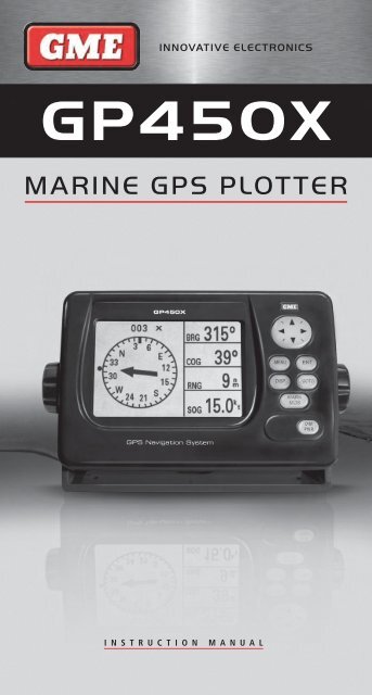
INNOVATIVE ELECTRONICS<br />
<strong>GP450X</strong><br />
MARINE GPS PLOTTER<br />
INstructIoN maNual
CAUTIONS . . . . . . . . . . . . . . . . . . . . . . . . . . . . . . . . . . . . 3<br />
Geodetic Chart System . . . . . . . . . . . . . . . . . . . . . . . . . 3<br />
TERMS . . . . . . . . . . . . . . . . . . . . . . . . . . . . . . . . . . . . . 3<br />
BRG (Bearing) . . . . . . . . . . . . . . . . . . . . . . . . . . . . . . . .3<br />
RNG (Range) The distance from your<br />
vessel to a destination or Waypoint . . . . . . . . . . . . . . . . 3<br />
SOG (Speed over Ground) . . . . . . . . . . . . . . . . . . . . . . .3<br />
COG (Course over Ground) . . . . . . . . . . . . . . . . . . . . . .3<br />
XTE (Cross track error) . . . . . . . . . . . . . . . . . . . . . . . . . 3<br />
ETA (Estimated time of arrival) . . . . . . . . . . . . . . . . . . . 3<br />
TTG (Time to go) . . . . . . . . . . . . . . . . . . . . . . . . . . . . . .3<br />
Waypoint . . . . . . . . . . . . . . . . . . . . . . . . . . . . . . . . . . . 3<br />
Route . . . . . . . . . . . . . . . . . . . . . . . . . . . . . . . . . . . . . .3<br />
MAINTeNANCe . . . . . . . . . . . . . . . . . . . . . . . . . . . . . . . . 3<br />
ACQUIRING GPS SIGNALS . . . . . . . . . . . . . . . . . . . . . . . .3<br />
Satellite Display Page . . . . . . . . . . . . . . . . . . . . . . . . . . 3<br />
CONTROLS . . . . . . . . . . . . . . . . . . . . . . . . . . . . . . . . . . . .4<br />
Using the Keypad . . . . . . . . . . . . . . . . . . . . . . . . . . . . . 4<br />
Cycling through the Displays (DISP) . . . . . . . . . . . . . . . .4<br />
Highway Display . . . . . . . . . . . . . . . . . . . . . . . . . . . . . .5<br />
Navigation Data Display . . . . . . . . . . . . . . . . . . . . . . . . 5<br />
Compass Display . . . . . . . . . . . . . . . . . . . . . . . . . . . . . .5<br />
Positional Navigation Data Display . . . . . . . . . . . . . . . . 6<br />
User Configurable Navigation Displays . . . . . . . . . . . . . 6<br />
Speedometer Display . . . . . . . . . . . . . . . . . . . . . . . . . . 6<br />
Controlling the Plotter Display . . . . . . . . . . . . . . . . . . . 6<br />
WAYPOINTS . . . . . . . . . . . . . . . . . . . . . . . . . . . . . . . . . . .7<br />
Entering a Waypoint from the<br />
Cursor Position . . . . . . . . . . . . . . . . . . . . . . . . . . . . . . 7<br />
Marking a Waypoint at the Vessels Position . . . . . . . . . .7<br />
Entering a Waypoint from the Waypoint List . . . . . . . . 7<br />
Editing Waypoint Attributes . . . . . . . . . . . . . . . . . . . 8<br />
Marking an MOB . . . . . . . . . . . . . . . . . . . . . . . . . . 8<br />
Nearest Waypoints . . . . . . . . . . . . . . . . . . . . . . . . . 9<br />
Proximity Waypoints . . . . . . . . . . . . . . . . . . . . . . . . 9<br />
Editing the Proximity Waypoint List . . . . . . . . . . . . . . . . 9<br />
Erasing Waypoints . . . . . . . . . . . . . . . . . . . . . . . . . . . .10<br />
ROUTeS . . . . . . . . . . . . . . . . . . . . . . . . . . . . . . . . . . . . . 10<br />
Creating Routes . . . . . . . . . . . . . . . . . . . . . . . . . . . . . 10<br />
Creating a Route using the Cursor . . . . . . . . . . . . . . . .10<br />
Creating a Route from the ROUTE Menu . . . . . . . . . . .11<br />
Creating Routes from the Waypoint List . . . . . . . . . . 11<br />
Creating a Track-based Route . . . . . . . . . . . . . . . . . . . 12<br />
Editing Routes . . . . . . . . . . . . . . . . . . . . . . . . . . . . . . 12<br />
coNtENts<br />
Erasing Routes . . . . . . . . . . . . . . . . . . . . . . . . . . . . 14<br />
SeTTING DeSTINATIONS . . . . . . . . . . . . . . . . . . . . . . 14<br />
Setting destinations by Cursor . . . . . . . . . . . . . . . . . 14<br />
Setting destinations by Waypoint . . . . . . . . . . . . . . . 14<br />
Setting destinations by Route . . . . . . . . . . . . . . . . . 15<br />
Setting destinations by MOB . . . . . . . . . . . . . . . . . . 15<br />
Setting User Waypoints as a Destination . . . . . . . . . 15<br />
Cancelling your Destination . . . . . . . . . . . . . . . . . . . 15<br />
ALARMS . . . . . . . . . . . . . . . . . . . . . . . . . . . . . . . . . . . 15<br />
Arrival and Anchor Watch Alarms . . . . . . . . . . . . . . 16<br />
Cross Track Error (XTE) Alarm . . . . . . . . . . . . . . . . . 16<br />
Speed Alarm . . . . . . . . . . . . . . . . . . . . . . . . . . . . . . 17<br />
Time Alarm . . . . . . . . . . . . . . . . . . . . . . . . . . . . . . . 17<br />
Trip Alarm . . . . . . . . . . . . . . . . . . . . . . . . . . . . . . . . 17<br />
Odometer Alarm . . . . . . . . . . . . . . . . . . . . . . . . . . . 17<br />
Buzzer Selection . . . . . . . . . . . . . . . . . . . . . . . . . . . 17<br />
OTheR NAvIGATION FUNCTIONS . . . . . . . . . . . . . . . 17<br />
Calculating Range, Bearing, TTG and ETA . . . . . . . . 17<br />
MAIN MeNU - CONFIGURING YOUR <strong>GP450X</strong> . . . . . . 18<br />
GPS Setup . . . . . . . . . . . . . . . . . . . . . . . . . . . . . . . 18<br />
Displaying the Message Board . . . . . . . . . . . . . . . . 19<br />
SYS Setup . . . . . . . . . . . . . . . . . . . . . . . . . . . . . . . . 20<br />
Plotter Setup . . . . . . . . . . . . . . . . . . . . . . . . . . . . . . 21<br />
Clearing Data . . . . . . . . . . . . . . . . . . . . . . . . . . . . . 23<br />
INSTALLATION . . . . . . . . . . . . . . . . . . . . . . . . . . .24<br />
Installing the Display Unit . . . . . . . . . . . . . . . . . .24<br />
Installation of Antenna Unit . . . . . . . . . . . . . . . . .24<br />
Grounding . . . . . . . . . . . . . . . . . . . . . . . . . . . . . . . 24<br />
CONNeCTING eXTeRNAL DevICeS . . . . . . . . . . . . . . 25<br />
Uploading and Downloading Waypoint<br />
& Route Data . . . . . . . . . . . . . . . . . . . . . . . . . . . . . 25<br />
Connecting to External Marine Devices . . . . . . . . . .25<br />
Selecting the NMEA Version . . . . . . . . . . . . . . . . .25<br />
Downloading Data to a PC . . . . . . . . . . . . . . . . . .25<br />
Uploading Data from a PC . . . . . . . . . . . . . . . . . . . 26<br />
Output data format, data sentences . . . . . . . . . . . .26<br />
Waypoint Data Format . . . . . . . . . . . . . . . . . . . . . . 27<br />
SPeCIFICATIONS . . . . . . . . . . . . . . . . . . . . . . . . . .28<br />
<strong>GP450X</strong> CUTTING TeMPLATe . . . . . . . . . . . . . . . . .29<br />
STATUTORY WARRANTIeS . . . . . . . . . . . . . . . . . . . . . 30<br />
PAGE 2 INSTRUCTION MANUAL <strong>GP450X</strong>
cautIoNs<br />
• The GPS system is operated and controlled by the U. S.<br />
Department of Defence (DOD) who is responsible for its<br />
maintenance and accuracy . The accuracy and reliability of all<br />
GPS equipment will be affected by any changes in the GPS<br />
system . Because of this, your <strong>GP450X</strong> should only be used as<br />
an aid to navigation and should not be relied on to precisely<br />
measure distance, direction or position .<br />
• To ensure safe navigation you should constantly compare<br />
information from your GPS against other navigation aids such<br />
as paper charts or visual sightings . If there are any variations<br />
you should resolve these before continuing . Chart Plotters<br />
are not a replacement for officially published mariner’s charts .<br />
Your <strong>GP450X</strong> should be used in conjunction with a range<br />
of navigation systems such as visual sightings, paper charts<br />
and depth soundings . Mariners should never rely on just one<br />
navigation tool .<br />
• Please thoroughly read this Instruction Manual before using<br />
your <strong>GP450X</strong> on your vessel . We recommend you practice<br />
with the Simulator mode before you begin real navigation on<br />
your vessel .<br />
• Do not open or disassemble your <strong>GP450X</strong> . Your unit should<br />
only be serviced by fully qualified personnel .<br />
• If the fuse blows, replace it with another fuse of the correct<br />
rating . Using an incorrect fuse could cause a fire or damage<br />
the unit beyond repair . If after replacing the fuse, it blows<br />
again, you should return your unit to an authorised service<br />
agent for repair .<br />
• Your <strong>GP450X</strong> is designed to operate from a power source of<br />
12 to 24 Volts DC . Operating the unit from voltages outside<br />
this range may damage the unit which is not covered<br />
by warranty .<br />
GEodEtIc chart systEm<br />
Your <strong>GP450X</strong> uses the WGS 84 chart datum . This is the<br />
standard datum used by GPS based charts worldwide . Some<br />
countries may have localised variations of the WGS 84 datum<br />
e .g . new charts in Australia may use the GDA 94 datum . The<br />
variation between GDA 94 and WGS 84 is so small it can’t be<br />
measured by your <strong>GP450X</strong> and the WGS 84 datum will provide<br />
the same positions .<br />
BrG (BEarING)<br />
tErms<br />
The direction from your vessel to a destination or Waypoint as<br />
measured by a compass .<br />
rNG (raNGE)<br />
The distance from your vessel to a destination or Waypoint .<br />
soG (sPEEd ovEr GrouNd)<br />
The speed of your vessel relative to the ground . GPS systems<br />
measure all speed referenced to the ground . This is different<br />
to your water speed as water currents can increase or decrease<br />
your ground speed .<br />
coG (coursE ovEr GrouNd)<br />
Also called a Track, it is the actual path followed by your vessel<br />
over the ground . This may be different to your heading as water<br />
currents and water movement can cause your real path to<br />
drift sideways .<br />
XtE (cross track Error)<br />
The distance that you are off to the left or right of an<br />
intended course .<br />
Eta (EstImatEd tImE of arrIval)<br />
The time you are expected to arrive at your destination .<br />
ttG (tImE to Go)<br />
The amount of time left before you arrive at your destination .<br />
WayPoINt<br />
A selected destination saved on your GPS unit .<br />
routE<br />
A set of Waypoints saved in a sequence that when activated will<br />
guide you to your destination along Waypoints .<br />
maINtENaNcE<br />
Regular maintenance is important to maintain performance .<br />
Check the following points regularly to help<br />
maintain performance .<br />
• Check that connectors on the rear panel are firmly tightened<br />
and free of corrosion .<br />
• Check that the ground system is free of corrosion and the<br />
ground wire is tightly fastened .<br />
• Check that battery terminals are clean and free<br />
of corrosion .<br />
• Check the antenna for damage. Replace if damaged.<br />
• Dust and dirt on the keyboard and display screen may be<br />
removed with a soft cloth . Do not use chemical cleaners to<br />
clean the equipment; they may remove paint and markings .<br />
• Use special care when cleaning the LCD Window – it is<br />
easily scratched .<br />
acQuIrING GPs sIGNals<br />
Before your unit can acquire a GPS position the antenna must<br />
be connected and be in full view of the sky . If the antenna’s<br />
view to the satellites is obscured by solid objects such as<br />
buildings or terrain or even parts of your vessel’s structure, it will<br />
not be able to receive signals from those satellites .<br />
When you first turn on your <strong>GP450X</strong>, it will need to download<br />
fresh data from the satellites . This data contains important<br />
information about the satellites that the GPS receiver requires in<br />
order to calculate positions . If your <strong>GP450X</strong> hasn’t been used<br />
recently or you have moved a long way from your last position,<br />
it may take a minute or so to download this data and acquire<br />
a position . This is known as a ‘Cold’ Fix . Once the data has<br />
been downloaded it is stored in the receiver and continuously<br />
updated while the receiver is on . This data remains valid for<br />
several hours after you turn the unit off, so that, if you turn the<br />
unit back on during this period it will use the stored data to reacquire<br />
your position much faster (‘Warm’ or ‘Hot’ fix) .<br />
Your <strong>GP450X</strong> requires at least 3 satellites to calculate a 2D<br />
position (latitude and longitude) and at least four satellites for a<br />
3D position (latitude and longitude and altitude) .<br />
satEllItE dIsPlay PaGE<br />
The satellite display page provides a sky view of the satellite<br />
positions along with their signal strengths . The satellite page is<br />
useful for checking the status of your GPS reception .<br />
The sky view consists of an outer ring marking the horizon and<br />
an inner ring marking a circle 45 °above the horizon . The dot<br />
in the centre represents a spot directly above your location and<br />
the top of the page faces north . The satellites are identified by<br />
numbers . The sky view assists in determining which satellites<br />
you are receiving and whether any satellites are being blocked<br />
by surrounding structures or terrain .<br />
The signal bars indicate the relative strength of the signals<br />
being received . Solid bars indicate the satellite is being used<br />
in the position fix . A shaded signal bar means the receiver<br />
is downloading data from the satellite . Once the data is<br />
<strong>GP450X</strong> INSTRUCTION MANUAL PAGE 3
downloaded that signal bar will become solid . A hollow bar<br />
indicates the receiver is not yet receiving a signal from that<br />
satellite (it may be blocked by obstacles) .<br />
To access the satellite display page select satEllItE<br />
from the main menu .<br />
Receiver Status North Dilution of Precision<br />
45<br />
DOP (value) .<br />
Bars show<br />
signal level .<br />
0 Elevation<br />
5 0 Elevation<br />
The following table shows the receiver status indicators that can<br />
be displayed in the top left of the satellite page .<br />
INdIcator mEaNING<br />
2D 2D GS position fix<br />
3D 3D GPS position fix<br />
S2D 2D SBAS GPS position fix<br />
S3D 3D SBAS GPS position fix<br />
SIM Simulator mode<br />
usING thE kEyPad<br />
coNtrols<br />
first Press: Screen Zoom range .<br />
Also escapes from<br />
current function .<br />
second Press: Accesses Main<br />
Menu options .<br />
Cycles through<br />
Navigation<br />
Display screens .<br />
Altitude<br />
turns unit on or off.<br />
Allows adjustment of<br />
screen contrast and<br />
backlight brilliance .<br />
Receiving /Using<br />
Signal .<br />
Downloading<br />
Data .<br />
Satellite numbers being used<br />
for positioning are highlighted<br />
on the display .<br />
cursor keypad: Adjusts cursor position<br />
on screen . Selects<br />
Menu items . Enters<br />
alphanumeric data .<br />
Accepts<br />
selected<br />
menu items .<br />
Selects or<br />
cancels a<br />
destination .<br />
short Press: Marks your current<br />
position as a waypoint .<br />
long Press: Marks your current<br />
potion as an MOB point .<br />
turNING thE uNIt oN aNd off (dIm/PWr)<br />
To turn the <strong>GP450X</strong> on, briefly press the dIm/PWr key . The<br />
unit will beep and turn on .<br />
To turn the <strong>GP450X</strong> off, press and hold the dIm/PWr key for 3<br />
seconds . The unit will count down then turn off .<br />
adJustING thE dIsPlay coNtrast aNd BacklIGht<br />
(dIm/PWr)<br />
To adjust the display brilliance and contrast, briefly press the<br />
dIm/PWr key .<br />
Press the or keys to adjust the Brilliance .<br />
Press the or keys to adjust the contrast .<br />
Press the ENt key to exit and save the new settings .<br />
mark/moB<br />
Briefly press the mark/moB key to save the current location<br />
as a Waypoint .<br />
Press and hold the mark/moB key to store your current<br />
location as an MOB (Man Over Board) Waypoint . You will be<br />
offered an option to immediately navigate back to the point .<br />
cyclING throuGh thE dIsPlays (dIsP)<br />
Briefly press the dIsP key to cycle through the available<br />
navigation screens. The <strong>GP450X</strong> has seven display modes –<br />
Plotter, Highway, Steering, Compass, Navigation Data, and<br />
two user configurable display options - Big Numbers<br />
and Speedometer .<br />
PAGE 4 INSTRUCTION MANUAL <strong>GP450X</strong>
Plotter display<br />
The plotter display shows your ships position, track history,<br />
bearing and range to target, course and speed over ground and<br />
zoom range .<br />
Bearing<br />
Waypoint<br />
Course over<br />
Ground<br />
Screen<br />
Range<br />
The Plotter page allows you to view your current location . It also<br />
displays a record of your track along with nearby Waypoints . The<br />
‘ship’ on the screen shows your present position and heading<br />
(the bow of the ship points in the direction of travel . At the<br />
corners of the screen are displayed the Bearing (BRG), Range<br />
(RNG), Course over Ground (COG) and Speed Over Ground<br />
(SOG) relative to your destination . Your present Latitude and<br />
Longitude is displayed at the bottom of the screen .<br />
If the unit is in ‘cursor’ mode, the Latitude and Longitude will<br />
display the position of the cursor on the screen and the BRG<br />
and RNG will display values relative to the cursor .<br />
hIGhWay dIsPlay<br />
The highway display provides a 3D view of your own vessel’s<br />
progress towards a destination (Waypoint), along with<br />
associated navigation data .<br />
Bearing<br />
from your<br />
vessel to<br />
destination<br />
waypoint .<br />
Course over<br />
Ground .<br />
Speed over<br />
ground .<br />
Ship’s Position when Navigating Cursor<br />
Position when Cursor is displayed .<br />
Direction you need to Steer to<br />
return to the correct course .<br />
Appears to the right or left of<br />
the centreline depending on<br />
steering direction required .<br />
Destination (cursor or waypoint name) .<br />
Range to<br />
Target<br />
Vessel<br />
Speed over<br />
Ground<br />
Destination<br />
Waypoint<br />
location . Moves<br />
forward as your<br />
vessel nears<br />
its destination .<br />
Boat Mark – displays course as follows:<br />
When waypoint is set, arrow shows<br />
boats course towards destination .<br />
When no waypoint is set, mode is North Up and<br />
arrow shows boats course towards destination .<br />
Analogue Cross Track Error (XTE) Scale .<br />
Arrow shifts with vessels XTE . When the<br />
arrow is aligned with the centreline, the<br />
boat is on course . Arrow blinks if vessel’s<br />
XTE is greater than the XTE scale . ‘N’<br />
(North) is displayed instead of arrow<br />
when no destination is set .<br />
Highway<br />
Range from your vessel to Destination waypoint .<br />
Digital XTE<br />
NavIGatIoN data dIsPlay<br />
The Navigation display provides a sliding compass scale . The<br />
vessel arrow in the centre shows your vessel’s present compass<br />
heading . The Waypoint Marker shows the direction of your<br />
destination Waypoint relative to your track .<br />
Bearing reference<br />
(Magnetic or True) .<br />
Receiver<br />
Status .<br />
Speed over<br />
Ground .<br />
Range from<br />
your vessel to<br />
destination . Time to Go (TTG)<br />
to destination .<br />
Note: The compass scale requires your vessel to be moving in<br />
order to determine your direction . It does not work while your<br />
vessel is stationary .<br />
The centre of the page features a sliding compass scale that<br />
shows your course over ground (current track) while you are<br />
moving . Your present course over ground is indicated by the<br />
vessel pointer in the centre of the display . A destination marker<br />
shows the Bearing to your destination Waypoint relative to your<br />
current track (COG) . The compass scale and Waypoint marker<br />
work independently to show at a glance the direction of your<br />
movement and direction to your destination .<br />
e .g . if the destination marker is to the left or right of your<br />
vessel’s current track you should steer towards the marker until<br />
it is directly above your vessel’s pointer . Once your vessel’s<br />
pointer is aligned with the destination marker, you are travelling<br />
towards your destination .<br />
comPass dIsPlay<br />
Course over<br />
Ground marker .<br />
Destination (CURSOR or<br />
Waypoint name) .<br />
Destination<br />
Marker .<br />
Time<br />
Compass<br />
Scale .<br />
Bearing<br />
Estimated Time of Arrival<br />
(ETA) at destination .<br />
Waypoint name Waypoint Symbol<br />
Compass Ring Bearing Pointer Bearing Marker<br />
When a destination is set the compass page will guide you to<br />
your destination with digital readouts and a graphic compass<br />
display which includes a bearing pointer . The Compass page is a<br />
good alternative to the highway page when travelling at slower<br />
speeds or when making frequent directional changes such as<br />
when straight line navigation is not possible due to obstructions<br />
or terrain .<br />
Note that the compass page requires your vessel to be moving<br />
in order to determine your direction . It does not work while your<br />
vessel is stationary .<br />
The centre of the page features a rotating compass that shows<br />
your course over ground (current track) while you are moving .<br />
Your present course over ground is indicated at the top of the<br />
compass ring . A Bearing Pointer in the centre of the compass<br />
<strong>GP450X</strong> INSTRUCTION MANUAL PAGE 5<br />
Vessel<br />
Course<br />
over<br />
Ground .<br />
Speed over<br />
Ground .<br />
Range from<br />
vessel to<br />
destination .<br />
Course over<br />
ground .<br />
Bearing to<br />
destination .
ing points to your destination Waypoint relative to your<br />
current track (COG) . The compass ring and Bearing Pointer<br />
work independently to show at a glance the direction of your<br />
movement and direction to your destination .<br />
e .g . if the Bearing Pointer points Up you are travelling directly<br />
towards your destination . If the Bearing Pointer points in any<br />
other direction you must turn towards the pointer until it points<br />
Up in order to continue towards your destination .<br />
PosItIoNal NavIGatIoN data dIsPlay<br />
Receiver Status<br />
Speed over<br />
ground .<br />
Date<br />
Course over<br />
Ground .<br />
The positional navigation data display provides GPS status,<br />
position in Latitude and Longitude, course over ground, speed<br />
over ground and the time and date . This page is useful for<br />
determining your current location for relaying to others or for<br />
simply confirming the current time or date .<br />
usEr coNfIGuraBlE NavIGatIoN dIsPlays<br />
The ‘Big Number’ Navigation display is used to show digital<br />
navigation information . It can be configured into 1, 2, 3 or 4<br />
separate fields on the screen as shown below .<br />
One Field Two Fields<br />
Three Fields Four Fields<br />
Time<br />
Position in Latitude<br />
and Longitude .<br />
There are two User Configurable Navigation displays that<br />
can be set either as ‘Big Number’ navigation fields or as an<br />
analogue Speedometer .<br />
Big Number Navigation display<br />
field 1<br />
field 2<br />
e .g . External Voltage<br />
e .g . Speed over Ground .<br />
field 3<br />
e .g . Trip Meter<br />
field 4<br />
e .g . Course over<br />
Ground .<br />
Each field can be individually configured to display<br />
• Time<br />
• Speed over Ground (SOG),<br />
• Cross Track error (XTE)<br />
• Odometer Distance<br />
• Position<br />
• Course over Ground (COG)<br />
• Time to Go (to Destination) (TTG)<br />
• Trip Distance<br />
• External Voltage (Volts)<br />
• Range and Bearing to Waypoint<br />
• Estimated time of Arrival (ETA)<br />
sPEEdomEtEr dIsPlay<br />
Speed Pointer Analogue Speed dial<br />
Digital Speed<br />
The Speedometer displays Speed over Ground . The display<br />
can be configured to suit the speed limitations of your vessel<br />
or the speed range of a specific application (such as trolling) .<br />
The Speedometer has 5 interval calibrations from minimum<br />
to maximum . Simply set the minimum speed and the interval<br />
speed and the Speedometer will be calibrated automatically .<br />
The example above shows the minimum speed set to 0 knots<br />
with the intervals set to 10 knots resulting in a Speedometer<br />
calibrated from 0 to 40 knots with 10 knot intervals .<br />
coNtrollING thE PlottEr dIsPlay<br />
display range<br />
You can select the display range (Zoom Level) on both the<br />
plotter and highway displays .<br />
On the plotter screen the horizontal display range is shown in<br />
the lower left corner of the display . The range of the plotter<br />
display can be set from 0 .02 to 320 display units . The display<br />
units can be preset to nautical miles, kilometres or statute miles .<br />
For maximum display range set the units to nautical miles to<br />
provide a maximum range of 320 nm .<br />
On the highway screen the zoom range can be set from 0 .2 to<br />
16 display units .<br />
selecting the display range<br />
With the plotter or highway window selected;<br />
1 . Press the mENu key . The Zoom, shIP to cENtrE menu<br />
appears and Zoom IN/out is highlighted .<br />
PAGE 6 INSTRUCTION MANUAL <strong>GP450X</strong>
Note: The shIP to cENtrE option only appears when the<br />
Plotter display was selected .<br />
2 . Press the ENt key to select the highlighted option . The Zoom<br />
control window appears .<br />
3 . Press to zoom out or to zoom in . The plotter or highway<br />
window changes automatically to represent the new<br />
range selection .<br />
4 . Press ENt to exit and return to the main display .<br />
moving the cursor<br />
Press the Cursor keypad to activate the cursor mode and move<br />
the cursor on the plotter display . The cursor moves in the<br />
direction of the keypad arrow . To move the cursor diagonally,<br />
press the keypad diagonally . To pan the entire screen beyond<br />
the currently visible display area, move the cursor beyond the<br />
edge of the display screen .<br />
cursor turned on<br />
When the Cursor mode is active the cursor ‘cross’ is displayed<br />
on the screen and the cursor position is displayed in latitude<br />
and longitude at the bottom of the display . The range and<br />
bearing from your vessel to the cursor is displayed in the upper<br />
corners of the display . You can use the Cursor mode to explore<br />
the plotter screen by panning the display or you can move the<br />
cursor to a specific position to store as a Waypoint or select as<br />
a destination .<br />
Note: When the Cursor mode is active, the display will<br />
remain at the cursor position . If your vessel is moving the<br />
vessel icon may move off the screen and be no longer<br />
visible . To re-locate the display to your vessel’s position see<br />
’centering your vessel’s Position’ further below .<br />
cursor turned off<br />
When the cursor is off the plotter displays your vessel on the<br />
screen and your vessel’s latitude and longitude at the bottom of<br />
the display . Navigation data is displayed at the screen’s corners .<br />
If the track function is turn on, a trail showing a record of your<br />
vessel’s movements is shown on the screen .<br />
centering your vessel’s Position.<br />
If your vessel is no longer visible on the screen, you can relocate<br />
the display to your vessels position as follows:<br />
1 . Press the mENu key,<br />
2 . Select shIP to cENtrE then press ENt .<br />
The Plotter screen will be restored with the vessel in the centre<br />
of the display .<br />
track recording<br />
Your <strong>GP450X</strong> can record a log of your vessel’s movements . Track<br />
points are stored in memory at regular intervals and displayed<br />
on the screen as a trail extending behind your vessel . The<br />
points are stored at distance intervals determined by settings<br />
in the Plotter Setup menu . A shorter interval allows more track<br />
points to be recorded which provides a more detailed log but<br />
uses more memory resulting in a shorter storage time . A longer<br />
interval will allow much longer recordings but there will be less<br />
detail . Once the track memory becomes full, the current track<br />
log will overwrite the oldest track points with newer points . If<br />
track recording is not required it can be turned off .<br />
WayPoINts<br />
In navigation terminology a Waypoint is a particular location<br />
on a voyage . It can be a start point, a destination or an<br />
intermediate location along the way . Your <strong>GP450X</strong> can store up<br />
to 999 Waypoints .<br />
Waypoints can be entered into your <strong>GP450X</strong> in one of<br />
three ways;<br />
• from the cursor position,<br />
• from your vessels own current position or<br />
• by manually entering a known latitude and longitude.<br />
ENtErING a WayPoINt from thE<br />
cursor PosItIoN<br />
On the Plotter display, use the cursor keypad to place the cursor<br />
at the location desired for the Waypoint . You can select the<br />
position by reading the latitude and longitude from the bottom<br />
of the screen or alternatively, create a position by moving the<br />
cursor to a point that is a specific distance and bearing from<br />
your vessel’s current location as indicated by the fields in the<br />
upper left and right of the display .<br />
With the cursor at the desired location, press the ENt key .<br />
The Waypoint entry window appears and a default numerical<br />
Waypoint name is displayed .<br />
Waypoint Name Entry Window<br />
1 . To accept the default Waypoint name simply press ENt .<br />
2 . To change the default Waypoint name, press the or<br />
keys to change the character at the cursor position . Press<br />
the or keys to move the cursor position left or right .<br />
The Waypoint name may consist of up to six alphanumerical<br />
characters . When the required name is displayed press the<br />
ENt key .<br />
The Waypoint attribute page appears showing the position,<br />
Waypoint symbol, time and date and arrival information for your<br />
new Waypoint . To accept the default fields press ENt.<br />
Waypoint attribute Window<br />
To edit the other Waypoint properties, see section on Editing<br />
Waypoint attributes on page 8 .<br />
markING a WayPoINt at thE vEssEls PosItIoN<br />
1 . To mark your vessels present location, briefly press the mark<br />
key . Your current location is automatically saved to memory<br />
with a default numerical Waypoint name and the Waypoint<br />
attribute page is displayed to allow you to edit the Waypoint’s<br />
properties if you wish . EXIt is highlighted .<br />
2 . To accept the default Waypoint name and attributes simply<br />
press ENt to finish .<br />
To edit the Waypoint properties, see section on Editing<br />
Waypoint attributes on page 8 .<br />
Default<br />
Waypoint<br />
Name .<br />
ENtErING a WayPoINt from thE WayPoINt lIst<br />
1 . Press the mENu key to access the main menu . Highlight<br />
the WayPoINts option and press ENt . The Waypoint list<br />
options are displayed .<br />
<strong>GP450X</strong> INSTRUCTION MANUAL PAGE 7
2 . Press ENt to select the lIst option . The Waypoints list<br />
page is displayed showing all of your Waypoints listed in<br />
alphabetical order . NEW is highlighted .<br />
NotE: There are three default systemgenerated<br />
waypoint names .<br />
3 . To create a new Waypoint, press ENt to select the NEW<br />
option . The Waypoint entry window appears and a default<br />
numerical Waypoint name is displayed .<br />
4 . To accept the default Waypoint name simply press ENt .<br />
5 . To change the default Waypoint name, press the or keys<br />
to change the character at the cursor position . Press the or<br />
keys to move the cursor position left or right . The Waypoint<br />
name may consist of up to six alphanumerical characters .<br />
When the required name is displayed press the ENt key .<br />
6 . The Waypoint attribute window appears showing the position,<br />
Waypoint symbol, time and date and arrival information for<br />
your new Waypoint . To accept the default fields and store the<br />
Waypoint press ENt.<br />
To edit the rest of the Waypoint properties, see section on<br />
‘Editing Waypoint attributes’ below .<br />
EdItING WayPoINt attrIButEs<br />
When creating a new Waypoint from the Cursor position, from<br />
your Vessel’s position or from the Waypoint List, the Waypoint<br />
Attribute page is displayed . This page is filled with default<br />
Waypoint information including the position, Waypoint symbol,<br />
time and date and arrival information for your new Waypoint .<br />
To accept the default fields and store the Waypoint press ENt,<br />
otherwise follow the steps below to edit the Waypoint attributes .<br />
Comment Field<br />
Waypoint List<br />
Waypoint Name entry Window<br />
FISH01<br />
TTG & ETA calculated according to<br />
TTG/ETAspeed in plotter setup .<br />
cursor: The last<br />
destination set<br />
using the cursor<br />
position .<br />
moB: The last<br />
Man Overboard<br />
position set by the<br />
MOB key .<br />
start: Your<br />
starting point<br />
when the last<br />
destination was<br />
selected .<br />
Waypoint Name<br />
Waypoint Symbol<br />
changing the Waypoint Name<br />
1 . Press the<br />
press ENt .<br />
or keys to highlight the Waypoint name and<br />
2 . Press the or keys to change the character at the cursor<br />
position and the or keys to move the cursor position left<br />
or right . Press ENt when done . The window below appears .<br />
CREATE?<br />
RENAME?<br />
3 . Press to highlight rENamE then press ENt . The original<br />
Waypoint name will be overwritten with the new name .<br />
changing the Waypoint symbol (mark)<br />
The Waypoint symbol appears on the plotter display to mark the<br />
location of your Waypoint . You can select from nine different<br />
Waypoint symbols to help categorise your Waypoints .<br />
1 . Press the or and or keys to highlight the currently<br />
displayed symbol (the default symbol is X . Press the ENt key .<br />
2 . Use the or keys to scroll through the list of symbols . The<br />
following symbols are available .<br />
3 . When the required symbol is displayed press the ENt key<br />
changing the comments field<br />
The Date and Time field can be replaced with a comment if<br />
required . A maximum of 16 characters is available .<br />
1 . Press the or keys to highlight the Date and Time field<br />
and press the ENt key .<br />
2 . Press the or keys to change the character at the cursor<br />
position and the or keys to move the cursor position<br />
left or right . To create a ‘space’, choose the ‘blank’ character .<br />
Press ENt when done .<br />
setting the log route function<br />
The Log Route function adds the Waypoint to the active route .<br />
For more details on this feature please refer to the<br />
routes section .<br />
markING aN moB<br />
The MOB mark denotes a ‘Man Overboard’ position . It allows<br />
you to instantly mark your current location in an emergency and<br />
quickly get navigation instructions back to it . The MOB location<br />
is stored in the Waypoint list as MOB . Only one MOB point can<br />
be stored . Each time you save a new MOB point the previous<br />
MOB is overwritten .<br />
1 . To save your current location as an MOB point press and<br />
hold the mark/moB key . The MOB point is saved and the<br />
following screen appears offering to navigate you back to the<br />
MOB point .<br />
Saving an MOB point<br />
2 . To navigate to the MOB point press the key to select<br />
yEs then press ENt . The plotter page will appear with the<br />
PAGE 8 INSTRUCTION MANUAL <strong>GP450X</strong>
MOB position shown as your destination and the required<br />
navigation data shown in the corners of the screen .<br />
Vessel<br />
Route to<br />
MOB<br />
Note: If you don’t wish to immediately navigate to the MOB<br />
point, simply press ENt to accept the No option . The point will<br />
remain in the Waypoint list in case you wish to navigate to it later .<br />
NEarEst WayPoINts<br />
The Nearest Waypoints list displays the Waypoints that are<br />
closest to your present location . It is useful for quickly finding<br />
nearby locations such as safe harbours, fuel, boat ramps or<br />
even fishing spots etc that you have previously stored in the<br />
Waypoint list .<br />
To view the nearest Waypoints, from the main menu, choose<br />
WayPoINts and press ENt . Select NEarEst from the list<br />
and press ENt . A Waypoint list is shown with the nearest<br />
Waypoints at the top of the list along with their range and<br />
bearing from your present location .<br />
To display the TTG (Time To Go) and ETA (Estimated Time of<br />
Arrival) to each Waypoint press the key .<br />
To return to the Waypoint by distance list press the key . Press<br />
the mENu key to close the Nearest list and return to the Menu .<br />
ProXImIty WayPoINts<br />
Bearing and Range to MOB point<br />
Plotter display with moB set as destination<br />
Waypoints listed by Nearest<br />
Waypoints listed by ttG and Eta<br />
MOB point<br />
A Proximity Waypoint is a Waypoint to which a proximity alarm<br />
has been applied . The alarm effectively places a ‘circle’ around<br />
that location . If you enter the area of the circle the alarm will<br />
trigger to warn you of your close proximity to that Waypoint .<br />
Proximity Waypoints are useful for warning of dangerous<br />
locations such as rocks, shallow water or other hazardous<br />
places . The Proximity Waypoint list in your <strong>GP450X</strong> can store up<br />
to 10 Proximity Waypoints .<br />
Your Vessel<br />
Vessel’s Course<br />
Alarm triggers here<br />
Proximity Waypoint<br />
1 . To access the Proximity Waypoint page, from the main menu,<br />
select WayPoINts and press ENt .<br />
2 . Select ProXImIty and press ENt . The Proximity Waypoint<br />
list is displayed .<br />
Proximity<br />
Waypoint<br />
Name .<br />
Active<br />
Proximity<br />
Alert .<br />
Range<br />
to active<br />
Proximity<br />
Waypoint .<br />
If you have not yet created any proximity Waypoints the list will<br />
be blank otherwise any Proximity Waypoints you have created<br />
will be listed . The Waypoint name is displayed on the left . On<br />
the right is the distance (circle radius) from the Waypoint at<br />
which the alarm will trigger .<br />
While viewing the Proximity Waypoint list, if a Proximity alarm<br />
is triggered, an exclamation mark will flash to the right of the<br />
affected Waypoint to identify it in the list . The range from your<br />
vessel to that Waypoint will also be displayed .<br />
3 . To add a Proximity Waypoint, use the or keys to<br />
highlight the first blank Waypoint position and press ENt . The<br />
standard Waypoint list is displayed .<br />
4 . Select the required Waypoint and press ENt . The screen<br />
returns to the Proximity Waypoint list . A default alarm<br />
distance is applied automatically .<br />
NotE: You must have first stored the required location as<br />
a Waypoint .<br />
5 . To change the distance at which the alarm will sound,<br />
highlight the Waypoint’s alarm distance and press ENt .<br />
6 . Use the or keys to change the number at the cursor<br />
position and the or keys to move the cursor position<br />
left or right .<br />
7 . Press ENt when done .<br />
Proximity Waypoint list<br />
EdItING thE ProXImIty WayPoINt lIst<br />
Proximity Alert Area<br />
Alarm Distance<br />
To edit the Proximity Waypoint list, highlight the Waypoint you<br />
wish to edit and press ENt .<br />
• Select rEvIEW to display or edit the standard properties of<br />
that Waypoint (such as location, symbol or comments etc) .<br />
• Select rEmovE to delete that specific Waypoint from the<br />
Proximity List . Note the Waypoint is only removed from<br />
the Proximity list, the original Waypoint still remains in the<br />
normal Waypoint list .<br />
• Select clEar all to delete ALL Waypoints from the<br />
Proximity list .<br />
Preset Alarm<br />
Distance .<br />
Indicates<br />
the Alarm<br />
has been<br />
triggered<br />
on this<br />
Waypoint .<br />
<strong>GP450X</strong> INSTRUCTION MANUAL PAGE 9
ErasING WayPoINts<br />
1 . At the main menu, highlight ErasE and press the ENt key .<br />
The Erase screen appears .<br />
2 . The WayPoINts/marks option is highlighted by default .<br />
Press the ENt key . The ERASE WPTS/MARKS screen is shown<br />
listing your current Waypoints .<br />
3 . To erase individual Waypoints, use the cursor keys to select<br />
the required Waypoint name then press ENt . The Waypoint<br />
properties window appears for the selected Waypoint .<br />
4 . Press the key to select the ErasE option and press ENt .<br />
The Waypoint is immediately erased .<br />
Note: You cannot erase system generated Waypoints such as<br />
CURSOR, MOB or START<br />
5 . To erase ALL the Waypoints in your unit, highlight the all?<br />
option and press ENt . You will be asked to confirm<br />
your selection .<br />
6 . Press the key to select yEs then press ENt . All your<br />
Waypoints will be deleted leaving just the system generated<br />
Waypoints cursor, moB and start .<br />
routEs<br />
Often a trip from one place to another involves several course<br />
changes requiring a series of Waypoints . This sequence of<br />
Waypoints leading you to your destination is called a route .<br />
Your <strong>GP450X</strong> can be programmed to traverse a sequence of<br />
Waypoints, automatically advancing to the next Waypoint as<br />
you progress, so you do not have to repeatedly switch to the<br />
next Waypoint . You can also travel the route in the opposite<br />
direction, using it to return back home again .<br />
crEatING routEs<br />
Example route along a river<br />
The <strong>GP450X</strong> can hold up to 50 stored routes plus one Route<br />
Log . Each route may contain up to 30 Waypoints . If you attempt<br />
to store more than 30 Waypoints a message will inform you that<br />
you can no longer save additional Waypoints to that route .<br />
A route may be constructed in one of four ways;<br />
• from the cursor<br />
• from the Waypoint list<br />
• from the route list or<br />
• storing your current position either automatically or manually.<br />
crEatING a routE usING thE cursor<br />
1 . With the plotter screen displayed, use the cursor keypad<br />
to place the cursor at the location of the first Waypoint<br />
(the latitude and longitude of the cursor is displayed at the<br />
bottom of the screen) .<br />
2 . Press the ENt key . The following window appears .<br />
The cursor will be on the second line ready to edit the<br />
Waypoint name if required . A default Waypoint name is<br />
offered which is the lowest Waypoint number currently<br />
available in your unit .<br />
3 . If you are happy to use the default Waypoint number<br />
supplied, simply press ENt to register the Waypoint under<br />
that number .<br />
If you prefer to change the Waypoint name then use the or<br />
keys to change the character at the cursor position and the<br />
or keys to move the cursor position left or right .<br />
The Waypoint name can have a maximum of 6 characters . Press<br />
ENt when done .<br />
The Waypoint attribute window is displayed .<br />
4 . If required, you can change the latitude and longitude<br />
and Waypoint Icon (Mark) . You can also replace the time<br />
and date with a comment (up to 16 characters) . Once any<br />
required changes are completed, select loG rtE and press<br />
the ENt key . This will store the Waypoint into the Route Log<br />
memory .<br />
PAGE 10 INSTRUCTION MANUAL <strong>GP450X</strong>
5 . Repeat the steps above to log additional Waypoints to the<br />
Route Log memory .<br />
6 . Once you have entered and logged all the required Waypoints<br />
for that route, press the mENu key twice to access the main<br />
menu . Select routEs and press the ENt key .<br />
7 . The routE menu will show the assembled route under the<br />
LOG heading . The route will be automatically labelled using<br />
the first and last Waypoints in the route .<br />
8 . To save the route, highlight the loG route (001 -> 003<br />
in the example above) and press the ENt key . The Route<br />
processing options are displayed .<br />
9 . Select movE and press the ENt key . The route will be<br />
moved from the Route Log memory to the first available<br />
sequential route number and the Route Log will listed<br />
as empty .<br />
Route Log<br />
LOGGED ROUTE 001 003<br />
route menu<br />
route Processing options<br />
If you wish to edit the route later on, follow the steps described<br />
under EdItING routEs later in this section .<br />
crEatING a routE from thE routE mENu<br />
The following process describes how to create a route using two<br />
Waypoints already stored in the Waypoint list . In this example<br />
the Waypoints are called ramP and fIsh1 .<br />
1 . From the main menu select routEs and press the ENt key .<br />
The Route list is displayed .<br />
route list<br />
2 . Select NEW and press the ENt key . The Route Entry screen<br />
appears (next column) .<br />
The route automatically uses the first available route number<br />
(Route 02 in the following example) . The first Waypoint<br />
position 01 is highlighted by default .<br />
route Entry Window<br />
3 . Press the ENt key . Use the or keys to scroll through the<br />
characters at the first cursor position . As you scroll through<br />
the characters your <strong>GP450X</strong> looks for stored Waypoints<br />
matching the characters you select and displays them . If<br />
more than one Waypoint exists with the same first letter (e .g .<br />
RAMP and RAMP2) use the or keys to move the cursor<br />
position left or right to select other letters that spell the name<br />
of the Waypoint you require .<br />
4 . When the required Waypoint name is displayed (RAMP in<br />
this example), press ENt . The next Waypoint position 02<br />
is highlighted . Repeat the steps above to select the next<br />
Waypoint (fIsh1 in this example) . Press ENt when done . You<br />
should now have two Waypoints stored in the route .<br />
5 . If you enter a Waypoint name that is not in the Waypoint list<br />
your <strong>GP450X</strong> screen will show the following message:<br />
Press to choose yEs then press the ENt to create a new<br />
Waypoint (or choose No to return to the Route entry screen) .<br />
6 . The Waypoint attribute edit window is displayed . Edit the<br />
latitude, longitude Icon (Mark) and comments as necessary<br />
then select EXIt and press ENt to return to the Route/<br />
entry screen .<br />
crEatING routEs from thE WayPoINt lIst<br />
This method is very similar to the method described for creating<br />
routes from the cursor .<br />
1 . From the main menu select WayPoINts and press the<br />
ENt key .<br />
2 . Choose lIst or NEarEst and press the ENt key .<br />
The Waypoint list is displayed .<br />
3 . Choose a Waypoint from the list and press the ENt key .<br />
The Waypoint attribute page is displayed .<br />
4 . Choose loG rtE and press the ENt key .<br />
5 . Repeats steps 3 and 4 to build the route .<br />
6 . When the route is completed press the mENu key once to<br />
return to the main menu then select routEs . The route you<br />
have assembled is stored under the loG heading .<br />
7 . Highlight the loG route and press the ENt key .<br />
<strong>GP450X</strong> INSTRUCTION MANUAL PAGE 11
8 . Select movE and press ENt . The route will be saved in the<br />
next available route memory and the LOG route will<br />
be cleared .<br />
9 . Press the mENu key twice to exit .<br />
crEatING a track-BasEd routE<br />
There are two methods by which you can create a track-based<br />
route; either by the manual input of track points using the<br />
MARK/MOB key or by the automatic inputting of track points<br />
from the ROUTES menu . A track-base route is very handy for<br />
retracing your track .<br />
manual method<br />
This method creates a route by storing a position each time the<br />
MARK/MOB key is pressed . Each time you alter your course,<br />
store a new position to mark that location . Your <strong>GP450X</strong> will<br />
create a route from these points that can be used for future<br />
navigation or as a route to follow when returning home .<br />
1 . Press the mark/moB key momentarily . The Waypoint<br />
attribute window is displayed .<br />
2 . Change the name, comment and Waypoint Icon (Mark) if<br />
desired, otherwise accept the defaults .<br />
3 . Select loG rtE and press the ENt key<br />
4 . Repeat steps 1 to 3 each time you change your heading so<br />
that another Waypoint is stored at that location . Up to 30<br />
positions can be saved into the route .<br />
5 . When you have entered all the positions you need, use the<br />
mENu key to access the main menu . Select routEs and<br />
press the ENt key .<br />
6 . Highlight the loG route and press the ENt key .<br />
7 . Select movE and press the ENt key . The route is moved and<br />
stored in the next available route memory .<br />
8 . Press the mENu key twice to exit .<br />
automatic method<br />
This method creates a route by automatically storing positions<br />
at intervals of time or distance . Up to 30 positions can be saved<br />
into the route<br />
1 . Use the mENu key to access the main menu .<br />
2 . Select routEs and press the ENt key .<br />
3 . Select INtErval and press the ENt key .<br />
4 . Select tImE or dIstaNcE as the method by which the<br />
position will be stored and press the ENt key .<br />
5 . Use the cursor keys to set the value for the time or distance<br />
interval and press the ENt key .<br />
For Example;<br />
To record a point every 15 minutes, set the interval to tImE and<br />
set the value to 00h 15m .<br />
To record a point every 2 km, set the interval to dIstaNcE and<br />
set the value to 02.0 km<br />
NotE: Since each route has a limit of 30 Waypoints, you should<br />
choose intervals that will extend the route to last the length of<br />
your trip . If you need to use smaller intervals you may need to<br />
save the points over several routes .<br />
6 . Select voyaGE routE and press the ENt key . Select<br />
start and press the ENt key .<br />
The <strong>GP450X</strong> will begin storing points according to your settings,<br />
starting with your current position . If you wish you can press<br />
mENu twice to return to your previous navigation screens . The<br />
<strong>GP450X</strong> will continue to log points in the background . Each<br />
time a new point is saved, ‘XXX savEd’ (where XXX is the<br />
Waypoint number) will be displayed at the top of the screen .<br />
When 30 Waypoints have been saved a message will inform you<br />
that you have reached the maximum number of Waypoints for<br />
your route and you can no longer save any more points . If this<br />
happens, press the ENt key to erase the message .<br />
To manually stop saving positions;<br />
1 . From the main menu select routEs.<br />
2 . Select voyaGE routE and press the ENt key .<br />
3 . Select stoP .<br />
The route is automatically saved under the loG route memory<br />
in the routEs menu .<br />
To store the route;<br />
1 . Use the mENu key to access the main menu .<br />
Select routEs and press the ENt key .<br />
2 . Highlight the loG route and press the ENt key .<br />
3 . Select movE and press the ENt key . The route is moved and<br />
stored in the next available route memory .<br />
4 . Press the mENu key twice to exit .<br />
EdItING routEs<br />
replacing Waypoints in a route<br />
To replace a Waypoint with another Waypoint from your<br />
Waypoint list:<br />
1 . Use the mENu key to access the main menu .<br />
2 . Select routEs and press the ENt key .<br />
3 . Select the route you wish to edit and press the ENt key .<br />
The route list is displayed .<br />
4 . Highlight the Waypoint you wish to replace and press the<br />
ENt key .<br />
5 . The route edit window appears .<br />
route menu Window<br />
6 . Select chaNGE and press the ENt key . The Waypoint<br />
attribute window appears .<br />
7 . Highlight the Waypoint name and press the ENt key . Use the<br />
cursor keys to select a new saved Waypoint name . Press the<br />
ENt key when done .<br />
PAGE 12 INSTRUCTION MANUAL <strong>GP450X</strong>
8 . Select EXIt and press the ENt key to return to the route<br />
list – or simply press the mENu key twice to return to your<br />
navigation screen .<br />
Note: When changing the Waypoint name, if you enter a name<br />
that doesn’t exist in your Waypoint list, you will be asked to<br />
either crEatE a new Waypoint or rENamE the<br />
current Waypoint .<br />
Permanently deleting a Waypoint from a route<br />
1 . Use the mENu key to access the main menu .<br />
2 . Select routEs and press the ENt key .<br />
3 . Select the route you wish to edit and press the ENt key .<br />
4 . Highlight the Waypoint you wish to delete and press the ENt<br />
key . The route edit window appears .<br />
CHANGE ?<br />
REMOVE ?<br />
route menu Window<br />
5 . Select rEmovE from the route edit menu and press the<br />
ENt key .<br />
6 . Press the mENu key twice to exit .<br />
Inserting a Waypoint into a route<br />
To insert a Waypoint into a route<br />
1 . From the main menu select routEs .<br />
2 . Select the desired route and press the ENt key .<br />
3 . Select the Waypoint that will come AFTER the Waypoint you<br />
are inserting and press the ENt key . For example, to insert<br />
a Waypoint between Waypoints ramP and 001 in the<br />
example below, select 001 and press ENt<br />
4 . The route edit window appears . Choose INsErt and press<br />
the ENt key .<br />
route menu Window<br />
4 . Use the cursor keypad to select the name of the Waypoint<br />
you wish to insert . For example to insert a Waypoint called<br />
markEr use the or keys to change the character at<br />
the cursor position to M . The Waypoint called markEr<br />
should appear .<br />
5 . Press the ENt key . The new Waypoint will be inserted into<br />
the route as shown below .<br />
6 . Press the mENu key twice to finish .<br />
temporarily skipping a Waypoint within a route<br />
If required, you can temporarily skip a Waypoint from within a<br />
route . In the example below Waypoint 002 has been skipped<br />
causing the route to bypass that Waypoint . The Waypoint<br />
remains in the route list but is not used in the route .<br />
Waypoint 002 is included in the route<br />
Waypoint 002 has been skipped<br />
To skip a Waypoint;<br />
1 . At the main menu select routEs and press the ENt key .<br />
2 . Select the desired route and press the ENt key .<br />
3 . Highlight the name of the Waypoint you wish to deselect and<br />
press the ENt key .<br />
4 . Select skIP from the Route Edit window and press the<br />
ENt key .<br />
5 . X appears to the left of the skipped Waypoint . The route will<br />
now bypass the skipped Waypoint .<br />
6 . Press mENu twice to return to the navigation screen .<br />
to restore the skipped Waypoint<br />
1 . Repeat the steps above and select skP off from the Route<br />
Edit Window at step 4, then press the ENt key .<br />
2 . The Waypoint is now restored and will be included in the<br />
route . Press mENu twice to exit .<br />
<strong>GP450X</strong> INSTRUCTION MANUAL PAGE 13
changing a route comment<br />
You can change the comment (name) of a route as follows . Up<br />
to 16 alphanumeric characters can be used .<br />
1 . From the main menu select routEs and press the ENt key .<br />
2 . Select the required route and press the ENt key .<br />
3 . Choose cmNt and press the ENt key .<br />
4 . Use the cursor keypad to enter the required comment<br />
(name) . Use the or keys to change the character at<br />
the cursor position and the or keys to move the cursor<br />
position left or right .<br />
5 . When the required comment has been entered press the<br />
ENt key .<br />
6 . Press mENu twice to return to the navigation screen .<br />
ErasING routEs<br />
To erase a route;<br />
1 . From the main menu select ErasE and press the ENt key .<br />
2 . Select routEs and press the ENt key .<br />
3 . Select the route you wish to erase and press the ENt key .<br />
NotE: If you want to erase all the route select all and press<br />
the ENt key<br />
4 . The ErasE routE option window appears . Select yEs and<br />
press the ENt key .<br />
5 . The select Route will be erased .<br />
6 . Press the mENu key twice to return to the<br />
navigation screen .<br />
sEttING dEstINatIoNs<br />
Destinations can be set in one of four ways;<br />
• by Cursor<br />
• by Waypoint<br />
• by Route<br />
• by MOB<br />
Use the Goto key to set a destination as shown below .<br />
sEttING dEstINatIoNs By cursor<br />
This method uses the location of the cursor as your destination .<br />
1 . Press the Goto key . The Goto option screen appears .<br />
2 . Select cursor? and press the ENt key . The plotter screen<br />
appears with a ? to the right of the cursor .<br />
3 . Use the cursor keypad to move the cursor to the desired<br />
location to be used for your destination .<br />
The destination can be determined either by reading the<br />
latitude and longitude from the bottom of the screen or as a<br />
Range and Bearing from your current location using the fields<br />
at the top corners of the screen .<br />
4 . Once the cursor is in the correct location press the ENt key .<br />
cursor is displayed at the cursor location and a dotted line<br />
connects your ships current position with the cursor position<br />
as shown below .<br />
sEttING dEstINatIoNs By WayPoINt<br />
This method uses a Waypoint from your Waypoint list as<br />
your destination .<br />
1 . Press the Goto key .<br />
2 . Select either WPt-lIst? or WPt-NEar and press the<br />
ENt key .<br />
NotE: WPT-LIST displays a list of all your Waypoints . WPT-NEAR<br />
displays the Waypoints closest to your present location .<br />
3 . Choose a Waypoint and press the ENt key<br />
4 . The plotter screen will appear with a dotted line extending<br />
from your ships position towards the selected Waypoint .<br />
Navigating to Waypoint<br />
NotE: If the selected Waypoint is not visible, its range may be<br />
beyond the selected zoom range of the screen and the dotted<br />
line will extend off the screen towards the Waypoint .<br />
sEttING dEstINatIoNs By routE<br />
1 . Press the Goto key<br />
destination set by cursor<br />
Navigating to Waypoint<br />
beyond zoom range<br />
2 . Select routE? and press the ENt key . The Route list<br />
is displayed .<br />
PAGE 14 INSTRUCTION MANUAL <strong>GP450X</strong>
oute list<br />
3 . Select a route from the list and press the ENt key . The Route<br />
Direction window appear .<br />
route direction Window<br />
4 . Choose forWard or rEvErsE to select the route<br />
direction . Choosing forWard will guide you along the<br />
route starting from the first Waypoint in the route and ending<br />
at the last . Choosing rEvErsE guides you back along<br />
the route in the opposite direction, starting from the last<br />
Waypoint and ending at the first . The rEvErsE option can<br />
be useful for finding your way back home at the end of<br />
the day .<br />
sEttING dEstINatIoNs By moB<br />
Normally when you save an MOB you are offered an option to<br />
immediately navigate to it . If you choose not to do so, you can<br />
use the GOTO function to call up the MOB later on .<br />
1 . Press Goto<br />
2 . Select WPt-lIst? and press the ENt key .<br />
2 . Choose the moB Waypoint and press the ENt key .<br />
3 . The plotter screen will appear with a dotted line extending<br />
from your ship’s position towards the moB point .<br />
sEttING usEr WayPoINts as a dEstINatIoN<br />
You can insert a User Waypoint into the Goto Options list . This<br />
allows you to quickly select a commonly used Waypoint<br />
for navigation .<br />
For example you could save the location of your local Boat<br />
Ramp as a Waypoint then insert this into the Goto Options<br />
list . This makes your boat ramp Waypoint easy to find when you<br />
need to navigate yourself back to the ramp at the end of<br />
the day .<br />
1 . Press Goto. The Goto options window appears .<br />
2 . Select sEtuP and press the ENt key . The Select User<br />
Waypoint list appears .<br />
3 . Select the desired Waypoint (ramP is selected in the<br />
example) and press the ENt key . The Goto window<br />
reappears and your selected Waypoint (ramP) is now listed<br />
as a Goto Waypoint .<br />
GOTO Options window with new User<br />
Waypoint (RAMP) inserted<br />
4 . Press mENu to exit and return to the navigation screens .<br />
To navigate to your user Waypoint at any time, simply press<br />
Goto, select your User Waypoint and press the ENt key . The<br />
plotter screen will appear with a dotted line extending from<br />
your vessel to the User Waypoint .<br />
caNcEllING your dEstINatIoN<br />
You can cancel your selected destination as follows;<br />
1 . Press the Goto key .<br />
2 . Select off? and press the ENt key .<br />
3 . The plotter screen will reappear and the selected Waypoint<br />
and dotted navigation line will no longer be visible .<br />
alarms<br />
Your <strong>GP450X</strong> has a number of alarm conditions that can<br />
generate both visual and audible alarms . The available<br />
alarms are;<br />
• Arrival Alarm<br />
• Anchor Watch Alarm<br />
• Cross Track Error (XTE) Alarm<br />
• Speed Alarm<br />
• Trip and Odometer Alarm<br />
• SBAS Alarm<br />
When an alarm is activated the buzzer sounds and the name<br />
of the offending alarm appears on the display along with an<br />
alarm Icon . To silence the buzzer and remove the visual alarm<br />
notification, simply press any key . The alarm Icon remains on the<br />
screen until the reason for the alarm is cleared .<br />
message Board<br />
In some instances, multiple alarms may be triggered . These<br />
alarm messages can be viewed on the Message Board .<br />
To view the message board;<br />
1 . From the main menu, select mEssaGEs and press the<br />
ENt key<br />
2 . Current messages will be listed .<br />
message Board<br />
New GOTO<br />
Waypoint<br />
Symbol<br />
For more information about the message board please refer to<br />
the maINtENaNcE section later in this manual .<br />
<strong>GP450X</strong> INSTRUCTION MANUAL PAGE 15
NotE: The arrival and anchor watch alarms cannot both be<br />
activated at the same time .<br />
arrIval aNd aNchor Watch alarms<br />
arrival alarm<br />
The arrival alarm alerts you when your vessel is approaching<br />
a destination Waypoint . The area that defines the arrival zone<br />
is a circle surrounding the destination Waypoint . The alarm is<br />
triggered when your vessel enters the circle .<br />
setting the arrival alarm<br />
arrival alarm<br />
1 . From the main menu select alarms and press the ENt key<br />
2 . Select the arv/aNc field and press the ENt key .<br />
3 . The Arrival/Anchor Options list appears .<br />
4 . Select arv and press the ENt key .<br />
5 . The Alarm Range field is automatically highlighted . Press the<br />
ENt key .<br />
6 . Use the Cursor keypad to enter the alarm range . Use the<br />
or keys to change the number at the cursor position and<br />
the or keys to move the cursor position left or right .<br />
When finished press the ENt key .<br />
7 . Press mENu twice to exit and return to the<br />
navigation screen .<br />
When your vessel approaches a destination Waypoint at the<br />
range set here the buzzer sounds and the message arv<br />
alarm! is displayed .<br />
anchor Watch alarm<br />
The Anchor Watch alarm warns you that your anchored vessel is<br />
moving excessively when it should be at rest . It works similarly<br />
to the arrival alarm except that it alerts you when your vessel<br />
leaves a circle rather than enters it . When setting the alarm<br />
you should allow for the possible distance your vessel may<br />
legitimately drift while at anchor . The alarm distance should<br />
be set to warn if the anchor is dragging and your position is<br />
moving excessively .<br />
setting the anchor Watch alarm<br />
1 . From the main menu select alarms and press the ENt key<br />
2 . Select the arv/aNc field and press the ENt key .<br />
3 . The Arrival/Anchor Options list appears .<br />
4 . Select aNc and press the ENt key .<br />
5 . The Alarm Range field is automatically highlighted . Press the<br />
ENt key .<br />
6 . Use the Cursor keypad to enter the alarm range . Use the<br />
or keys to change the number at the cursor position and<br />
the or keys to move the cursor position left or right .<br />
When finished press the ENt key .<br />
7 . Press mENu twice to exit and return to the<br />
navigation screen .<br />
When your vessel drifts beyond the range set here the buzzer<br />
sounds and the message aNc alarm! is displayed .<br />
cross track Error (XtE) alarm<br />
The XTE error occurs when your ship strays from its intended<br />
course . The XTE is useful when navigating through narrow<br />
channels or as a simple warning in case you are distracted<br />
while navigating .<br />
setting the XtE alarm<br />
anchor alarm<br />
XtE Error alarm<br />
1 . From the main menu select alarms and press the ENt key<br />
2 . Select the XtE field and press the ENt key .<br />
3 . The XtE Options list appears . Select oN and press the<br />
ENt key .<br />
4 . The Alarm Range field is automatically highlighted . Press the<br />
ENt key .<br />
PAGE 16 INSTRUCTION MANUAL <strong>GP450X</strong>
5 . Use the Cursor keypad to enter the alarm range . Use the<br />
or keys to change the number at the cursor position and<br />
the or keys to move the cursor position left or right .<br />
When finished press the ENt key .<br />
6 . Press mENu twice to exit and return to the<br />
navigation screen .<br />
When your vessel strays from its intended course by the distance<br />
set here, the buzzer will sound and the message XtE alarm!<br />
will be displayed .<br />
sPEEd alarm<br />
The speed alarm provides visual and audible alerts when the<br />
ship’s speed is higher or lower than the alarm range setting .<br />
setting the speed alarm<br />
1 . From the main menu select alarms and press the ENt key .<br />
2 . Select sPEEd and press the ENt key . The Speed Options<br />
menu appears .<br />
3 . Choose loW or hIGh and press the ENt key .<br />
- The loW settings sounds an alarm when the speed falls<br />
below the Speed Alarm setting<br />
- The hIGh setting sounds an alarm when the speed exceeds<br />
the Speed Alarm setting .<br />
4 . The Speed Range field is automatically highlighted . Press the<br />
ENt key .<br />
5 . Use the Cursor keypad to enter the alarm speed . Use the<br />
or keys to change the number at the cursor position and<br />
the or keys to move the cursor position left or right .<br />
When finished press the ENt key .<br />
6 . Press mENu twice to exit and return to the<br />
navigation screen .<br />
When your vessel violates the speed alarm setting the buzzer<br />
sounds and the message sPd alarm! is displayed .<br />
tImE alarm<br />
The time alarm works as an alarm clock to provide a visual and<br />
audible alert at the set time .<br />
setting the time alarm<br />
1 . From the main menu select alarms and press the ENt key .<br />
2 . Select the tImE field and press the ENt key<br />
3 . Select oN and press the ENt key .<br />
4 . The Time setting field is automatically highlighted . Press the<br />
ENt key .<br />
5 . Use the Cursor keypad to enter the alarm time . Use the or<br />
keys to change the number at the cursor position and the<br />
or keys to move the cursor position left or right . When<br />
finished press the ENt key .<br />
6 . The am/Pm indicator is automatically highlighted . Press the<br />
ENt key .<br />
7 . Select am or Pm and press the ENt key .<br />
8 . Press mENu twice to exit and return to the<br />
navigation screen .<br />
When the preset time is reached the buzzer sounds and the<br />
message tImE alarm! is displayed .<br />
trIP alarm<br />
The Trip Alarm is triggered when the distance travelled by your<br />
vessel exceeds the distance preset in the Trip Alarm .<br />
setting the trip alarm<br />
1 . From the main menu select alarms and press the ENt key .<br />
2 . Select the trIP field and press the ENt key<br />
3 . Select oN and press the ENt key .<br />
4 . The Trip Distance field is automatically highlighted . Press the<br />
ENt key .<br />
5 . Use the Cursor keypad to enter the trip distance . Use the<br />
or keys to change the number at the cursor position and<br />
the or keys to move the cursor position left or right .<br />
When finished press the ENt key .<br />
6 . Press mENu twice to exit and return to the<br />
navigation screen .<br />
When the distance that your vessel has travelled exceeds the<br />
preset distance, the buzzer sounds and the message trIP<br />
alarm! is displayed .<br />
odomEtEr alarm<br />
The Odometer Alarm is similar to the trip alarm . Whereas<br />
the Trip Alarm can be reset regularly to monitor short trips<br />
the Odometer Alarm can be left to accumulate much larger<br />
distances over multiple trips .<br />
setting the odometer alarm<br />
1 . From the main menu select alarms and press the ENt key .<br />
2 . Select the odomEtEr field and press the ENt key<br />
3 . Select oN and press the ENt key .<br />
4 . The Odometer Distance field is automatically highlighted .<br />
Press the ENt key .<br />
5 . Use the Cursor keypad to enter the odometer distance . Use<br />
the or keys to change the number at the cursor position<br />
and the or keys to move the cursor position left or<br />
right . When finished press the ENt key .<br />
6 . Press mENu twice to exit and return to the<br />
navigation screen .<br />
When your vessel has travelled further than the preset odometer<br />
distance the buzzer sounds and the message odomEtEr<br />
alarm! is displayed .<br />
BuZZEr sElEctIoN<br />
The buzzer sounds whenever an alarm is activated . You can<br />
choose the buzzer parameters as follows;<br />
1 . From the main menu select alarms and press the ENt key .<br />
2 . Select BuZZEr and press the ENt key . The Buzzer Options<br />
menu appears .<br />
3 . Choose from short, loNG or coNstaNt .<br />
- short provides three short beeps then stops .<br />
- loNG provides three long beeps then stops .<br />
- coNstaNt will beep continuously until cancelled by<br />
pressing any key .<br />
4 . Press mENu twice to exit and return to the<br />
navigation screen .<br />
othEr NavIGatIoN fuNctIoNs<br />
calculatING raNGE, BEarING, ttG aNd Eta<br />
range and Bearing between two Waypoints<br />
1 . From the main menu select calculatE and press the ENt<br />
key . The calculation window is displayed .<br />
2 . The modE option is highlighted by default . Press the ENt<br />
key to select .<br />
3 . The Mode Option menu appears . Choose WayPoINts and<br />
press the ENt key .<br />
<strong>GP450X</strong> INSTRUCTION MANUAL PAGE 17
4 . The from field is highlighted . Press the ENt key .<br />
5 . Use the Cursor keypad to select the first Waypoint from the<br />
Waypoint list . Press the ENt key when done .<br />
6 . Highlight the to field and press the ENt key .<br />
7 . Use the Cursor keypad to select the second Waypoint from<br />
the Waypoint list . Press the ENt key when done .<br />
8 . Highlight the sPd field and press the ENt key .<br />
9 . Choose auto or maN (Manual) and press the ENt key .<br />
- auto uses your vessel’s average speed .<br />
- maN uses a speed that you choose .<br />
10 . If auto was selected the ttG, Eta, Range and BrG are<br />
automatically displayed at the bottom of the screen . These<br />
values are calculated using your vessel’s average speed .<br />
Time to Go<br />
Range<br />
11 . If maN was selected a speed field appears .<br />
12 . Press the ENt key to access the sPEEd field . Use the<br />
Cursor keypad to select the required speed value . Press the<br />
ENt key when done .<br />
13 . The ttG, Eta, Range and BrG are displayed at the bottom<br />
of the screen . These values are calculated using the speed<br />
value you entered above .<br />
14 . Press the mENu key twice to return to the<br />
navigation screen .<br />
range, ttG and Eta of a route<br />
Estimated Time of Arrival<br />
Bearing<br />
This function calculates the Range, TTG and ETA between the<br />
first and last Waypoints of a route .<br />
1 . From the main menu select calculatE and press the ENt<br />
key . The calculation window is displayed<br />
2 . The modE field is highlighted by default . Press the ENt key<br />
to select .<br />
3 . The Mode Option menu appears . Choose routE and press<br />
the ENt key .<br />
4 . Highlight the Route Number (default is 01) and press the<br />
ENt key .<br />
5 . Use the Cursor keypad to select the required Route number<br />
then press the ENt key . The names of the Start and<br />
Destination Waypoints of the selected route are displayed<br />
along with the number of Waypoints in the route .<br />
6 . Highlight the sPd field and press the ENt key .<br />
7 . Choose auto or maN (Manual) and press the ENt key .<br />
- auto uses your vessel’s average speed .<br />
- maN uses a speed that you choose .<br />
8 . If auto was selected the ttG, Eta and Range are<br />
automatically displayed at the bottom of the screen . These<br />
values are calculated using your vessel’s average speed .<br />
Time to Go<br />
9 . If maN was selected a speed field appears .<br />
10 . Press the ENt key to access the sPEEd field . Use the<br />
Cursor keypad to select the required speed value . Press the<br />
ENt key when done .<br />
11 . The ttG, Eta and Range are displayed at the bottom of the<br />
screen . These values are calculated using the speed value<br />
you entered above .<br />
12 . Press the mENu key twice to return to the<br />
navigation screen .<br />
GPs sEtuP<br />
Estimated Time of Arrival<br />
maIN mENu - coNfIGurING<br />
your <strong>GP450X</strong><br />
The GPS Setup menu smoothes position and course, averages<br />
speed, applies position offsets and deactivates unhealthy<br />
satellites .<br />
Position smoothing<br />
If the GPS satellite signal condition becomes temporarily<br />
unfavourable, the accuracy of the GPS position can be affected<br />
to the point where your position on the plotter may appear to<br />
move around even though your vessel is not moving . This effect<br />
can be reduced by smoothing the raw GPS measurements so<br />
that their effect on your navigation is minimised . The setting<br />
range is from 0 to 999 seconds . The higher settings provide<br />
more smoothing but will slow the time that the unit responds<br />
to valid changes in position, especially at higher speeds . The<br />
default setting is 0 seconds . Increase this setting if the GPS<br />
position fix is changing greatly when you are not moving .<br />
speed and course smoothing<br />
As with your position, your vessel’s speed and course is directly<br />
measured using the GPS satellite signals . This means the raw<br />
velocity data will be affected by unfavourable satellite signal<br />
PAGE 18 INSTRUCTION MANUAL <strong>GP450X</strong><br />
Range<br />
No of<br />
Waypoints<br />
in the Route<br />
Start and<br />
Destination<br />
Waypoints
conditions . You can reduce these affects by increasing the Speed<br />
and Course smoothing . As with position smoothing, the higher<br />
the value you select for Speed and Course Smoothing the more<br />
smoothed will be the raw data . If the setting is too high the<br />
response to speed and course changes will become slower . The<br />
setting range is from 0 to 9999 seconds .<br />
average speed (speed averaging)<br />
Speed averaging over a period of time is useful for calculating<br />
ETA (Estimated Time of Arrival) and TTG (Time to Go) . If the<br />
averaging period is too long or too short, the accuracy of the<br />
ETA and TTG calculations will be affected . The default setting is<br />
60 seconds . The available setting range is 0 to 9999 seconds .<br />
lat/loNG offset<br />
The Latitude and Longitude Offset can be used to adjust<br />
position accuracy . It is especially useful when you are<br />
referencing to a paper chart that is not using the same WGS<br />
84 datum as your <strong>GP450X</strong> . This could result in the positions<br />
measured on your <strong>GP450X</strong> not matching those on the paper<br />
chart . By applying a position offset to your <strong>GP450X</strong> you can<br />
calibrate the measured positions on your <strong>GP450X</strong> to match<br />
those on the paper chart .<br />
disable sv (satellite visibility)<br />
The Disable SV option allows you to deselect satellites that<br />
you do NOT wish to use in position calculations . This might be<br />
because they have been reported as unhealthy and therefore<br />
unreliable or perhaps because their visibility is poor resulting in<br />
inconsistent position accuracy . Up to three satellites can<br />
be disabled .<br />
fix mode<br />
The fix mode allows you to select either 2 dimensional (latitude<br />
and longitude) or 3 dimensional (latitude, longitude and<br />
altitude) fixes . If 2/3D is selected your <strong>GP450X</strong> will provide<br />
fixes in 3 dimensions where satellite visibility is good . Where<br />
satellite visibility is poor your unit will automatically switch to<br />
2D fix mode until the signal improves, with a reduced positional<br />
accuracy . To improve positional accuracy in these situations you<br />
can manually select the 2D fix mode . You will then be asked<br />
to enter the altitude to be used in the calculation, to make the<br />
position more accurate .<br />
To apply these settings;<br />
1 . From the main menu select GPs sEtuP and press the<br />
ENt key .<br />
2 . Select the smooth Pos field and press the ENt key .<br />
3 . Use the cursor keys to enter a speed smoothing value from<br />
000 to 999 seconds . For example, if you select 3 seconds,<br />
your position measurement will be smoothed over a three<br />
second period . Press ENt when complete .<br />
4 . The smooth sc field is highlighted . Press the ENt key .<br />
5 . Use the cursor keys to enter a Course smoothing value from<br />
0000 to 9999 seconds . Press ENt when complete .<br />
NotE: For long trips you may prefer to use larger values . For<br />
shorter trips or when regular direction changes are needed<br />
you should use smaller values . To disable Position or Course<br />
smoothing, set these values to 0 .<br />
6 . The avr sPEEd field is highlighted . Press the ENt key .<br />
7 . Use the cursor keys to enter the period over which your<br />
speed will be averaged . For example, if you select 60<br />
seconds, your speed will be averaged over a 1 minute period .<br />
Press ENt when complete .<br />
8 . The lat offsEt field is highlighted . Press the ENt key .<br />
9 . Use the cursor keys to enter the Latitude offset in minutes<br />
and decimal minutes and to select N (North) or s (South) .<br />
The default is 0.000. When finished press the ENt key .<br />
10 . The loN offsEt field is highlighted . Press the ENt key .<br />
11 . Use the cursor keys to enter the Longitude offset in minutes<br />
and decimal minutes and to select E (East) or W (West) .<br />
The default is 0.000. When finished press the ENt key .<br />
12 . The dIaBlE sv field is highlighted . Press the ENt key .<br />
13 . Use the cursor keys to select the satellite number you wish<br />
to disable . Press the ENt key when done . To disable more<br />
than one satellite press the key to move the cursor to the<br />
right and press the ENt key to select the next satellite field .<br />
Up to three satellites can be disabled .<br />
NotE: To restore disabled satellites, set the satellite number<br />
to 00 .<br />
14 . The fIX modE field is highlighted . Press the ENt key .<br />
15 . Select from 2d or 2/3d and press the ENt key .<br />
If 2d mode is selected you will be asked to enter a default<br />
altitude . Use the cursor keys to enter an altitude and press the<br />
ENt key . If you are at sea you can set an altitude of 0 .<br />
dIsPlayING thE mEssaGE Board<br />
The message board displays error messages and alerts . You can<br />
display it as follows:<br />
From the main menu select mEssaGEs and press the ENt key .<br />
The Message Board will be displayed along with any messages .<br />
The following messages are available .<br />
message meaning<br />
ANCHOR WATCH! Anchor watch alarm triggered .<br />
ARRIVAL ALARM! Arrival alarm triggered .<br />
BACKUP ERROR<br />
DATA!<br />
Message Board<br />
RAM data corrupted . Try to clear<br />
backup data .<br />
BATTERY ALARM! Voltage of battery in display unit is<br />
low . Request replacement .<br />
GPS NO FIX! No GPS signal . Check antenna cable<br />
HIGH VOLTAGE! Power source voltage too high .<br />
LOW VOLTAGE! Power source voltage too low .<br />
ODOMETER<br />
ALARM!<br />
Odometer distance alarm triggered .<br />
RAM ERROR! Return for service .<br />
ROM ERROR! Return for service .<br />
RTC ERROR! Return for service .<br />
SPEED ALARM! Speed alarm triggered .<br />
TIME ALARM! Time alarm triggered .<br />
TRIP ALARM! Trip distance alarm triggered .<br />
XTE ALARM! Cross Track Error alarm triggered .<br />
<strong>GP450X</strong> INSTRUCTION MANUAL PAGE 19
sys sEtuP<br />
language<br />
Your <strong>GP450X</strong> supports the following languages;<br />
• English<br />
• French<br />
• Spanish<br />
• Italian<br />
• Chinese<br />
To change the language setting;<br />
1 . From the main menu, select sys sEtuP and then press the<br />
ENt key .<br />
2 . Select the laNGuaGE field and press the ENt key .<br />
3 . Use the or keys to select the required language then<br />
press the ENt key .<br />
4 . Press the mENu key twice to return to the<br />
navigation screen .<br />
units of measurement<br />
Distance and Speed can be displayed in Nautical Miles/Knots,<br />
kilometres/kilometres per hour or statute miles/miles per hour .<br />
to change the settings<br />
1 . From the main menu select sys sEtuP and press the<br />
ENt key .<br />
2 . Select the uNIts field and press the ENt key .<br />
3 . Choose the distance/speed combination required and press<br />
the ENt key .<br />
4 . Press the mENu key twice to return to the<br />
navigation screen .<br />
time difference (local time), time format<br />
The GPS system uses the international time standard UTC<br />
based at Greenwich in England . To display local time you need<br />
to apply a time offset to the GPS time . Your <strong>GP450X</strong> can also<br />
display time in 12 or 24 hour format .<br />
to set local time<br />
1 . From the main menu select sys sEtuP and press the<br />
ENt key<br />
2 . Select the tImE dIff field and press the ENt key .<br />
3 . Press the or keys to change the first character to + or – .<br />
4 . Press the key to move the cursor to the right . Use the<br />
or keys to change the value of the time offset to suit your<br />
local area .<br />
e.g. for sydney the offset would be set to + 10:00.<br />
NotE: During Daylight Savings time add 1 hour to the normal<br />
time offset .<br />
5 . When finished press the ENt key .<br />
6 . The tImE dIsP is highlighted . Press the ENt key .<br />
7 . Choose 12 hour or 24 hour and press the ENt key .<br />
8 . Press the mENu key twice to return to the navigation screen<br />
simulator<br />
To practice with your <strong>GP450X</strong> you can select the Simulator<br />
mode . This mode provides a simulated operation allowing the<br />
unit to function as if it were calculating positions and moving<br />
around . All controls will operate normally and you can create<br />
Waypoints and follow routes to their destinations .<br />
1 . From the main menu select sys sEtuP and press the<br />
ENt key<br />
2 . Select sImulator and press the ENt key .<br />
3 . Select the modE field and press the ENt key .<br />
4 . Choose oN and press the ENt key . The simulation mode is<br />
now active .<br />
5 . Select the sPEEd field and press the ENt key<br />
6 . Use the cursor keys to enter a speed that you would like the<br />
unit to simulate while following routes . Press the ENt key<br />
when done .<br />
7 . Select the coursE field and press the ENt key .<br />
8 . Choose auto or maN and press the ENt key .<br />
To automatically simulate routes to chosen destinations you<br />
should select auto .<br />
9 . Select lat and press the ENt key .<br />
10 . Use the cursor keys to enter the latitude of your simulation<br />
starting position and press the ENt key .<br />
11 . Select loN and press the ENt key .<br />
12 . Use the cursor keys to enter the longitude of your simulation<br />
starting position and press the ENt key .<br />
13 . Press the mENu key twice to return to the<br />
navigation screen .<br />
Press the dIsP key repeatedly until the Plotter screen is<br />
displayed . sIm appears in the upper left of the display when the<br />
simulator is active .<br />
To turn off the simulator, set the simulator modE in step 3<br />
to off .<br />
Note the simulator mode will be also be turned off<br />
automatically when the unit is switched off .<br />
diagnostics<br />
The diagnostic test checks rom, ram, data port, beacon<br />
receiver, battery, rtc, keyboard and lcd for proper operation .<br />
1 . From the main menu select sys sEtuP and press the<br />
ENt key .<br />
2 . Choose tEst and press the ENt key . You will be asked if you<br />
are ready to start the test .<br />
3 . Select yEs and press the ENt key to start the test .<br />
Turns Simulator<br />
ON or OFF .<br />
Sets Simulation<br />
Speed .<br />
Sets Simulation<br />
Starting Position .<br />
PAGE 20 INSTRUCTION MANUAL <strong>GP450X</strong>
4 . The <strong>GP450X</strong> tests rom, ram, data port, beacon receiver,<br />
internal battery and rtc . The results are individually<br />
displayed as ok or NG (No Good) .<br />
5 . After the equipment has displayed the test results, a beep<br />
sounds and the message Push kEy appears at the top<br />
right-hand corner .<br />
6 . Press each key one by one . The name of the key pressed<br />
momentarily appears at the top right-hand corner if the key<br />
is functioning properly .<br />
If no key is pressed within around 5 seconds, the <strong>GP450X</strong><br />
automatically proceeds to the next stage .<br />
7 . The equipment displays the following message to inform you<br />
that it is now going to check the lcd .<br />
8 . The lcd is checked and the test is then repeated .<br />
9 . To stop the test, turn off the power .<br />
Note 1: DATA2 requires a special connector to check.<br />
- - appears as the result when no connector is connected .<br />
Note 2: CNT shows the number of times the test has been<br />
executed consecutively .<br />
PlottEr sEtuP<br />
track recording<br />
To record a copy of the ships track, the ships position is stored<br />
in memory at regular intervals of distance . A shorter distance<br />
interval provides more track points and a more detailed log<br />
of your track but more memory is used resulting in a shorter<br />
storage time . When the track memory becomes full, the older<br />
track points are overwritten by the newer points .<br />
To change the setting press the or keys to highlight the<br />
‘track rEc’ option and press ENt .<br />
Select Distance to define your<br />
own fixed value for the track<br />
log interval . The distance interval<br />
will remain constant at all<br />
zoom ranges .<br />
Select Auto to let the <strong>GP450X</strong> define the track log recording<br />
interval automaticaly . The interval will change with the zoom<br />
range setting .<br />
Select off to disable the track logging function altogether .<br />
Interval<br />
Sets the distance interval for when Distance is selected in the<br />
Track Recording option above . When the Track Recording option<br />
is set to off or auto this setting is not available .<br />
To set the interval press the or keys to highlight the<br />
‘INtErval’ option and press ENt . Use the keys to<br />
change the value and the keys to move left or right<br />
through the fields .<br />
Bearing reference<br />
Your vessel’s course and bearing to a destination may be<br />
displayed in either True or Magnetic formats . A True bearing is<br />
one referenced to the earth’s geographic North Pole . A Magnetic<br />
bearing is referenced to the magnetic north pole which is offset<br />
from true north . This magnetic variation changes according<br />
to your location . The magnetic bearing is identical to that<br />
measured by a standard magnetic compass .<br />
It is recommended you select the bearing reference that<br />
matches other navigation equipment in your vessel . Select<br />
Magnetic to match a magnetic compass or True if you use a<br />
gyrocompass . The default setting is Magnetic .<br />
To change the setting<br />
1 . From the main menu select PlottEr and press the ENt key .<br />
2 . Select the BrG rEf field and press the ENt key .<br />
Plotter setup menu<br />
3 . Choose maG or truE as required and press the ENt key .<br />
4 . Press mENu twice to return to the navigation screen .<br />
magnetic variation<br />
The location of the magnetic north pole is different to the<br />
geographic North Pole . This results in a difference in the<br />
direction of North between the true and the magnetic headings .<br />
This difference is called the Magnetic Variation . The variation is<br />
not constant; it varies considerably depending on your location<br />
on the earth’s surface . For example, the magnetic variation in<br />
Sydney is around 12° East of true north which is quite different<br />
from the magnetic variation in Perth of 4° West of true North .<br />
Your <strong>GP450X</strong> is pre-programmed with all of the earth’s<br />
magnetic variations and can automatically apply the correct<br />
magnetic offset for your location . However if you prefer, you can<br />
enter the magnetic variation manually as described below .<br />
1 . From the main menu select PlottEr and press the ENt key .<br />
2 . Select the maG var . field and press the ENt key .<br />
3 . Choose auto or maN as required and press the ENt key .<br />
4 . If auto is selected the unit will automatically apply<br />
the correct magnetic variation for your current location<br />
(measured by the GPs receiver) . Go to step 7 .<br />
<strong>GP450X</strong> INSTRUCTION MANUAL PAGE 21
5 . If maN is selected, an additional field is displayed and<br />
highlighted to allow manual entry of the magnetic variation .<br />
Press the ENt key .<br />
6 . Use the Cursor keypad to select the required magnetic<br />
variation . Press the or keys to change the first character<br />
to E (East) or W (West) then press the key to move the<br />
cursor to the right . Use the or keys to change the value<br />
(in degrees) of the magnetic variation . Press the ENt key<br />
when done .<br />
7 . Press the mENu key twice to return to the navigation screen .<br />
WPt Name<br />
This defines how Waypoints are displayed on the plotter screen .<br />
1 . From the main menu select PlottEr and press the ENt key .<br />
2 . Select the WPt NamE field and press the ENt key .<br />
3 . Choose from dsP Goto, dsP rtE or dsP all and press<br />
the ENt key .<br />
4 . Press the mENu key twice to return to the navigation screen .<br />
dsP Goto: Displays only the Goto Waypoint name .<br />
dsP rtE: Displays all Waypoint names in the currently<br />
active route .<br />
dsP all: Displays all Waypoint names .<br />
ttG/Eta sPd<br />
Select this option to define how the <strong>GP450X</strong> will calculate Time<br />
to Go (ttG) and Estimated Time of Arrival (Eta) .<br />
1 . From the main menu select PlottEr and press the ENt key .<br />
2 . Select the ttG/Eta sPd field and press the ENt key .<br />
3 . Choose auto or maN and press the ENt key .<br />
auto: The unit will calculate ttG and Eta based on your<br />
vessels average speed .<br />
maN: The unit will calculate ttG and Eta using a speed<br />
you enter .<br />
4 . If maN was selected a Speed field appears, press the<br />
ENt key .<br />
5 . Use the cursor keys to select the required speed for use in<br />
ttG and Eta calculations, then press the ENt key .<br />
6 . Press the mENu key twice to return to the navigation screen .<br />
user display setup<br />
There are two user displays that can appear when cycling the<br />
dIsP key . They can be set to show a Speedometer and/or a set<br />
of digital numeric fields in a combination that you choose .<br />
to setup the user displays:<br />
1 . From the main menu, select usEr dIsP and press the ENt<br />
key . Two user display screen selections are provided .<br />
2 . Select 1 or 2 and press the ENt key .<br />
3 . Choose from off, dIGItal or sPEEdomEtEr and press<br />
the ENt key . Instructions for each option are shown below<br />
off<br />
Select off to turn the selected user display off . When off is<br />
selected, nothing will be displayed for the selected user display<br />
when the dIsP key is cycled .<br />
dIGItal<br />
Select dIGItal to format the display with digital fields . The field<br />
layout will be highlighted .<br />
1 . Press ENt to select the require layout of 1 to 4 data fields .<br />
4 . Once the required layout is selected, the field data option<br />
screen is displayed along with the current settings for each<br />
field . The fields are labelled a, B, c & d to match the field<br />
position legend to the right of the display (see image below) .<br />
The field position legend will match the number of fields you<br />
have selected .<br />
5 . Use the or keys to select the required field (a, B, c or<br />
d) and press the ENt key .<br />
6 . Use the cursor keys to select the require data to be displayed<br />
at the selected field . Press the ENt key to accept it .<br />
The data field options are;<br />
data field options<br />
NoNE: No Display soG: Speed over ground<br />
odo: Odometer distance coG: Course over ground<br />
PAGE 22 INSTRUCTION MANUAL <strong>GP450X</strong>
trIP: Trip distance WPt: Range and bearing to<br />
Waypoint .<br />
tImE: Time and date<br />
XtE: Cross track error<br />
PosN: Position.<br />
PoWEr: Power source<br />
voltage .<br />
ttG: Time to go (to<br />
destination) .<br />
Eta: Estimated time of<br />
arrival (at destination) .<br />
7 . Repeat to select options for the other available<br />
field locations .<br />
8 . When finished, press the mENu key twice to return to the<br />
navigation screen . The Digital display options you selected<br />
will now be available when the dIsP key is cycled .<br />
sPEEdomEtEr<br />
Select Speedometer to calibrate and display an analogue<br />
speedometer on the User Display .<br />
1 . T he start from field is highlighted . Here is where you<br />
calibrate the Speedometer . Press the ENt key to begin .<br />
Minimum Speed Speed Interval<br />
2 . Use the cursor keys to enter the minimum speed you want<br />
the speedometer to display . Press the or keys to change<br />
the value at the cursor position and the or keys to move<br />
the cursor to the left or right . The range can be set from -99<br />
to +99 . Press the ENt key when done .<br />
3 . The Interval field is highlighted . Press the ENt key .<br />
Minimum<br />
Speed<br />
Speed<br />
Interval<br />
4 . Use the cursor keys to enter the speedometer scale interval .<br />
The range can be set from 1 to 99 . Press the ENt key<br />
when done .<br />
Note: The resulting speedometer scale is displayed at the<br />
bottom of the screen .<br />
5 . Press the mENu key twice to return to the navigation screen .<br />
The Speedometer display options you selected will now be<br />
available when the dIsP key is cycled .<br />
Example of the sPEEdomEtEr user display<br />
resetting trip and odometer distances.<br />
1 . At the main menu, select ErasE and press the ENt key .<br />
2 . Select the rEsEt trIP? field and press the ENt key . The<br />
Reset Trip Meter window is displayed .<br />
3 . Choose yEs and press the ENt key . The Trip meter is reset<br />
to 0 .<br />
4 . Select the rEsEt odo? Field and press the ENt key . The<br />
Reset Odometer window is displayed .<br />
5 . Choose yEs and press the ENt key . The Odometer is<br />
reset to 0 .<br />
6 . Press the mENu key twice to return to the navigation screen .<br />
clEarING data<br />
You may clear GPs data, menu settings and all backup data to<br />
start afresh .<br />
1 . From the main menu select ErasE and press the ENt key .<br />
2 . Select from GPs data, mENu sEttING or all BackuP<br />
data and press the ENt key .<br />
3 . One of the following messages appears;<br />
4 . Choose yEs and then press the ENt key . A beep sounds<br />
while the selected item is being erased .<br />
NotE: If you were using the simulation mode, when data is<br />
cleared, the message start simulation - are you sure?<br />
appears . Choose yEs and press the ENt key to restart the<br />
simulation mode, or press the ENt key to select No and start<br />
normal operation .<br />
NotE: When the memory is cleared the <strong>GP450X</strong> is restored to<br />
a default position as shown in the table below .<br />
language default<br />
Position<br />
English N 22° 47,<br />
E115° 22<br />
German N 54°,<br />
E10°<br />
French N48° 52,<br />
E2° 18<br />
Spanish N40° 26,<br />
W3° 40<br />
Chinese N22° 47,<br />
E115° 22<br />
units time<br />
difference<br />
nm, kt 0:00<br />
nm, kt 0:00<br />
km, km/h 0:00<br />
nm, kt +2:00<br />
nm, kt +8:00<br />
<strong>GP450X</strong> INSTRUCTION MANUAL PAGE 23
INstallatIoN<br />
INstallING thE dIsPlay uNIt<br />
mounting considerations<br />
We recommend spending a little time selecting the best location<br />
for your <strong>GP450X</strong> . The mounting bracket can be rotated to<br />
allow the unit to be mounted above, below or behind the unit,<br />
enabling it to be installed in a wide range of locations . The unit<br />
can also be flush mounted using the four threaded inserts in the<br />
rear of the case . Refer to the drawings below .<br />
When choosing a mounting location, please keep in mind the<br />
following points:<br />
• Locate the unit away from exhaust pipes and vents.<br />
• Mount the unit where it is well ventilated.<br />
• Select a location where shock and vibration are minimal.<br />
• Avoid locations which generate electromagnetic fields such<br />
as a motors or generators .<br />
• Allow sufficient space at the sides and rear of the unit and<br />
leave sufficient slack in cables, to facilitate maintenance<br />
and servicing .<br />
• Observe the compass safe distance (as noted on the<br />
specifications page) to prevent interference to a<br />
magnetic compass .<br />
desktop and overhead mounting<br />
Upright Mounting Overhead Mounting Wall or Panel<br />
flush mounting<br />
To flush mount the <strong>GP450X</strong>, first select a suitable panel<br />
location . Ensure there is at least 100 mm of clearance behind<br />
the panel to allow for the depth of the unit and the fitment of<br />
cables etc . You will also need rear access to install the mounting<br />
screws from behind the panel .<br />
Use the template to mark up the panel . Take care to ensure your<br />
measurements are correct, then cut the hole . Mark the location<br />
of the four mounting holes in the corners and drill using a 3 mm<br />
drill bit .<br />
Place the <strong>GP450X</strong> unit in the hole and fix using four M3<br />
brass or stainless steel bolts of the correct length . Refer to the<br />
diagrams for details .<br />
Important: When determining the length of the mounting<br />
bolts, take care to ensure the thread extends no more than<br />
5 mm into the case otherwise damage to the case may occur .<br />
The correct length should be determined by taking the thickness<br />
of the panel you are mounting to and adding 5 mm as shown in<br />
the diagram (e .g . if the panel is 10 mm thick, your bolts should<br />
be no more than 15 mm long . If in doubt pass the bolts through<br />
the holes in the panel and measure the extended length . If it<br />
exceeds 5mm your bolts are too long and you should cut them<br />
to the correct length before use .<br />
Washer<br />
M3 Bolt<br />
Panel<br />
<strong>GP450X</strong><br />
5mm Max<br />
INstallatIoN of aNtENNa uNIt<br />
mounting the antenna<br />
Mount the antenna in a location that has an unobstructed<br />
view of the sky . Avoid locations that are near obstacles such as<br />
masts, cabin, antennas or other equipment that might ‘shade’<br />
the GPS antenna and restrict its visibility to the satellites . For<br />
yacht installations avoid mounting the antenna high up on the<br />
mast to avoid effects caused by movement of the mast when<br />
heeling or changing tack .<br />
The antenna unit is fitted with a standard 25 mm 14 TPI<br />
mounting thread allowing it to be installed onto one of a range<br />
of threaded fittings available from your local marine shop . These<br />
provide mounting options for masts, bow rails or flat surfaces .<br />
Ensure the antenna is mounted in an upright position in a<br />
location that will minimise exposure to interference from objects<br />
and water spray . Do not shorten the antenna cable .<br />
If you have a Radar unit installed, choose a location out of the<br />
radar beam . The radar beam may affect the reception of the GPS<br />
signal . The location should also be well away from VHF/UHF<br />
marine radio antennas . A GPS receiver may receive interference<br />
from vhf/uhf transmissions .<br />
If the antenna cable is to be passed through a hole which is not<br />
large enough to pass the RF connector, you may unfasten the<br />
connector with a needle nose pliers and 3/8-inch open ended<br />
Spanner . After running the cable through the hole refit the<br />
connector as shown below .<br />
Wiring<br />
The illustration below shows where to connect cables on the<br />
rear of the display unit .<br />
GrouNdING<br />
how to assemble the RF Connector<br />
Wiring Diagram<br />
External equipment<br />
Many modern electronic marine devices contain a<br />
microprocessor which can radiate small amounts of very<br />
low level electronic noise . This can sometimes be heard as<br />
interference on other nearby radio equipment, particularly radio<br />
receivers . If you are experiencing this, you can reduce its affect<br />
by grounding your <strong>GP450X</strong> using the wing nut fixture on the<br />
rear panel . Connect a length of wire from this wing nut to a<br />
ground point on your vessel . The ground wire should be kept as<br />
short as possible .<br />
Note: Although the signal ground and frame ground are<br />
separated, the power line is not isolated . Therefore, if your<br />
vessel uses a positive ground installation do not connect the<br />
PAGE 24 INSTRUCTION MANUAL <strong>GP450X</strong><br />
Nut<br />
Spring Washer Gasket<br />
Sheild Pin<br />
Connector
signal ground to the frame ground when connecting other<br />
equipment which is connected to a positive ground battery .<br />
replacing the fuse<br />
The 0 .5 Amp fuse in the power cable protects the equipment<br />
from over current, reverse polarity and equipment fault . If the<br />
fuse blows, find the cause before replacing the fuse with the<br />
correct 0 .5 Amp fuse replacement . If the fuse blows again<br />
and everything is connected correctly, obtain the advice of a<br />
qualified installer or arrange for your <strong>GP450X</strong> to be serviced .<br />
coNNEctING EXtErNal dEvIcEs<br />
Your <strong>GP450X</strong> can output navigation data such as position<br />
information to external equipment such as a radar or fish finder,<br />
in NmEa 0183 format .<br />
2<br />
4<br />
3 5<br />
1<br />
7<br />
6<br />
uPloadING aNd doWNloadING WayPoINt &<br />
routE data<br />
Waypoint and Route data can be downloaded from your<br />
<strong>GP450X</strong> to your Pc or uploaded from your Pc to the <strong>GP450X</strong> .<br />
The <strong>GP450X</strong> is designed to connect to the serial port on<br />
your Pc .<br />
Wiring<br />
A wiring diagram for connecting your <strong>GP450X</strong> to a Pc can be<br />
displayed on the <strong>GP450X</strong> screen from the menu .<br />
1 . From the main menu select I/o data and press the ENt key .<br />
2 . Select WIrING INfo? and press the ENt key<br />
3 . The following screen is displayed .<br />
1<br />
2<br />
3<br />
4<br />
5<br />
6<br />
7<br />
Power Data Connector Wiring<br />
PC Interface Wiring Diagram (9 pin D)<br />
4 . Use this diagram to make a Pc interface cable using a<br />
standard 9 Pin d connector .<br />
NotE: A 25 pin connector may also be used . In this case<br />
connect the 25 pin connector using the diagram below<br />
PC Interface Wiring Diagram (25 pin D)<br />
5 . If necessary, configure the serial port on your Pc to the<br />
following settings .<br />
Baud rate : 4800 bps<br />
character length : 8 bit<br />
stop Bit : 1 bit<br />
Parity : None<br />
X control : XON / OFF<br />
Note: No position fix is available during uploading or<br />
downloading .<br />
coNNEctING to EXtErNal marINE dEvIcEs<br />
1 . From the main menu select I/o sEtuP and press the<br />
ENt key .<br />
2 . Choose the required data port data1 or data2 as<br />
appropriate and press the ENt key .<br />
NotE: choose DATA1 for standard NMEA connections to<br />
marine devices . choose DATA2 for RS232 connections to PCs<br />
and serial devices .<br />
3 . The following options appear .<br />
For DATA 1<br />
I/O SeTUP menu<br />
4 . Use the cursor keys to select the required option then press<br />
the ENt key .<br />
Choose NmEa-rEm1 or rEm2 to output data to a Radar, Fish<br />
Finder etc .<br />
Choose NmEa-aP to output data to an Auto Pilot .<br />
5 . Press the mENu key twice to return to the navigation screen .<br />
sElEctING thE NmEa vErsIoN<br />
Your <strong>GP450X</strong> supports a number of NmEa variations to<br />
ensure compatibility with a wider range of external devices . You<br />
should consult the instruction manual of your other device to<br />
determine which NmEa version is compatible .<br />
To select the NmEa version on your unit;<br />
1 . From the main menu, select I/o sEtuP and press the<br />
ENt key .<br />
2 . Select the NmEa vEr field and press the ENt key .<br />
3 . Select from vEr1.5, vEr2.0 or vEr2.1 and press the<br />
ENt key .<br />
4 . Press the mENu key twice to return to the navigation screen .<br />
doWNloadING data to a Pc<br />
For DATA 2<br />
5 . From the main menu, select I/o sEtuP and press the<br />
ENt key .<br />
<strong>GP450X</strong> INSTRUCTION MANUAL PAGE 25
6 . Choose savE WPt/rtE -> Pc and press the ENt key .<br />
7 . The savE WPt/rtE page is displayed . Press the ENt key<br />
to continue .<br />
8 . At the next window select yEs and press the ENt key .<br />
Data being saved . Press the eNT<br />
key to cancel .<br />
9 . Data will be saved to your Pc .<br />
uPloadING data from a Pc<br />
Saving is completed . Press any<br />
key to exit .<br />
1 . From the main menu, select I/o sEtuP and press the<br />
ENt key .<br />
2 . Choose savE WPt/rtE -> Pc? And press the ENt key .<br />
3 . The load WPt/rtE page is displayed . Press the ENt key<br />
to continue .<br />
4 . At the next window select yEs and press the ENt key .<br />
Data is being loaded . Press the<br />
eNT key to cancel .<br />
outPut data format, data sENtENcEs<br />
NmEa 0183 version 2 .0<br />
data1: Current loop data with Waypoint (for connection to<br />
another marine device) .<br />
With Waypoint<br />
AP REM1 REM2<br />
GLL GLL GLL<br />
VTG GGA GGA<br />
ZDA VTG VTG<br />
AAM* ZDA ZDA<br />
APB* RMC RMC<br />
BOD* RMB* RMB*<br />
BWC* BWC*<br />
XTE*<br />
(1s interval) (1s interval) (2s interval)<br />
aP = Autopilot . rEm1 & rEm2 = Radar, Fish Finder, etc .<br />
data2: rs-232c level (for connection to a Pc or other<br />
serial device)<br />
With Waypoint<br />
AP REM<br />
GLL GLL<br />
VTG GGA<br />
ZDA VTG<br />
AAM* ZDA<br />
APB* RMV<br />
BOD* RMB *<br />
BWC * BWC *<br />
PAGE 26 INSTRUCTION MANUAL <strong>GP450X</strong><br />
XTE *<br />
*No output when no Waypoint is set .<br />
Saving is completed . Press any<br />
key to exit .<br />
* No output when no Waypoint is set .
data sentence description<br />
Sentence Description<br />
AAM Arrival alarm<br />
APB Autopilot data (XTE and<br />
bearing to Waypoint) .<br />
BOD Bearing from your vessel to<br />
destination .<br />
BWC Range and bearing to<br />
Waypoint (great circle<br />
navigation) .<br />
GGA GPS position fix condition<br />
(time of fix, latitude,<br />
longitude, receiving<br />
condition, number of<br />
satellites used, DOP)<br />
GLL Latitude and longitude<br />
RMB Generic navigational<br />
information (cross track<br />
error, steering direction,<br />
starting Waypoint no .,<br />
destination Waypoint no .,<br />
latitude and longitude of<br />
starting Waypoint, latitude<br />
and longitude of destination<br />
Waypoint, range and<br />
bearing to Waypoint, range<br />
and bearing from present<br />
position to destination<br />
Waypoint, velocity to<br />
destination, arrival alarm) .<br />
RMC Generic navigational<br />
information (UTC time,<br />
latitude, longitude, ground<br />
speed, true course, day,<br />
month, year) .<br />
VTG Actual track and ground<br />
speeds .<br />
XTE Course error amount and<br />
direction to steer .<br />
ZDA UTC time (day, month, year) .<br />
WayPoINt data format<br />
$PFEC, GPwpl,IIII.II, a, yyyyy.yyy, a, c...c, c, c...c, a, hhmmss, xx, xx, xxx < CR > < LF ><br />
1 2 3 4 5 6 7 8 9 10 11 12<br />
1 . Waypoint latitude<br />
2 . N/S<br />
3 . Waypoint longitude<br />
4 . E/W<br />
5 . Waypoint name (Number of character is fixed at 6 . Where<br />
less than 6 characters are used, remainder are filled with<br />
space characters) .<br />
6 . Waypoint colour (this field is always NULL) .<br />
7 . Waypoint comment (2 Bytes for MARK code plus 16<br />
characters of comment) .<br />
[See Note 1 next column]<br />
8 . Flag making Waypoint . Always set to A .<br />
‘A’ = Displayed<br />
‘V’ = Not displayed<br />
Waypoint Data Format<br />
9 . UTC (Always NULL)<br />
10 . Day (Always NULL)<br />
11 . Month (Always NULL)<br />
12 . Year (Always NULL)<br />
[Note 1]<br />
Waypoint comment (2 bytes for mark code + 16 characters of<br />
comment .)<br />
1st byte of mark code: Fixed to ‘@’.<br />
2nd byte of mark code: 0 x 71 through 0 x 79<br />
(Internal mark code 0 x 10 through 0 x 18)<br />
Number of characters for comment is less than 16 (variable<br />
length) . The following characters are available for use<br />
in comments .<br />
_ABCDeFGhIJKLMNOPQRSTUvWXYZ0123456789&()+-/=?}<br />
Internal mark codes<br />
0x10 0x11 0x12 0x13 0x14<br />
route data format<br />
1 . Number of sentences required for one complete route data<br />
(1 to 4) . See Note .<br />
2 . Number of sentences currently used (1 to 4) .<br />
3 . Message mode (Always set to C) .<br />
4 . Route No . (01 to 51 (51 is LOG route, 2 digits required)<br />
5. Through 12: Waypoint name (Max. 8 names, length of each<br />
Waypoint name is fixed to 7 byte)<br />
1st byte: Skip code ‘-’ (Hyphen) = Skip ON, Space code =<br />
Skip OFF .<br />
after 2nd byte: Waypoint name (fixed to 6 bytes) .<br />
NotE: A route can contain max . 30 Waypoints and GPRTE<br />
sentence for one route data may exceed 80-byte limitation .<br />
In this case, route data is divided into several GPRTE sentences<br />
(Max . 4 sentences) . This value shows the number of sentences<br />
route data has been divided .<br />
route comment data format<br />
1 . Route No . (01 to 51, 2 digits required) .<br />
2 . Route comment (Max . 16 characters, variable length) .<br />
The same characters of the comment for Waypoint comment<br />
can be used .<br />
End of sentence<br />
<strong>GP450X</strong> INSTRUCTION MANUAL PAGE 27<br />
0x15<br />
0x16<br />
0x17<br />
0x18<br />
Route Comment Data Format<br />
end of Sentence Format
sPEcIfIcatIoNs<br />
channels: 12 Parallel channels<br />
Waas/EGNos/msas: 1 Additional channel<br />
Waypoints: 999<br />
routes: 50 Routes with 30 Waypoints/Route<br />
tracks: 2500 points<br />
max velocity: 500 m/s (972 knots)<br />
accuracy:
19 .20 mm<br />
19 .20 mm<br />
<strong>GP450X</strong> cuttING tEmPlatE<br />
cut aloNG dottEd lINE<br />
4 .60 mm 4 .60 mm<br />
96 mm<br />
164 mm<br />
105 mm<br />
<strong>GP450X</strong> INSTRUCTION MANUAL PAGE 29<br />
125 mm
PAGE 30 INSTRUCTION MANUAL <strong>GP450X</strong>
1. statutory WarraNtIEs<br />
1 .1 The Trade Practices Act Part V, Division 2A and other<br />
legislation imply conditions, warranties and other<br />
obligations on us to consumers that cannot be excluded,<br />
restricted or modified . Those provisions apply to the extent<br />
required by law .<br />
1 .2 We exclude all other conditions, warranties and obligations<br />
which would otherwise be implied concerning the activities<br />
covered by this agreement .<br />
1 .3 We limit our liability where we are allowed to do so .<br />
Examples of where we are allowed to limit liability are -<br />
(a) you acquire goods from us for re-supply;<br />
(b) the goods or services we supply are not of a kind<br />
ordinarily acquired for personal, domestic or household<br />
use or consumption .<br />
1 .4 Where we are allowed to limit our liability, to the extent<br />
permitted by law, our sole liability for breach of a condition,<br />
warranty or other obligation implied by law is limited .<br />
(a) in the case of goods we supply, to any one of the<br />
following as we decide -<br />
(i) the replacement of the goods or the supply of equivalent<br />
goods;<br />
(ii) the repair of the goods;<br />
(iii) the payment of the cost of repairing the goods or of<br />
acquiring equivalent goods;<br />
(iv) the payment of the cost of having the goods repaired; or<br />
(b) in the case of services we supply, to any one of the following<br />
as we decide -<br />
(i) the supplying of the services again;<br />
(ii) the payment of the cost of having the services supplied<br />
again .<br />
2. addItIoNal WarraNtIEs<br />
2 .1 The warranties in this clause are in addition to the statutory<br />
warranties referred to in the previous clause .<br />
2 .2 We warrant our goods to be free from defects<br />
in materials and workmanship for one year from the date<br />
of original sale (or another period we agree to in writing) .<br />
During this period and as our sole liability to you under<br />
this warranty, we agree to, at our option, either repair or<br />
replace goods which we are satisfied are defective . We<br />
warrant replacement parts for the remainder of the period<br />
of warranty for the goods into which they are incorporated .<br />
2 .3 We warrant our other repairs to be free from defects in<br />
materials and workmanship for three months from the date<br />
of the original repair . During this period and as our sole<br />
liability to you for the repair, we agree to repair or replace<br />
(at our option) repaired goods which we are satisfied are<br />
defective .<br />
2 .4 We warrant that we will perform services with reasonable<br />
care and skill and agree to investigate any complaint<br />
made in good faith that we have performed services<br />
unsatisfactorily . If we are satisfied that the complaint is<br />
justified, and as our sole liability to you under this warranty,<br />
we agree to supply those services again at no extra charge<br />
to you .<br />
2 .5 If you want warranty service under this clause you must<br />
give us an original or copy of the sales invoice from the<br />
transaction or some other evidence showing details of the<br />
transaction .<br />
statutory WarraNty<br />
3. othEr lImItatIoNs<br />
3 .1 You may not rely on any representation,warranty or other<br />
provision by or for us which is not covered by clause [ 1 ] or<br />
repeated in this agreement in clear terms .<br />
3 .2 We are not liable (nor are our employees, contractors and<br />
agents) for any damage, economic loss or loss of profits<br />
whether direct, indirect, general, special or consequential<br />
(a) arising out of any breach of any implied or express term,<br />
condition or warranty; or<br />
(b) suffered as a result of our negligence (or that of our<br />
employees, contractors or agents)<br />
apart from liability as set out in the previous<br />
two clauses .<br />
3 .3 The liability of a party under this agreement (whether arising<br />
in contract, tort or by statute) is to be reduced by the same<br />
proportion as represents the proportion of the loss or damage<br />
caused or contributed to by the other party, its contractors<br />
or agents .<br />
GmE aftEr salEs sErvIcE<br />
Your <strong>GME</strong> <strong>GP450X</strong> is especially designed for the environment<br />
encountered in mobile or portable applications . The use of all<br />
solid state circuitry, careful design and rigorous testing, result<br />
in high reliability . Should failure occur however, <strong>GME</strong> maintain<br />
a fully equipped service facility and spare parts stock to meet<br />
the customer’s requirements long after expiry of the warranty<br />
period .<br />
<strong>GP450X</strong> INSTRUCTION MANUAL PAGE 31
A Division of<br />
Standard Communications Pty . Ltd .<br />
head office:<br />
sydNEy<br />
Locked Bag 2086, North Ryde, NSW 1670, Australia .<br />
T: +61 (0)2 9844 6666 F: +61 (0)2 9844 6600<br />
Branches:<br />
mElBourNE adElaIdE PErth BrIsBaNE sydNEy aucklaNd<br />
7 Mircro Circuit 14 Phillips St . Unit 1 Unit 1 Unit B 2/24<br />
Dandenong South Thebarton 10-12 harvard Way 89-101 Factory Rd . 22-24 College St . Bishop Dunn Place<br />
vic . 3165 SA 5031 Canning vale Oxley Gladesville east Tamaki<br />
Tel: (03) 9798 0988 Tel: (08) 8234 2633 WA 6155 Qld . 4075 NSW 2111 Manukau 2013 NZ<br />
Fax: (03) 9798 0177 Fax: (08) 8234 5138 Tel: (08) 9455 5744 Tel: (07) 3278 6444 Tel: (02) 9879 8888 Tel: (09) 274 0955<br />
Fax: (08) 9455 3110 Fax: (07) 3278 6555 Fax: (02) 9816 4722 Fax: (09) 274 0959<br />
Web Site: www.gme.net.au<br />
Part Number: 310470 Drawing Number: 44806-2