Drill Jigs Principles of Design Machinery ... - Evenfall Studios
Drill Jigs Principles of Design Machinery ... - Evenfall Studios
Drill Jigs Principles of Design Machinery ... - Evenfall Studios

You also want an ePaper? Increase the reach of your titles
YUMPU automatically turns print PDFs into web optimized ePapers that Google loves.
J<br />
7<br />
. 3<br />
UC-NRLF<br />
B 3 Dlfl 7M1<br />
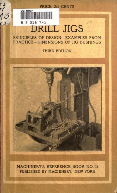
PRICE 25 CENTS<br />
1 DRILL JIGS<br />
PRINCIPLES OF DESIGN -EXAMPLES FROM<br />
PRACTICE DIMENSIONS OF JIG BUSHINGS<br />
MACHINERY'S REFERENCE BOOK NO. 3<br />
PUBLISHED BY MACHINERY, NEW YORK
MACHINERY'S REFERENCE SERIES<br />
EACH NUMBER IS ONE UNIT IN A COMPLETE LIBRARY OF<br />
MACHINE DESIGN AND SHOP PRACTICE REVISED AND<br />
REPUBLISHED FROM MACHINERY<br />
NUMBER 3<br />
DRILL JIGS<br />
THIRD EDITION<br />
CONTENTS<br />
Elementary <strong>Principles</strong> <strong>of</strong> <strong>Drill</strong> <strong>Jigs</strong>, by E, R. MARKHAM 3<br />
<strong>Drill</strong>ing Jig Plates, by J. R. GORDON - 21<br />
Examples <strong>of</strong> <strong>Drill</strong> <strong>Jigs</strong> - 27<br />
Dimensions <strong>of</strong> Standard Jig Bushings - - - - 50<br />
Using <strong>Jigs</strong> to Best Advantage, by B. P. FORTIN and J. F.<br />
MIRRIELEES 53<br />
Copyright, 1913, The Industrial Press, Publishers <strong>of</strong> MACHINERY.<br />
49-55 Lafayette Street, New York City
CHAPTER I<br />
ELEMENTARY PRINCIPLES OP DRILL JIGS*<br />
The reasons for the use <strong>of</strong> jigs may be summed up under three heads,<br />
the order in which they are stated representing fairly well the fre-<br />
quency <strong>of</strong> occurrence, though not necessarily the importance, <strong>of</strong> these<br />
reasons: First, reduction <strong>of</strong> cost; second, duplication; third, accu-<br />
racy.<br />
Let us first consider the question <strong>of</strong> cost. As no article can, as a<br />
rule, be sold in open competition with similar articles unless its cost<br />
is somewhat proportionate to the quality <strong>of</strong> its competitors, commer-<br />
cial considerations demand that the cost be kept as low as possible,<br />
while the quality be kept as high as possible; and jigs are one <strong>of</strong> the<br />
chief agents <strong>of</strong> this in metal work. When a jig is considered, the first<br />
thing to be settled is whether it can be made to pay, and if so, how<br />
much. The answer to this <strong>of</strong>ten involves very many other questions,<br />
but can generally, if not always, be resolved into computations based<br />
upon the number <strong>of</strong> pieces to be made, and the probable cost <strong>of</strong> labor<br />
per piece when made with and without a jig, and the cost <strong>of</strong> the jig,<br />
including maintenance. Also the fact that <strong>of</strong>ten a much less valuable<br />
machine, or one less busy, can be used with the jig, may be an important<br />
consideration. If no other factor than cost <strong>of</strong> production is<br />
Involved, and it is found that the total cost <strong>of</strong> the jigged work will<br />
come very near that <strong>of</strong> the lot <strong>of</strong> articles when made without a jig,<br />
and no further order is in sight, it is pretty safe to abandon the jig<br />
idea; for it is apt to partake very much <strong>of</strong> the nature <strong>of</strong> an experi-<br />
ment, and the odds should be decidedly favorable to warrant the risk.<br />
The second reason the duplication <strong>of</strong> pieces has a somewhat dif-<br />
ferent foundation though cost enters here also, as will be seen later.<br />
Suppose the part to be made is subject to wear or breakage, as in<br />
agricultural and textile machinery, guns, bicycles, etc. We know, for<br />
instance, the strong disinclination anyone has for buying a wheel, the<br />
makers <strong>of</strong> which have gone out <strong>of</strong> business. It is at once recognized<br />
that repair parts cannot be bought from stock dealers, but must be made<br />
at excessive cost and delay. So we have before us the importance<br />
to manufacturers that the buying public shall have confidence in the<br />
interchangeability <strong>of</strong> parts in order that sales may be made at all<br />
upon the open market. It is a fact that where this reason holds good,<br />
there is also the reason that costs will be lessened, because production<br />
<strong>of</strong> large numbers <strong>of</strong> parts is taken for granted. And in considering<br />
whether or not a jig shall be made, this combination <strong>of</strong> reasons militates<br />
strongly for the jig. There is also another equally important<br />
reason for jigs, based on costs and interchangeability it is that, in<br />
MACHINERY, October, 1902 ; November, 1906 ; December, 1906, and January,<br />
1907.<br />
347514
if;<br />
' v<br />
^ #fc 3 DRILL JIGS<br />
fitting and assembling, those parts which are exactly alike require a<br />
minimum amount <strong>of</strong> labor when putting in place. This, perhaps, one<br />
may, without danger <strong>of</strong> exaggeration, say is in most cases in the machine<br />
building business the chief consideration.<br />
In the third place, accuracy is <strong>of</strong>ten attained only by the use <strong>of</strong><br />
jigs. There are certain classes <strong>of</strong> work which could not be finished<br />
at all within the limits <strong>of</strong> accuracy demanded, if jigs <strong>of</strong> some sort<br />
were not used. .<br />
It will therefore be seen that the determination <strong>of</strong> whether a jig<br />
shall be made may rest upon a number <strong>of</strong> questions which <strong>of</strong>ten demand<br />
great care and practical experience to solve in the way best<br />
meeting the requirements <strong>of</strong> the case.<br />
<strong>Drill</strong> <strong>Jigs</strong><br />
<strong>Drill</strong> jigs are used for drilling holes which must be accurately<br />
located, both in relation to each other and to certain working surfaces<br />
and points; the location <strong>of</strong> the holes is governed by holes in the jig<br />
through which the drill passes. The drill must fit the hole in the<br />
jig to insure accuracy <strong>of</strong> location. When the jig is to be used in<br />
drilling many holes, the steel around the holes is hardened to prevent<br />
wear. If extreme accuracy is essential, or if the jig is to be used as<br />
'a permanent equipment, bushings, made <strong>of</strong> steel and hardened, are<br />
used to guide the drills.<br />
General Considerations in <strong>Design</strong>ing- <strong>Jigs</strong><br />
The design <strong>of</strong> a jig should depend altogether on the character <strong>of</strong><br />
the work to be done, the number <strong>of</strong> pieces to be drilled, and the degree<br />
<strong>of</strong> accuracy ncessary in order that pieces drilled may answer the purpose<br />
for which they are intended. When jigs are to be turned over<br />
and moved around on the drill press table they should be designed<br />
to insure ease and comfort to the operator when handling, and should<br />
be made as light as is consistent with the strength and stiffness<br />
necessary. Yet, we should never attempt to save a few ounces <strong>of</strong><br />
iron, and thereby render the jig unfit for the purpose we intend to<br />
use it for. The designer should see that the jig is planned so that<br />
work may be easily and quickly placed in and taken out, and that it<br />
can be easily and accurately located in order to prevent eventual mis-<br />
takes. As it is necessary to fasten work in the jig in order that it<br />
may maintain its correct position, fastening devices are used; these<br />
should allow rapid manipulation, and yet hold the work securely to<br />
prevent a change <strong>of</strong> location. Yet, while it is necessary to hold work<br />
securely, we should not use fastening devices which spring the work,<br />
or the holes will be not only improperly located, but they will not be<br />
true with the working surfaces or with each other. When finishing<br />
the surfaces <strong>of</strong> drill jigs and similar devices used in machine shops,<br />
the character <strong>of</strong> the finish depends entirely on the custom in the shop,<br />
for while in some shops it is customary to finish these tools very<br />
nicely, removing every scratch, and producing highly finished surfaces,<br />
in other shops it is not required, neither is it allowed, as it is con-<br />
sidered a waste <strong>of</strong> time and an unnecessary item <strong>of</strong> cost.
PRINCIPLES OF DRILL JIGS<br />
Limits <strong>of</strong> Accuracy<br />
When making drill jigs we must discriminate between measurements<br />
that must be exact, and those not requiring extreme accuracy; it is<br />
not considered good practice, and it shows poor judgment, to spend the<br />
amount <strong>of</strong> time necessary to locate a hole within a limit <strong>of</strong> variation<br />
<strong>of</strong> 0.001 inch or even closer, if a variation <strong>of</strong> 1/64 inch is insignificant.<br />
But if the holes must be located exact as to measurements, it is neces-<br />
sary to work as accurately as possible, and time cannot be considered<br />
a factor, provided a man improves every minute. Yet the fact that<br />
extreme accuracy must be observed does not warrant a jigmaker wast-<br />
ing time.<br />
Before starting to work on tools <strong>of</strong> this character, the workman<br />
should first carefully look over his drawing, making himself thoroughly<br />
familiar with the construction, and making sure that the measurements<br />
given are, seemingly, correct; if in doubt about anything, con-<br />
sult the foreman, or the draftsman according to the custom in the<br />
shop in order that every detail may be thoroughly understood, or<br />
that any mistake made in the drawing may be rectified.<br />
Many times .one draftsman is puzzled to understand a drawing made<br />
by an equally good man, especially so if the work is foreign to him;<br />
and a shop man, who may not be very well versed in reading drawings<br />
yet be an excellent workman may easily get puzzled when he<br />
attempts to read a drawing <strong>of</strong> work he is not familiar with. Inquiries<br />
and proper explanations are therefore in place, and there should be no<br />
hesitation about asking questions, nor any reluctance about replying<br />
to them.<br />
Provisions for Chips and Burrs<br />
It is necessary when designing tools <strong>of</strong> any character, whether they<br />
be cutting tools or fixtures for holding work while machined, to make<br />
provision for the chips. These are liable to get into drill jigs, and<br />
despite ordinary care, get under the work or between it and the locat-<br />
ing points.<br />
In order to do away, so far as possible, with this tendency,<br />
it is advisable to cut away as much <strong>of</strong> the seating surface as can be<br />
spared, and to locate stops away from the seating surface, if possible.<br />
The seating surface should be smooth enough so that chips will not<br />
adhere to it, and so that waste will not stick to it, but it should not be<br />
a polished surface, as we would in all probability get it out <strong>of</strong> true,<br />
if we attempted to polish it. If chips are allowed to get under the<br />
work it will not be drilled true; that is, the holes will not be at the<br />
proper angle with the working surface, and consequently the piece will<br />
be unfit for most purposes.<br />
Many operations <strong>of</strong> machining are almost sure to throw a burr on<br />
one side <strong>of</strong> the piece, and in shops where quantities <strong>of</strong> work <strong>of</strong> the<br />
same kind are machined, many employes are kept busy removing these<br />
burrs in order that they may not interfere with the proper seating <strong>of</strong><br />
the pieces during the succeeding operations. While the operation <strong>of</strong><br />
removing the burr on a single piece <strong>of</strong> work may not incur great cost,<br />
yet when thousands <strong>of</strong> pieces are machined each day, the aggregate<br />
cost constitutes quite an item <strong>of</strong> expense, and the successful manager<br />
5
No. 3 DRILL JIGS<br />
is he who so far as possible eliminates the small items <strong>of</strong> expense,<br />
knowing that many small items <strong>of</strong> expense amount to a large item<br />
in the aggregate. Not only is the operation <strong>of</strong> burring expensive, but<br />
as the class <strong>of</strong> help usually employed to do this work is unskilled, sur-<br />
faces are many times left in a condition anything but satisfactory.<br />
As a consequence, the surfaces <strong>of</strong> jigs, milling machine fixtures, etc.,<br />
are many times cut away to receive these burrs, thus doing away<br />
with the necessity <strong>of</strong> burring, as it many, times happens that subsequent<br />
operations remove the burrs. In Fig. 1 is shown a piece <strong>of</strong> work<br />
having a burr thrown up at a, while Fig. 2 represents a surface cut<br />
away to receive the burr.<br />
Factors Determining- the Advisability <strong>of</strong> Using- Jig-s<br />
When we wih to drill two holes a given distance apart, the location<br />
<strong>of</strong> the holes is obtained by means <strong>of</strong> a pair <strong>of</strong> dividers set to a scale.<br />
The location is obtained and prick punched, after which the holes are<br />
drilled. This method answers nicely when one piece is to be drilled,<br />
and precise measurements need not be observed. If it is necessary to<br />
_^<br />
<strong>Machinery</strong>, N.f.<br />
Figs. 1 and 2. Work with Burr, and Grooved Part <strong>of</strong> Jig to Correspond<br />
drill ten thousand pieces, then this becomes a costly method, and the<br />
work can be done more cheaply if a jig is made to hold the pieces.<br />
The jig must, <strong>of</strong> course, have holes the size <strong>of</strong> the drill, which are<br />
properly located. By the use <strong>of</strong> the jig, the cost <strong>of</strong> drilling is but a<br />
fraction <strong>of</strong> what it would be if the holes were located by dividers, and<br />
the surface prick punched as described. As we have already said, the<br />
first factor which must be considered is the cost <strong>of</strong> the jig. If the cost<br />
<strong>of</strong> the jig, plus the cost <strong>of</strong> drilling, would exceed the cost if the pieces<br />
were first prick punched and drilled as formerly described, then the<br />
making <strong>of</strong> the jig would not be considered unless a greater degree <strong>of</strong><br />
accuracy was necessary than would be liable to be the result <strong>of</strong> the<br />
method mentioned. When a jig is to become a permanent part <strong>of</strong> the<br />
equipment <strong>of</strong> a shop, its first cost is not so much a matter <strong>of</strong> consideration<br />
as when only a limited number <strong>of</strong> pieces are to be drilled. Yet<br />
no unnecessary expense should ever be allowed.<br />
Means for Locating- Work in Jig-s<br />
Many times when only two pieces are to be drilled which must be<br />
exactly alike as regards location <strong>of</strong> holes, it is cheaper to make a
PRINCIPLES OF DRILL JIGS<br />
simple jig than to attempt to drill them by any <strong>of</strong> the methods commonly<br />
used in machine shops. In such a case the jig may be made<br />
from a piece <strong>of</strong> cast iron or other material which may happen to be<br />
on hand, the holes being carefully laid <strong>of</strong>f and drilled* This jig makes<br />
it possible to drill the holes in both pieces exactly alike as to location.<br />
When using a jig <strong>of</strong> this description it is possible to locate the holes<br />
near enough for most work by ordinary measurement. If many pieces<br />
o
8 No. 3 DRILL JIGS<br />
more holes are drilled, and before all are drilled, it would cause a<br />
variation that would in all probability spoil the piece <strong>of</strong> work. When<br />
but a few pieces are to be drilled with a jig it is not generally con-<br />
sidered advisable to make jigs with fastening devices, the wor^ being<br />
held in place with a clamp, as shown in Fig. 7. In order to do away<br />
with any possibility <strong>of</strong> change <strong>of</strong> location, a pin is forced through<br />
the jig hole and the hole in the work after drilling the first hole. If<br />
many holes are to be drilled in a piece it is advisable to have two<br />
pins. After drilling a hole in one end <strong>of</strong> the piece, force in a pin;<br />
then drill a hole in the opposite end, and place a pin in this hole, as<br />
shown in Fig. 8. The pins in opposite ends <strong>of</strong> the piece will prevent<br />
ijs slipping when the rest <strong>of</strong> the holes are drilled. Many different<br />
forms <strong>of</strong> fastening devices are provided, the design depending on the<br />
class <strong>of</strong> work. One <strong>of</strong> the most positive methods consists <strong>of</strong> a screw<br />
which passes through a stud or some elevation on the jig, and presses<br />
C<br />
Fig. 7<br />
c
PRINCIPLES OF DRILL JIGS<br />
ing <strong>of</strong> the work in, or the removal <strong>of</strong> the work from the jig, or it<br />
might be necessary to turn the screw for a considerable distance each<br />
time the work was placed in or taken out <strong>of</strong> the jig. In such cases<br />
a stud could be provided that could be removed from the jig when the<br />
screw was relieved <strong>of</strong> its tension against the piece <strong>of</strong> work. Such a<br />
stud is shown in Fig. 13.<br />
Clamping- Work by Cams or Eccentrics<br />
A common method <strong>of</strong> fastening work is by means <strong>of</strong> a cam <strong>of</strong> suitable<br />
form. Cams <strong>of</strong> the ordinary design are not as powerful as the<br />
screw, but they have the advantage <strong>of</strong> being more quickly operated,<br />
Q<br />
Fig. 10<br />
Fig. 11<br />
Figs. Q to 12. Means for Clamping- Work in <strong>Drill</strong> <strong>Jigs</strong><br />
(J<br />
'<br />
Fig. 12<br />
Kachtnery.N.Tt<br />
and in the case <strong>of</strong> light work where but little strength is required,<br />
they .answer the purpose much better. The designer should bear in<br />
mind that a few seconds' time saved on each piece <strong>of</strong> work amounts to<br />
a large saving in a day when a number <strong>of</strong> hundred pieces are placed<br />
in and taken out <strong>of</strong> a jig; and in these days <strong>of</strong> competition every<br />
means <strong>of</strong> saving time consistent with quality <strong>of</strong> work should be considered.<br />
When the work bears against two points one on the side and<br />
one on the end the cam should be designed so that its travel against<br />
the work will force it against both, rather than away from one. Fig.<br />
14 shows a piece <strong>of</strong> work held by a cam which, by means <strong>of</strong> the handle,<br />
forces the work inward and in the direction <strong>of</strong> the arrow, thus hold-<br />
ing it against the locating pins a a and the end stop &. In order to<br />
get as much pressure as possible with a cam, it is necessary to have<br />
the portion that bears against the work when it is against the locating<br />
surfaces nearly concentric with the screw hole. This being the case,<br />
it is obvious that the pieces must be very nearly <strong>of</strong> one size, while<br />
in the case <strong>of</strong> a screw binder any amount <strong>of</strong> variation may be taken<br />
care <strong>of</strong>. Thus it will be seen that a screw may be used where a cam<br />
would not answer. However, it is advisable to use a cam in prefer-<br />
9
10 No. 3 DRILL JIGS<br />
ence to a screw when possible, but at times the piece <strong>of</strong> work may<br />
be subjected to repeated jars which would tend to turn a cam, thus<br />
loosening the work. In such cases a screw is preferable. If a cam<br />
would be in the way when putting in or taking out work, it may be<br />
made removable, as shown in Fig. 15. At times a tapered piece <strong>of</strong><br />
steel in the form <strong>of</strong> a wedge may be used to hold work, as shown in<br />
Fig. 16.<br />
Simple Forms <strong>of</strong> <strong>Drill</strong> <strong>Jigs</strong><br />
When many pieces are to be drilled in a jig made in the simple form<br />
shown in Fig. 17, the drill wears the walls <strong>of</strong> the holes, enlarging<br />
<strong>Machinery</strong>,<br />
Fig. 13. Clamp Screw Mounted in Removable Stud<br />
them sufficiently to render accuracy out <strong>of</strong> the question. Where jigs<br />
are to be used enough to cause this condition, the stock around the<br />
walls <strong>of</strong> the hole may be hardened, if the jig is made from a steel<br />
that will harden. If made from machinery steel, the stock may be<br />
case-hardened sufficiently to drill a large number <strong>of</strong> pieces without the<br />
LJ<br />
Fig. 14<br />
Figs. 14 and 15. Eccentric Clamp for Simple <strong>Drill</strong> <strong>Jigs</strong><br />
F i . g 1 5 <strong>Machinery</strong>,N. Y.<br />
walls wearing appreciably. This, however, would not answer when<br />
accuracy is essential, as the process <strong>of</strong> hardening would have a tendency<br />
to change the location <strong>of</strong> the holes.<br />
Guide Bushings<br />
When the jig is to be used for permanent equipment, or where many<br />
holes are to be drilled, it is customary to provide bushings guides<br />
made <strong>of</strong> tool steel and hardened. These are ground to size after hardening,<br />
and being concentric, may be replaced, when worn, by new ones<br />
<strong>of</strong> the proper size. It is the common practice to make bushings for<br />
drill jigs on the same general lines as shown in Fig. 18, the upper<br />
end being rounded to allow the drill to enter the hole readily. A head<br />
is provided, resting on the surface <strong>of</strong> the jig; the portion that enters<br />
the hole in the jig is straight, and is ground to a size that insures<br />
its remaining securely in place when in use.<br />
If the hole is sufficiently large to admit a grinding wheel, it is
PRINCIPLES OF DRILL JIGS<br />
ground to size after hardening. In such cases it is, <strong>of</strong> course, necessary<br />
to leave the hole a trifle small 0.004 inch until it is ground.<br />
If the hole is not large enough to allow <strong>of</strong> grinding, or if there is<br />
no means at hand for internal grinding, the hole may be lapped to<br />
size by means <strong>of</strong> a copper lap, using emery or other abrasive material,<br />
mixed with oil. When the hole is to be lapped rather than ground,<br />
n n<br />
11
12 No. 3 DRILL JIGS<br />
hole, unless it is bored on the taper with an inside turning tool, is not<br />
likely to produce a hole, the axis <strong>of</strong> which is at the desired angle to<br />
the surface <strong>of</strong> the jig. The outer portion <strong>of</strong> the bushing can easily be<br />
ground to the desired taper, but there is the liability <strong>of</strong> a particle<br />
Fig. 18 Fig. 19<br />
<strong>Machinery</strong>, X.T.<br />
Figs. 18 and 19. Bushing-s for <strong>Drill</strong> Jigrs<br />
<strong>of</strong> dust getting in the hole when placing the bushing in the jig. A<br />
tapered bushing, in order to get the proper taper, necessarily costs<br />
a great deal more than a straight one, and cannot answer the purpose<br />
any better, and probably not as well.<br />
Types <strong>of</strong> <strong>Drill</strong> Jig-s<br />
The shape and style <strong>of</strong> the jig must depend on the character <strong>of</strong> the<br />
work, the number <strong>of</strong> pieces to be drilled, and the degree <strong>of</strong> accuracy<br />
essential. It may be that a simple slab jig <strong>of</strong> the design shown in<br />
Fig. 20 will answer the purpose; if so, it would be folly to make a<br />
more expensive tool. If we are to drill a piece <strong>of</strong> work <strong>of</strong> the design<br />
shown to the left in Fig. 21, and but one hole is to be drilled in eacn<br />
piece, then a jig made in the form <strong>of</strong> an angle iron, as shown to the<br />
Pig. 2O. Slab Jig <strong>of</strong> Simplest <strong>Design</strong><br />
right in Fig. 21, works nicely, and is cheaply made. As it is not necessary<br />
to move the jig around on the drill press table it may, after<br />
locating exactly, be securely fastened to the table. In designing such<br />
a jig, it is advisable, when possible, to have the work on the side
PRINCIPLES OF DRILL JIGS<br />
<strong>of</strong> the upright shown in Fig. 21, rather than on the opposite side, as<br />
that does away with any tendency <strong>of</strong> the jig to tip when pressure is<br />
applied in the operation <strong>of</strong> drilling.<br />
Leaf <strong>Drill</strong> <strong>Jigs</strong><br />
For many kinds <strong>of</strong> work a jig provided with a leaf, as shown in<br />
Fig, 22, gives best results, as the leaf may be raised, and the work<br />
removed, and any dirt cleaned from the working surfaces. After<br />
placing the piece to be drilled in the jig, the leaf is closed. As the<br />
bushings are in the leaf, it is apparent that it must always occupy<br />
the same relative position to the work for the different pieces, or they<br />
will not be duplicates; consequently, the fulcrum pin, a, must be a<br />
perfect fit in the hole in the leaf, and a locating -pin & is provided to<br />
prevent any tendency <strong>of</strong> the leaf to move from the action <strong>of</strong> the drill<br />
when cutting. <strong>Jigs</strong> provided with such a pin show less tendency to<br />
wear in the joint. The leaf should not close down onto the work, but<br />
i I<br />
t 1<br />
13
14 No. 3 DRILL JIGS<br />
as few shops carry such steel in stock, crucible tool steel is generally<br />
used. The ends <strong>of</strong> the legs should be ground true with the seating<br />
surface that is, where the work rests <strong>of</strong> the jig. To accomplish this<br />
a surface grinder hould be used. As the operation <strong>of</strong> grinding leaves<br />
a number <strong>of</strong> projections on the surface ground, and as these ridges<br />
or projections would wear away as the legs were moved back and forth<br />
t<br />
PIECE OF WORK I<br />
Fig. 22. Jig with Pivoted Leaf<br />
<strong>Machinery</strong>, If. T.<br />
on the drill press table, it is advisable to remove them by lapping on a<br />
flat lap, thus producing a perfectly smooth, true surface. In this way<br />
we reduce the wear to a minimum.<br />
For certain classes <strong>of</strong> jigs the legs may be short, not more than<br />
% inch long; but for jigs <strong>of</strong> the style shown in Fig. 22, where the<br />
tool is held in the hand, it is necessary to make the legs longer to<br />
<strong>Machinery</strong>, If. Y.<br />
Pig. 23. Part <strong>of</strong> Jig -with Pivoted Leaf, Showing Method <strong>of</strong> Holding Round Work<br />
freep the fingers from coming in contact with the chips on the drill<br />
press table. The legs should be located so as to do away with any<br />
tendency <strong>of</strong> the jig to tip up when the work is being drilled.<br />
Relation Between Accuracy <strong>of</strong> <strong>Jigs</strong> and Accuracy <strong>of</strong> Machines on<br />
which They are Used<br />
While it is necessary to observe extreme care in designing drill jigs<br />
to prevent any tendency <strong>of</strong> the jig to tip, and to have the legs ground<br />
and lapped on a true plane, it is just as necessary that the drill<br />
press table should be perfectly at right angles to the spindle, and that<br />
it should be true and flat. Otherwise, the holes will not be at the<br />
desired angle with the working surface <strong>of</strong> the work.<br />
In shops where interchangeable work is produced, or where the<br />
work must in all respects be machined correctly, the condition <strong>of</strong> the<br />
various machines is closely watched, and especially such parts <strong>of</strong> the<br />
machines as affect the accuracy <strong>of</strong> the finished product. <strong>Drill</strong> press<br />
tables are planed over when out <strong>of</strong> true, or are lined up to insure their<br />
being at right angles to the spindles <strong>of</strong> the drill press. This may be<br />
done by placing a bent wire in the drill chuck, the wire being bent<br />
so that it will describe as large a circle as possible, and yet be free<br />
to swing. The end <strong>of</strong> the wire is bent so that the point will come in
PRINCIPLES OF DRILL JIGS 13<br />
contact with the table. By loosening the screws holding the table, and<br />
inserting "shims," it may be trued as desired.<br />
Locating- the Holes for the <strong>Drill</strong> Bushings<br />
When making jigs, the part <strong>of</strong> the work that calls- for the best workmanship<br />
is locating the holes for the drill bushings. The methods<br />
employed differ, but should depend on the character <strong>of</strong> the work.<br />
Where accuracy is not essential, it is the custom many times to take a<br />
piece <strong>of</strong> work that is right, or, rather, one where the holes are drilled<br />
near enough right, place this in the jig and transfer the holes into the<br />
jig. As it is necessary to leave the bushing holes in the jig considerably<br />
larger than the holes in the work in order to have sufficient stock<br />
Fig. 24. Method <strong>of</strong> Taking Vertical Measurements<br />
around the holes in the bushing, those in the jig may be enlarged by<br />
means <strong>of</strong> a counterbore, the pilot <strong>of</strong> which fits nicely in the transferred<br />
holes, and with a body the size <strong>of</strong> the desired hole. When this method<br />
does not insure desired accuracy, several other methods may be em-<br />
ployed.<br />
Making- a Jig- from a Sample Piece or Model<br />
If a model <strong>of</strong> the work to be done is at hand, a jig, as shown in<br />
Fig. 22, may be made in the following way: The leaf is raised and<br />
the model put in place. The jig is fastened to the face-plate <strong>of</strong> the<br />
lathe, the leaf still being raised. By means <strong>of</strong> a center indicator the<br />
jig is located so that one hole <strong>of</strong> the model runs true; the leaf is then<br />
closed and the hole is drilled through it, and then bored with a boring<br />
tool to the desired size. Never ream a bushing hole in a jig, or any<br />
similar hole in any piece <strong>of</strong> work, where the finished hole must be<br />
exactly located, as a reamer is liable to run out somewhat and thus<br />
affect the accuracy <strong>of</strong> the work. A reamer, if properly made and used,<br />
will produce a round, true hole, accurate as to size, and is a valuable<br />
tool for many purposes, and holes <strong>of</strong> a uniform size may be produced.<br />
But on account <strong>of</strong> the stock being uneven in texture, or on account <strong>of</strong>
1G No. 3 DRILL JIGS<br />
blow holes in castings, a reamer is liable to alter its course and so<br />
change the location <strong>of</strong> the hole. While for many purposes this slight<br />
alteration <strong>of</strong> location might be <strong>of</strong> no account, yet for work where accu-<br />
racy is essential, it is out <strong>of</strong> the question.<br />
After drilling and boring the first hole, the jig may be moved on<br />
the face-plate, and the other holes produced. It is abvious that in<br />
order to produce holes that will be at right angles to the base <strong>of</strong> the<br />
jig, the face-plate <strong>of</strong> the lathe must run true, and should be tested<br />
each time it is used for any work where accuracy must be observed.<br />
Method <strong>of</strong> Locating- Holes "When Accuracy is not Essential<br />
Where there is no model, and it is not considered advisable to make<br />
working models <strong>of</strong> the various parts, the location <strong>of</strong> the bushing holes<br />
may be obtained by laying out the various points on the jigs. In such<br />
cases a drawing is usually furnished, and the dimensions on same are<br />
transferred to the face <strong>of</strong> the jig. If it is not necessary to have the<br />
holes exact as to measurements, the laying out may be done with a<br />
surface gage, the point <strong>of</strong> the needle being set to a scale. The scale<br />
<strong>Machinery</strong>, N. Y.<br />
Fig. 25. Angle Iron -with Groove for Scale<br />
may be clamped against an angle iron, as shown in Fig. 24, or an angle<br />
iron may have a groove <strong>of</strong> the width <strong>of</strong> the scale cut across its face<br />
at right angles to the base, as shown in Fig. 25. The scale should be<br />
a good fit in the groove, so fitted that it will stay securely at any<br />
point from frictional contact with the sides <strong>of</strong> the slot, or a spring may<br />
be so arranged as to insure the proper tension.<br />
Method Assuring- a Fair Degree <strong>of</strong> Accuracy<br />
Where greater accuracy is essential, the working points should be<br />
obtained by means <strong>of</strong> a height gage, as shown in Fig. 26. By means<br />
<strong>of</strong> such a tool the measurements may be fairly accurate, as the vernier<br />
scale allows <strong>of</strong> readings to one-thousandth inch. When the lines have<br />
been scribed at the proper locations they are prick punched. In order<br />
to prick punch exactly at the intersection <strong>of</strong> lines the operator must<br />
wear a powerful eye-glass, and use a carefully pointed punch, ground<br />
to an angle <strong>of</strong> 60 degrees. If the punch marks are made very light at<br />
first, the exact location may be observed nicely. The punch marks<br />
should not be deep, as there is a liability <strong>of</strong> alteration <strong>of</strong> location if<br />
the punch is struck with heavy blows. After the various points have<br />
been located and punched, the jig may be clamped to the face-plate<br />
<strong>of</strong> the lathe, and the bushing holes carefully drilled and bored to size.
PRINCIPLES OF DRILL JIGS<br />
At times jigs are made <strong>of</strong> such size and design that it seems wise<br />
to core the bushing holes. In such cases it is necessary, in order that<br />
we may lay out the location <strong>of</strong> the centers <strong>of</strong> desired holes, to press<br />
a piece <strong>of</strong> sheet steel or sheet brass into the cored hole, as shown in<br />
Fig. 27, and locate the center on this piece. When the holes are properly<br />
located for machining, the sheet metal may be removed and the<br />
holes finished to the desired size. If an error <strong>of</strong> 0.001 or 0.002 inch is<br />
not permissible, the method described above should not be employed.<br />
Method Employed for Highest Degree <strong>of</strong> Accuracy<br />
Where extreme accuracy is essential we must locate round pieces <strong>of</strong><br />
steel on the face <strong>of</strong> our work. These pieces <strong>of</strong> steel are called buttons<br />
and are <strong>of</strong> exact size and perfectly round. To do away with any possibility<br />
<strong>of</strong> their becoming bruised in any way, they are hardened and<br />
carefully ground to size. The buttons are attached to the work by<br />
means <strong>of</strong> machine screws, as shown in Fig. 28, the holes in the but-<br />
Fig. 26.<br />
Jtactnnery.N.r.<br />
Taking Vertical Measurements by Means <strong>of</strong> Height Gage<br />
tons being larger than the screws used; this difference in size allows<br />
us to move the button until it is accurately located. The diameter <strong>of</strong><br />
the buttons should be some standard size, exactly divisible by two,<br />
because, in making our computations we only consider the distance<br />
from the center <strong>of</strong> the button to its circumference, that is, the radius.<br />
When we start to lay out the centers for the bushing holes we first<br />
determine our working surface, then lay out on the face <strong>of</strong> the jig, by<br />
means <strong>of</strong> a surface gage, as described in a previous operation, the<br />
centers <strong>of</strong> the holes to be produced. We then drill and tap screw holes<br />
to receive the screws to be used in holding the buttons to the jig.<br />
When we have prick punched the surface, and before drilling the holes,<br />
we scribe by means <strong>of</strong> dividers a circle the size <strong>of</strong> the button on<br />
17
18 No. 3 DRILL JIGS<br />
the face <strong>of</strong> the jig with the punch mark as center. This enables us to<br />
approximately locate the button. If the hole to be produced has its<br />
center 2 inches from the base a and 4 inches from vertical side &,<br />
Fig. 29, we would locate the button provided it was '% inch diameter<br />
1% inches from a, and 3% inches from &. This can be done accurately<br />
by the use <strong>of</strong> a vernier caliper, or we can lay the jig on the side &, and<br />
by means <strong>of</strong> a length gage, or a piece <strong>of</strong> wire filed to the right length,<br />
accurately determine the distance from 6 to the button. The jig is<br />
then placed on the base a and the other dimension obtained in the<br />
same manner. The buttons may be located more easily by the use <strong>of</strong><br />
a vernier height gage, if one is at hand.<br />
If there are to be several bushings on the face <strong>of</strong> a jig, a button<br />
may be accurately located where each hole is to be. The jig may be<br />
clamped to the face-plate <strong>of</strong> the lathe so that one button is located to<br />
run exactly true. This is done by means <strong>of</strong> a lathe indicator. When<br />
BRASS PIECES-<br />
<strong>Machinery</strong>, A. Y.<br />
Fig. 27. Cored Holes with Inserted Brass Pieces for Centers<br />
the jig has been so located that the button runs perfectly true, the<br />
button may be removed and the hole enlarged by means <strong>of</strong> a drill, so<br />
that a boring tool can be used to bore it to the proper diameter.<br />
1<br />
Locating the Holes on the Milling- Machine<br />
In some shops it is not considered advisable to locate a button at<br />
the desired position <strong>of</strong> each bushing hole. One button is located and<br />
the jig is fastened to the table <strong>of</strong> a milling machine having a corrected<br />
screw for each adjustment. Then, after one hole is accurately located<br />
and bored, it is a comparatively easy matter, by means <strong>of</strong> the graduated<br />
dials, to obtain the other locations; however, this method should never<br />
be used unless the machine has all its movements governed by "cor-<br />
rected" screws, as the screws ordinarily sent out on milling machine t s<br />
are not correct as to pitch, and if used, serious defects in measurements<br />
will result. Many tool-makers, therefore, prefer using a vernier scale<br />
and vernier attached to the knee and table <strong>of</strong> the milling machine,<br />
for accurate work, as they are then independent <strong>of</strong> the inaccuracies<br />
that may be present in the feed-screw.
PRINCIPLES OF DRILL JIGS 19<br />
Fig. 30 shows a jig clamped to an angle iron on the table <strong>of</strong> the<br />
'<br />
milling machine. The angle iron is located exactly in line with the<br />
travel <strong>of</strong> the table, and the jig fastened to it. The button D, which has<br />
previously been accurately located, serves as a starting point, and the<br />
jig must be located so that the button is exactly in line with the<br />
spindle <strong>of</strong> the machine. This is accomplished by moving the table<br />
Fig- 28. Buttons for Locating- Holes in Jig-s<br />
until the sleeve A on the arbor B will just slide over the button D.<br />
The hole in A must be a nice sliding fit on the arbor B and also on<br />
the button D. In order to insure accuracy, the arbor B must be turned<br />
to size in the spindle just as it is to be used; or, if a portable grinder<br />
is at hand, the arbor may be fitted to the spindle hole or to the collet,<br />
as the case may be; the portion which receives the sleeve A may be<br />
a <strong>Machinery</strong>, &*+<br />
Fig. 29. Locating a Hole by Means <strong>of</strong> a Button<br />
left a trifle large, and may be ground to size in place on the machine.<br />
The portable grinder is located on the table <strong>of</strong> the machine.<br />
After the jig has been accurately located so that the button D allows<br />
the sleeve A to slide over it, the arbor B may be removed from the<br />
spindle, and a drill be employed to increase the size <strong>of</strong> the tapped screw<br />
hole that received the screw used in fastening the button. Best results<br />
follow if a straight-fluted drill, as shown in Fig. 31, is used. The drill<br />
should not project from the chuck or collet any further than necessary,
20 fro. 3 DRILL JIGS<br />
thus insuring the greatest rigidity possible. After drilling, a boring<br />
tool <strong>of</strong> the form shown in Fig. 32 may be substituted for the drill, and<br />
the hole bored to size. The machine may now be moved to position<br />
for the next bushing hole by observing the dimensions given. The<br />
operator should bear in mind that the screw used in getting the spac-<br />
Fig. 3O. Locating Holes in the Milling Machine<br />
ings must be turned in the same direction at all times, otherwise the<br />
backlash will render accuracy out <strong>of</strong> the question.<br />
While the foregoing relates to plain jigs, the same principles apply<br />
to those <strong>of</strong> more complicated design. In the next chapter attention
CHAPTER II<br />
DRILLING JIG PLATES*<br />
A description <strong>of</strong> the following method cf drilling, jig plates was con-<br />
tributed to the columns <strong>of</strong> MACHINERY, October, 1902, by Mr. J. R. Gordon.<br />
The method being radically different from any <strong>of</strong> those in common<br />
use, it has been deemed proper to mention this method in connec-<br />
tion with other methods for locating the holes in jigs already<br />
referred to.<br />
In the case in question, a great many jigs were to be made, and the<br />
positions <strong>of</strong> the drill bushings were to be accurate within 0.001 inch.<br />
The procedure was as follows: The regular work-table from an ordi-<br />
nary sensitive drill press <strong>of</strong> the usual pattern was removed, and substituted<br />
by one <strong>of</strong> larger dimensions, as this was called for by the size <strong>of</strong><br />
the jig plates to be made.<br />
This table was first planed on the face and edges, and the stem, by<br />
which it is held in the bracket on the column <strong>of</strong> the press, was turned<br />
to fit snugly the hole in the bracket. After planing and turning the<br />
table, a series, <strong>of</strong> holes was drilled, as shown in Fig. 34, and they were<br />
tapped to receive a No. 14-20 screw. Two parallel pieces G and D,<br />
Fig. 34, having straight edges and a thickness <strong>of</strong> % <strong>of</strong> an inch, were<br />
made. These may be clamped to the table in such a position as nay be<br />
desired or the work determine, the series <strong>of</strong> holes permitting any<br />
adjustment within the range <strong>of</strong> the table. In order to make more room<br />
between the spindle and the column <strong>of</strong> the drill press, the spindle<br />
head was blocked out, the block having a projecting lug, as shown at<br />
A, Fig. 33, to which a bracket, F, was fastened to carry the bushing, B.,<br />
This bushing is fastened by a screw and can readily be removed and<br />
others inserted, having various sizes <strong>of</strong> holes, if found desirable. These<br />
preparations were all that were necessary with the exception <strong>of</strong> the<br />
gages that will be described in the operation <strong>of</strong> the method for spacing,<br />
which is as follows:<br />
The plate to be drilled had a number <strong>of</strong> holes spaced as shown in<br />
Fig. 34, and before drilling them they were marked as Nos. 1, 2, 3,<br />
etc., No. 1, as will be seen, being the upper left-hand hole. Its location<br />
with reference to either end or sides <strong>of</strong> the plates did not require<br />
to be very exact; but other plates may need to have holes placed at<br />
some definite distance from the edges or ends, so it may be assumed<br />
that the distance is 6 inches from the edge, G, and 8 inches from the<br />
end, H.<br />
With these distances given, make two gages, using vernier or<br />
micrometer calipers for standard, and make them 6% and 8% inches<br />
long, respectively. Remove the bushing, B, Fig. 33, and in its place<br />
insert a plug having a diameter <strong>of</strong> Vt inch:<br />
* MACHINERY, October, 1002.
22 No. 3 DRILL JIGS<br />
Resting the 6% gage on the table, and with one end touching the<br />
plug, the parallel piece, (7, Fig. 34, is brought to just touch the other<br />
end <strong>of</strong> the gage and is then clamped to the table! This is not very<br />
difficult if one end <strong>of</strong> the parallel is left free and the other end<br />
is clamped tight enough to permit the free end to move somewhat<br />
stiffly: After locating and clamping the parallel, C, the other parallel<br />
Fig. 33. <strong>Drill</strong> Press arranged for <strong>Drill</strong>ing Jig Plates<br />
is clamped in position, but it must be placed square with the first<br />
parallel. This is more difficult than in the first case, but is not at all<br />
difficult if one man can be employed to clamp the piece while another<br />
holds the square and gage.<br />
The reason for making the gages 6% and<br />
Sy8 inches long instead <strong>of</strong> 5% and 7% inches, respectively, is that it is<br />
not desirable to have the edges <strong>of</strong> the plate touch against the parallels,<br />
as chips could get between the two and destroy the accuracy <strong>of</strong> the<br />
measurements; allow the gage to be 14 inch longer than the distance
DRILLING JIG PLATES 23<br />
required, and fill in .the space with % inch diameter gages, as shown<br />
in Fig. 34.<br />
For gages over 1 inch in length use flat brass rods or strips about<br />
thick, and cut them a little longer than the<br />
% inch wide and , y8 inch<br />
I<br />
O O O O O O<br />
I tnJu*irial pr*, ff. f.<br />
Fig. 34. Plate in Position for <strong>Drill</strong>ing First Hole<br />
finished length. One end is finished square and the other end is<br />
rounded as shown in Fig. 35. In making the gage, if too much metal<br />
is removed, it is an easy matter to pene the stock out to make up<br />
for any reasonable error. The length <strong>of</strong> the gage is stamped on it, and<br />
when the operation is completed it is put away for future use.<br />
Having located the parallels, the plug is removed from the bracket<br />
Industrial Pr<br />
Fig. 35. Type <strong>of</strong> Gage used when <strong>Drill</strong>ing Jigr Plates<br />
and the bushing replaced. The drill should, <strong>of</strong> course,<br />
fit as snugly<br />
to the hole in the bushing as it can and run without cutting. The<br />
bushing should support the drill to within a distance equal to the<br />
diameter <strong>of</strong> the drill from the plate to be drilled, and care should be<br />
taken not to drill through the plate until all the holes have been<br />
started. After drilling the first hole, to place the plate for the second<br />
hole, distant 2 inches from the first, it is moved along the parallel, C,
24 No. sDRILL JIGS<br />
and a gage 2^ inches long placed as shown in Fig. 36, and when so<br />
placed is ready for drilling. The third hole requires three new gages,<br />
since it is 1 inch <strong>of</strong>f the line <strong>of</strong> the other two holes, as shown in Fig. 37.<br />
For holes which are to be finished 3/16 inch to % inch in diameter,<br />
use first a small drill, size No. 52 to No. 30. After the holes are all<br />
drilled to this size, then enlarge them, by the use <strong>of</strong> a series <strong>of</strong> four<br />
lip counterbores, to the required size. Where extreme accuracy is<br />
required, in the place <strong>of</strong> the counterbore, a small boring bar may be<br />
substituted and the holes bored to the size desired. One disadvantage<br />
<strong>of</strong> using a boring tool is that it requires a hole in the table equal to<br />
the largest hole to be bored out, or that the plate shall be kept clear<br />
<strong>of</strong> the table by blocking up with parallel strips under it.<br />
G-<br />
Induttrial /'/, N.Y.<br />
Fig. 36. Plate in Position for <strong>Drill</strong>ing- Second Hole<br />
Fig. 38 shows a form <strong>of</strong> boring tool which will be found very convenient<br />
for use on this kind <strong>of</strong> work. It consists <strong>of</strong> the shank, A,<br />
which is fitted to the taper hole in the spindle, and a split holder, B,<br />
which is pivoted to the shank at C, and is locked to it at D, the screw<br />
at D serving to clamp the boring tool, E, at one end, while F clamps<br />
It at the other end. Adjustment is obtained by swinging the holder,<br />
the radial slot, G, allowing it to have quite a range, and the top screw,<br />
IT, permitting fine adjustment. Split bushings in the holder will allow<br />
the use <strong>of</strong> boring tools <strong>of</strong> smaller diameter if desired.
DRILLING JIG PLATES<br />
This method <strong>of</strong> locating holes is not limited to the drill press, but<br />
may be employed to advantage on the face-plate <strong>of</strong> a lathe. In this<br />
case, the work, as soon as located by the gages, is clamped to the face-<br />
plate.<br />
While this method was originated for drilling holes in jig plates, it<br />
may be used with equal success for drilling small interchangeable<br />
pieces. It is not necessary that the edges, G and H, be planed at right<br />
angles, as the same results will be obtained if the surface, G, is planed<br />
true and a finished spot provided at K, from which point all measurements<br />
to the parallel, D, are made.<br />
H.<br />
G-<br />
Industrial PrtU, A', f.<br />
Fig. 37. Plate in Position for <strong>Drill</strong>ing Third Hole<br />
Mr. Gordon claims that this system has certain advantages over the<br />
button methods used on the milling machine. In the first place, the<br />
feed-screws on nearly all milling machines are not correct, and in some<br />
shops the tool equipment is so badly worn as to make the use <strong>of</strong> the<br />
feed-screws out <strong>of</strong> the question for accurate work.* However accurate<br />
a screw on a milling machine is when new, it soon loses its truth<br />
under ordinary conditions <strong>of</strong> machine shop practice, since only a small<br />
* See page 18 : Locating the Holes on the Milling Machine.
26 No. 3 DRILL JIGS<br />
portion <strong>of</strong> the screw is used to do most <strong>of</strong> the work <strong>of</strong> driving the<br />
table. In the second place, Mr. Gordon claims that his method is<br />
quicker, the supposition being that the necessary appliances, such as<br />
parallels, brackets, bushings, etc., are made and ready for use; and<br />
finally, that there is a very small chance for errors, provided that<br />
the gages used are marked distinctly.<br />
These assertions, however, called forth considerable comment in the<br />
columns <strong>of</strong> MACHINERY. Mr. Frank E. Shailor, in particular, took issue<br />
with Mr. Gordon on account <strong>of</strong> these assertions and claimed that there<br />
were considerable chances for errors. Mr Gordon, however, defended<br />
L J I<br />
I DLEJ<br />
Fig. 38. Boring Tool<br />
his method, pointing out that most <strong>of</strong> Mr. Shailor's objections were<br />
<strong>of</strong> little consequence, provided proper precautions were taken. Other<br />
contributors added their word to the discussion, some siding with Mr.<br />
Gordon, and some admitting that the methods used both by Mr. Gordon<br />
and Mr. Shailor would, under proper circumstances, be correct to use.<br />
It is not possible in this treatise to give place to what was more a<br />
personal controversy, than <strong>of</strong> direct bearing upon the subject <strong>of</strong> drill<br />
jig design. It may, however, be proper to mention that the discussions<br />
on this subject appeared in the July, August, September and<br />
November, 1904, and the January and February, 1905. issues <strong>of</strong><br />
MACHINERY.
CHAPTER III<br />
EXAMPLES OF DRILL JIGS<br />
In the following will be given a number <strong>of</strong> examples <strong>of</strong> drill Jig<br />
designs for definite purposes, as employed in various shops in the<br />
country. No attempt has been made to show only jigs <strong>of</strong> which it can<br />
be said that the design is perfect or nearly so, but examples have been<br />
taken which indicate general practice, and attention has been called<br />
to wherein these jigs conform to the principles <strong>of</strong> drill jigs as treated<br />
in Chapter I, and also to the objections that might be raised against<br />
each particular design, if such objections have been considered in<br />
Fig. 39. Jig for <strong>Drill</strong>ing Holes In Studs and Shafts<br />
place. The names <strong>of</strong> the persons who originally contributed to the<br />
columns <strong>of</strong> MACHINERY the descriptions <strong>of</strong> the devices shown, have<br />
been given in notes at the foot <strong>of</strong> the pages, together with the month<br />
and year when their contribution appeared.<br />
<strong>Jigs</strong> for <strong>Drill</strong>ing Pin Holes in Shafts<br />
Usually, the simplest kinds <strong>of</strong> jigs are those intended for drilling a<br />
hole through the center <strong>of</strong> a shaft They <strong>of</strong>ten consist only <strong>of</strong> a
28 No. 3 DRILL JIGS<br />
V-block, in which the work rests, and a cover <strong>of</strong> the simplest design,<br />
containing the guide bushing. Sometimes, however, they are made<br />
more universal; the cuts Figs. 39 and 40 show two such designs.<br />
The jig in Fig. 39 is intended for drilling pin holes in comparatively<br />
short studs, and will handle a variety <strong>of</strong> such work with great rapidity.<br />
The drill bushing A can be removed and bushings with different size<br />
holes inserted. The bushing holder B can be raised or lowered to suit<br />
'<br />
different diameters <strong>of</strong> work. The V-block C is fixed, while block D is<br />
adjustable by means <strong>of</strong> the screw E for different lengths <strong>of</strong> studs. By<br />
fastening a strap to the device by screw F, and providing this strap<br />
with an adjustable screw in line with the V's, studs can be gaged from<br />
the end instead <strong>of</strong> from the shoulder, which, when used for gaging,<br />
rests against the sides <strong>of</strong> either <strong>of</strong> the V-blocks. The manner in<br />
which this jig is used lends itself well to a variety <strong>of</strong> work <strong>of</strong> all<br />
descriptions.*<br />
Fig. 4O. Jig for <strong>Drill</strong>ing Holes in Shafts<br />
Induatrivl fret*, N.Y.<br />
This jig is a simple, yet efficient and characteristic, example <strong>of</strong> the<br />
adjustable type <strong>of</strong> jig. It will be noticed that the design does not<br />
provide for any clamping device for the work to be drilled; this is on<br />
account <strong>of</strong> that in this case the holes to be drilled are so small, com-<br />
pared with the diameter <strong>of</strong> the shaft or stud, that the stud will stay<br />
in place by its own weight, or by pressure <strong>of</strong> the hand on its .upper<br />
side, the V-groove aiding materially in keeping the work in position.<br />
The device shown in Fig. 40 is another example <strong>of</strong> an adjustable jig<br />
for this class <strong>of</strong> drilling. This tool has proved to be <strong>of</strong> the greatest<br />
convenience for drilling shafts, spindles or other round pieces. The<br />
base A is dovetailed and fitted with a lead-screw, which moves the<br />
slide B in and out. Upon this slide is mounted the adjustable V-block<br />
C, which can be tipped at any desired angle for oblique drilling, or set<br />
perpendicularly to hold the shafts in position for end drilling. The<br />
adjustable stud D is placed under the outer end <strong>of</strong> the block to hold it<br />
firmly in any set position. The arm E is adjustable up and down, for<br />
different sized shafts, and is supplied with a complete set <strong>of</strong> bushings<br />
for use with drills <strong>of</strong> different diameters. When mortising bars, intended<br />
to be used as holders for facers, boring cufters, counterbores<br />
Paul W. Abbott, August, 1907.
EXAMPLES OF DRILL JIGS<br />
with interchangeable blades, etc., the work is clamped into the V with<br />
the clamp F, and then, after the first hole has been drilled, the slide<br />
is moved along for a distance equal to the diameter <strong>of</strong> the drill, and<br />
the next hole drilled, and so on. By this method any number <strong>of</strong> holes<br />
can be drilled in perfect line, and always through the center <strong>of</strong> the<br />
bar. By the use <strong>of</strong> a stop clamped across the end <strong>of</strong> the V-block, the<br />
attachment forms a jig which can be used for a great variety <strong>of</strong> dupli-<br />
cate drilling.*<br />
A jig for drilling cotter-pin holes, which facilitates the operation<br />
considerably as compared with the way it is commonly done, is shown<br />
in Fig. 41. It consists <strong>of</strong> two pieces <strong>of</strong> steel forming a clamp, each<br />
piece having a V-groove to receive different diameters <strong>of</strong> studs. The<br />
THIS SIDE USED FOR<br />
THICKER WASHER AND<br />
LARGER COTTER PIN.<br />
41. Jig: for <strong>Drill</strong>ing: Cotter-pin Holes<br />
upper one contains two holes which correspond with the size <strong>of</strong> cotter-<br />
pins desired. Should more than the two sizes be required, extra top<br />
pieces can be used with the same bottom piece. Part <strong>of</strong> the upper<br />
piece is cut a,way on each side in line with the edge <strong>of</strong> the holes,<br />
which allows the washer to be used to be inserted at the recess, and<br />
the jig then clamped in position. By this means no scribing or spot-<br />
ting is necessary and a much better job can be done. Although it is<br />
shown so in the cut, it is obvious that the male portion <strong>of</strong> the joint<br />
need not be in position when drilling.<br />
<strong>Jigs</strong> for <strong>Drill</strong>ing- Collars<br />
The jig shown in Fig. 42 has been used with much satisfaction for<br />
drilling set-screw holes in collars, The collar C is held in position by<br />
means <strong>of</strong> the three locating pins D, D, D, and the swinging clamp E.<br />
In order to place a collar in position for drilling, the strap is swung<br />
* Roy W. Harris, April, 1903.<br />
29
30 No. j DRILL JIGS<br />
to one side about the hand screw G. When the collar has been put in<br />
place the clan?p is swung back, and in doing so, its motion is limited<br />
by the pin F, which brings it to a stop directly over the collar. At<br />
the top <strong>of</strong> the jig is a bushing B through which the drill is guided.<br />
When the outside diameter <strong>of</strong> the collars is likely to vary, the pins<br />
/), D, D, may be replaced by a central pin, L, as shown in the separate<br />
view in the cut, and the collar held on this while it is being drilled.*<br />
The jig shown in Fig. 43 is designed for drilling the holes in the<br />
center <strong>of</strong> collars, and the method <strong>of</strong> drilling, described below, also sug-<br />
gests the value <strong>of</strong> systematizing the work in using jigs. The collars<br />
to be drilled are made <strong>of</strong> annealed tool steel in sizes varying in thick-<br />
ness as well as in diameter and size <strong>of</strong> hole, and are cut <strong>of</strong>f from the<br />
t? Industrial<br />
Fig. 42. Jig for <strong>Drill</strong>ing Set-screw Holes in Collars<br />
Prttf, ft. Y<br />
bar on the cold saw. There being a three-spindle gang drill in the<br />
shop, which was idle part <strong>of</strong> the time, it was decided to make use <strong>of</strong><br />
it in the production <strong>of</strong> these collars. Four jigs like the one shown in<br />
the cut were made. They were made to take any diameter or thickness<br />
<strong>of</strong> collars within their range. The body <strong>of</strong> the jig is a square block <strong>of</strong><br />
steel, with the hole to receive the collars exactly in the center. The<br />
lower end is threaded left-hand to receive the piece B, which has a<br />
square hole in the center to receive the wrench C. The ring D Is<br />
bored taper, and fits the collar operated upon at the top end only, so<br />
that the collars will drop out <strong>of</strong> the jig easily. Different rings are<br />
made to fit collars <strong>of</strong> different diameters, and are just an easy drive<br />
fit in A, the body <strong>of</strong> the jig. They are driven out with a s<strong>of</strong>t punch<br />
through hole E in piece A. <strong>Drill</strong> bushings F are also interchangeable.<br />
Piece G is a distance piece used when drilling thin collars in order to<br />
avoid screwing piece B into the jig too far. It is apparent from the<br />
cut that these pieces are made to fit the collar at one end, and beveled<br />
at the other to center in piece B. The reason piece B is threaded<br />
left-hand is as follows: If the collar operated upon should turn in<br />
C. H. Rowe, January, 1903.
EXAMPLES OF DRILL JIGS<br />
the jig, the piece B, taking the thrust, would also turn, and being<br />
threaded left-hand would thereby tighten the collar in the jig. Piece<br />
H is a channel iron the function <strong>of</strong> which is to hold the jigs while re-<br />
one <strong>of</strong> the jigs is placed upon the drill press<br />
filling. In operation, .<br />
table under each spindle between flat strips 7, which keep the jigs<br />
from turning, at the same time leaving them free to be removed for<br />
refilling. It will be seen that by having four jigs, and a three-spindle<br />
machine, by timing them so that they will finish the holes one after<br />
the other, it will give plenty <strong>of</strong> time to refill the fourth jig, and there-<br />
by, with an extra drill or two kept sharpened by the tool grinder, the<br />
Fig. 43. Jig for <strong>Drill</strong>ing Collars<br />
<strong>Machinery</strong>, N.r.<br />
machine may be kept in constant operation. This machine is equipped<br />
with a pump keeping a constant flow <strong>of</strong> cutting fluid on the drills. As<br />
this machine is also handled by comparatively cheap labor, a saving<br />
<strong>of</strong> almost 75 per cent was shown by actual test over methods previ-<br />
ously employed in producing these collars on a turret lathe.<br />
If ft were not possible to use four jigs at a time <strong>of</strong> the kind just de-<br />
scribed, three being in operation, while one is in the hands <strong>of</strong> the<br />
operator for removing the drilled piece and inserting a new one, there<br />
would be one serious objection to the design <strong>of</strong> the jig shown. The<br />
time required for unscrewing, and again tightening, the clamping col-<br />
lar B, being threaded for its full length into body A, would be too long<br />
to permit rapid work. Therefore, in a case where but one jig could<br />
be used, the clamping device should be arranged so that the drilled<br />
piece can be removed, and a new one clamped in place instantly. This<br />
can be accomplished by some kind <strong>of</strong> a hinged or swinging cover, provided<br />
with a threaded binder; one half turn <strong>of</strong> the binder would be<br />
sufficient to clamp the work. In the case in hand, however, the sys-<br />
31
32 No. 3 DRILL JIGS<br />
tern <strong>of</strong> using the jigs makes this objection <strong>of</strong> less consequence, as the<br />
operator has plenty <strong>of</strong> time to attend to one jig while the collars in<br />
the others are being drilled.<br />
Flang-e <strong>Drill</strong>ing- Jig's<br />
Two examples <strong>of</strong> flange drill jigs are given in Figs. 44 and 45. The<br />
jig in Fig. 44 is <strong>of</strong> the simplest form for this kind <strong>of</strong> work, being<br />
merely a templet, while Fig. 45 shows the. appearance and application<br />
<strong>of</strong> a more universal device, provided with an indexing plate. In<br />
cases where flanges and fittings are to be interchangeable, or to be<br />
duplicated at different times, the only accurate method <strong>of</strong> drilling such<br />
fittings is, <strong>of</strong> course, by means <strong>of</strong> a jig or templet which prevents any<br />
error arising when such parts are duplicated.<br />
1<br />
Fig.. 44. Templet Jigr for <strong>Drill</strong>ing Flanges<br />
Jfachinery 2f.Y.<br />
The templet, Fig. 44, combines simplicity and cheapness. The ring<br />
proper may be made from a companion flange, the size for which the<br />
templet is to be used, by cutting <strong>of</strong>f the head and finishing all over, the<br />
thickness being approximately one inch. Diameter B is made equal to<br />
the outside diameter <strong>of</strong> the flange, and A is the diameter <strong>of</strong> the bolt circle.<br />
A removable bushing, such as shown in section x-y, is used and<br />
moved from hole to hole as required. The advantage <strong>of</strong> this loose bush-<br />
ing over a stationary one in each hole is obvious, lessening the cost <strong>of</strong><br />
the templet more than one-half. The bushing is made from machine<br />
steel, knurled where indicated, and hardened. The small pin prevents<br />
the bushing from revolving in its hole with the drill. In such cases<br />
where a drilling job calls for the same number <strong>of</strong> bolts in the s&me<br />
bolt circle, but different sizes <strong>of</strong> bolts, all that is necessary is to have<br />
two bushings, with the same diameter E, while C is made to correspond<br />
with the diameter <strong>of</strong> holes required.*<br />
In Fig. 45 an adjustable type <strong>of</strong> jig and the work for which it is<br />
used are shown. As the number <strong>of</strong> holes in the work to be drilled, as<br />
* Calvin B. Ross, May, 190G.
EXAMPLES OF DRILL JIGS<br />
well as the diameter, varies, it would cost considerable to make individual<br />
jigs to do the work. The features <strong>of</strong> this jig are a small center<br />
plate, provided with holes for indexing, as shown at the center <strong>of</strong> the<br />
cut, and a removable arm which carries the drill bushing. The index<br />
plate is held in position by a nut on the under side <strong>of</strong> the work, and<br />
the position <strong>of</strong> the arm is fixed by a plug or pin which passes through<br />
the arm and into the plate. The bolt at the outer end <strong>of</strong> the arm is<br />
made <strong>of</strong> a suitable form to clamp on the under side <strong>of</strong> the work, and<br />
is tightened by the handle shown, which avoids the use <strong>of</strong> a wrench.<br />
Fig. 45. Adjustable Flange <strong>Drill</strong>ing Jig<br />
By loosening this handle and withdrawing the locating plug, the arm,<br />
can be turned to the next division, the plug inserted and the hole<br />
drilled. Different diameters may be drilled by using arms <strong>of</strong> suitable<br />
length, the same dividing plate answering for a wide range <strong>of</strong> sizes.*<br />
<strong>Jigs</strong> <strong>of</strong> the description shown in the cuts, Figs. 44 and 45, are, <strong>of</strong><br />
course, not intended for extreme accuracy, but rather for combining<br />
the objects <strong>of</strong> rapid production <strong>of</strong> work within commercial limits <strong>of</strong><br />
accuracy, cheapness <strong>of</strong> tools, and possibility <strong>of</strong> accommodating a wide<br />
range <strong>of</strong> work with the same devices.<br />
Adjustable <strong>Jigs</strong><br />
It is not always possible to provide jigs with adjustable features,<br />
particularly not when a great degree <strong>of</strong> accuracy is required. A great<br />
* M. A. Palmer, June, 1907.<br />
33
34 No. 3 DRILL JIGS<br />
many operations in the shop, however, permit <strong>of</strong> so wide a limit <strong>of</strong><br />
error that fairly accurate jigs can be designed which, having a certain<br />
degree <strong>of</strong> flexibility, will accommodate a variety <strong>of</strong> work. These jigs<br />
are valuable in a double measure. In the first place they save a great<br />
deal <strong>of</strong> outlay for individual jigs, and, secondly, many a little job,<br />
for which no individual jig would be warranted, may be drilled in an<br />
adjustable jig at a great saving <strong>of</strong> time and gain in accuracy.<br />
The jig shown in Fig. 46, in use in the W. F. & John Barnes shops,<br />
Rockford, 111., is designed with the purpose <strong>of</strong> securing adjustability,<br />
so as to adapt the jig to pieces <strong>of</strong> different shapes and dimensions. The<br />
base piece A supports an upright F, to which the knee, E, is bolted.<br />
This knee holds the drill bushing and is tongued and grooved to the<br />
Jndwitrial Pres,y.y.<br />
Fig. 46. Adjustable <strong>Drill</strong> Jigr<br />
upright so that it may be raised or lowered for work <strong>of</strong> different<br />
heights. The work is held by two slides, B and (7, and a set-screw D.<br />
The lower slide, C, has a tongue fitting in a groove in the base, and<br />
one end is V-shaped to give support to the lower end <strong>of</strong> the work,<br />
against which it is made to bear. The slide B has a tongue fitting<br />
in a groove in the top <strong>of</strong> the lower slide, and may thus be adjusted in-<br />
dependently <strong>of</strong> the latter.<br />
An adjustable jig also provided with an indexing feature, is shown<br />
in Fig. 47.. This jig is intended for drilling the clearance holes in<br />
small threading dies. As these holes are located on different distances<br />
from the center according to the diameter <strong>of</strong> the thread the die is intended<br />
to cut, one jig would be necessary for each diameter <strong>of</strong> thread<br />
in the die, although the outside dimensions <strong>of</strong> the die blanks are the<br />
same for wide ranges <strong>of</strong> diameters <strong>of</strong> thread. To overcome the neces-<br />
sity <strong>of</strong> so many individual jigs, an adjustable strap or slide C is pro-
EXAMPLES OF DRILL JIGS<br />
vided, which can be adjusted to drill holes at different radii from the<br />
center <strong>of</strong> the blank, and will locate the center hole in the blank when<br />
a mark on the slide coincides with the "center line" graduation on the<br />
holder plate. The die blank is placed in holder B, being secured there-<br />
in by the set-screws located as shown. This holder is readily rotated,<br />
as it is knurled on the edge <strong>of</strong> the flanges. It has four equally spaced<br />
locating holes, into which locating pin D enters.*<br />
Miscellaneous Examples <strong>of</strong> <strong>Drill</strong> <strong>Jigs</strong><br />
A type <strong>of</strong> drilling jig containing features that merit the attention<br />
<strong>of</strong> the jig designer is shown in Fig. 49. One <strong>of</strong>ten sees expensive and<br />
complicated jigs used where one <strong>of</strong> this type would have done as well.<br />
In some shops this type has reached a high state <strong>of</strong> development, due<br />
Pig. 47. Adjustable Jig for <strong>Drill</strong>ing Threading- Dies<br />
Industrial Prv, K.T.<br />
to conditions that favor the adoption <strong>of</strong> a cheap and quickly made jig,<br />
namely: A constantly changing product, few pieces to be drilled <strong>of</strong><br />
each kind, and the fact that the jigs are always wanted in a hurry.<br />
In designing jigs under these conditions, the problem resolves itself<br />
into building a cheap jig, and not accumulating a large number <strong>of</strong> use-<br />
less patterns.<br />
Fig. 48 shows the piece to be drilled and detail <strong>of</strong> clamp and feet.<br />
The plan and side views <strong>of</strong> the jig, with the work in position, are<br />
shown in Fig. 49, in which cut the jig is shown bottom side up. A<br />
cast-iron plate A is used, in which the required number <strong>of</strong> holes are<br />
drilled for the insertion <strong>of</strong> hardened bushings, and there are two locat-<br />
ing pins, shown in the plan view at & 6. C is a locating and clamping<br />
plate which is kept central by the four pins d. The V in the clamping<br />
plate locates the work in a central position, and as the plate also<br />
I. B. Niemand, February, 1902.<br />
35
36 No. 3 DRILL JIGS<br />
extends over the top <strong>of</strong> the work and clamps down upon it,<br />
it holds<br />
the work securely in place. The clamp is bolted to the plate by the<br />
screw h, and the work is clamped by screw g at the other end. Four<br />
Industrial Petti, A'.F.<br />
Fig. 48. Piece to be <strong>Drill</strong>ed in Jig, Fig. 49, and Detail <strong>of</strong> Clamp and Feet<br />
legs c support the body plate A, and raise it up high enough so that<br />
the work clears the table when the jig is placed in position for drilling.<br />
The oblong hole in the plate C permits the clamp to be moved<br />
back far enough to get the work in and out <strong>of</strong> the jig.<br />
JnJuttriaL Preu, ff.T.<br />
"Fig. 49. Jig for <strong>Drill</strong>ing Piece Shown in Fig. 48, with Work in Position<br />
Large size plates, all planed up, may be kept in stock for the jig<br />
bodies so that, pieces <strong>of</strong> the required size can be readily cut <strong>of</strong>f when
EXAMPLES OF DRILL JIGS<br />
needed. This jig is very accurate, as with it the work can be brought<br />
close to the plate containing the drill bushings.*<br />
The drill jig shown in Fig. 51 has proved very efficient for maintaining<br />
uniformity in the pieces drilled in this jig, one <strong>of</strong> which is shown<br />
in Fig. 50. For the work it is intended to do, this jig is rigid and<br />
simple and is designed to withstand the severe handling that a tool<br />
Fig. 5O. Work to be <strong>Drill</strong>ed in Jig, Fig. 51<br />
<strong>of</strong> this kind usually receives from unskilled workmen. The pieces to<br />
be drilled are first turned in the lathe to the proper size and length,<br />
and the hole through the center is drilled at the same time. The<br />
object <strong>of</strong> the jig is to drill the side holes and the two end holes, which<br />
are diametrically opposite, one <strong>of</strong> them being stopped <strong>of</strong>f at % inch<br />
from the bottom and continued through with a smaller size <strong>of</strong> drill.<br />
Pig. 51. Jig for <strong>Drill</strong>ing Work shown in Pig. 5O<br />
The jig consists <strong>of</strong> an L-shaped casting, A, which is supported on its<br />
bottom and side by the steel legs, BB, the faces <strong>of</strong> which are hardened<br />
and lapped true. A hole is drilled straight through the jig from top to<br />
bottom, and into the top <strong>of</strong> this hole is forced the bushing, C, <strong>of</strong> tool<br />
steel, having a No. 19 and a ^4-inch hole, and also a guide for one end<br />
<strong>of</strong> the work projecting at the center on the lower side. The bushing<br />
* Louis Meyers, February, 1902.<br />
37
38 No. 3 DRILL JIGS<br />
C is forced into the jig from the inside until the shoulder bears firmly<br />
against the upper arm <strong>of</strong> the jig. This combined bushing and guide is<br />
made in a. single piece, instead <strong>of</strong> inserting drill bushings and a guide<br />
piece separately, because the variation allowed for the holes is greater<br />
than any that is likely to be incurred in the hardening <strong>of</strong> the bushing.<br />
Fitted tightly in the hole in the base <strong>of</strong> the jig is the sleeve, D,<br />
which carries a traversing piece, E, with a guide point on one end<br />
directly opposite and like the one in the upper bushing. These guides<br />
fit the hole in the work, which is advanced or withdrawn by means<br />
<strong>of</strong> the screw F, which is fastened to the piece E by the pin, G, introduced<br />
in such a location that the side rests in a round groove on the<br />
upper end <strong>of</strong> the screw, attaching it thereto and at the same time<br />
permitting it to rotate freely. The end <strong>of</strong> a small pin, H, enters a<br />
spline in the side <strong>of</strong> E and checks any tendency to revolve when the<br />
screw is being turned. A knurled head is pinned and riveted on the<br />
1 BRASS CASTING<br />
1 H C.R. STEEL PIN<br />
1 39. BESS. WIRE PIN<br />
Fig. 52 Fig. 53<br />
<strong>Drill</strong>ing' and Assembling Jig<br />
FOR DRILLING HOLE<br />
FOR CROSS PIN<br />
PUNCH FOR<br />
DRIVING STUDS<br />
Xachinerv,N.Y.<br />
Fig. 54<br />
end <strong>of</strong> F. A strip <strong>of</strong> machine steel, J, <strong>of</strong> sufficient length to extend<br />
from top to bottom <strong>of</strong> the jig, is seated in a rectangular milled channel<br />
and fastened by screws and dowel pins. The side holes are carefully<br />
located in this strip, and two hardened and ground bushings for No. 4<br />
drills are pressed in.<br />
When in use, the work is slipped on the upper guide point, and,<br />
when the piece E is advanced by the hand screw, it is held firmly in<br />
place, being properly located in relation to the bushings by the center<br />
hole. The piece is then drilled as in ordinary jig drilling, the finished<br />
piece being removed by simply loosening up the hand screw. The piece<br />
E, with the exception <strong>of</strong> the guide on its end, is left s<strong>of</strong>t for the point<br />
<strong>of</strong> the drills to enter the necessary depth for clearance.*<br />
* C. n. Rowe, December, 1903.
EXAMPLES OF DRILL JIGS<br />
<strong>Drill</strong>ing- and Assembling- Jig-<br />
Sometimes drill jigs are designed for the performing <strong>of</strong> other operations<br />
in connection with the work than that <strong>of</strong> drilling alone. In<br />
Fig. 53 is shown a combined drilling and assembling jig which was<br />
designed and made for the purpose <strong>of</strong> facilitating the manufacture <strong>of</strong><br />
the part shown in detail in Fig. 52. This detail consists <strong>of</strong> a brass<br />
casting A having a small machine steel stud B driven into its center<br />
and securely held against turning by a small bessemer wire pin through<br />
both casting and stud.<br />
During the ordinary course <strong>of</strong> manufacturing with a plain drilling<br />
jig some difficulty was experienced in driving the studs squarely into<br />
the casting, thereby making it impossible to replace the pieces in their<br />
proper position in the jig in order to drill the small pin holes. To<br />
overcome this difficulty and insure the production <strong>of</strong> interchangeable<br />
work, the jig shown was designed to drill the necessary two holes before<br />
removing the part from the jig. It is very simple in construction,<br />
consisting <strong>of</strong> a cast iron body C, and a s<strong>of</strong>t steel cover D, fitted with a<br />
tool steel screw bushing E for locating and fastening the casting in its<br />
proper position for drilling. The work is slipped in and removed<br />
from the front <strong>of</strong> the jig which is open, as shown.<br />
To relieve the shearing strain on the small cross pin, it is necessary<br />
that the %-inch hole shall be drilled a trifle small in order to make a<br />
good fit on the stud. This is accomplished by using a %-inch drill<br />
that has been almost entirely used up and is therefore about 0.373<br />
inch in diameter, thus avoiding the use <strong>of</strong> letter size or other drills<br />
that are not standard. After drilling, the jig is turned bottom side up<br />
and the stud inserted through the %-inch hole in the bottom and<br />
driven home with the aid <strong>of</strong> the punch shown in Fig. 54. This is<br />
simply a piece <strong>of</strong> %-inch drill rod having a groove turned at one end<br />
to clear the burr made by the drill. It is evident that when driven<br />
in this manner, the stud must go in square, and when the punch strikes<br />
the brass casting in the jig the stud has been driven to its proper<br />
depth, that is, flush with the bottom <strong>of</strong> the brass casting. The small<br />
pin hole is then drilled and the finished part removed by unscrewing<br />
the bushing.*<br />
This jig permits rapid work, on account <strong>of</strong> its simple and efficient<br />
device for clamping the screw bushing. Clamping devices in jigs<br />
should always be designed with the object <strong>of</strong> very rapid tightening<br />
and releasing. This is particularly important in cases where only one<br />
or a few small holes are drilled in a piece, as then, if the clamping<br />
<strong>of</strong> the work consumes a rather long time, it <strong>of</strong>ten happens that most<br />
<strong>of</strong> the operator's time is spent in unscrewing and tightening long<br />
threaded studs or screw bushings, while the drilling operation itself<br />
takes but a trifle <strong>of</strong> the time, and the machine is, in fact, idle the<br />
greater part <strong>of</strong> the working day. Rapid insertion <strong>of</strong> work in jigs, and<br />
quick acting clamping devices, constitute one <strong>of</strong> the chief principles<br />
in jig design.<br />
II. J. Bachmann, December, 1905.<br />
39
40 No. 3 DRILL JIGS<br />
Simplicity in Jig Desig-n<br />
Another <strong>of</strong> the chief characteristics in jig design, which should be<br />
aimed at as much as possible, is simplicity. It is comparatively easy<br />
to design a complicated drill jig for almost any work, and one <strong>of</strong> the<br />
main differences between the amateur and the experienced jig designer<br />
is the latter's ability to attain, by simple means, the same results, and<br />
the same accuracy, as the former reaches by elaborate devices.<br />
An example <strong>of</strong> a simple jig which performs the work for which it is<br />
intended as satisfactorily as a more complicated tool, is shown in<br />
Fig. 55. The work to be drilled is shown at the top in perspective,<br />
At A is a %-inch tapped hole in a curved surface, as shown; a a are two<br />
Fig. 55. Simple <strong>Design</strong> <strong>of</strong> <strong>Drill</strong> Jig<br />
Industrial Prttt. A". Y.<br />
i/2-inch holes in the ears, which must be 7 inches from center to center<br />
from hole A. A cast iron jig body, <strong>of</strong> the right size to hold the piece<br />
<strong>of</strong> work inside, was made, and bushings & & inserted for drilling the<br />
holes in the ears. For drilling the %-inch holes A, a cross-piece B was<br />
fitted into recesses cut in the sides <strong>of</strong> the jig body and this cross-piece<br />
carried a bushing, as shown. This cross-piece was held in place by two<br />
straps, as indicated. As the hole had to be countersunk, a combined<br />
drill and countersink was made, which did both operations at one cut.<br />
The work is pushed into the jig from the end, and some clamping<br />
arrangement, two C-clamps, for instance, will serve to hold it in position<br />
while drilling.*<br />
<strong>Jigs</strong> for <strong>Drill</strong>ing- Roug-h Casting-s<br />
There is a great difference in the principles <strong>of</strong> jig design applying<br />
to pieces <strong>of</strong> work which have finished surfaces from which the work<br />
may be located, and castings which are drilled directly as they come<br />
* Frank C. Hudson, May, 1902.
EXAMPLES OF DRILL JIGS 41<br />
from the foundry. It is not very difficult to design a jig when there is<br />
some part <strong>of</strong> the casting finished to size, but when there is practically<br />
nothing to start from, it becomes quite a different matter. If we are to<br />
judge from the number <strong>of</strong> discarded jigs in the shops, it seems that<br />
quite a few tool designers have "fallen down" on this problem.<br />
One principal feature <strong>of</strong> these jigs is the screw bushings, two <strong>of</strong><br />
which are shown enlarged in Fig. 58. By screwing down on the bUSh-<br />
Fig. 56. Work to be <strong>Drill</strong>ed in Jig, Fig. 57<br />
ing the casting is clamped between the screw bushing and a plain<br />
bushing in the bottom <strong>of</strong> the jigs. Thus it will be seen that these<br />
bushings perform the double function <strong>of</strong> locating the hole and also<br />
holding the casting securely in its proper position in the jig. When<br />
only one end <strong>of</strong> the boss is accessible, the plain bushing cannot be used,<br />
and other means must be devised to back up the thrust <strong>of</strong> the screw<br />
bushing. Being movable, screw bushings will take care <strong>of</strong> any reasonable<br />
variation in the size <strong>of</strong> the casting^ and also insure that the hole<br />
shall be drilled in the center <strong>of</strong> the boss, the bushing being recessed<br />
Fig. 57. Jig for <strong>Drill</strong>ing Work Shown in Fig. 56<br />
in the portion binding against the boss in order to center it. This<br />
latter condition is very desirable in work <strong>of</strong> this kind, for the sake <strong>of</strong><br />
appearance and strength. In this form, screw bushings are rendered<br />
applicable to all forms <strong>of</strong> castings having any kind <strong>of</strong> a circular projection<br />
or boss over which the bushings may be fitted, as shown in the<br />
cuts, Figs. 57 and 60.<br />
When headless bushings are necessary (as on both ends <strong>of</strong> the jig,<br />
Fig. 57), they are tightened down with a spanner, whereas a plain<br />
drill rod pin is sufficient for the other. When both ends <strong>of</strong> the boss<br />
are held by bushings, the holes to receive these bushings must be in<br />
[;iii
42 No. 3 DRILL JIGS<br />
line, and when they are so aligned, it is impossible for the hole to<br />
come out <strong>of</strong> center on either end <strong>of</strong> the boss. The simplest and safest<br />
way to align these holes is to run a single-pointed boring bar through<br />
the screw bushing into the bottom <strong>of</strong> the jig, after the screw bushing<br />
has been fitted to the jig, the shank <strong>of</strong> the boring bar, <strong>of</strong> course, being<br />
a good fit in the hole <strong>of</strong> the screw bushing, which has been previously<br />
lapped to size. On the larger sizes <strong>of</strong> bushings, it has been found<br />
advantageous to use a good quality <strong>of</strong> machine steel, case-hardened and<br />
having a smaller tool steel bushing inserted in the center. When made<br />
Fig. 58. Screw Bushings Fig. 59. Work to be <strong>Drill</strong>ed in Jig, Pig. 6O<br />
entirely from tool steel, the distortion in hardening is too great to<br />
allow a good fit, which is essential on the threaded portion. The bodies<br />
<strong>of</strong> the jig should be. made <strong>of</strong> cast iron, cradle-shaped, and cut out where<br />
possible, to facilitate cleaning. The covers which hold the screw bushings<br />
should be <strong>of</strong> machine steel, held in place by means <strong>of</strong> screws and<br />
dowels.<br />
Two examples <strong>of</strong> jigs <strong>of</strong> this class are shown. The larger jig, Fig.<br />
57, was designed for drilling the breast drill frame shown in Fig. 56.<br />
Fig. 6O. Jig for <strong>Drill</strong>ing "Work Shown in Fig. 59<br />
The casting is clamped by the large bushing first, and then the smaller<br />
bushings on the ends are brought up just tight enough not to cause<br />
any spring in the casting. There are two holes in this frame which<br />
must be reamed square with each other. After trying unsuccessfully<br />
to ream the holes by hand after drilling in the jig, the holes were<br />
reamed in the jig as follows: The hole in the bushing was made the<br />
exact size <strong>of</strong> the hole to be reamed in the casting. A drill <strong>of</strong> this<br />
size was used to spot the hole, following with a reamer drill, and lastly<br />
with a rose reamer, making in every respect a satisfactory job.
EXAMPLES OF DRILL JIGS<br />
The difficulty with a jig <strong>of</strong> this design, in general, is that the cast-<br />
ings will warp, throwing them out <strong>of</strong> true, and it is then not possible<br />
to locate them as described. The Hoefer Mfg. Company, Freeport, 111.,,<br />
has found that in drilling pieces <strong>of</strong> this character, the stop underneath,<br />
in the center <strong>of</strong> the jig, in which the boss <strong>of</strong> the casting to be drilled<br />
rests, should be made adjustable, with a spring under the stop. The<br />
tension <strong>of</strong> this spring should be just enough to carry the weight <strong>of</strong> the<br />
piece. When placing the piece in the jig the two end bushings are<br />
then adjusted so that the boss <strong>of</strong> the work centers in the stop. By<br />
1<br />
. Fig 61. Jig for <strong>Drill</strong>ing- and Boring Cast Gears<br />
means <strong>of</strong> a clamping screw this stop is then held rigidly in place, and<br />
the drilled bushing finally screwed down tightly from the top.<br />
The smaller jig, shown in Fig. 60, designed for the simple lever<br />
shown in Fig. 59, presents no difficulties beyond the drilling and tapping<br />
<strong>of</strong> the hole for the wooden handle at an angle <strong>of</strong> 30 degrees.- An<br />
adjustable stud screwed into the bottom <strong>of</strong> the jig resists the pressure<br />
<strong>of</strong> the bushing on the angle. In this jig it is also necessary to clamp<br />
the larger boss first, so that when the smaller bushing is tightened,<br />
there will be no tendency to displace the casting. The same procedure<br />
was followed in the case <strong>of</strong> the tapped hole as in the case <strong>of</strong> the reamed<br />
hole in the jig previously described, namely: full size drill to spot, tap<br />
drill and then the tap itself. This latter was operated by means <strong>of</strong><br />
a tapping attachment with friction clutch. Tt is hardly necessary to<br />
say that these jigs are most pr<strong>of</strong>itably employed in connection with a<br />
multiple-spindle drill press.*<br />
* H. J. Bachmann, December, 1904.<br />
43
44 No. 3 DRILL JIGS<br />
1<br />
Jig for <strong>Drill</strong>ing and Boring Gears with Cast Teeth<br />
Cast spur gears should be held from the outer ends <strong>of</strong> the teeth at<br />
three points as nearly equally spaced as possible. The holding should<br />
be done by jaws moving to and from the center. The outer ends <strong>of</strong> the<br />
teeth are selected because they are less liable to distortion by the<br />
washing <strong>of</strong> sand and by swelling than other parts <strong>of</strong> the teeth, and<br />
any slight lumps are much more likely to be removed in the tumbling<br />
barrel from the ends than elsewhere. Again, it is much more con-<br />
venient to hold them from these points than otherwise. If three equally<br />
spaced points on the periphery <strong>of</strong> a gear are held true with the jig<br />
Fig. 62. Large <strong>Drill</strong>ing and Boring Jig for Machine Beds<br />
bushing, all intermediate points must be well located for the boring<br />
operation.<br />
The manner <strong>of</strong> holding as described may be accomplished by several<br />
devices. One <strong>of</strong> these is a special form <strong>of</strong> scroll chuck. The same<br />
jig chuck may be made to accommodate different sizes <strong>of</strong> gears within<br />
a limited range with, it may be, the exchange <strong>of</strong> bushings.<br />
Fig. 61 shows top and sectional views <strong>of</strong> such a jig. Referring to<br />
this figure, a is the main body casting, which is planed to receive the<br />
three steel jaws & and turned to admit the scroll ring which will be<br />
seen at c, while d is a steel ring used to retain the jaws and scroll.<br />
At e is seen the cross-bar for the support <strong>of</strong> the bushing /. This crossbar<br />
is held in place by two guide pins g and 7i. The latter is longer<br />
than the former, so that when a gear is to be removed from the jig,<br />
the cross-bar may be raised only sufficiently to clear the short guide<br />
pin and then swung aside upon the longer one. The end <strong>of</strong> the crossbar<br />
engaging the long pin is provided with a boss <strong>of</strong> sufficient length
EXAMPLES OF DRILL JIGS<br />
to insure a parallel movement and prevent cramping. At i will be<br />
noticed a pin driven into the tall guide pin and left projecting into a<br />
slot. This acts as a stop to prevent the cross-bar from slipping down<br />
again when swung aside until again brought into line with the short<br />
guide pin. At ; are seen holes for attaching the jig to the drill presa<br />
table. A handle for revolving the scroll ring is shown at fc.*<br />
<strong>Drill</strong>ing- and Boring- Jig- for Machine Beds<br />
The jigs shown hitherto have, in general, been intended for work <strong>of</strong><br />
comparatively small dimensions. Modern machine manufacture, how-<br />
ever, has developed jigs <strong>of</strong> unusual dimensions for very large pieces <strong>of</strong><br />
work. The jig shown in Fig. 62 is used at the works <strong>of</strong> the Landis<br />
Tool Co., Waynesboro, Pa., for drilling and boring the beds <strong>of</strong> their<br />
smallest size grinding machines. The cut shows the work in progress<br />
on a large horizontal boring mill. The jig consists <strong>of</strong> a base provided<br />
with an adjustable plate for drilling the holes in the front, and adjustable<br />
brackets for guiding the bars for boring the ends <strong>of</strong> the bed. The<br />
base consists <strong>of</strong> a heavy casting, planed at the top, so as to correspond<br />
with the planed portion <strong>of</strong> the top <strong>of</strong> the bed, so that the latter may<br />
be laid bottom up on this base and located transversely by the planed<br />
lip on the front <strong>of</strong> the bed, suitable clamps being provided to hold it<br />
firmly in position. At the front <strong>of</strong> the base <strong>of</strong> the jig is a vertically<br />
projecting flange or apron <strong>of</strong> sufficient size, and so shaped as to conform<br />
to the shape required for locating most <strong>of</strong> the holes in the front<br />
<strong>of</strong> the bed; at the back part <strong>of</strong> the base is a smaller flange adapted<br />
for carrying a bushing for guiding the bar for one <strong>of</strong> the larger <strong>of</strong><br />
these holes. Suitable T-slots are provided in the base for bolting on<br />
the various parts, and at the bottom two right-angle grooves are planed<br />
to provide for a tongue for. locating on the floorplate <strong>of</strong> the boring<br />
mill. This jig is designed to accommodate two sizes <strong>of</strong> beds or similar<br />
cross sections but <strong>of</strong> different lengths, the difference being such as to<br />
only affect the location <strong>of</strong> the end brackets and some <strong>of</strong> the holes in<br />
the front <strong>of</strong> the bed. To provide for the difference <strong>of</strong> these latter holes,<br />
the adjustable plate in the front is so designed that it can be located<br />
by dowel pins in either <strong>of</strong> two positions required, and is provided with<br />
slots for clamping bolts. When boring the holes in the ends <strong>of</strong> the<br />
bed, the base <strong>of</strong> the jig is, <strong>of</strong> course, turned from the position that it<br />
has, when the front holes are bored, to the position shown in the cut.<br />
The end brackets are clamped in place, being located on the finished<br />
surface <strong>of</strong> the base. T-slots are provided so that these brackets may<br />
be shifted in or out to accommodate the different length <strong>of</strong> the beds.t<br />
Jig-s with Pneumatic Clamping- Devices<br />
During the last few years compressed air has more and more become<br />
one <strong>of</strong> the necessary adjuncts <strong>of</strong> the machine shop, and many firms<br />
employ it extensively in the operation <strong>of</strong> automatic machinery and<br />
special tools. The line cuts Figs. 63 and 65 and the half-tone Fig. 64<br />
show a pneumatic clamp drilling jig which was designed for holding<br />
* Cyril B. Clark, June; 1904.<br />
t H. P. Noyes, March, 1907.<br />
45
46 3 DRILL JIGS<br />
small castings, pinions, spur gears, sprockets, pulleys, etc., for ream-<br />
ing or drilling. This type <strong>of</strong> jig is used with great success in one <strong>of</strong><br />
the largest manufacturing concerns in Chicago. Formerly castings <strong>of</strong><br />
the nature named were held in a jig, using a screw bushing mounted<br />
in a swinging arm to hold the work while drilling; the arm was swung<br />
around over the casting and the bushing was screwed down onto the<br />
work. Frequently the operator would neglect to screw the bushing<br />
<strong>Machinery</strong>, N. r.<br />
Fig. 63. Vertical Section <strong>of</strong> Pneumatic Clamping: Jigr<br />
down tightly against the work, with the resultant <strong>of</strong> a bad job <strong>of</strong> drilling<br />
and a spoiled piece. In any case there was considerable time lost<br />
in operating the jig.<br />
The air clamping drilling jig shown in section in Fig. 63 was de-<br />
signed to decrease the time required to operate the jig and to improve<br />
the character <strong>of</strong> the work done. The cut shows how a bevel gear is<br />
held. The gear rests on the inclined face (7, and between three chuck<br />
jaws. Beneath the casting is a ring, A, having three cam eccentric<br />
slots which move the jaws B toward or away from the center when<br />
the ring is turned by a suitable handle. With this jig the operator<br />
needs only to turn an air valve handle to hold the work securely and
EXAMPLES OF DRILL JIGS 47<br />
in the central position. To hold spur gears, a centering piece is used,<br />
similar to the one shown for bevel gears in Fig. 63, with the exception<br />
that the surface C is made flat, the jaws then being used alone to<br />
center the work.<br />
The jig includes a cylinder having two lugs or ears D, which encircle<br />
the guides E. These guides connect the piston F with the cross-arm<br />
or yoke G, which holds the drill bushing. The admission <strong>of</strong> air 'to the'<br />
Fig. 64. Pneumatic Clamping' Jig used for <strong>Drill</strong>ing Sprocket Wheel<br />
cylinder forces the yoke and bushing down on the work and holds it<br />
there until the piece is finished. The air is then released and the ten-<br />
sion -<br />
springs H <strong>of</strong> t which four are provided, pull the piston and the<br />
connected cross-arm up and release the work. Compressed air is admitted<br />
in the side <strong>of</strong> the cylinder through a pipe in which is fitted an<br />
ordinary three-way valve, The pipe / in the center <strong>of</strong> the cylinder is<br />
an important feature, as it permits chips to fall through the jig at the<br />
bottom instead <strong>of</strong> collecting on the top. What few chips accumulate on<br />
the top are removed by a hose leading from the exhaust port <strong>of</strong> the<br />
valve and directed against the top <strong>of</strong> the cylinder, thereby blowing the<br />
chips away with each exhaust. The centering device is made different,<br />
<strong>of</strong> course, for different pieces, Fig. 63 showing one for' a "flat" bevel<br />
gear; and each pattern <strong>of</strong> pinion, gear or sprocket has to have a corresponding<br />
piece C. The cylinder has an annular groove J turned in<br />
the top and made concentric with th6 axis <strong>of</strong> the cylinder and <strong>of</strong> the<br />
drill jig. The centering device has two projections which fit the cylin-
48 No. 3 DRILL JIGS<br />
der top and groove. This makes the air cylinder conveniently inter-<br />
changeable with any number <strong>of</strong> centering devices, the centering device<br />
being removed quickly so that there is little time lost in making<br />
changes, the clamping being a simple matter. The cylinder has three<br />
lugs K with open slots for bolts, these matching with three lugs on<br />
the centering device and constituting the clamping arrangement for<br />
the centering piece. When the centering piece is to be changed, the<br />
three bolts are loosened, slipped out <strong>of</strong> the slots, and the centering<br />
piece is lifted out and exchanged for another.<br />
If the drill bushing has to be changed, the yoke G is taken <strong>of</strong>f and<br />
replaced by another, for it is generally desirable to have a yoke with<br />
<strong>Machinery</strong>, K.Y.<br />
Fig. 65. Vertical Section <strong>of</strong>Pneumatic Jig Fitted with Equalizing Centering Device<br />
its own bushing for each job. With small work the yoke simply has a<br />
bushing driven from the bottom, as illustrated in the half-tone Fig. 64,<br />
and the bushing alone presses against the work, but for larger work,<br />
which should be held down at three places on the rim, the yoke and<br />
clamp are connected with a universal joint as illustrated in Fig. 63,<br />
thus insuring equal pressure on the three clamping 'points.<br />
Fig. 65 is a centering device, used on the air-cylinder, in which there<br />
is a float. This float rests on a heavy spring, and on the float are<br />
three lugs A which support the gear casting. This device centers the<br />
casting, while the yoke is pulled down by air pressure until the gear<br />
rests on the three stationary surfaces B. The yoke with its equalizing<br />
saddle C holds the bevel gear firmly while drilling.*<br />
In the design <strong>of</strong> all devices using compressed air, care should be<br />
taken to economize as much as possible with the air, making the spaces<br />
* O. C. Bornholt, April, 1907-
EXAMPLES OF DRILL JIGS 49<br />
it has to fill as small as possible. In the jig shown this has not been<br />
thoroughly taken into consideration. The long motion <strong>of</strong> the piston,<br />
entirely operated by air, makes it necessary to fill a great space with<br />
air each time the work is clamped. In such cases it is usually possible<br />
to move the clairip down upon the work with a mechanical movement<br />
requiring no air, and then effect only the actual clamping by the com-<br />
pressed air, in which case it would probably not be necessary to use<br />
one-tenth the amount <strong>of</strong> air now used in the jig
CHAPTER IV<br />
DIMENSIONS OP STANDARD JIG BUSHINGS<br />
In the design <strong>of</strong> drill jigs there is little save experience and judgment<br />
to guide the draftsman when determining the dimensions <strong>of</strong> the<br />
drill bushings. This <strong>of</strong>ten results in having bushings for the same<br />
size <strong>of</strong> drill made with widely varying dimensions as to length and<br />
outside diameters. If, on the other hand, some standard is adopted<br />
Size <strong>Drill</strong>.<br />
A<br />
TABLE 1. DIMENSIONS FOR STANDARD FIXED JIG BUSHINGS
DIMENSIONS OF JIG BUSHINGS 51<br />
the jig. Tabje 2 gives dimensions for removable bushings, and in this<br />
case the outside diameter would be made a light sliding fit in the hole.<br />
In both tables the column A indicates the size <strong>of</strong> drill for which the<br />
TABLE 2. DIMENSIONS FOR STANDARD REMOVABLE JIG BUSHINGS<br />
Size <strong>Drill</strong>.<br />
A
52 No. 3 DRILL JIGS<br />
ing concern in Chicago. It will be noticed that the shoulders are much<br />
smaller than generally used. There is no real need for the shoulder<br />
<strong>of</strong> a loose or removable bushing to be larger than is necessary for a<br />
good finger hold. By keeping the shoulder dimensions down to the<br />
figures given in the table, a considerable saving <strong>of</strong> steel is effected<br />
in the larger sizes, and when this amount is multiplied by the thou-<br />
sands <strong>of</strong> bushings necessary in large machine shops, it becomes a<br />
very important matter. Another feature <strong>of</strong> economy possible in bush-<br />
ings is the use <strong>of</strong> machine steel, case-hardened, which gives as good<br />
results for some work as tool steel, and <strong>of</strong> course is far less cOstly,<br />
both in price per pound and in time required for working.*<br />
Hardening Small Jig- Bushing-s<br />
To harden large quantities <strong>of</strong> small jig bushings without danger <strong>of</strong><br />
cracking under the head while hardening or while driving them home,<br />
proceed as follows: Put one gallon <strong>of</strong> fish oil in a suitable metal<br />
bucket, and place this in a larger bucket <strong>of</strong> cold water. The bushings,<br />
strung about six on a wire, are heated in a small blow torch fire to a<br />
light red heat and are then quickly plunged into the oil, and kept<br />
moving around until cold. The hardness will depend upon the degree<br />
<strong>of</strong> heat given, and this can be so regulated that it will not be neces-<br />
sary to polish and draw bushings after hardening.!<br />
* O. C. Born holt, May, 1905.<br />
tH. J. Bachmann, November, 1905.
CHAPTER V<br />
USING JIGS TO BEST ADVANTAGE*<br />
It may be deemed proper, in the closing chapter, to review, in general<br />
outlines, the principles <strong>of</strong> jig design, and to give some directions<br />
for getting the full value out <strong>of</strong> jigs.<br />
Competition and the growing demand for machinery have necessitated<br />
the introduction <strong>of</strong> improved tools to reduce the cost. Jig and<br />
fixture designing has come to be a trade by itself; undoubtedly there<br />
is no branch <strong>of</strong> the mechanical business which requires so much practical<br />
experience as this particular line. A poorly designed tool is a<br />
very costly thing; hundreds <strong>of</strong> dollars can be wasted in a short time<br />
with an inferior one. On its accuracy, simplicity and quickness depend<br />
quality and quantity, hence cost <strong>of</strong> product.<br />
There are a number <strong>of</strong> obstacles to be overcome in accurate jig and<br />
fixture designing. The clamping must be done quickly and without<br />
springing the jig or the work; then provision must be made for easy<br />
cleaning out <strong>of</strong> chips, and another very important thing is, that it<br />
must be so constructed that it will be impossible to get the work in<br />
the wrong way. It is important to make drilling jigs as light as<br />
possible. To obtain lightness, just as little metal must be used as is<br />
necessary to sustain the strain brought to bear upon the part. All<br />
metal should be so placed as to be in line with the strains exerted<br />
thereon; therefore, jigs should be box-shaped. The advantages obtained<br />
are manifold, for, while they are light, they are also easily<br />
cleaned. Some <strong>of</strong> the older manufacturers still advocate the use <strong>of</strong><br />
heavy drilling jigs large, cumbersome things, and slow to handle.<br />
Their reason is that a light jig will not stand the rough handling.<br />
While that is true in a way, there ought not to be any necessity for<br />
such rough usage. A proper system in the shop would overcome this.<br />
It is customary in a good many <strong>of</strong> the large shops in the Eastern<br />
States particularly to hire green men and boys to operate the jigs and<br />
fixtures. If it is a drilling jig, especially a small one, the gang drill is<br />
set up for that purpose; each spindle in rotation is set up for its<br />
respective operation. The men that set these machines are competent<br />
machinists, and they always keep one or more machines set up for<br />
the first one who gets out <strong>of</strong> a job. They are also responsible for the<br />
quality and quantity <strong>of</strong> work turned out. For instance, a drill or<br />
reamer may get roughed up and in this manner spoil the work or a<br />
drill bushing. Therefore, it keeps the machinists in charge on a con-<br />
stant outlook. 'The operators are provided with a gage and a sample<br />
piece which is correct. They are instructed how to use it; also to try<br />
every few pieces to see that they are coming like the sample. In this<br />
manner one good man can direct the work <strong>of</strong> a dozen cheap ones.<br />
MACHINERY, August, 1904, and February, l
54 No. 3 DRILL JIGS<br />
In the following outline <strong>of</strong> a system for getting the most out <strong>of</strong><br />
the tools in the shop, the word "jig" will be meant to include all jigs,<br />
templets, fixtures, appliances, etc., which aid in the rapid and accurate<br />
machining <strong>of</strong> parts. With such assumptions allowed, the necessity for<br />
some systematic scheme <strong>of</strong> management for the use and care <strong>of</strong> the<br />
jigs should be apparent. However, it is not uncommon, even in these<br />
days, when the jig is admittedly one <strong>of</strong> the main factors instrumental<br />
in developing the shops <strong>of</strong> the past (where machinery was "built"),<br />
into the shops <strong>of</strong> the present (where it is "manufactured"), to find concerns<br />
where the jigs are given no consideration beyond designing them<br />
and keeping them in a questionable state <strong>of</strong> repair. The whole tool<br />
or jig scheme, however, is so interwoven with the entire shop that<br />
the success <strong>of</strong> a system cannot be dependent entirely upon any one<br />
person, but upon the co-operation <strong>of</strong> all.<br />
DRILLING JIG SET-F 42 C.<br />
4 THUMB NUTS<br />
2 SET SCREWS<br />
TWI8T DRILLS-<br />
I- 10 THREAD MACHINE<br />
REAMER t* MACHINE<br />
TAPER -SPECIAL NO. F 39<br />
Fig. 66. List <strong>of</strong> Parts <strong>of</strong> Jig,<br />
and. Tools used -with same<br />
DRILLING OPERATION SHEET F 42 C.<br />
REVERSE LID AND<br />
TAP 6 /a- 10 THREADS<br />
REAM K'SPEC. NO. F 39<br />
NOTE:- CARE MUST BE TAKEN THAT CHIPS DO<br />
NOT ACCUMULATE IN CORNERS OF JIG.<br />
NOTE:- DO NOT TIGHTEN TOO MUCH ON SET<br />
SCREWS AS THERE IS DANGER OF SPRINGING<br />
WORK.<br />
Fig. 67. List <strong>of</strong> Operations<br />
to be performed<br />
The tool foreman is the one, after the management, who contributes<br />
most to either success or failure, and therefore his selection should be<br />
made with care. This tool foreman, as we prefer to call him, is to the<br />
modern shop what the head toolmaker was to the old-time shop, and<br />
his increased duties and responsibilities entitle him to the new title.<br />
He should possess executive as well as mechanical ability, and be broadminded<br />
and up-to-date, for to him should be intrusted the tooling <strong>of</strong><br />
the machines, the design, manufacture and care <strong>of</strong> the jigs, the complete<br />
control <strong>of</strong> the tool-room and the enforcement <strong>of</strong> any system the<br />
management may inaugurate. He will, however, be doomed to only<br />
partial success, if not absolute failure, without a tool-room system.<br />
Suitable methods should prevail in the tool-room, or better, in the<br />
jig-room, whereby a workman when receiving a jig gets all the neces-<br />
sary tools to perform all the operations upon the piece that the jig<br />
is designed to do. It should not be necessary for him to ask for the<br />
tools separately, but simply to ask for the jig and tools for such or<br />
such an operation, designated either by name or number preferably<br />
by number and have them delivered to him -complete. By doing this,<br />
much time will be saved, and mistakes will <strong>of</strong>ten be avoided. This can
USING JIGS TO BEST ADVANTAGE 55<br />
be accomplished by giving each jig all the loose pieces belonging to<br />
the jig and all the special tools, the same number as the piece they<br />
are used upon. They should be indexed under this number and kept<br />
in suitably grouped compartments and the compartments conspicu-<br />
ously numbered so that they can be easily located. In these compartments<br />
is also kept a list, Fig. 66, showing what constitutes a complete<br />
set. When a jig is called for, reference is made to the index, if neces-<br />
sary, the compartment found and the complete set <strong>of</strong> jig and tools delivered<br />
with reference to the list.<br />
Probably one-half <strong>of</strong> all jigs are designed to perform two or more<br />
o-perations, and when such is the case, to economize in time and <strong>of</strong>ten<br />
to obtain the best results in machining, each jig should have its operation<br />
sheet, Fig. 67. To illustrate why it is necessary to perform the<br />
several operations in a prearranged order, take, for instance, two holes<br />
intersecting at acute angles, such as a shaft hole and a locking rod<br />
hole, where the locking rod hole drills half out into the shaft hole.<br />
Ordinarily a workman would drill the larger or shaft hole first, and<br />
the locking rod hole afterward. This would be wrong, however, for<br />
the locking rod hole drill upon entering the shaft hole and meeting<br />
no resistance for half its diameter, would run out, and the hole would<br />
not be straight. A very handy arrangement is to have the tool sheet,<br />
Fig. 66, and the operation sheet, Fig. 67, mounted upon opposite sides<br />
<strong>of</strong> a cardboard. They should be <strong>of</strong> some convenient size, to be determined<br />
by the number <strong>of</strong> separate items it is necessary to put upon<br />
them.<br />
It is regrettably too generally the custom to take for granted that a<br />
piece is right if it has been jigged, and in this way muck work is<br />
<strong>of</strong>ten spoiled that could be avoided by the simple system <strong>of</strong> inspecting<br />
the first piece <strong>of</strong> every lot done in a jig and ascertaining its correct-<br />
ness. If the first piece is found to be correct, it is reasonably safe to<br />
assume that the rest will be. It is also well to provide printed blanks<br />
upon which defects and possible improvements in jigs are reported<br />
to the tool foreman. These are made out in duplicate by the foreman<br />
under whom the defects, etc., are discovered, he keeping the copy and<br />
sending the original to the tool-room. This method will be found to<br />
be superior to giving verbal instructions, as it is a check from one<br />
foreman to another. There is an adage which cannot be more appropriately<br />
applied than in the case <strong>of</strong> repairing jigs, and that is, "Don't<br />
put <strong>of</strong>f until to-morrow what can be done to-day."<br />
It seems hardly necessary to mention the matter <strong>of</strong> allowing repairs<br />
to be made upon jigs in any other place than the tool-room, because<br />
it is so obviously wrong that every one must see the fallacy <strong>of</strong> such<br />
a course and what a demoralized state <strong>of</strong> affairs it will lead to. In<br />
this matter there should be absolutely no margin. Whenever repairs<br />
are necessary on jigs, they .should be turned over directly to the tool-<br />
room, and even the most trivial matters should be attended to by the<br />
man in charge <strong>of</strong> the jigs, as he is held responsible for results.
V 1;<br />
MACHINERY<br />
MACHINERY<br />
is the<br />
leading journal in<br />
the machine-build-<br />
ing field and meets the<br />
requirements <strong>of</strong> the mechanical<br />
engineer, superintendent,<br />
designer,<br />
12 numbers a year.<br />
1000 9x13 pages.<br />
48 6x9 Data Sheets<br />
toolmaker<br />
and machinist, as<br />
no other journal does.<br />
MACHINERY is a monthly<br />
and deals with machine<br />
design, tool design, machine<br />
construction, shop<br />
practice,<br />
and shop<br />
shop systems<br />
management.<br />
The reading matter in<br />
MACHINERY is written by<br />
practical men and edited<br />
by mechanical men <strong>of</strong><br />
long practical training.<br />
The twelve numbers a<br />
year contain a thousand<br />
pages <strong>of</strong> carefully selected and edited mechanical information.<br />
Each number <strong>of</strong> MACHINERY contains a variety <strong>of</strong> articles on<br />
machine shop practice. These articles include carefully prepared<br />
descriptions <strong>of</strong> manufacturing methods and current mechanical<br />
developments. Shop systems and shop management are ably<br />
handled by the foremost writers. Every number contains the<br />
most extensive and complete monthly record published by any<br />
journal, or in any form, <strong>of</strong> new machinery and tools and accessories<br />
for the machine shop. A special department is devoted<br />
to *<br />
'Letters on Practical Subjects," to which practical mechanics<br />
contribute their experiences. There is a department <strong>of</strong> Shop<br />
Kinks brief, concise little contributions which contain ideas <strong>of</strong><br />
value to the man in the shop or at the drafting table.<br />
The mechanical engineer, machine designer and draftsman are<br />
also well provided for in MACHINERY. Every number contains<br />
articles on the theory and practice <strong>of</strong> machine design, on the<br />
properties <strong>of</strong> materials, and on labor-saving methods and systems.<br />
There are reviews <strong>of</strong> research work in the mechanical field,<br />
valuable results <strong>of</strong> carefully made experiments are recorded, and<br />
the world's progress in every field <strong>of</strong> mechanical endeavor is<br />
closely watched.<br />
One <strong>of</strong> the most valuable features is the four-page monthly<br />
Data Sheet Supplement printed on strong manila paper. These<br />
Data Sheets contain high-grade, condensed mechanical data,<br />
covering machine design, machine operation and kindred subjects.<br />
They are the cream <strong>of</strong> mechanical information.
No. 1. Screw Threads. United States,<br />
Whitworth, Sharp V- and British Association<br />
Standard Threads; Briggs Pipe<br />
Thread; Oil Well Casing Gages; Fire Hose<br />
Connections; Acme Thread; Worm<br />
Threads; Metric Threads; Machine, Wood,<br />
and Lag Screw Threads; Carriage Bolt<br />
Threads, etc.<br />
No. 2. Screws, Bolts and Nuts. Fillister-head,<br />
Square-head, Headless, Collar-head<br />
and Hexagon-head Screws; Standard<br />
and Special Nuts; T-nuts, T-bolts and<br />
Washers; Thumb Screws and Nuts; A. L.<br />
A. M. Standard Screws and Nuts; Machine<br />
Screw Heads; Wood Screws; Tap <strong>Drill</strong>s;<br />
Lock Nuts; Eye-bolts, -etc.<br />
No. 3. Taps and Dies. Hand, Machine,<br />
Tapper and Machine Screw Taps; Taper<br />
Die Taps; Sellers Hobs; Screw Machine<br />
Taps; Straight and Taper Boil?r Taps;<br />
Stay-bolt, Washout, and Patch-bolt Taps;<br />
Pipe Taps ami Mobs, So .id Square-. Round<br />
Adjustable and Spring Screw Threading<br />
Dies.<br />
No. 4. Reamers, Sockets, <strong>Drill</strong>s and<br />
Milling- Cutters.- Hand Reamers; Shell<br />
Reamers and Arbors; Pipe Reamers; Taper<br />
Pins and Reamers; - Brown & Sharpe,<br />
Morse and Jarno Taper Sockets and Reamers;<br />
<strong>Drill</strong>s; Wire Gages; Milling Cutters;<br />
Setting Angles for Milling Teeth in End<br />
Mills and Angular Cutters, etc.<br />
1<br />
No. 5. . Spur Gearing Diametral and<br />
Circular Pitch; Dimensions <strong>of</strong> Spur Gears;<br />
Tables <strong>of</strong> Pitch Diameters; Odontograph<br />
Tables; Rolling Mill Gearing; Strength <strong>of</strong><br />
Spur Gears; Horsepower Transmitted by<br />
Cast-iron and Rawhide Pinions; <strong>Design</strong> <strong>of</strong><br />
Spur Gears; Weight <strong>of</strong> Cast-iron Gears;<br />
Epicyclic Gearing.<br />
CONTENTS OF DATA SHEET BOOKS<br />
No. 6. Bevel, Spiral and Worm Gear-<br />
1<br />
. ing Rules and Formulas for Bevel<br />
Gears; Strength <strong>of</strong> Bevel Gears; <strong>Design</strong><br />
<strong>of</strong> Bevel Gears; Rules and Formulas for<br />
Spiral Gearing; Tables Facilitating Calculations;<br />
Diagram for Cutters for Spiral<br />
Gears: Rules and Formulas for Worm<br />
Gearing, etc.<br />
1<br />
No. 7. Shafting , Keys and Keyways.<br />
Horsepower <strong>of</strong> Shafting; Diagrams and<br />
Tables for the Strength <strong>of</strong> Shafting;<br />
Forcing, Driving, Shrinking and Running<br />
Fits; Woodruff Keys; United States Navy<br />
Standard Keys; Gib Keys; Milling Keyways;<br />
Duplex Keys.<br />
No. 8. Bearing's, Coupling's, Clutches,<br />
Crane Chain and Hooks. Pillow Blocks;<br />
Babbitted Bearings; Ball and Roller Bearings;<br />
Clamp Couplings; Plate Couplings;<br />
Flange Couplings; Tooth Clutches; Crab<br />
Couplings; Cone Clutches; Universal<br />
Joints; Crane Chain; Chain Friction;<br />
Crane Hooks; Drum Scores.<br />
No. 9. Spring's, Slides and Machine<br />
Details. Formulas and Tables for Spring<br />
Calculations; Machine Slides; Machine<br />
Handles and Levers; Collars; Hand<br />
Wheels; Pins and Cotters; Turn-buckles,<br />
etc.<br />
No. 10. Motor Drive, Speeds and Feeds,<br />
1<br />
Chang-e Gearing , and Boring- Bars. Power<br />
required for Machine Tools; Cutting<br />
Speeds and Feeds for Carbon and Highspeed<br />
Steel; Screw Machine Speeds and<br />
Feeds; Heat Treatment <strong>of</strong> High-speed<br />
Steel Tools; Taper Turning; Change Gearing<br />
for the Lathe; Boring Bars and Tools,<br />
etc.<br />
No. 11. Milling- Machine Indexing,<br />
Clamping- Devices and Planer Jacks.<br />
Tables for Milling Machine Indexing;<br />
Change Gears for Milling Spirals; Angles<br />
for setting Indexing Head when Milling<br />
Clutches; Jig Clamping Devices; Straps<br />
and Clamps; Planer Jacks.<br />
No. 12. Pipe and Pipe Fittings Pipe<br />
Threads and Gages; Cast-iron Fittings;<br />
Bronze Fittings; Pipe Flanges; Pipe<br />
Bends; Pipe Clamps and Hangers; Dimensions<br />
<strong>of</strong> Pipe for Various Services, etc.<br />
No. 13. Boilers and Chimneys. Flue<br />
Spacing and Bracing- for Hoilers: Strength<br />
<strong>of</strong> Boiler Joints; Rn eting; Boiler Setting:<br />
Chimneys.<br />
No. 14. Locomotive and Railway Data.<br />
Locomotive Boilers; Bearing Pre.ssiir.-s<br />
for Locomotive Journals; Locomotive<br />
Classifications; R; :i Sections; Frogs.<br />
Switches ;uifl < 'i os.s-overs, Tires; Tractive<br />
Force: Inertia <strong>of</strong> Tr.,ins: Brake Levers;<br />
Brake Rods, el- .<br />
No. 15, Steam and Gas Engines. Saturated<br />
Steam; Steam Pipe Sizes; Steam<br />
Engine IVsi^n; Volume <strong>of</strong> Cylinders;<br />
Stuffiing Boxes; Setting Corliss Kngine<br />
Valye Gears; Condenser and Air Pump<br />
Data: Horsepower f