Drill Jigs Principles of Design Machinery ... - Evenfall Studios
Drill Jigs Principles of Design Machinery ... - Evenfall Studios
Drill Jigs Principles of Design Machinery ... - Evenfall Studios

Create successful ePaper yourself
Turn your PDF publications into a flip-book with our unique Google optimized e-Paper software.
1G No. 3 DRILL JIGS<br />
blow holes in castings, a reamer is liable to alter its course and so<br />
change the location <strong>of</strong> the hole. While for many purposes this slight<br />
alteration <strong>of</strong> location might be <strong>of</strong> no account, yet for work where accu-<br />
racy is essential, it is out <strong>of</strong> the question.<br />
After drilling and boring the first hole, the jig may be moved on<br />
the face-plate, and the other holes produced. It is abvious that in<br />
order to produce holes that will be at right angles to the base <strong>of</strong> the<br />
jig, the face-plate <strong>of</strong> the lathe must run true, and should be tested<br />
each time it is used for any work where accuracy must be observed.<br />
Method <strong>of</strong> Locating- Holes "When Accuracy is not Essential<br />
Where there is no model, and it is not considered advisable to make<br />
working models <strong>of</strong> the various parts, the location <strong>of</strong> the bushing holes<br />
may be obtained by laying out the various points on the jigs. In such<br />
cases a drawing is usually furnished, and the dimensions on same are<br />
transferred to the face <strong>of</strong> the jig. If it is not necessary to have the<br />
holes exact as to measurements, the laying out may be done with a<br />
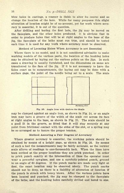
surface gage, the point <strong>of</strong> the needle being set to a scale. The scale<br />
<strong>Machinery</strong>, N. Y.<br />
Fig. 25. Angle Iron -with Groove for Scale<br />
may be clamped against an angle iron, as shown in Fig. 24, or an angle<br />
iron may have a groove <strong>of</strong> the width <strong>of</strong> the scale cut across its face<br />
at right angles to the base, as shown in Fig. 25. The scale should be<br />
a good fit in the groove, so fitted that it will stay securely at any<br />
point from frictional contact with the sides <strong>of</strong> the slot, or a spring may<br />
be so arranged as to insure the proper tension.<br />
Method Assuring- a Fair Degree <strong>of</strong> Accuracy<br />
Where greater accuracy is essential, the working points should be<br />
obtained by means <strong>of</strong> a height gage, as shown in Fig. 26. By means<br />
<strong>of</strong> such a tool the measurements may be fairly accurate, as the vernier<br />
scale allows <strong>of</strong> readings to one-thousandth inch. When the lines have<br />
been scribed at the proper locations they are prick punched. In order<br />
to prick punch exactly at the intersection <strong>of</strong> lines the operator must<br />
wear a powerful eye-glass, and use a carefully pointed punch, ground<br />
to an angle <strong>of</strong> 60 degrees. If the punch marks are made very light at<br />
first, the exact location may be observed nicely. The punch marks<br />
should not be deep, as there is a liability <strong>of</strong> alteration <strong>of</strong> location if<br />
the punch is struck with heavy blows. After the various points have<br />
been located and punched, the jig may be clamped to the face-plate<br />
<strong>of</strong> the lathe, and the bushing holes carefully drilled and bored to size.