Drill Jigs Principles of Design Machinery ... - Evenfall Studios
Drill Jigs Principles of Design Machinery ... - Evenfall Studios
Drill Jigs Principles of Design Machinery ... - Evenfall Studios

You also want an ePaper? Increase the reach of your titles
YUMPU automatically turns print PDFs into web optimized ePapers that Google loves.
24 No. sDRILL JIGS<br />
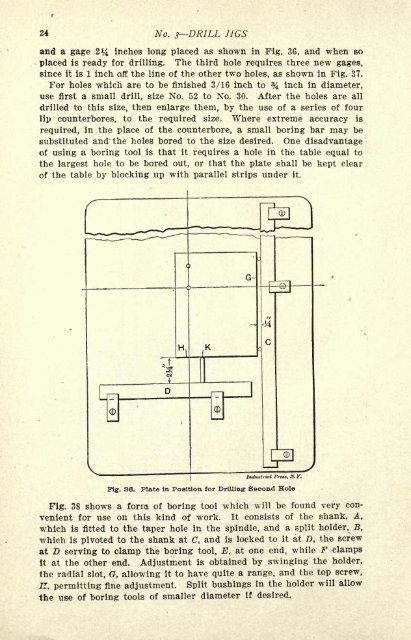
and a gage 2^ inches long placed as shown in Fig. 36, and when so<br />
placed is ready for drilling. The third hole requires three new gages,<br />
since it is 1 inch <strong>of</strong>f the line <strong>of</strong> the other two holes, as shown in Fig. 37.<br />
For holes which are to be finished 3/16 inch to % inch in diameter,<br />
use first a small drill, size No. 52 to No. 30. After the holes are all<br />
drilled to this size, then enlarge them, by the use <strong>of</strong> a series <strong>of</strong> four<br />
lip counterbores, to the required size. Where extreme accuracy is<br />
required, in the place <strong>of</strong> the counterbore, a small boring bar may be<br />
substituted and the holes bored to the size desired. One disadvantage<br />
<strong>of</strong> using a boring tool is that it requires a hole in the table equal to<br />
the largest hole to be bored out, or that the plate shall be kept clear<br />
<strong>of</strong> the table by blocking up with parallel strips under it.<br />
G-<br />
Induttrial /'/, N.Y.<br />
Fig. 36. Plate in Position for <strong>Drill</strong>ing- Second Hole<br />
Fig. 38 shows a form <strong>of</strong> boring tool which will be found very convenient<br />
for use on this kind <strong>of</strong> work. It consists <strong>of</strong> the shank, A,<br />
which is fitted to the taper hole in the spindle, and a split holder, B,<br />
which is pivoted to the shank at C, and is locked to it at D, the screw<br />
at D serving to clamp the boring tool, E, at one end, while F clamps<br />
It at the other end. Adjustment is obtained by swinging the holder,<br />
the radial slot, G, allowing it to have quite a range, and the top screw,<br />
IT, permitting fine adjustment. Split bushings in the holder will allow<br />
the use <strong>of</strong> boring tools <strong>of</strong> smaller diameter if desired.