Space Passive Hydrogen Maser - Performances and ... - Spectratime
Space Passive Hydrogen Maser - Performances and ... - Spectratime
Space Passive Hydrogen Maser - Performances and ... - Spectratime

Create successful ePaper yourself
Turn your PDF publications into a flip-book with our unique Google optimized e-Paper software.
<strong>Space</strong> <strong>Passive</strong> <strong>Hydrogen</strong> <strong>Maser</strong><br />
- <strong>Performances</strong> <strong>and</strong> lifetime data-<br />
Fabien Droz, Pierre Mosset, Qinghua Wang, Pascal<br />
Rochat,<br />
SpectraTime<br />
Neuchâtel, Switerl<strong>and</strong><br />
mail@spectratime.com<br />
Abstract—Galileo navigation program is in progress under the<br />
technical supervision of the European <strong>Space</strong> Agency (ESA). The<br />
preliminary activities related to GSTBV2 experimental satellite<br />
provide the first results <strong>and</strong> the implementation of the In Orbit<br />
Validation (IOV) phase are in progress. Atomic clocks represent<br />
critical equipment for the satellite navigation system <strong>and</strong> clocks<br />
development has been continuously supported by ESA. The<br />
Rubidium Atomic Frequency St<strong>and</strong>ard (RAFS) <strong>and</strong> the <strong>Passive</strong><br />
<strong>Hydrogen</strong> <strong>Maser</strong> (PHM) are at present the baseline clock<br />
technologies for the Galileo navigation payload. For the PHM,<br />
initial ground technological project related to lifetime possible<br />
limitation of the clock was initiated in parallel to satellite<br />
experimentation (GIOVE-B). Long duration frequency stability<br />
performance tests were recorded on ground demonstrating<br />
2*10 -15 clock stability at one day (including the drift). This<br />
article gives an overview on the ground lifetime data <strong>and</strong><br />
performance of the PHM. Extrapolation for the 12 years Galileo<br />
mission duration is discussed.<br />
I. INTRODUCTION<br />
GALILEO is a joint initiative of the European<br />
Commission <strong>and</strong> the European <strong>Space</strong> Agency (ESA) for a<br />
state-of-the-art global navigation satellite system, providing a<br />
highly accurate, guaranteed global positioning service under<br />
civilian control. It will probably be inter-operable with GPS<br />
<strong>and</strong> GLONASS, the two other Global Navigation Satellite<br />
Systems (GNSS) available today.<br />
The fully deployed Galileo system consists of 30 satellites<br />
(27 operational <strong>and</strong> 3 active spares), stationed on three circular<br />
Medium Earth Orbits (MEO) at an altitude of 23 222 km with<br />
an inclination of 56º to the equator.<br />
Atomic clocks represent critical equipment for the satellite<br />
navigation system. The Rubidium Atomic Frequency St<strong>and</strong>ard<br />
(RAFS) <strong>and</strong> <strong>Passive</strong> <strong>Hydrogen</strong> <strong>Maser</strong> (PHM) are at present<br />
the baseline clock technologies for the Galileo navigation<br />
payload. According to the present baseline, every satellite will<br />
embark two RAFS's <strong>and</strong> two PHM's. The adoption of a "dual<br />
978-1-4244-3510-4/09/$25.00 ©2009 IEEE 393<br />
II.<br />
Marco Belloni, Marina Gioia<br />
Selex Galileo<br />
Milan, Italy<br />
Alberto Resti, Pierre Waller<br />
European <strong>Space</strong> Agency (ESTEC)<br />
Nordwijk, Netherl<strong>and</strong>s<br />
technology" for the on-board clocks is dictated by the need to<br />
insure a sufficient degree of reliability (technology diversity)<br />
<strong>and</strong> to comply with the Galileo lifetime requirement (12<br />
years).<br />
The activities related to Galileo System Test Bed (GIOVE<br />
satellites) experimental satellite as well as the implementation<br />
of the In Orbit Validation phase are in progress [1]. The first<br />
experimental satellite (GIOVE-A) was launched 28 th<br />
December 2005, to secure the Galileo frequency fillings, to<br />
test some of the critical technologies, such as the atomic<br />
clocks, to make experimentation on Galileo signals <strong>and</strong> to<br />
characterise the MEO environment. There is two RAFS on the<br />
GIOVE-A satellite supplied by Surrey Satellite Technologies<br />
Ltd. The second experimental satellite (GIOVE-B) was<br />
launched 27 th April 2008, <strong>and</strong> provide a more representative<br />
payload including the one PHM in addition to two RAFS.<br />
GIOVE-B satellite was supplied by Astrium. The four In Orbit<br />
Validation satellites are to be launched within the next two<br />
years.<br />
DEVELOPMENT & QUALIFICATION ACTIVITIES OF<br />
PASSIVE HYDROGEN MASER<br />
The first maser development activity tailored to navigation<br />
applications was kicked off in 1998. It was initiated by the<br />
development of an active maser at Observatory of Neuchâtel<br />
(ON). However, at the Galileo definition phase, it became<br />
clear that the accommodation of the active maser on the<br />
satellite was too penalizing in term of mass <strong>and</strong> volume, <strong>and</strong><br />
the excellent frequency stability performances of the active<br />
maser were not required. In 2000 it was re-orientated towards<br />
the development of a PHM based on heritage on active masers<br />
studies.<br />
The development of the EM was completed at the<br />
beginning of 2003, under the lead of ON with Selex Galileo<br />
(SG) (former Galileo Avionica) subcontractor for the<br />
electronics package <strong>and</strong> SpectraTime (SpT) (former Temex
Neuchâtel Time) supporting the activity in view of the future<br />
PHM industrialisation. The instrument has been under<br />
continuous test for two years highlighting potential lifetime<br />
technological problems <strong>and</strong> performance limitations.<br />
The industrialization activity aimed at PHM design<br />
consolidation for future flight qualification <strong>and</strong> production<br />
was started in January 2003. The industrial consortium was<br />
led by SG designing the electronics package <strong>and</strong> responsible<br />
for the integration of the whole instrument, with SpT<br />
responsible for the manufacturing of the physical package.<br />
The overall structure of the instrument was reviewed to<br />
increase compactness <strong>and</strong> to ease the Assembly, Integration<br />
<strong>and</strong> Test process on the satellite by the inclusion of an external<br />
vacuum envelope. The weak technological elements were<br />
fully redesigned too. Main efforts in the industrialization<br />
frame were focused on the definition of repeatable <strong>and</strong> reliable<br />
manufacturing processes <strong>and</strong> fixtures, particularly for the<br />
physical package:<br />
• Teflonization of the quartz storage Bulb<br />
• <strong>Hydrogen</strong> beam assembly<br />
• Getters assembly<br />
• Tuning of the microwave cavity<br />
• H2 purifier assembly<br />
• Magnetic shield assembly<br />
• State selector assembly<br />
• <strong>Hydrogen</strong> supply <strong>and</strong> dissociator<br />
<strong>and</strong> for the electronic package <strong>and</strong> the whole Instrument:<br />
• Reduction of PHM volume <strong>and</strong> footprint<br />
• Improvement of TM/TC interface<br />
• Ground operability at ambient pressure<br />
• Redesign of hydrogen dissociator<br />
• Improvement of thermal <strong>and</strong> pressure controls<br />
• Redesign of PHM <strong>and</strong> Purifier supply<br />
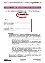
A technological model (Fig. 1), a Structural Model <strong>and</strong> an<br />
EQM were built for these objectives <strong>and</strong> to qualify the new<br />
upgraded design. In addition, four QMs for life demonstration<br />
are being manufactured <strong>and</strong> two of them are submitted to<br />
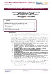
prolonged testing. In the frame of GSTB-V2, one PFM (Fig.<br />
2) has passed the proto-qualification testing <strong>and</strong> was delivered<br />
together one other FM (i.e. Flight Spare, FS). The PFM <strong>and</strong><br />
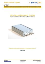
FS were delivered in mid-2005. Fig. 3 shows the improvement<br />
of the frequency stability performances observed along the<br />
GSTB-V2 models as resulting of the manufacturing process<br />
refining <strong>and</strong> consolidation of the alignment procedures. The<br />
FS is now operating on board of GIOVE-B since 1 year [2, 3].<br />
394<br />
1.00E-13<br />
1.00E-14<br />
1.00E-15<br />
Figure 1. Technological model<br />
Figure 2. Picture of PHM PFM<br />
ADEV GSTBV2-Production<br />
1.00E-12<br />
10 100 1000 10000<br />
Averanging Time<br />
EQM PFM FS GSTBV2 Requirement<br />
Figure 3. Allan Deviation for the GSTB-V2 models
III. PASSIVE HYDROGEN MASER ACTIVITIES FOR THE IN<br />
ORBIT VALIDATION<br />
The IOV (In Orbit Validation) contract was signed in<br />
2006. The scope of this Programme was the production <strong>and</strong><br />
delivery of 8 Flight Units to be embarked on the first 4<br />
satellites of the Galileo Constellation.<br />
This contract has represented a new development phase for<br />
the PHM at sub-Unit level (i.e. Physic Package <strong>and</strong> Electronic<br />
Package) <strong>and</strong> Instrument level. Due to the changing of the<br />
environment <strong>and</strong> operating constraints with respect to GSTB-<br />
V2, strong efforts have been put in place in order to further<br />
improve both the PHM performances <strong>and</strong> the manufacturing<br />
processes. In particular:<br />
• Increasing of the hydrogen storage capability<br />
• Increasing of the storage temperature capability<br />
• Extension of the storage time without maintenance<br />
• Refining of the Physic Package manufacturing<br />
processes<br />
• Improvement of the start-up logic in order to avoid<br />
any telecomm<strong>and</strong> intervention<br />
• Improvement of the PHM environmental sensitivity<br />
• Improvement of the EMC robustness<br />
• Improvement of the TT&C interface<br />
• Refining of the electronic design in order to<br />
simplify the tuning <strong>and</strong> improve its reliability<br />
An EQM has been successfully qualified against the new<br />
Galileo requirements in April 2008 <strong>and</strong> 6 Flight Units were<br />
produced <strong>and</strong> tested in December 2008, demonstrating a<br />
production rate capability near to 1 PHM per month with<br />
potential improvement margins.<br />
The very good performance repeatability observed along<br />
the IOV production is illustrated in Fig. 4.<br />
1.00E-13<br />
1.00E-14<br />
1.00E-15<br />
ADEV IOV-Production<br />
1.00E-12<br />
10 100 1000 10000 100000<br />
Figure 4.<br />
Averanging Time<br />
EQM PFM FM2 FM3 FM4 FM5 FM6 IOV Requirement<br />
Allan Deviation for the IOV models with frequency drift included<br />
395<br />
IV. LIFETIME EXTRAPOLATION FROM GROUND TESTING<br />
In the frame of the “Lifetime Qualification of PHM”, two<br />
PHM QMs are contributed to the test under vacuum in order<br />
to perform the monitoring of the potential lifetime limitations<br />
of the PHM.<br />
The test bench is composed of two identical units <strong>and</strong><br />
some common elements.<br />
The two identical units consist of:<br />
• the vacuum chamber with pumping system <strong>and</strong> gauge<br />
• the base-plate connected with cooling system<br />
• the frequency stability measurement system:<br />
Picotime measuring independently each unit<br />
• the telemetry (TM) interface box<br />
• the data acquisition system for additional TM<br />
• the PC with automatic control <strong>and</strong> acquisition system<br />
• the power supply <strong>and</strong> UPS<br />
The common elements are:<br />
• the QM life time test equipment, i.e. the manmachine-interface<br />
support including serial<br />
telecomm<strong>and</strong> (TC) generation <strong>and</strong> main serial TM<br />
recording for both units<br />
• the reference frequency system; H-<strong>Maser</strong> with GPS<br />
monitoring <strong>and</strong> the frequency distribution unit<br />
(common for all the SpT facilities)<br />
The overall layout of the test bench is illustrated in Fig. 5.<br />
Most of the parts are off-the-shelf st<strong>and</strong>ard parts.<br />
Figure 5. PHM QM Lifetime test bench<br />
A total period of about 18 months of continuous<br />
measurement for each QM is required. One has been<br />
submitted to the life time test for 9 months <strong>and</strong> the other one<br />
to 1 year, respectively.<br />
In addition to frequency stability performances, more than<br />
20 parameters are measured:<br />
• Atomic signal amplitude<br />
• Cavity varactor voltage<br />
• USO varactor voltage<br />
• <strong>Hydrogen</strong> supply pressure <strong>and</strong> temperature
• <strong>Hydrogen</strong> dissociation oscillator voltage <strong>and</strong> current<br />
• Dissociator optical sensor voltage<br />
• Purifier supply setting voltage<br />
• 10 MHz output level<br />
• Cavity setting temperature<br />
• PHM current (main bus)<br />
• C-Field Current<br />
• Ion pump voltage <strong>and</strong> current<br />
• Cavity temperature<br />
• Thermal plate temperature<br />
• Vaccum container temperature<br />
• Temperature sensor PP/EP interface<br />
• Temperature sensor Thermal Plate/PHM interface<br />
Most of them, do not present measurable ageing effects.<br />
The ones which are discussed below are the more relevant or<br />
affected by long term operation. Three typical records on<br />
QM1 (used as reference for this paper) are shown in Fig. 6.<br />
Cavity Varactor Voltage [V]<br />
<strong>Hydrogen</strong> Supply Temperature [°C]<br />
Atomic Signal Amplitude [V]<br />
4.0<br />
3.5<br />
3.0<br />
2.5<br />
2.0<br />
1.5<br />
1.0<br />
39.0<br />
38.5<br />
38.0<br />
37.5<br />
37.0<br />
36.5<br />
36.0<br />
10<br />
8<br />
6<br />
4<br />
2<br />
0<br />
0<br />
0<br />
0<br />
50<br />
50<br />
50<br />
100<br />
100<br />
100<br />
150<br />
Day<br />
150<br />
Day<br />
Exponential Fit:<br />
fit = A+B*exp(-C*x)<br />
A = 0.71357 ± 0.000963<br />
B = 2.9696 ± 0.000416<br />
C = 0.0049197 ± 3.87e-06<br />
200<br />
Square Root Fit:<br />
fit = A+B*x^0.5<br />
A = 35.618 ± 0.000742<br />
B = 0.22548 ± 5.57e-05<br />
200<br />
250<br />
Transition periodes after switch-on removed<br />
150<br />
Day<br />
Figure 6. Nine months typical TMs (cavity varactor voltage, hydrogen<br />
supply temperature, <strong>and</strong> atomic signal amplitude) on QM1 lifetime test<br />
200<br />
250<br />
250<br />
396<br />
The self frequency drifting of the microwave cavity used<br />
to amplify the atomic signal is highlighted by the varactor<br />
voltage variation over the time. This varactor maintains the<br />
overall microwave frequency centered to the atomic line<br />
(Automatic Cavity Tuning). For the cavity varactor voltage,<br />
the best fitting corresponds to an exponential function of time,<br />
which has been also demonstrated during the PHM physics<br />
package final test.<br />
Another key element is the <strong>Hydrogen</strong> consumption over<br />
the time. About 25 bar*liter of <strong>Hydrogen</strong> are stored within a<br />
tank filled with hydride. By the use of the hydride, it is<br />
possible to store the 25 bar*liter within a volume as low as 0.1<br />
liter with internal pressure below 5 bars at around 35°C<br />
temperature. During the life of the instrument, the hydrogen is<br />
consumed <strong>and</strong> the tank temperature must be increased in order<br />
to maintain the internal pressure constant. So, the temperature<br />
variation over the time is a good indication of the consumed<br />
<strong>Hydrogen</strong>. It has been observed that container temperature<br />
increasing rate is higher during first few weeks after switchon,<br />
due to the solid-state hydride transition phase. This<br />
transition periods after switch-on were removed to evaluate<br />
the whole evolution of this parameter.<br />
As most relevant parameter of what happen within the<br />
PHM is the atomic signal amplitude. The amplitude is<br />
sensitive to any degradation as internal coating, outgasing,<br />
leakage, dissociation efficiency, quality factor of the<br />
microwave cavity, interrogation power instability, receiver<br />
electronic degradation, temperature instability, … So, it is of<br />
primary importance to verify that the atomic signal amplitude<br />
do not decay over the life time below a reasonable limit.<br />
Considering the measured curve, the expected behavior is<br />
very well confirmed as no noticeable ageing effect generates<br />
change in the atomic signal amplitude.<br />
For the two remaining parameters, extrapolations for 12<br />
years were performed, illustrated in Fig. 7 (QM1). The red<br />
curve is the measurement data during 9 months, <strong>and</strong> the blue<br />
line with dot markers is the extrapolation according to the<br />
fitting formula.<br />
Table I provides the summary of these key parameters<br />
predicted evolution for QM1 submitted to life testing.<br />
For the cavity varactor voltage, the predicted value is still<br />
within the adjustable frequency tuning range. Moreover, the<br />
decaying of this parameter could be compensated by<br />
increasing the cavity temperature by very small step of few<br />
m°C. Such implementation has been demonstrated by SG,<br />
without impacting on the PHM frequency stability.<br />
For the hydrogen supply, the temperature in 12 years is<br />
about 50°C, which is in line with the expected H2<br />
consumption. In fact, for later QMs <strong>and</strong> IOV FMs, a new type<br />
of hydrogen supply container of higher purity LN5, with lower<br />
maximum pressure <strong>and</strong> more constant pressure plateau, has<br />
been applied. In the end of life the final temperature at<br />
constant pressure will be lower than the present one for QM1,<br />
which will allow a comfortable margin for the safety reason.
Cavity Varactor Voltage [V]<br />
<strong>Hydrogen</strong> Supply Temperature [°C]<br />
4<br />
3<br />
2<br />
1<br />
0<br />
50<br />
48<br />
46<br />
44<br />
42<br />
40<br />
38<br />
36<br />
0<br />
0<br />
1000<br />
1000<br />
Measurement<br />
Extrapolation<br />
Measurement<br />
Extrapolation<br />
2000<br />
Day<br />
2000<br />
Day<br />
3000<br />
3000<br />
Year exp<br />
1 1.207<br />
1.5 0.914<br />
2 0.795<br />
2.5 0.747<br />
3 0.727<br />
4 0.716<br />
5 0.714<br />
6 0.714<br />
7 0.714<br />
8 0.714<br />
9 0.714<br />
10 0.714<br />
11 0.714<br />
12 0.714<br />
4000<br />
Year sqt<br />
1 39.93<br />
1.5 40.89<br />
2 41.71<br />
2.5 42.43<br />
3 43.08<br />
4 44.23<br />
5 45.25<br />
6 46.17<br />
7 47.02<br />
8 47.80<br />
9 48.54<br />
10 49.24<br />
11 49.91<br />
12 50.54<br />
Figure 7. TMs (cavity varactor voltage <strong>and</strong> hydrogen supply temperature)<br />
on QM1 lifetime test with prediction on 12 years<br />
TABLE I. EXTRAPOLATION OF AGEING DATA IN 12 YEARS (QM1)<br />
4000<br />
TM Extrapolation in 12 years<br />
Cavity varactor votage 0.71V<br />
<strong>Hydrogen</strong> supply temperature 50.5°C<br />
The other important parameter, ion pump current is below<br />
1mA all over the period, which indicates the high vacuum<br />
better than 10 -7 mbar.<br />
The prediction demonstrates that no major impact on<br />
performances is foreseen for a lifetime of 12 years.<br />
Fig. 8 shows the QM1 frequency data <strong>and</strong> the frequency<br />
stability measured during recent last 3 months, the frequency<br />
drift was
VI. REFERENCES<br />
[1] P. Waller, F. Gonzalez, J. Hahn, S. Binda, R. Piriz, I. Hidalgo, et al.<br />
“In-orbit performance assessment of GIOVE clocks,” 40 th Annual<br />
Precise Time <strong>and</strong> Time Interval (PTTI) Systems <strong>and</strong> Applications<br />
Meeting Meeting, 1-4 Dec. 2008, Reston (USA), in press.<br />
[2] F.Droz, P.Mosset, G.Barmaverain, P.Rochat, Q.Wang, M.Belloni, et al.<br />
“The on-board Galileo clocks: Rubidium St<strong>and</strong>ard <strong>and</strong> <strong>Passive</strong><br />
398<br />
<strong>Hydrogen</strong> <strong>Maser</strong> current status <strong>and</strong> performance,” 20 th Europen<br />
Frequency <strong>and</strong> Time Foroum, 27-30 Mar. 2006, Braunschweig<br />
(German).<br />
[3] Q. Wang, P. Mosset, F. Droz, P. Rochat, <strong>and</strong> G. Busca, “Verification<br />
<strong>and</strong> optimization of the physics parameters of the onboard Galileo<br />
passive hydrogen maser,” Proceedings of 38th Precise Time <strong>and</strong> Time<br />
Interval (PTTI) Systems <strong>and</strong> Applications Meeting, 5-7 Dec. 2006,<br />
Reston (USA), pp 81-94.