ea-cT configuration Tool - System Sensor
ea-cT configuration Tool - System Sensor
ea-cT configuration Tool - System Sensor

Create successful ePaper yourself
Turn your PDF publications into a flip-book with our unique Google optimized e-Paper software.
inSTaLLaTiOn anD MainTenance inSTRu<strong>cT</strong>iOnS<br />
<strong>ea</strong>-<strong>cT</strong> <strong>configuration</strong> <strong>Tool</strong><br />
SPecificaTiOnS<br />
Dimensions: 1.3˝H×2.2˝W×7.7˝L<br />
(33mm H×56mm W×196mm L)<br />
Communication Range: 30 ft. (9.1 m)<br />
24 ft (7.3m) with dust cover on device<br />
Battery Life (2 AA, batteries not included): 168 hrs (typical usage)<br />
Storage Temperature Range: –4ºF to 140ºF (–20ºC to 60ºC)<br />
Operating Temperature Range: 32ºF to 122ºF (0ºC to 50ºC)<br />
PRODu<strong>cT</strong> DeScRiPTiOn<br />
The EA-CT is a hand-held remote control that is designed to communicate<br />
with Eclipse devices via infrared signals. The remote control will give the<br />
user the ability to communicate with the panel and other devices through any<br />
selected device on the loop. The EA-CT can r<strong>ea</strong>d device information such as<br />
type, loop, address and sensitivity along with write loop, address, branch , serial<br />
number and service date, and initiate walk test and device test. The EA-CT<br />
f<strong>ea</strong>tures a 16-character liquid crystal display and a 17-button keypad.<br />
GLOSSaRy<br />
Address: Loop and address are the two components of a device’s identifier<br />
in an Eclipse system. Addresses 1 to 254 are valid for detectors and modules.<br />
Branch: For loops that use t-taps or star-taps, a branch number can be specified<br />
on <strong>ea</strong>ch device after the tap to indicate which device will be programmed<br />
first in a system with auto-addressing. The branch number can be from 1 to<br />
255.<br />
Deselect: If a user decides not to communicate to a device that has been selected,<br />
it may be deselected and another device chosen inst<strong>ea</strong>d.<br />
Loop: Loop and address are the two components of a device’s identifier in an<br />
Eclipse system. With Eclipse, multiple loops may reside on the same pair of<br />
wires. Loops can be numbered 1 to 254.<br />
Master Key: If a user misplaces their PIN number, the EA-CT can generate a<br />
code or master key that will allow technical support to provide a temporary<br />
PIN number for access.<br />
NO COMM.RETRY?: This message will app<strong>ea</strong>r on the <strong>configuration</strong> tool<br />
screen if the message was not transmitted properly to the receiving device.<br />
Rep<strong>ea</strong>t the steps to complete the desired action.<br />
PIN number: The EA-CT is equipped with a personal identification number<br />
that, when enabled, prevents unauthorized use of the device.<br />
Select: Since the EA-CT can conceivably have more than one detector<br />
or module within its field of view, only one device can be chosen or<br />
“selected” from the group. The select key is used to choose the device<br />
to which the EA-CT will communicate. Pressing the SELECT key more than<br />
once will alternately select <strong>ea</strong>ch device within the EA-CT range. A selected<br />
device is r<strong>ea</strong>dy to receive communications from the EA-CT.<br />
Target: The target is the address of the device that you would like to communicate<br />
with using the EA-CT. The target is not necessarily the device that is<br />
selected or a device in the line of sight.<br />
GeneRaL inSTRu<strong>cT</strong>iOn<br />
Press the PWR button on the EA-CT. For first time users or devices without<br />
a PIN number, the main menu will be displayed. To be able to set your PIN<br />
number, refer to the PIN enable/disable (7.1) section of this manual. The<br />
main menu consists of seven choices for the user. You can select <strong>ea</strong>ch choice<br />
by pressing the up or down keys to highlight your selection and pressing enter<br />
or by pressing the number of the selected item.<br />
NOTE: EA-CT automatically shuts down after 200 seconds of non-use.<br />
Before communication is enabled, the device must be “selected” by the EA-<br />
CT. To select a device, aim the EA-CT at the device and press the SELECT key.<br />
In situations where there is more than one device in close proximity, the de-<br />
sired device may not be initially selected. Simply press the SELECT key again<br />
and that device will be deselected and another device within the EA-CT field<br />
of view will be selected. To deselect a device, aim the EA-CT at the device and<br />
press the DESELECT key. A device can be selected or deselected at any time.<br />
When a device is selected by the EA-CT, the LED on the device will change<br />
to a blinking green pattern. This will help the user ensure the correct Eclipse<br />
device is selected. The only exception is the mini monitor module. This unit’s<br />
LED will temporarily turn off because it does not have a bi-color LED.<br />
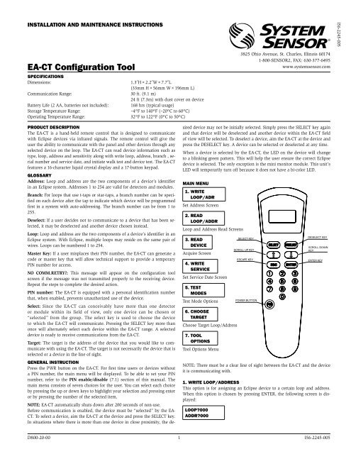
Main Menu<br />
1. WRiTe<br />
LOOP/aDR<br />
Set Address Screen<br />
2. R<strong>ea</strong>D<br />
LOOP/aDDR<br />
Loop and Address R<strong>ea</strong>d Screens<br />
3. R<strong>ea</strong>D<br />
Device<br />
Acquire Screen<br />
4. WRiTe<br />
SeRvice<br />
Set Service Date Screen<br />
5. TeST<br />
MODeS<br />
Test Mode Options<br />
6. cHOOSe<br />
TaRGeT<br />
Choose Target Loop/Address<br />
7. TOOL<br />
OPTiOnS<br />
<strong>Tool</strong> Options Menu<br />
NOTE: There must be a cl<strong>ea</strong>r line of sight between the EA-CT and the device<br />
it is communicating with.<br />
1. WRiTe LOOP/aDDReSS<br />
This option is for assigning an Eclipse device to a certain loop and address.<br />
When this option is chosen by pressing ENTER, the following screen is displayed:<br />
LOOP?000<br />
aDDR?000<br />
3825 Ohio Avenue, St. Charles, Illinois 60174<br />
1-800-SENSOR2, FAX: 630-377-6495<br />
www.systemsensor.com<br />
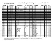
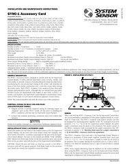
SELECT KEY<br />
SCROLL UP KEY<br />
ESCAPE KEY<br />
POWER BUTTON<br />
DESELECT KEY<br />
SCROLL DOWN<br />
KEY<br />
D800-20-00 1 I56-2245-005<br />
ENTER KEY<br />
I56-2245-005
The user may then enter the specific address and loop designation desired for<br />
that device. The maximum address and loop numbers that can be used are<br />
254. After an address is entered, point the EA-CT to the device whose address<br />
you wish to set. Press the SELECT key to select that device. When the ENTER<br />
key is pressed, the device will start a communication. If there is a problem<br />
with the communication a trouble screen will be displayed:<br />
nO cOMM.<br />
ReTRy?<br />
To retry, press the ENTER key again and the EA-CT will attempt to re-connect<br />
to the device. If the address is accepted, the following screen will be displayed:<br />
OK neW<br />
aDDR. SeT<br />
At this point if the user wishes to incr<strong>ea</strong>se the address number, the up arrow should<br />
be pressed, and the following screen will app<strong>ea</strong>r with the address incremented:<br />
LOOP?000<br />
aDDR?000<br />
If at this point the user selects another unit using the SELECT button, by<br />
pressing ENTER the incremented address and the same loop will be recorded<br />
on the new unit.<br />
The same functionality is available by using the down arrow.<br />
2. R<strong>ea</strong>D LOOP/aDDR<br />
Pressing ENTER at this menu option will give the user the ability to r<strong>ea</strong>d a<br />
selected Eclipse device to see what its current address and loop designation<br />
is. When this choice is made, the screen will prompt the user to point to the<br />
device that is to be r<strong>ea</strong>d. Point to the device that you want to r<strong>ea</strong>d and press<br />
the ENTER key. If the communication is successful, the screen will display<br />
something similar to the following example:<br />
LOOP: 147<br />
aDDR: 123<br />
If there is a problem with the communication, trouble screen is received:<br />
nO cOMM.<br />
ReTRy?<br />
To retry, press the enter key again and the EA-CT will attempt to communicate<br />
again to the device.<br />
3. R<strong>ea</strong>D Device<br />
This menu option will indicate, for a selected device, its type, address, loop,<br />
and branch marker. When ENTER is pressed on this option, the first screen<br />
that comes up, is similar to:<br />
LOOP: 147<br />
aDDR: 123<br />
If that is not the correct loop or address, the user can press ESC to go back to<br />
the Address Set Screen to make the change. If that is the correct setting and<br />
the selected device is a device with isolators, the down arrow key is pressed to<br />
show the branch setting similar to the example:<br />
BRancH#<br />
iS:xxx<br />
If that is not the correct branch number, the user can go to the Branch Setting<br />
screen by pressing enter again to make the appropriate changes.<br />
SeT BRancH #<br />
To set a branch marker on a selected device, press the enter key on this option,<br />
and after the set new branch screen is displayed the following screen<br />
will come up:<br />
BRancH #<br />
?xxx<br />
Enter the branch number that is desired. Point the EA-CT at the device that<br />
is to receive the branch marker. Press enter and, after a moment, the EA-CT<br />
will display:<br />
BRancH<br />
nuM. set<br />
To display the new branch number press ESC twice<br />
BRancH #<br />
iS: xxx<br />
NOTE: If the selected device does not contain isolators the following serial<br />
number screen will app<strong>ea</strong>r immediately following the loop and address view.<br />
Sno. 0xxx<br />
xxxxxxxx<br />
The next screen that comes up will depend on the device type.<br />
If the device is a h<strong>ea</strong>t detector the following display will app<strong>ea</strong>r:<br />
H<strong>ea</strong>T<br />
DeTe<strong>cT</strong>OR<br />
If the device is a h<strong>ea</strong>t detector, the user can press the down key again to find<br />
out whether the device is set at a rate-of-rise or a fixed temperature setting.<br />
If the detector is configured to be a rate-of-rise detector, the following screen<br />
will app<strong>ea</strong>r:<br />
aLaRMS:<br />
ROfRiSe<br />
If the detector is configured at a fixed h<strong>ea</strong>t temperature setting and is on the<br />
US menu setting, the following screen will app<strong>ea</strong>r:<br />
S1:xxx ºf<br />
S2:xxx ºf<br />
If the detector is configured at a fixed h<strong>ea</strong>t temperature setting and is on the<br />
Non-US menu setting, the following screen will app<strong>ea</strong>r:<br />
S1:xxx ºc<br />
S2:xxx ºc<br />
If the device is a photo-h<strong>ea</strong>t detector, the following screen will app<strong>ea</strong>r:<br />
Photo-HT<br />
Detector<br />
If the down arrow is pressed again, a screen similar to this one will show whether<br />
the device is configured to Acclimate.<br />
aHiS: 0.5<br />
aLOS: 4.0<br />
This screen shows the sensitivity level of the photo-h<strong>ea</strong>t detector. The AHIS<br />
is the upper limit of the Acclimate sensitivity range in percent per foot. The<br />
ALOS indicates the lower limit of the Acclimate sensitivity range in percent<br />
per foot. Detector sensitivity cannot be changed using the EA-CT. Pl<strong>ea</strong>se refer<br />
to the control panel installation manual to change the levels of sensitivity on<br />
the detector. If the down arrow is pressed again a screen similar to this one<br />
will app<strong>ea</strong>r:<br />
SenS. fe<br />
LeveL: 2.4<br />
The “FE” app<strong>ea</strong>rs only if the detector has a flame enhancement f<strong>ea</strong>ture and<br />
that f<strong>ea</strong>ture is currently enabled. The second line indicates what the detector’s<br />
exact sensitivity is at that moment.<br />
If the device is not configured to Acclimate the following screen similar to this<br />
one will app<strong>ea</strong>r:<br />
S1:xxx<br />
S2:xxx<br />
This shows the sensitivity level corresponding to the sensitivity broadcasts.<br />
Pressing the down arrow again will show how dirty the detector is. This is<br />
indicated as the percentage of drift compensation limit used. Pl<strong>ea</strong>se refer to<br />
the control panel installation manual for the percentage that requires cl<strong>ea</strong>ning.<br />
D800-20-00 2 I56-2245-005
% DiRTy<br />
0000<br />
If the device is a photo-duct detector, the following screen will app<strong>ea</strong>r:<br />
PHO-Du<strong>cT</strong><br />
DeTe<strong>cT</strong>OR<br />
If the down arrow is pressed again, a screen similar to this one will app<strong>ea</strong>r:<br />
S1:xxx<br />
S2:xxx<br />
This screen shows the levels of sensitivity for the selected device. Pressing the<br />
down arrow again will show how dirty the detector is. This is indicated as the<br />
percentage of drift compensation limit used. Pl<strong>ea</strong>se refer to the control panel<br />
installation manual for the percentage that requires cl<strong>ea</strong>ning.<br />
If the device is a photo detector, the following screen will app<strong>ea</strong>r:<br />
PhotoD<strong>cT</strong><br />
Detector<br />
If the down arrow is pressed again, a screen similar to this one will show up if<br />
the device is configured to Acclimate.<br />
aHiS: 0.5<br />
aLOS: 4.0<br />
This screen shows the Acclimate sensitivity range of the photo detector. The<br />
AHIS is the upper limit of the sensitivity range in percent per foot. The ALOS<br />
indicates the lower limit of the sensitivity range in percent per foot. Detector<br />
sensitivity cannot be changed using the EA-CT. Pl<strong>ea</strong>se refer to the control<br />
panel installation manual to change the levels of sensitivity on the detector.<br />
If the down arrow is pressed again a screen similar to this one will app<strong>ea</strong>r:<br />
SenS<br />
LeveL: 2.4<br />
If the device is not configured to Acclimate the following screen similar to this<br />
one will app<strong>ea</strong>r:<br />
S1:xxx<br />
S2:xxx<br />
This shows the sensitivity level corresponding to the sensitivity broadcasts.<br />
Pressing the down arrow again will show the how dirty the detector is. This<br />
is indicated as the percentage of drift compensation limit used. Pl<strong>ea</strong>se refer to<br />
the control panel installation manual for the percentage that requires cl<strong>ea</strong>ning.<br />
If the device is an Ion detector, the following screen will app<strong>ea</strong>r:<br />
iOn Se<br />
DeTe<strong>cT</strong>OR<br />
If the down arrow is pressed again, a screen simliar to this one will show up if<br />
the device is configured to Acclimate:<br />
aHiS.x.x%<br />
xxMic<br />
If the down arrow is pressed again, a screen simliar to this one will show up:<br />
aLOS x.x%<br />
xxMic<br />
If the down arrow is pressed again, a screen similar to this one will app<strong>ea</strong>r:<br />
SenS x.x%<br />
xxMic<br />
If the device is not configured to Acclimate a screen similar to this one will app<strong>ea</strong>r:<br />
S1: x.x%<br />
xxMic<br />
Optionally “SE” will app<strong>ea</strong>r if smoldering is enabled<br />
Reporting the Acclimate Hi sensitivity<br />
Reporting the Acclimate Low sensitivity<br />
Showing the current detector’s sensitivity<br />
If the down arrow is pressed again, a screen similar to this one will app<strong>ea</strong>r:<br />
S2: x.x%<br />
xxMic<br />
This shows the sensitivity level corresponding to the sensitivity broadcasts.<br />
Pressing the down arrow again will show how dirty the detector is. This is<br />
indicated as the percentage of drift compensation limit used. Pl<strong>ea</strong>se refer to<br />
the control panel installation manual for the percentage that requires cl<strong>ea</strong>ning.<br />
If the device is a control module, the following screen will app<strong>ea</strong>r:<br />
cOnTROL<br />
MODuLe<br />
If the device is a relay module, the following screen will app<strong>ea</strong>r:<br />
ReLay<br />
MODuLe<br />
If the device is a monitor module, the following screen will app<strong>ea</strong>r:<br />
MOniTOR<br />
MODuLe<br />
If the device is mini module, the following screen will app<strong>ea</strong>r:<br />
Mini<br />
MODuLe<br />
If the device is a pull station, the following screen will app<strong>ea</strong>r:<br />
PuLL<br />
STaTiOn<br />
If the device is conventional zone module, the following screen will app<strong>ea</strong>r:<br />
cOnv ZOn<br />
MODuLe<br />
If the device is dual monitor module, the following screen will app<strong>ea</strong>r:<br />
DuaL MOn<br />
MODuLe<br />
When the down arrow is pressed again on all ECLIPSE devices the screen will<br />
show the date when <strong>ea</strong>ch device was last serviced (if the service data was<br />
set during the last service). If the Menu Settings are set to US format the date<br />
format will be MM/DD/YY. If the settings are Non-US setting the date will be<br />
displayed as DD/MM/YY.<br />
SeRviceD<br />
07/16/12<br />
When the down arrow is pressed again on all devices, the display will show the<br />
date the device was manufactured in weeks of the y<strong>ea</strong>r followed by the y<strong>ea</strong>r.<br />
Manuf.:<br />
WK: 02,11<br />
4. WRiTe SeRvice<br />
This setting allows a service technician to record when the selected Eclipse device<br />
has been serviced. When this choice is made, the EA-CT will request the<br />
user to point to the selected device, and if the communication is successful, a<br />
screen similar to the following is displayed:<br />
SeRviceD:<br />
10/10/95<br />
NOTE: The service date is automatically entered as the current date and cannot<br />
be changed to a different day.<br />
5. TeST MODeS<br />
5.1 TeST aLaRM<br />
This option will cause a device to self-test. Point to the selected device that requires<br />
testing and press enter. When the communication is complete, a screen<br />
similar to this will be displayed:<br />
OK aLaRM TeST SeT<br />
D800-20-00 3 I56-2245-005
5.2 exiT aLaRM<br />
Pressing enter on this choice will end the test on the given device. Point to the<br />
selected device whose alarm is to be cl<strong>ea</strong>red. If the communication is successful<br />
and the test is ended the following screen will app<strong>ea</strong>r:<br />
OK aLaRM<br />
TeST cLR<br />
6. cHOOSe TaRGeT<br />
This option is for communicating with devices that cannot be seen in the line<br />
of sight of the EA-CT such as those mounted above the ceiling or below the<br />
floor. Begin by selecting a device within the line of sight. The out of sight<br />
device will be able to communicate through that SELECTED device. When this<br />
option is selected, the following screen is displayed:<br />
LOOP?000<br />
aDDR?000<br />
Enter the specific address of the device with which communication is desired<br />
and press the enter key. The user will then proceed to the main menu and<br />
perform r<strong>ea</strong>d/write options.<br />
7. TOOL OPTiOnS<br />
The user can scroll through the different choices of the options menu by using<br />
the arrow keys.<br />
7.1 Pin<br />
en./DiS.<br />
This option enables or disables the PIN number function. When ENTER is<br />
pressed the following screen app<strong>ea</strong>rs:<br />
enaBLe<br />
*DiSaBLe<br />
The asterisk points to the setting currently selected. Use either of the arrow<br />
keys to move the asterisk to the desired option and press ENTER. If the asterisk<br />
moves to the Enable line, then the PIN number is enabled.<br />
NOTE: If the wrong PIN number is entered upon power-up, the EA-CT will<br />
automatically shut off.<br />
7.2 Pin<br />
cHanGe<br />
This option is used to enter or change the PIN number. When this is selected<br />
the following screen comes up:<br />
?Pin#<br />
xxxx<br />
The user types the desired PIN number and presses the enter key. The new<br />
PIN number is activated.<br />
NOTE: Any PIN number entered here supersedes any previous PIN number<br />
that was being used.<br />
<strong>System</strong> <strong>Sensor</strong> warrants its enclosed product to be free from defects in materials and<br />
workmanship under normal use and service for a period of three y<strong>ea</strong>rs from date of<br />
manufacture. <strong>System</strong> <strong>Sensor</strong> makes no other express warranty for the enclosed product.<br />
No agent, representative, d<strong>ea</strong>ler, or employee of the Company has the authority to incr<strong>ea</strong>se<br />
or alter the obligations or limitations of this Warranty. The Company’s obligation<br />
of this Warranty shall be limited to the replacement of any part of the product which<br />
is found to be defective in materials or workmanship under normal use and service<br />
during the three y<strong>ea</strong>r period commencing with the date of manufacture. After phoning<br />
<strong>System</strong> <strong>Sensor</strong>’s toll free number 800-SENSOR2 (736-7672) for a Return Authorization<br />
number, send defective units postage prepaid to: <strong>System</strong> <strong>Sensor</strong>, Returns Department, RA<br />
THRee-y<strong>ea</strong>R LiMiTeD WaRRanTy<br />
MaSTeR Key PROTe<strong>cT</strong>iOn<br />
The EA-CT also provides a security f<strong>ea</strong>ture for the user in the event that a PIN<br />
number is entered and then forgotten, preventing access to the device. When<br />
the PIN screen is displayed upon power-up, press the ESC key on the keypad.<br />
A screen similar to this one will be displayed:<br />
MaSTeR<br />
Key: 5698<br />
(Note: 5698 is just an example)<br />
Make note of the number that is displayed and contact <strong>System</strong> <strong>Sensor</strong> technical<br />
support (800-sensor2). Tell the representative the Master Key number on<br />
the display and they will be able to provide access to the device via a temporary<br />
PIN number.<br />
NOTE: The Master Key number on the display is different every time, so the<br />
user must always look at the number before calling <strong>System</strong> <strong>Sensor</strong>.<br />
7.3 LcD<br />
inTenS.<br />
This option adjusts the viewing of the screen. Select this option and use the arrows<br />
to change the intensity of LCD screen.<br />
7.4 cHK.<br />
BaTTeRy<br />
This option checks the status of the battery. The more shadow boxes the<br />
screen shows, the more life a battery has. When the screen is showing only<br />
one asterisk, the battery should be replaced. A low battery message is displayed<br />
once the battery is too low to provide enough power to operate the<br />
EA-CT.<br />
7.5 Menu<br />
MODeS<br />
This option allows changes to the date code of the EA-CT to either month-dayy<strong>ea</strong>r<br />
format or the day-month-y<strong>ea</strong>r format. When this option is selected the<br />
following screen will be displayed:<br />
SeT Menu<br />
STyLeS: uS<br />
eu<br />
Use the arrow keys to select the requested choice and press the enter key. The<br />
date codes will automatically be displayed in the requested format.<br />
#__________, 3825 Ohio Avenue, St. Charles, IL 60174. Pl<strong>ea</strong>se include a note describing<br />
the malfunction and suspected cause of failure. The Company shall not be obligated to<br />
replace units which are found to be defective because of damage, unr<strong>ea</strong>sonable use,<br />
modifications, or alterations occurring after the date of manufacture. In no case shall the<br />
Company be liable for any consequential or incidental damages for br<strong>ea</strong>ch of this or any<br />
other Warranty, expressed or implied whatsoever, even if the loss or damage is caused by<br />
the Company’s negligence or fault. Some states do not allow the exclusion or limitation of<br />
incidental or consequential damages, so the above limitation or exclusion may not apply<br />
to you. This Warranty gives you specific legal rights, and you may also have other rights<br />
which vary from state to state.<br />
fcc STaTeMenT<br />
This device complies with part 15 of the FCC Rules. Operation is subject to the following two conditions: (1) This device may not cause harmful interference, and (2) this device must<br />
accept any interference received, including interference that may cause undesired operation.<br />
NOTE: This equipment has been tested and found to comply with the limits for a Class B digital device, pursuant to Part 15 of the FCC Rules. These limits are designed to provide r<strong>ea</strong>sonable<br />
protection against harmful interference in a residential installation. This equipment generates, uses and can radiate radio frequency energy and, if not installed and used in<br />
accordance with the instructions, may cause harmful interference to radio communications. However, there is no guarantee that interference will not occur in a particular installation.<br />
If this equipment does cause harmful interference to radio or television reception, which can be determined by turning the equipment off and on, the user is encouraged to<br />
try to correct the interference by one or more of the following m<strong>ea</strong>sures:<br />
– Reorient or relocate the receiving antenna.<br />
– Incr<strong>ea</strong>se the separation between the equipment and receiver.<br />
– Connect the equipment into an outlet on a circuit different from that to which the receiver is connected.<br />
– Consult the d<strong>ea</strong>ler or an experienced radio/TV technician for help.<br />
D800-20-00 4 I56-2245-005<br />
©2012 <strong>System</strong> <strong>Sensor</strong>