
Create successful ePaper yourself
Turn your PDF publications into a flip-book with our unique Google optimized e-Paper software.
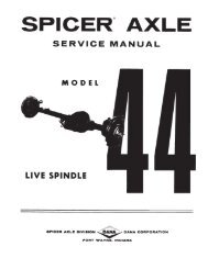
<strong>Spicer</strong> ®<br />
<strong>Drive</strong> <strong>Axles</strong><br />
<strong>Service</strong> <strong>Manual</strong><br />
<strong>Spicer</strong><br />
AXSM-8942<br />
September 2007<br />
® <strong>Drive</strong> <strong>Axles</strong>
TABLE ABLE OF OF CONTENTS<br />
CONTENTS<br />
CONTENTS<br />
○ ○ ○ ○ ○ ○ ○ ○ ○ ○ ○ ○ ○ ○ ○ ○ ○ ○ ○ ○ ○ ○<br />
○ ○ ○ ○ ○ ○ ○ ○ ○ ○ ○<br />
○ ○ ○ ○ ○ ○ ○ ○ ○ ○ ○ ○ ○ ○ ○ ○ ○ ○ ○<br />
○ ○ ○ ○ ○ ○ ○ ○ ○ ○ ○ ○ ○ ○<br />
○ ○ ○ ○ ○ ○ ○ ○ ○ ○ ○ ○ ○ ○ ○ ○ ○ ○ ○ ○ ○<br />
○ ○ ○ ○ ○ ○ ○ ○ ○ ○ ○ ○ ○ ○ ○ ○ ○<br />
○ ○ ○ ○ ○ ○ ○ ○ ○ ○ ○ ○ ○ ○ ○ ○<br />
○ ○ ○ ○ ○ ○<br />
○ ○ ○ ○ ○ ○ ○ ○ ○ ○ ○ ○ ○<br />
○ ○ ○ ○ ○ ○ ○ ○ ○ ○ ○ ○ ○ ○<br />
○ ○ ○ ○ ○ ○ ○ ○ ○ ○ ○ ○ ○ ○ ○ ○ ○<br />
○ ○ ○ ○ ○ ○ ○ ○ ○ ○ ○ ○ ○ ○ ○ ○ ○ ○ ○<br />
○ ○ ○ ○ ○ ○ ○ ○ ○ ○ ○ ○ ○ ○ ○ ○ ○ ○ ○<br />
○ ○ ○ ○ ○ ○ ○ ○ ○ ○ ○ ○ ○ ○ ○ ○ ○ ○ ○<br />
○ ○ ○ ○ ○ ○ ○ ○ ○ ○ ○ ○ ○ ○ ○ ○<br />
○ ○ ○ ○ ○ ○ ○ ○ ○ ○ ○ ○ ○ ○ ○<br />
○ ○ ○ ○<br />
○ ○ ○ ○ ○ ○ ○ ○ ○ ○ ○<br />
○ ○ ○ ○ ○ ○ ○ ○ ○ ○<br />
○ ○ ○ ○ ○ ○ ○ ○ ○ ○ ○ ○ ○<br />
○ ○ ○ ○ ○ ○<br />
○ ○ ○ ○ ○ ○ ○ ○ ○ ○ ○ ○ ○ ○ ○<br />
○ ○ ○ ○ ○ ○ ○ ○ ○ ○ ○<br />
○ ○ ○ ○ ○ ○ ○ ○ ○<br />
○ ○ ○ ○ ○ ○ ○ ○ ○ ○ ○ ○ ○ ○ ○ ○ ○ ○ ○ ○ ○ ○<br />
○ ○ ○ ○ ○ ○ ○ ○ ○ ○ ○ ○<br />
○ ○ ○ ○ ○ ○ ○ ○ ○ ○ ○ ○ ○ ○ ○ ○ ○<br />
Axle Identification 2<br />
Model Identification Numbering System 3<br />
Gear Set Identification 3<br />
Axle Lubricant Recommendations 4<br />
General Precautions 5<br />
Standard Axle Components 6<br />
Pinion-Up Axle Components 7<br />
Removal of Differential Carrier from Axle Housing 8<br />
Removal of Differential from Carrier 9<br />
Differential Disassembly 10<br />
Pinion Disassembly 12<br />
Cleaning and Inspection 13<br />
Pinion Assembly 14<br />
Pinion Position 17<br />
Differential Assembly 19<br />
Differential Installation 20<br />
Ring Gear and Pinion Tooth Contact Pattern 21<br />
Installation of Carrier into Axle Housing 22<br />
Fastener Torques and Axle Specifications 23<br />
<strong>Drive</strong>r Controlled Differential Lock 24<br />
<strong>Drive</strong>r Controlled Differential Lock Components 25<br />
Towing Procedures/Instructions 26<br />
Carrier Removal 27<br />
Removal of Diff-Lock Assembly 28<br />
Installation of Diff-Lock Assembly 29<br />
Carrier Installation 30<br />
Checking Differential Lock Operation 31<br />
Recommended <strong>Service</strong> Tools 32<br />
GENUINE GENUINE SPICER SPICER SER SERVICE SER SERVICE<br />
VICE P PPAR<br />
P PAR<br />
AR ARTS AR TS<br />
Should an axle assembly require replacement component<br />
parts, it is recommended that <strong>Spicer</strong> Heavy Axle<br />
<strong>Service</strong> Parts be used. <strong>Spicer</strong> Heavy Axle <strong>Service</strong> Parts<br />
are manufactured under the same rigid specification as<br />
are original equipment axle components. This assures<br />
the customer who uses genuine <strong>Spicer</strong> service parts,<br />
maximum reliability for a <strong>Spicer</strong> Heavy Axle assembly.<br />
They may be obtained through your vehicle manufacturer.<br />
The use of non-original <strong>Spicer</strong> service parts may<br />
cause premature component failure and may void the<br />
warranty.<br />
1<br />
The items included in this book are currently being<br />
offered as service parts at the time of printing. The<br />
part numbers and illustrations are provided specifically<br />
for reference purposes only. Therefore, <strong>Spicer</strong> reserves<br />
the right to update this manual without notice or<br />
liability.
All axle assemblies are identified with two tags. One<br />
located on the differential carrier, and the other located<br />
on the right hand side of the axle housing.<br />
The differ differential differ ential carrier carrier t ttag<br />
t ag contains the following:<br />
Dana part number, julian date code, and ratio. Optional<br />
items include customer part number, line set number, and<br />
the last six digits of the vehicle serial number.<br />
DANA ANA P PPAR<br />
P PAR<br />
AR ART AR<br />
NUMBER<br />
NUMBER<br />
CUS CUS CUSTOMER<br />
CUS OMER<br />
PAR AR ART AR T NUMBER<br />
NUMBER<br />
(OPTIONAL)<br />
(OPTIONAL)<br />
Axle Assembly Tag<br />
LAS LAS LAST LAS LAS T SIX SIX DIGITS DIGITS OF OF<br />
OF<br />
VEHICLE VEHICLE SERIAL SERIAL NUMBER<br />
NUMBER<br />
(OPTIONAL)<br />
(OPTIONAL)<br />
Pinion Below<br />
Center<br />
MODEL<br />
MODEL<br />
JULIAN JULIAN D DDATE<br />
D TE<br />
CODE<br />
CODE<br />
LINE LINE SET<br />
SET<br />
NUMBER<br />
NUMBER<br />
(OPTIONAL)<br />
(OPTIONAL)<br />
2<br />
MODEL MODEL MODEL YEAR<br />
YEAR<br />
DANA ANA P PPAR<br />
P AR ART AR<br />
NUMBER<br />
NUMBER<br />
AXLE AXLE IDENTIFICA<br />
IDENTIFICA<br />
IDENTIFICATION<br />
IDENTIFICA TION<br />
JULIAN JULIAN D DDATE<br />
D TE CODE CODE<br />
CODE<br />
96 96 0 0070<br />
0<br />
CUS CUS CUSTOMER<br />
CUS CUS OMER OMER<br />
PAR AR ART ART<br />
T NUMBER<br />
NUMBER<br />
(OPTIONAL)<br />
(OPTIONAL)<br />
(OPTIONAL)<br />
Carrier Tag<br />
LAS LAST LAS T SIX SIX DIGITS DIGITS OF OF<br />
OF<br />
VEHICLE VEHICLE SERIAL SERIAL NUMBER<br />
NUMBER<br />
(OPTIONAL)<br />
(OPTIONAL)<br />
Pinion Above<br />
Center<br />
DAY Y OF OF YEAR YEAR<br />
YEAR<br />
LINE LINE SET SET<br />
SET<br />
NUMBER<br />
NUMBER<br />
(OPTIONAL)<br />
(OPTIONAL)<br />
JULIAN JULIAN D DDATE<br />
D TE<br />
CODE<br />
CODE<br />
The axle axle a aassembl<br />
a assembl<br />
ssembl ssembly ssembl y tt<br />
tag t ag contains the following items:<br />
Dana part number, julian date code, axle model, and ratio.<br />
Optional items include customer part number, line set<br />
number, and the last six digits of the vehicle serial number.
MODEL MODEL MODEL IDENTIFICA<br />
IDENTIFICA<br />
IDENTIFICATION IDENTIFICA TION NUMBERING NUMBERING NUMBERING SYSTEM<br />
SYSTEM<br />
Family<br />
(S = <strong>Spicer</strong>)<br />
Nominal Load<br />
Carrying Capacity<br />
(230 = 23,000 Lbs.)<br />
(260 = 26,000 Lbs.)<br />
GEAR GEAR SET SET IDENTIFICA<br />
IDENTIFICA<br />
IDENTIFICATION<br />
IDENTIFICA<br />
IDENTIFICA TION<br />
Man Manufactur Man ufactur ufacturer's ufacturer's<br />
er's Da Date- Da e- Date gear set was made.<br />
<strong>Spicer</strong> <strong>Spicer</strong> <strong>Spicer</strong> T TTrademark<br />
T ademark ademark- ademark - Company logo and location of<br />
manufacturing facility.<br />
300GP2 00GP2 00GP203- 00GP2 3- Part number of pinion gear. (TYPICAL)<br />
Too oo ooth oo th Combina Combination(i.e. Combina tion(i.e. 4 441-1<br />
4 1-1 1-11)- 1-1 1)- Indicates the pinion<br />
has 11 teeth and the ring gear has 41 teeth which<br />
results in a 3:73:1 ratio.<br />
Ma Ma Matched Ma tched Se Se Set Se t Number Number Number- Number - <strong>Spicer</strong> ring gears and pinions<br />
are manufactured as matched sets. Both ring gear and<br />
pinion are marked with a corresponding number (i.e.<br />
260), which identifies them as a matched set.<br />
A gear set that does not have the same match set<br />
numbers should not be run together. If either ring gear<br />
or pinion require replacement, a new matched set must<br />
be used.<br />
Backla Backlash Backla sh Etch- Etch- Indicates backlash setting for assembly.<br />
Pinion Pinion Etch-<br />
Etch- Indicator for proper pinion position shim<br />
stack up. See See Pinion Pinion P PPosition<br />
P osition Section. Section.<br />
Section.<br />
S 230 S L<br />
Gearing Type<br />
(S = Single Reduction)<br />
3<br />
41-11<br />
TOOTH<br />
COMBINATION<br />
SPICER<br />
TRADEMARK<br />
PART<br />
NUMBER<br />
Options<br />
(N = *No-SPIN ® Differential)<br />
(L = <strong>Drive</strong>r Controlled Diff. Lock)<br />
(B = Bus)<br />
HEAT<br />
CODE<br />
* No-SPIN ® is a registered trademark of Tractech<br />
SPICER<br />
TRADEMARK<br />
PINION ETCH<br />
MFG.<br />
DATE<br />
L10<br />
+15<br />
260<br />
BACKLASH ETCH<br />
MATCHED<br />
SET NUMBER<br />
260
To ensure proper lubrication and operating temperature,<br />
correct lubricants and lubricant levels must be obtained.<br />
RECOMMENDED GEAR LUBRICANTS<br />
Mineral or Synthetic based hypoid gear lubricants that<br />
meet or exceed military specification MIL-L-2105D, and<br />
API service classification GL-5, are the minimum requirements<br />
for use in <strong>Spicer</strong> Medium and Heavy Duty <strong>Drive</strong><br />
<strong>Axles</strong>.<br />
The table below indicates which SAE viscosities are<br />
recommended for various temperature ranges the vehicle<br />
will encounter.<br />
Cº<br />
Fº<br />
-40<br />
-40<br />
SAE 140<br />
SAE 85W-140<br />
SAE 90<br />
SAE 80W-140<br />
SAE 80W<br />
SAE 75W-140<br />
SAE 75W-90<br />
SAE 75W<br />
-26<br />
-12<br />
-15 +10<br />
0<br />
+32 +40<br />
SERVICE<br />
Recommended lubricant change intervals are dependent<br />
on the application and operating environment. The<br />
following chart should be used to establish proper<br />
change intervals.<br />
+4<br />
+15<br />
+60<br />
+27<br />
+80<br />
AMBIENT AIR TEMPERATURE<br />
SUBMERSION OR DEEP WATER FORDING<br />
+38 Cº<br />
+100<br />
In the event the carrier housing should become<br />
submerged in water, particularly if over the vent or<br />
breather, it is recommended that the lubricant be<br />
drained and all internal parts be inspected for water<br />
damage and/or contamination. Reassemble the carrier to<br />
the housing and refill with specified gear lubricant.<br />
Fº<br />
AXLE XLE LUBRICANT RECOMENDATIONS<br />
4<br />
PETR<br />
PETROLEUM PETR OLEUM OLEUM B<br />
BASED B<br />
B<br />
ASED S<br />
SYNTHETIC S<br />
YNTHETIC B<br />
BASED**<br />
B<br />
ASED**<br />
APPLICA<br />
APPLICA<br />
APPLICATION<br />
APPLICA<br />
APPLICA<br />
TION<br />
TION<br />
MILES MILES INTER<br />
INTERVAL INTER<br />
AL MILES MILES MILES INTER<br />
INTERVAL<br />
INTER<br />
INTER<br />
AL<br />
On Highway 100,000 1 Year 250,000 3 Year<br />
* * Severe <strong>Service</strong><br />
and 50,000 1 Year 100,000 1 Year<br />
On-Off Highway<br />
* Severe service includes any applications operating at<br />
or near maximum GVW or GCW ratings. This<br />
includes normally wet or dusty environment, or<br />
consistent high load and low speed applications.<br />
** Includes Semi-Synthetic blends that meet<br />
MIL-L-2105D specifications.<br />
AFTER OVERHAUL OR CHANGE INTERVALS<br />
Fill the axle assembly to the bottom of housing fill hole as<br />
shown in the illustration below. It is recommended that<br />
following an overhaul, each side of the axle be jacked up<br />
seperately to approximately six inches and held into<br />
position for one minute. This procedure will allow<br />
adequate lubricant to flow into the wheel ends and help<br />
eliminate the possibility of premature damage to wheel<br />
bearings and seals. Lower the vehicle to the floor and<br />
allow ten minutes for lube to return to normal level. Check<br />
and refill assembly to bottom of fill hole to replace the<br />
lubricant that was directed into the wheel ends.<br />
NO NOTE: NO TE: Lubricant close enough to the bottom of the fill hole to be seen or<br />
touched is not sufficient. Lubricant must be level with the fill hole.
GENERAL GENERAL PRECAUTIONS<br />
PRECAUTIONS<br />
GENERAL AXLE DESCRIPTION<br />
This manual covers maintenance and rebuild procedures<br />
for the <strong>Spicer</strong> S230-S, S230-SL, and S260-SB rear drive<br />
axle assemblies.<br />
The <strong>Spicer</strong> Heavy Duty Single Reduction rear drive axle<br />
is a full floating axle assembly, with a hypoid gear carrier<br />
assembly, using a High Strength Low Alloy (HSLA) steel<br />
axle housing. The hypoid pinion is straddle mounted<br />
with two tapered roller bearings behind the pinion teeth<br />
for thrust and radial loads. A pilot bearing is located on<br />
the nose of the pinion for radial load. The differential<br />
itself uses four precision forged pinion mate gears, a<br />
forged cross, and precision forged side gears.<br />
SAFTEY PRECAUTIONS<br />
Safety Safety Safety glasses glasses should should be be wor worn wor<br />
at at all all all times times when when assembling<br />
assembling<br />
or or disassembling disassembling axles.<br />
axles.<br />
Proper service and repair of vehicle components is<br />
important to the safe and reliable operation of all motor<br />
vehicles. This applies particularly to driving axles such as<br />
the ones described in this manual. The procedures<br />
recommended and described in this manual are tested,<br />
effective methods for performing service operations.<br />
Follow each procedure closely, making use of both the<br />
text and illustrations. Some of these service procedures<br />
show the use of certain tools designed specifically for<br />
the operation being performed. They are shown as a<br />
preferred means of performing the operation. It is not<br />
practical to anticipate and advise the service trade of all<br />
possible alternative methods, and of all possible hazardous<br />
consequences that could occur.<br />
IMPOR IMPORTANT<br />
IMPOR ANT<br />
READ READ READ THIS THIS SECTION SECTION BEFORE BEFORE ST STAR ST AR ARTING AR TING<br />
ANY ANY SER SERVICE SER VICE PROCEDURES<br />
PROCEDURES<br />
5<br />
Accordingly, anyone who uses a service procedure or tool<br />
different than shown must insure that their safety, and<br />
the vehicle's safety, will not be jeopardized by the service<br />
method selected.<br />
END YOKES AND FLANGES<br />
CA CAUTION: CA UTION: Hammering Hammering on on end end y yyok<br />
y ok okes ok s can can close<br />
close<br />
in in the the bearing bearing bor bores bor s s or or misalign misalign misalign y yyok<br />
y ok oke ok e lugs lugs and and r rresult<br />
r sult<br />
in in in earl early earl y failur failur failures failur failur s of of journal journal needle needle bearings bearings bearings or or o oother<br />
o other<br />
ther<br />
driv driveline driv eline component components. component s. Serious Serious damage damage can can also also be<br />
be<br />
done done int internall int internall<br />
ernall ernally ernall y t tto<br />
t o the the ring ring and and pinion pinion pinion se se set se t or or pinion<br />
pinion<br />
bearings bearings bb<br />
by bb<br />
y hammering hammering on on e eext<br />
e xt xternal xt ernal par par parts. par s. End End y yyok<br />
y ok okes ok<br />
or or companion companion companion flange flanges flange flanges<br />
s should should be be be r rremo<br />
r emo emoved emo ed or or inst installed inst alled<br />
using using the the r rrecommended<br />
r ecommended me methods me thods outlined outlined outlined in in this<br />
this<br />
man manual. man manual.<br />
ual.<br />
CLEANLINESS<br />
Axle components should be steam cleaned prior to<br />
removal from the vehicle. Dirt is abrasive and will cause<br />
premature wear of otherwise serviceable parts.<br />
<strong>Service</strong> personnel should use a wash tank for thorough<br />
cleaning of parts just prior to reassembly.<br />
CAUTION<br />
BR BRAKE BR AKE LININGS LININGS CONT CONTAIN CONT AIN NON-ASBES<br />
NON-ASBES<br />
NON-ASBESTOS NON-ASBES<br />
NON-ASBES OS FIBER FIBERS FIBER FIBER<br />
BREA BREATHING BREA THING BR BRAKE BR AKE DUS DUST DUS DUST<br />
T MA MAY MA Y BE BE BE HAZARDOUS HAZARDOUS TT<br />
TO TT<br />
O Y YYOUR<br />
YY<br />
OUR HEAL HEALTH HEAL TH AND<br />
AND<br />
MA MAY MA Y CA CAUSE CA CA USE SERIOUS SERIOUS SERIOUS RESPIR RESPIRATOR<br />
RESPIR OR ORY ORY<br />
Y OR OR O OOTHER<br />
O THER BODIL BODILY BODIL Y HARM.<br />
HARM.<br />
AVOID OID CREA CREATING CREA TING DUS DUST DUS<br />
DO DO DO NO NOT NO REMO REMO REMOVE REMO VE BR BRAKE BR AKE DR DRUM DR DR UM WITHOUT WITHOUT WITHOUT PR PROPER PR PROPER<br />
OPER PR PROTECTIVE PR TECTIVE EQ EQUIPMENT<br />
EQ UIPMENT UIPMENT. UIPMENT<br />
DO DO DO NO NOT NO W WWORK<br />
W ORK ON ON ON LININGS LININGS WITHOUT WITHOUT PR PROPER PR OPER PR PROTECTIVE PR TECTIVE TECTIVE EQ EQUIPMENT<br />
EQ UIPMENT UIPMENT. UIPMENT<br />
DO DO DO NO NOT NO REPLA REPLACE REPLA CE LININGS LININGS WITHOUT WITHOUT WITHOUT PR PR PROPER PR PR OPER PR PROTECTIVE PR TECTIVE EQ EQUIPMENT<br />
EQ UIPMENT UIPMENT. UIPMENT<br />
DO DO NO NOT NO A AATTEMPT<br />
A TTEMPT T TTO<br />
T O S SSAND,<br />
S AND, GRIND, GRIND, CHISEL, CHISEL, FILE, FILE, HAMMER HAMMER OR OR AL ALTER AL AL TER BR BRAKE BR AKE<br />
LININGS LININGS IN IN ANY ANY MANNER MANNER WITHOUT WITHOUT PR PROPER PR PROPER<br />
OPER PR PROTECTIVE PR TECTIVE EQ EQUIPMENT<br />
EQ EQUIPMENT<br />
UIPMENT UIPMENT. UIPMENT<br />
FOLL OLL OLLOW OLL W 0.S.H.A. 0.S.H.A. S SSTAND<br />
S AND ANDARDS ANDARDS<br />
ARDS F FFOR<br />
F OR PR PROPER PR PR OPER PR PROTECTIVE PR TECTIVE DEVICES DEVICES DEVICES TT<br />
TO T O BE BE USED<br />
USED<br />
WHEN WHEN WHEN W WWORKING<br />
W WORKING<br />
ORKING WITH WITH BR BR BRAKE BR AKE MA MATERIALS.<br />
MA TERIALS.
Adjusting Ring Lock<br />
Temperature<br />
Sensor Plug<br />
(35 - 45 Lb-Ft)<br />
(47 - 61 N-m)<br />
Adjusting Ring Lock Bolt<br />
(20 - 30 Lb-Ft)<br />
(27 - 41 N-m)<br />
Axle Shaft<br />
Fill Plug<br />
(35-45 Lb-Ft)<br />
(47 - 61 N-m)<br />
Differential Case Half<br />
Differential Bearing Cap<br />
Carrier Housing<br />
Breather<br />
Pilot Bearing<br />
Housing<br />
Drain Plug (35 - 45 Lb-Ft)<br />
(47 - 61 N-m)<br />
Differential Case Bolt<br />
(160 - 180 Lb-Ft)<br />
(217- 244 N-m)<br />
6<br />
ST STANDARD ST ANDARD AXLE AXLE COMPONENTS<br />
COMPONENTS<br />
Differential Bearing Cap Bolt<br />
(295 - 340 Lb-Ft)<br />
(400 - 461 N-m)<br />
Washer<br />
Differential Bearing<br />
Adjusting Ring<br />
Differential Bearing Cup<br />
Differential Bearing Cone<br />
Differential Case Flange Half<br />
Ring Gear<br />
Ring Gear Rivet (45-50 tons)<br />
(41-45 metric tonnes)<br />
Thrust Washer<br />
Ring Gear Bolt Kit - <strong>Service</strong><br />
Differential Pinion Mate<br />
Differential Cross Shaft<br />
Differential Side Gear<br />
Thrust Washer<br />
No-Spin® Differential<br />
Carrier Mounting Bolt<br />
(240 - 260 Lb-Ft)<br />
(325 - 353 N-m)<br />
Inner Pinion Bearing Cone<br />
Inner Pinion Bearing Cup<br />
Pinion Preload Spacer (Selective)<br />
Pinion Position Shim<br />
Pinion Bearing Cage<br />
Outer Pinion Bearing Cup<br />
Bearing Cage Bolt<br />
(160-180 Lb-Ft)<br />
Pinion<br />
(217- 244 N-m)<br />
Outer Pinion Bearing Cone<br />
Pinion Seal<br />
End Yoke Assembly<br />
Pinion Hex Nut<br />
(900 - 1,200 Lb-Ft)<br />
(1,220 - 1,627 N-m)<br />
Washer
PINION-UP PINION-UP AXLE AXLE COMPONENTS<br />
COMPONENTS<br />
Axle Shaft<br />
Fill Plug<br />
(35-45 Lb-Ft)<br />
(47 - 61 N-m)<br />
Temperature<br />
Sensor Plug<br />
(35 - 45 Lb-Ft)<br />
(47 - 61 N-m)<br />
Adjusting Ring Lock<br />
Differential Bearing Cap<br />
Adjusting Ring Lock Bolt<br />
(20 - 30 Lb-Ft)<br />
(27 - 41 N-m)<br />
Carrier Housing<br />
Breather<br />
Carrier Mounting Bolt<br />
(240 - 260 Lb-Ft)<br />
(325 - 353 N-m)<br />
Housing<br />
Differential Cross Shaft<br />
7<br />
Drain Plug (35 - 45 Lb-Ft)<br />
(47 - 61 N-m)<br />
Differential Bearing Cap Bolt<br />
(295 - 340 Lb-Ft)<br />
(400 - 461 N-m)<br />
Washer<br />
Differential Bearing<br />
Adjusting Ring<br />
Differential Bearing Cup<br />
Thrust Washer<br />
Differential Bearing Cone<br />
Differential Case Bolt<br />
(160 - 180 Lb-Ft)<br />
(217- 244 N-m)<br />
Differential Case Half<br />
Differential Pinion Mate<br />
Thrust Washer<br />
Ring Gear Rivet (45-50 tons)<br />
Ring Gear<br />
(41-45 metric tonnes)<br />
Differential Case Flange Half<br />
Pilot Bearing<br />
Pinion<br />
Differential Side Gear<br />
Carrier Mounting Bolt<br />
(240 - 260 Lb-Ft)<br />
(325 - 353 N-m)<br />
Inner Pinion Bearing Cone<br />
Pinion Preload Spacer (Selective)<br />
Inner Pinion Bearing Cup<br />
Pinion Position Shim<br />
Pinion Bearing Cage<br />
Bearing Cage Bolt<br />
(160-180 Lb-Ft)<br />
(217- 244 N-m)<br />
Outer Pinion Bearing Cup<br />
Outer Pinion Bearing Cone<br />
Pinion Seal<br />
End Yoke Assembly<br />
Washer<br />
Pinion Hex Nut<br />
(900 - 1,200 Lb-Ft)<br />
(1,220 - 1,627 N-m)
IMPOR IMPORTANT<br />
IMPOR ANT ANT: ANT : If If the the the v vvehicle<br />
v ehicle is is equipped equipped with with driv driver driv driv er<br />
contr controlled contr olled differ differential differ ential lock, lock, see see instructions instructions begining<br />
begining<br />
on on page page 2 224.<br />
2 4. TT<br />
To TT<br />
o t ttow<br />
t w a a v vvehicle<br />
vv<br />
ehicle with with driv driver driv er contr controlled contr olled<br />
differ differential differ ential lock, lock, see see instructions instructions on on page page 2 226.<br />
2 6.<br />
NO NO NOTE: NO NO TE: St Steam St eam clean clean axle axle a aassembl<br />
a assembl<br />
ssembl ssembly. ssembl<br />
1. 1. Block wheels.<br />
2. 2. Remove axle housing drain plug and drain lubricant.<br />
3. 3. Disconnect drive shafts at the rear U-joint.<br />
NO NOTE: NO TE: If If end end y yyok<br />
y ok oke ok e and/or and/or seal seal is is t tto<br />
t o be be r rreplaced,<br />
rr<br />
eplaced,<br />
loosen loosen loosen y yyok<br />
y ok oke ok e n nnut<br />
n ut a aat<br />
a t this this time.<br />
time.<br />
4. 4. Remove axle shaft flange nuts.<br />
5. 5. Hold a large brass drift or a brass hammer against<br />
the center of the axle shaft flange. Strike the drift<br />
with sharp blows from a large hammer or sledge<br />
until the axle shaft separates from the hub.<br />
CA CAUTION: CA UTION: Do Do no no not no no t strik strik strike strik e the the flange flange dir directl dir ectl ectly ectl<br />
with with with a a st st steel st eel hammer hammer or or sledge. sledge. This This This ma may ma may<br />
y cr crack cr ack and<br />
and<br />
splint splinter splint er ma material, ma erial, possibl possibly possibl y causing causing serious serious or or fa fatal fa al<br />
injury injury. injury injury.<br />
. Do Do no not no not<br />
t pry pry or or chisel chisel axle axle flange flange a aaway<br />
aa<br />
y fr from fr om h hhub<br />
h ub<br />
or or damage damage damage t tto<br />
t o sealing sealing sur surface sur face faces face s could could occur occur. occur<br />
6. 6. Remove axle shafts.<br />
7. Support the differential carrier assembly on a roller<br />
jack. Secure as necessary to prevent it from<br />
falling off the jack when removed from the housing.<br />
8<br />
REMOV REMOVAL REMOV AL OF OF DIFFERENTIAL<br />
DIFFERENTIAL<br />
CARRIER CARRIER FROM FROM FROM AXLE AXLE HOUSING<br />
HOUSING<br />
8. 8. Use a breaker bar to loosen the differential carrierto-housing<br />
mounting bolts. Remove all bolts except<br />
top two. These two bolts will prevent the carrier<br />
assembly from falling.<br />
9. 9. Separate differential carrier from the housing using<br />
removal slots. See See See F FFigur<br />
F igur igure igur e 1. 1. Be certain carrier is<br />
balanced properly on jack, and remove top two<br />
carrier-to-housing mounting bolts. Remove<br />
differential carrier assembly from the axle housing.<br />
Remo emo emoval emo al slot slot<br />
Remo emo emo emoval emo al slot<br />
slot<br />
Figur igur igure igur e 1<br />
1<br />
10. 0. Mount carrier assembly in a suitable rebuild stand.<br />
(Refer to Recommended ecommended <strong>Service</strong> <strong>Service</strong> T TTools<br />
T ools ools, ools pg. 32).<br />
Differ Differ Differential Differ Differ ential Carrier Carrier R RRemo<br />
R emo emoval emo al al Complet Complet Complete<br />
Complet Complet
REMOV REMOVAL REMOV REMOVAL<br />
AL OF OF DIFFERENTIAL DIFFERENTIAL FROM FROM CARRIER<br />
CARRIER<br />
1. 1. Remove adjusting ring locks from bearing caps.<br />
2. 2. Match mark one differential bearing cap and leg with<br />
center punch or chisel for correct reassembly. See<br />
See<br />
Figur igur igure igur e 2.<br />
2.<br />
Figur igur igure igure<br />
e 2<br />
2<br />
9<br />
3. 3. Loosen four bearing cap retainer bolts.<br />
4. 4. Loosen adjusting rings, relieving bearing preload.<br />
5. Remove four bearing cap retainer bolts.<br />
6. 6. Remove bearing caps.<br />
7. Remove adjusting rings.<br />
8. 8. 8. Carefully lift the ring gear and differential<br />
subassembly out of the carrier.<br />
NO NOTE: NO TE: Use Use car care car e no not no not<br />
t tt<br />
to tt<br />
o damage damage the the ring ring gear gear and<br />
and<br />
pinion. pinion. If If either either ring ring gear gear or or pinion pinion sho show sho show<br />
w signs signs of<br />
of<br />
damage, damage, the they the y m mmust<br />
m ust be be rr<br />
replaced rr<br />
eplaced a aas<br />
a as<br />
s a a ma ma matched ma tched se set. se t.<br />
R RRemo<br />
R emo emoval emo al of of Differ Differential Differ Differential<br />
ential Complet Complete Complet
Differential Bearing Cone<br />
Differential Bearing Cup<br />
Differential Bearing<br />
Adjusting Ring<br />
Differential Case Half<br />
Differential Case Bolt<br />
(160-180 Lb-Ft)<br />
(217- 244 N-m)<br />
1. 1. Match mark differential case halfs with punch or<br />
chisel for correct alignment in reassembly.<br />
See See FF<br />
Figur F igur igure igur e 3. 3.<br />
3.<br />
Figur igur igur igure igur e 3<br />
3<br />
Thrust Washer<br />
Differential Side Gear<br />
Thrust Washer<br />
10<br />
DIFFERENTIAL DIFFERENTIAL DIFFERENTIAL DISASSEMBL<br />
DISASSEMBLY<br />
DISASSEMBL<br />
DISASSEMBL<br />
Differential Bearing Cone<br />
Ring Gear Rivet (45-50 tons)<br />
Differential Pinion Mate<br />
Differential Cross Shaft<br />
Ring Gear<br />
Differential Case Half<br />
Differential Bearing Cup<br />
2. 2. Remove differential case bolts and lift off differential<br />
case half.<br />
3. 3. Remove thrust washer and differential side gear.<br />
4. 4. Lift out cross shaft, pinion mates, and thrust<br />
washers.<br />
Differential Bearing<br />
Adjusting Ring<br />
5. 5. Remove second differential side gear and thrust<br />
washer.<br />
6. 6. If differential side bearings are to be replaced,<br />
remove old bearings using a suitable puller.<br />
See See F FFigur<br />
F igur igure igur e 4.<br />
4.
DIFFERENTIAL DIFFERENTIAL DIFFERENTIAL DISASSEMBL<br />
DISASSEMBLY<br />
DISASSEMBL<br />
Figur igur igure igure<br />
e 4 4<br />
4<br />
NO NO NOTE: NO TE: Inspect Inspect all all par parts, par s, including including including the the machined<br />
machined<br />
sur surface sur sur face faces faces<br />
s of of the the ca case ca se half half. half<br />
If If an an any an y gear gears gear s ar are ar ar e tt<br />
to tt<br />
o be be be r rreplaced,<br />
r eplaced, the they the y m mmust<br />
m must<br />
ust be<br />
be<br />
replaced eplaced in in ma matched ma tched se sets. se s. Inspect Inspect thrust thrust w wwasher<br />
w sher shers sher<br />
for for scoring scoring and and e eexce<br />
e ce cessiv ce ssiv ssive ssiv e w wwear<br />
w ear ear. ear . R RReplace<br />
R eplace all all w wworn<br />
w orn<br />
or or damaged damaged par parts. par s.<br />
NO NOTE: NO TE: Ring Ring gear gear gear bolt bolt kit kits kit s ar are ar ar e a aavailable<br />
aa<br />
ailable a aas<br />
a as<br />
s a a r rreplace<br />
rr<br />
eplace<br />
ment ment ment for for ring ring ring gear gear riv rivets, riv s, see see P PPar<br />
P ar arts ar s List List man manual man ual for<br />
for<br />
par part par par t n nnumber<br />
n umber informa information.<br />
informa information.<br />
tion.<br />
7. When it is necessary to remove ring gear from the<br />
differential case, carefully center punch each rivet<br />
head. Use a 9/16 inch drill bit. Drill through rivet<br />
heads to depth shown. Next, use a rounded type<br />
punch to drive out remaining portion of the rivet.<br />
11<br />
CORRECT PROCEDURE<br />
Ca Case Ca se Ring Ring Gear<br />
Gear<br />
CA CAUTION: CA UTION: Alw Always Alw s use use a a soft soft hammer hammer hammer or or H.D.<br />
H.D.<br />
pla plastic pla stic head head hammer hammer t tto<br />
t o strik strike strik e punch.<br />
punch.<br />
INCORRECT PROCEDURE<br />
Ring Ring Gear Gear<br />
Ca Case Ca se<br />
NO NOTE: NO TE: Do Do Do no not no t use use use a a chisel chisel t tto<br />
t o r rremo<br />
r emo emove emo e riv riv rivet riv t heads,<br />
heads,<br />
damage damage t tto<br />
t o differ differential differ ential ca case ca se ma may ma y rr<br />
result. r sult.<br />
Differ Differential Differ ential Disa Disassembly Disa ssembly Complet Complete Complet
Carrier Housing<br />
Pilot Bearing<br />
Pinion<br />
Inner Pinion Bearing Cone<br />
Inner Pinion Bearing Cup<br />
Pinion Preload Spacer (Selective)<br />
1. 1. Remove pinion bearing cage mounting bolts.<br />
2. 2. Remove pinion assembly from carrier housing.<br />
If difficulty is encountered in removing pinion<br />
assembly from carrier housing, place a brass drift on<br />
inner end of pinion and tap lightly with hammer.<br />
NO NOTE: NO TE: R RRetain<br />
R ain ain shims shims for for possible possible use use during<br />
during<br />
rea ea eassembl ea ssembl ssembly. ssembl<br />
3. 3. 3. Hold yoke stationary. Remove nut and washer. A<br />
torque multiplier may be required to loosen nut.<br />
4. 4. Remove the end yoke using a suitable puller. See<br />
Recommended ecommended <strong>Service</strong> <strong>Service</strong> T TTools<br />
T ools ools, ools pg. 32.<br />
5. 5. Remove pinion from cage assembly.<br />
Pinion Position Shim(s)<br />
NO NOTE: NO NO TE: It It ma may ma y be be nece necessary nece ssary t tto<br />
t o tt<br />
tap t ap out outer out er end end of<br />
of<br />
pinion pinion pinion with with a a soft soft hammer hammer, hammer , t ttaking<br />
t aking car care car e no not no t t tto<br />
t o damage<br />
damage<br />
thr threads. thr thr eads.<br />
12<br />
Pinion Bearing Cage<br />
Outer Pinion Bearing Cup<br />
Bearing Cage Bolt<br />
(160-180 Lb-Ft)<br />
(217-244 N-m)<br />
PINION PINION DISASSEMBL<br />
DISASSEMBLY<br />
DISASSEMBL<br />
Outer Pinion Bearing Cone<br />
Pinion Seal<br />
End Yoke Assembly<br />
Washer<br />
6. 6. Located between the pinion bearings is a selective<br />
bearing preload spacer. Retain this selective preload<br />
spacer for possible use during reassembly.<br />
7. Remove the old pinion seal and discard. Always use<br />
a new seal at the time of reassembly.<br />
8. 8. 8. Lift out the outer pinion bearing cone.<br />
Pinion Hex Nut<br />
(900 - 1,200 Lb-Ft)<br />
(1,220 - 1,627 N-m)<br />
9. 9. 9. Remove inner pinion bearing cup, using a suitable<br />
adapter and press or puller.<br />
CA CAUTION: CA UTION: Do Do Do no no not no not<br />
t nick nick bearing bearing bearing bor bore. bor e.<br />
10. 0. Remove the outer pinion bearing cup, use the same<br />
procedure as in step 9.<br />
11. 1. Remove pilot bearing from end of pinion.<br />
12. 2. Remove inner bearing cone from pinion.<br />
Pinion Pinion Pinion Disa Disassembly Disa Disassembly<br />
ssembly Complet Complete<br />
Complet
CLEANING CLEANING AND AND INSPECTION<br />
INSPECTION<br />
CLEANING<br />
1. 1. Parts should be cleaned with emulsion cleaners or<br />
petroleum base cleaning solvent.<br />
NO NO NOTE: NO TE: Alk Alkaline Alk aline t ttype<br />
t ype solutions solutions ma may ma y cause cause damage damage t tto<br />
t<br />
machined machined machined sur surface sur surface<br />
face faces face s and and should should should be be a aavoided.<br />
a oided.<br />
2. 2. Make sure interior of axle housing is clean prior to<br />
reassembly.<br />
3. 3. Clean all gasket surfaces of old material.<br />
DRYING<br />
Use soft, clean, lintless towels or rags to dry components<br />
after cleaning. Bearings should NOT be dried by<br />
spinning with compressed air. This can damage mating<br />
surfaces due to the lack of lubrication.<br />
After drying, parts should be coated with a light coat<br />
of lubricant or rust inhibitor to prevent damage from<br />
corrosion. If parts are to be stored for a prolonged<br />
period, they should be wrapped in wax paper.<br />
INSPECTION<br />
Prior to reassembly, inspect parts for signs of excessive<br />
wear or damage. Replacement of these parts can<br />
prevent premature failure and costly downtime.<br />
BEARINGS<br />
Bearing surfaces should be inspected for pitting,<br />
excessive wear, or overheating.<br />
THRUST WASHERS<br />
Inspect thrust washers for scoring and cracking.<br />
13<br />
GEARS<br />
Inspect gears for excessive wear or damage. Replace<br />
gears that are pitted, scored, broken, or worn.<br />
SHAFTS<br />
Inspect shafts for nicks or scoring.<br />
SPLINES<br />
Inspect all splines for excessive wear, distortion from<br />
twisting, and cracking.<br />
HOUSINGS<br />
Inspect housing for stripped threads and bending<br />
fatigue.
Carrier Housing<br />
Pilot Bearing<br />
Pinion<br />
Inner Pinion Bearing Cone<br />
Inner Pinion Bearing Cup<br />
1. 1. Press inner pinion bearing cone onto pinion.<br />
2. 2. Press Pilot bearing onto the pinion.<br />
Pinion Preload Spacer (Selective)<br />
Pinion Position Shim(s)<br />
3. 3. Stake Pilot bearing in nine places (See illustration<br />
below), using a center punch or equivalent tool.<br />
This operation will move gear shaft material outward<br />
into bearing chamfer.<br />
4. 4. Install inner pinion bearing cup into pinion bearing<br />
cage.<br />
14<br />
Pinion Bearing Cage<br />
Outer Pinion Bearing Cup<br />
Bearing Cage Bolt<br />
(160-180 Lb-Ft)<br />
(217- 244 N-m)<br />
PINION PINION ASSEMBL ASSEMBLY ASSEMBL<br />
Outer Pinion Bearing Cone<br />
Pinion Seal<br />
End Yoke Assembly<br />
Washer<br />
Pinion Hex Nut<br />
(900 - 1,200 Lb-Ft)<br />
(1,220 - 1,627 N-m)<br />
5. 5. 5. Install outer pinion bearing cup into pinion bearing<br />
cage.<br />
6. 6. Use a feeler gauge or shim stock (.002 in. Max.) to<br />
ensure bearing cups are completely seated in<br />
bearing bores. This is necessary for the proper<br />
pinion position. See See F FFigur<br />
F igur igure igur e 5.<br />
5.<br />
Figur igur igure igur e 5<br />
5<br />
7. Place the selective preload spacer, that was removed<br />
during disassembly, onto pinion.
PINION PINION PINION ASSEMBL ASSEMBLY ASSEMBL<br />
8. 8. Place pinion bearing cage onto inner pinion<br />
bearing.<br />
9. 9. Install the outer pinion bearing cone onto pinion.<br />
10. 0. Without installing seal, install end yoke onto pinion<br />
using yoke installer service tool. See See F FFigur<br />
F igur igure igur e 6. 6. This<br />
will allow proper setting of pinion preload. Secure<br />
yoke with a Yoke and Flange Holding Bar or an<br />
equivalent tool. Install pinion nut and washer.<br />
Torque pinion nut to 900-1,200 Lb-Ft (1,220-<br />
1,627 N-m).<br />
NO NOTE: NO TE: Inspect Inspect end end end y yyok<br />
y ok oke ok e seal seal sur surface sur face for for gr groo gr oo ooves oo<br />
caused caused b bby<br />
b y lip lip of of of seal. seal. If If gr groo gr oo ooves oo s s can can be be de de detect de ect ected ect ed with<br />
with<br />
fingernail, fingernail, fingernail, it it should should be be r rreplaced.<br />
r replaced.<br />
eplaced.<br />
Figur igur igure igur e 6<br />
6<br />
CA CA CAUTION: CA CA UTION: The The pinion pinion cage cage should should be be r rrotated<br />
r ed<br />
periodicall periodicall periodically periodicall periodically<br />
y while while while tight tightening tight ening the the pinion pinion pinion nn<br />
nut n ut t tto<br />
t o sea sea seat sea sea<br />
and and align align align the the pinion pinion bearings.<br />
bearings.<br />
There are two methods of measuring pinion bearing<br />
preload and both are acceptable. Mechanic's preference<br />
and available tools should determine which method<br />
is used.<br />
15<br />
Me Method Me thod A A uses a pull scale and a strong cord approximately<br />
8 ft. long. (See Item 11). Me Method Me Me thod B B uses a Lb-in<br />
torque wrench. Both methods measure torque to rotate.<br />
(See Item 12).<br />
11. 1. Me Method Me thod A: A: To measure torque-to-rotate with the<br />
spring scale, clamp the end yoke horizontally in a<br />
soft-jawed vise. Attach one end of the cord to a bolt<br />
hole in the pinion cage, wrap cord around pinion<br />
cage and attach the outer end of the cord to the<br />
spring scale. Rotate pinion cage by pulling scale.<br />
Read scale during fourth revolution. Scale reading<br />
must be between 3-10 Lbs (1.4-4.5 Kg) See<br />
See<br />
Figur igur igure igur e 7 77.<br />
7<br />
Figur igur igur igure igur e 7<br />
7<br />
(Continued (Continued on on Ne Next Ne Ne xt P PPage)<br />
P age)
12. 2. Me Method Me thod B: B: To measure torque to rotate with the<br />
torque wrench, assemble pinion cage into the carrier<br />
housing and install two mounting bolts to anchor<br />
the unit.<br />
Rotate pinion with the torque wrench. See See F FFigur<br />
F Figur<br />
igur igure igur e 8 88.<br />
8<br />
Torque measurement will be taken during fourth revolution<br />
and must be between 10-40 Lb-in (1.1-4.5 N-m)<br />
without pinion seal.<br />
Figur igur igure igur e 8<br />
8<br />
NO NOTE: NO TE: When When t ttor<br />
t tor<br />
or orque or que t tto<br />
t o r rrotate<br />
r e r rreading<br />
r eading doe does doe s no not no t fall<br />
fall<br />
within within within allo allo allowable allo able limit limits, limit s, bearing bearing bearing pr preload pr eload can can be<br />
be<br />
incr increa incr ea eased ea sed b bby<br />
b y using using a a thinner thinner spacer spacer or or decr decrea decr ea eased ea sed b bby<br />
b<br />
using using a a thick thicker thick er spacer spacer. spacer . .00 .001 .00 1 in. in. (.0 (.025 (.0 5 mm) mm) change change in<br />
in<br />
pr preload pr eload spacer spacer spacer thickne thickness, thickne ss, change changes change s scale scale scale r rreading<br />
rr<br />
eading b bby<br />
b<br />
appr approxima appr xima xima ximatel xima el ely ely<br />
y 11<br />
10 11<br />
0 0 lbs, lbs, lbs, .00 .00 .001 .00 .001<br />
1 in. in. change change in in pr preload pr preload<br />
eload<br />
spacer spacer spacer will will change change t ttor<br />
t or orque or que t tto<br />
t to<br />
o r rrotate<br />
r e e b bby<br />
b by<br />
y appr approxima appr xima ximatel xima el ely el<br />
30 0 Lb- Lb- in. in. This This is is onl only onl y a a guide, guide, individual individual carrier carrier carriers carrier s ma may ma<br />
vary ary slightl slightly. slightl<br />
The pinion bearing spacers are available in the following<br />
thicknesses. Measure spacer with micrometers before<br />
assembly to ensure correct thickness.<br />
Inche Inches Inche<br />
MM<br />
MM<br />
.893 22.982<br />
.894 22.708<br />
.895 22.733<br />
16<br />
PINION PINION ASSEMBL ASSEMBLY ASSEMBL<br />
Inche Inches Inche<br />
MM<br />
MM<br />
.896 22.758<br />
.897 22.784<br />
.898 22.809<br />
.899 22.835<br />
.900 22.860<br />
.901 22.885<br />
.902 22.911<br />
.903 22.936<br />
.904 22.962<br />
.905 22.987<br />
.906 23.012<br />
.907 23.038<br />
.908 23.063<br />
.909 23.089<br />
.910 23.114<br />
.911 23.139<br />
.916 23.266<br />
NO NOTE: NO TE: Closer Closer adjustment adjustment can can be be made made made b bby<br />
b y sanding<br />
sanding<br />
ne next ne xt thick thicker thick thick er spacer spacer t tto<br />
t o de desir de desir<br />
sir sired sired<br />
ed thickne thickne thickness thickne ss using using emery<br />
emery<br />
clo cloth clo th on on a a fla flat fla t sur surface. sur surface.<br />
face. Sur Surface Sur face faces face s m mmust<br />
m must<br />
ust be be par parallel par allel t tto<br />
t<br />
each each o oother<br />
o other<br />
ther and and squar square squar e tt<br />
to t o bor bore bor e diame diameter diame er er er. er<br />
CA CA CAUTION: CA CA UTION: W WWash<br />
W sh spacer spacer thor thoroughl thor thoroughl<br />
oughl oughly oughl y of of emery<br />
emery<br />
cut cuttings cut tings befor before befor e inst installing inst inst alling on on pinion. pinion.<br />
pinion.<br />
14. 4. After proper torque to rotate is achieved remove<br />
end yoke.<br />
15. 5. 5. Clean and dry threads on pinion.<br />
16. 6. Install pinion oil seal with Recommended ecommended <strong>Service</strong> <strong>Service</strong><br />
<strong>Service</strong><br />
Tool ool ool ool. ool See page 32.<br />
17. Install end yoke using yoke installer service tool<br />
DST1007. See See See F FFigur<br />
F igur igure igur e 6. 6.<br />
6.<br />
18. 8. Coat threads with Loctite #680 adhesive<br />
compound.<br />
(Continued (Continued on on Ne Next Ne xt P PPage)<br />
P age)
PINION PINION PINION POSITION POSITION<br />
POSITION<br />
19. 9. Install pinion nut and washer. Use torque multiplier<br />
and torque pinion nut to 900-1,200 Lb-Ft (1,220-<br />
1,627 N-m).<br />
Pinion assembly is now ready to be installed into carrier<br />
housing.<br />
Pinion Pinion Assembly Assembly Complet Complete<br />
Complet<br />
Ring gears and pinions are supplied in matched sets<br />
only. Matching numbers on both the pinion and ring<br />
gear are etched for verification. If a new gear set is<br />
being used, verify the numbers of each pinion and ring<br />
gear before proceeding with assembly.<br />
When a new gear set is being installed, use a micrometer<br />
to measure the thickness of the old pinion position shims.<br />
Measure each shim separately and add together to get<br />
the total thickness of the original build-up.<br />
NO NOTE: NO NO TE: If If old old shims shims ar are ar are<br />
e bent bent or or mm<br />
mutila m utila utilated utila ed the they the y should<br />
should<br />
be be r rreplaced.<br />
r eplaced.<br />
17<br />
If a new gear set is being used, notice the (+), (–) or "0"<br />
etching on both the old and the new pinions, and adjust<br />
the thickness of the shims to compensate for the<br />
difference of these two figures (as shown in table on next<br />
page).<br />
For example, if the old pinion is etched +2, and the new<br />
pinion is –2, subtract .004 in. from the thickness of the<br />
original shims used to position the pinion.<br />
If either or both the pinion gears are etched beyond the<br />
values on this chart, follow the same procedure to<br />
establish correct pinion position.<br />
For example if the old pinion is etched –12 and the new<br />
pinion is etched +9, add .021 inch to the thickness of the<br />
original shims.<br />
After determining the new total build up of pinion position<br />
shims, round the figure off to the nearest multiple of .005<br />
inch.<br />
Use the Pinion Setting Chart on the next page as a<br />
guideline to set the pinion.
18<br />
PINION PINION SETTING SETTING CHAR CHART<br />
CHAR
DIFFERENTIAL DIFFERENTIAL ASSEMBL ASSEMBLY<br />
ASSEMBL<br />
Differential Bearing Cone<br />
Differential Bearing Cup<br />
Differential Bearing<br />
Adjusting Ring<br />
Corr Correct Corr ect riv rivet riv rivet<br />
et head head shape<br />
shape<br />
when when pr properly pr operly compr compressed compr ssed<br />
Differential Case Half<br />
Differential Case Bolt<br />
(160 - 180 Lb-Ft)<br />
(217 - 244 N-m)<br />
Thrust Washer<br />
Differential Side Gear<br />
Thrust Washer<br />
1. 1. If ring gear was removed from the differential case,<br />
reinstall it at this time. Bolt ring gear to differential<br />
case in three places, 120° apart, before compressing<br />
rivet; this will eliminate ring gear runout. Use a<br />
hydraulic or mechanical press and riveting fixture.<br />
Pressure requirement per rivet is 45-50 U.S. tons or<br />
(41-45 metric tonnes).<br />
2. 2. Press bearing cones onto differential case halves.<br />
Place bearing cups on cones during remainder of<br />
assembly to prevent damage of bearings.<br />
NO NO NOTE: NO TE: Ring Ring gear gear bolt bolt kit kits kit s ar are ar e aa<br />
available a ailable ailable a aas<br />
aa<br />
s a a rr<br />
replace- rr<br />
eplace<br />
ment ment for for ring ring gear gear riv rivets, riv riv s, see see see par parts par s list list man manual man manual<br />
ual for for par part par<br />
number umber informa information. informa tion.<br />
Differential Cross Shaft<br />
19<br />
Differential Bearing Cone<br />
Ring Gear<br />
Differential Bearing Cup<br />
Differential Case Flange Half<br />
Ring Gear Rivet (45-50 tons)<br />
(41-45 metric tonnes)<br />
Differential Pinion Mate<br />
Differential Bearing<br />
Adjusting Ring<br />
3. 3. Apply a small amount of gear lubricant to all mating<br />
surfaces. This will aid in assembly by keeping parts<br />
together and providing initial lubrication.<br />
4. 4. Place thrust washer and side gear in differential case<br />
flange half.<br />
5. 5. 5. Assemble pinion mates and thrust washers onto<br />
differential cross shaft. Place assembly into flange<br />
half differential case.<br />
6. 6. 6. Place remaining side gear and thrust washer in<br />
position on differential pinion mates.<br />
7. Assemble case halves, making sure match marks are<br />
lined up.<br />
8. 8. If reinstalling used bolts, clean threads and apply<br />
Loctite #277. Install differential case bolts and<br />
torque evenly to 160-180 Lb-Ft (217- 244 N-m).<br />
Differ Differential Differ ential Assembly Assembly Complet Complete Complet
1. 1. Install ring gear and differential assembly into carrier<br />
housing.<br />
CA CA CAUTION: CA CA UTION: T TTo<br />
T o a aavoid<br />
a oid damage damage of of ring ring gear gear and and pinion,<br />
pinion,<br />
car care car e should should should be be used used when when inst inst installing inst alling the the ring ring gear<br />
gear<br />
differ differential differ ential a aassembl<br />
a assembl<br />
ssembl ssembly ssembl y int into int o the the carrier carrier housing.<br />
housing.<br />
2. 2. Be sure side bearing cups are seated on bearing<br />
cones. Assemble differential bearing caps, with<br />
match marks in proper location. Clean bearing cap<br />
bolts and washers and coat threads with Loctite<br />
#277. Install bearing cap bolts and tighten enough<br />
to draw bolt head into contact with bearing cap,<br />
eliminating visible space between differential bearing<br />
cap and carrier housing. Do not torque the cap<br />
bolts at this time.<br />
CA CA CAUTION: CA CA UTION: Differ Differential Differ Differential<br />
ential aa<br />
assembl a assembl<br />
ssembl ssembly ssembly<br />
y m mmust<br />
m ust be be<br />
be<br />
aligned aligned aligned within within bearing bearing bor bores bor s befor before befor befor e pr preload pr eload is is applied applied<br />
applied<br />
or or damage damage tt<br />
to t o bearings bearings bearings can can occur occur. occur<br />
F igur igure igur igure<br />
e 9<br />
9<br />
3. 3. Install adjusting rings. Tighten both adjusting rings<br />
until end play is eliminated, and there is backlash<br />
between the ring gear and pinion. See See F FFigur<br />
F igur igure igur e 9.<br />
9.<br />
20<br />
DIFFERENTIAL DIFFERENTIAL INST INSTALLA INST INSTALLA<br />
ALLA ALLATION ALLA TION<br />
4. 4. Loosen adjusting ring on tooth side of ring gear one<br />
notch and tighten adjusting ring on flange side of<br />
ring gear one notch. Repeat process until backlash<br />
is eliminated. Tighten adjusting ring on tooth side<br />
of the ring gear until the ring gear and pinion<br />
backlash matches the backlash etched on the<br />
ring gear. This adjustment sets both the backlash<br />
and the bearing preload.<br />
5. 5. 5. Check ring gear and pinion backlash in four equally<br />
spaced positions around the ring gear with a dial<br />
indicator as shown. See See F FFigur<br />
F igur igure igur e 1 110.<br />
1 0. A AAccep<br />
A ccep cceptable ccep able<br />
backla backlash backla sh t ttoler<br />
t oler olerance oler ance is is +/- +/- +/- .00 .002" .00 .00 2" fr fr from fr fr om backla backlash backla sh<br />
etched tched on on on ring ring ring gear gear. gear gear<br />
Figur igur igure igure<br />
e 1 110<br />
1<br />
NO NOTE: NO TE: If If the the backla backlash backla sh t ttoler<br />
t oler olerance oler ance doe does doe s no not no t v vvary<br />
v ary mor more mor<br />
than than .00 .004 .00 4 in. in. (.0 (.080 (.0 0 mm), mm), the the se setting se ting ting is is accep acceptable. accep accep able. If<br />
If<br />
backla backla backlash backla backla sh doe doe does doe does<br />
s vv<br />
vary vv<br />
ary ary mor mor more mor more<br />
e than than .00 .00 .004 .00 .004<br />
4 in. in. in. (.0 (.080 (.0 0 0 mm), mm),<br />
mm),<br />
remo emo emove emo e the the differ differential differ ential and and de determine de ermine the the the cause. cause.<br />
cause.<br />
6. 6. Once backlash is set, torque the differential bearing<br />
cap bolts to 295-340 Lb-Ft (397-460 N-m). Check<br />
backlash after torquing cap bolts.
RING RING RING GEAR GEAR AND AND PINION<br />
PINION<br />
TOOTH TOOTH CONT CONTACT CONT ACT P PPATTERN<br />
P TTERN<br />
The following procedures are to be used to establish<br />
proper gear tooth pattern after assembly of the carrier is<br />
complete.<br />
NO NOTE: NO TE: If If ma ma matched ma tched se sets se s ar are ar e being being rr<br />
reused, r eused, mea measur mea sur sure sur<br />
and and r rrecor<br />
r recor<br />
ecor ecord ecor d backla backlash backla sh befor before befor e disa disassembl disa disassembl<br />
ssembl ssembly, ssembl , and and r rrea<br />
r ea eas- ea s<br />
semble semble t tto<br />
t o the the same same backla backlash. backla sh. This This will will ma ma match ma match<br />
tch ring<br />
ring<br />
and and and pinion pinion gear gears gear s t tto<br />
t o the the e eest<br />
e st stablished st ablished w wwear<br />
ww<br />
ear ear pa patterns. pa erns.<br />
Hand Hand r rrolled<br />
r olled pa patterns pa erns will will co cover co er le less le ss ar area ar area<br />
ea than than the<br />
the<br />
gear gear pa pa pattern pa ern e eest<br />
e st stablished st ablished b bby<br />
bb<br />
y pr pr previous pr vious service.<br />
service.<br />
STEP 1. Paint 1/4 ring gear with marking compound on<br />
both the drive and coast side.<br />
CORRECT CORRECT GEAR GEAR P PPATTERNS<br />
P TTERNS<br />
DRIVE SIDE<br />
(CONVEX)<br />
LIGHTL LIGHTLY LIGHTL Y L LLOADED<br />
L ADED<br />
21<br />
TOE OE<br />
HEEL<br />
HEEL<br />
LENGTHWISE<br />
LENGTHWISE<br />
BEARING BEARING AR ARC AR<br />
STEP 2. Apply drag load to ring gear and rotate pinion<br />
so that ring gear completes one revolution in<br />
each direction.<br />
TOE TOE<br />
COAST SIDE<br />
(CONCAVE)<br />
DRIVE SIDE<br />
(CONVEX)<br />
HEA HEAVIL HEA VIL VILY VIL Y L LLOADED<br />
L ADED<br />
HEEL HEEL HEEL<br />
HEEL<br />
INCORRECT INCORRECT INCORRECT GEAR GEAR GEAR PP<br />
PATTERNS PP<br />
TTERNS<br />
TOE<br />
HEEL HEEL<br />
DRIVE SIDE<br />
(CONVEX)<br />
LIGHTL LIGHTLY LIGHTL Y L LLOADED<br />
LL<br />
ADED<br />
COAST SIDE<br />
(CONCAVE)<br />
CO COAS CO AS AST AS T SIDE<br />
SIDE<br />
TOP OP LAND<br />
LAND<br />
ROO OO OOT OO<br />
TOE<br />
COAST SIDE<br />
(CONCAVE)<br />
HEEL HEEL<br />
DRIVE SIDE<br />
(CONVEX)<br />
PR PROFILE PR PR OFILE<br />
DRIVE DRIVE SIDE<br />
SIDE<br />
HEA HEAVIL HEA VIL VILY VIL Y L LLOADED<br />
L ADED<br />
COAST SIDE<br />
(CONCAVE)
1. 1. Thoroughly clean the inside of the carrier housing<br />
and inspect the housing mounting surface for nicks<br />
and general cleanliness. Stone the surface if<br />
necessary to remove burrs or nicks. Bolt holes must<br />
also be checked, to see that they are free of<br />
contaminants.<br />
Loctit Loctit Loctite Loctit Loctit e 5 5518<br />
5<br />
Ga Gask Ga Gask<br />
sk sket sket<br />
et Eliminat Eliminat Eliminator Eliminat Eliminat or<br />
Figur igur igure igur e 1 111<br />
1<br />
2. 2. Apply an .125 inch (3.175 mm) diameter bead of<br />
Loctite 518 gasket eliminator onto the axle housing<br />
mounting flange and around each bolt hole. See<br />
See<br />
Figur igur igure igur e 1 111.<br />
1 1.<br />
3. 3. Thread two studs into the axle housing 180 0 apart.<br />
This will eliminate rotation of the carrier assembly<br />
after it makes contact with the gasket material.<br />
4. 4. Install the carrier assembly into the axle housing.<br />
If reinstalling used bolts, clean the mounting bolts,<br />
and coat with Loctite #277, and install. Tighten<br />
bolts evenly in cross pattern. Torque bolts<br />
240-260 Lb-Ft (325-352 N-m).<br />
5. 5. Allow one hour cure time for gasket material before<br />
adding hypoid gear lubricant.<br />
6. 6. Remove the old axle flange gasket and clean mating<br />
surfaces of the hub and axle flange.<br />
22<br />
INST INSTALLA INST ALLA ALLATION ALLA TION OF OF DIFFERENTIAL<br />
DIFFERENTIAL<br />
CARRIER CARRIER INTO INTO AXLE AXLE HOUSING<br />
HOUSING<br />
7. Install the new axle flange gasket.<br />
8. 8. 8. Install the axle shafts to proper location.<br />
Torque the axle flange nuts to vehicle manufacturers<br />
specifications.<br />
9. 9. Clean drain plug and install. Torque drain plug to<br />
35-45 Lb-Ft (47-61 N-m) Fill unit to proper<br />
level with hypoid gear lubricant.<br />
10. 0. Install fill plug and torque to 35-45 Lb-Ft<br />
(47-61 N-m).<br />
NOTE : Lubricant close enough to bottom of fill hole to be seen<br />
or touched is not sufficient. Lubricant must be level with the fill<br />
hole.<br />
CAP CAPACITIES CAP CITIES (Appr (Approxima (Appr xima ximate*): xima e*):<br />
Model Model<br />
Pint Pint Pints Pint Lit Liter Lit er ers er<br />
S 230-S/SL 0-S/SL 48.8 8.8 23.1 3.1<br />
S2 S260-SB S2 0-SB ** 52.9 2.9 25.0 5.0<br />
S2 S260-SB S2 0-SB *** 55.2 5.2 5.2 26.1 6.1<br />
* Lube capacity will vary depending upon the housing angle<br />
in each vehicle. Capacities given above are for an angle of<br />
4°. Fill to the lower edge of the fill hole in the axle housing<br />
as shown above.<br />
** Capacity for fabricated housing<br />
*** Capacity for cast housing
TORQUE ORQUE SPECIFICA<br />
SPECIFICATIONS<br />
SPECIFICA TIONS<br />
S230-S/SL, S230-S/SL, S260-SB S260-SB Fasteners<br />
Fasteners<br />
Position osition Thr Thread Thr ead size<br />
size Gr Grade Gr ade<br />
Pinion Pinion He Hex He x Nut Nut<br />
1 1 3/4 3/4 – – 1 112<br />
1<br />
9 9900<br />
99<br />
00 - - - 1,2 1,200 1,2 1,200<br />
00<br />
Pinion Pinion Bearing Bearing Cage Cage Bolt Bolts Bolt<br />
Carrier Carrier Mounting Mounting Bolt Bolt Bolts Bolt Bolt<br />
Differ Differential Differ ential Bearing Bearing Cap Cap Bolt Bolts Bolt<br />
Differ Differential Differ ential Ca Case Ca se Bolt Bolts Bolt<br />
FFFill<br />
FF<br />
ill Plug<br />
Plug<br />
Dr Drain Dr ain Plug<br />
Plug<br />
T TTemper<br />
T emper emperatur emper tur ture tur e Sensor Sensor Plug<br />
Plug<br />
Air Air Shift Shift Cylinder Cylinder Bolt<br />
Bolt<br />
Electric Electric Switch Switch Unit Unit<br />
9/1 9/16 9/1 6 – – 1 118<br />
1<br />
2 220<br />
22<br />
0 0 - - 33<br />
30 33<br />
2 227<br />
22<br />
7 7 - - 44<br />
41 44<br />
23<br />
8 8 1 1160<br />
1 0 - - 1 1180<br />
1<br />
A AAdjusting<br />
A djusting Ring Ring Lock Lock Bolt Bolt Bolts Bolt Bolt<br />
3/8 3/8 – – 1 116<br />
1 8 8 22<br />
20 2 0 - - 3 330<br />
3<br />
2 2240<br />
2 0 - - - 2 2260<br />
2<br />
1 1160<br />
1 0 0 - - 11<br />
180 1<br />
3 335<br />
33<br />
5 - - 4 445<br />
4<br />
3 335<br />
3 5 - - 4 445<br />
44<br />
3 330<br />
3 30<br />
0 - - - 4 440<br />
4<br />
Air Air Shift Shift Cylinder Cylinder Plug Plug<br />
1/4 1/4 1/4 – – 11<br />
18 11<br />
2 220<br />
2 20<br />
0 - - - 3 330<br />
3<br />
S230-S/SL, S230-S/SL, S260-SB S260-SB S260-SB Specifications<br />
Specifications<br />
8<br />
8<br />
8<br />
8<br />
8<br />
8<br />
Lb-Ft Lb-Ft<br />
N-m N-m<br />
N-m<br />
2 2295<br />
2 5 - - 3 3340<br />
3<br />
3 335<br />
3 5 - - 4 445<br />
4<br />
NO NO NOTE: NO NOTE:<br />
TE: Refer to vehicle manufacturer specifications for axle Flange-Wheel Nut fastener torque.<br />
Position osition osition U.S.<br />
U.S.<br />
Me Metric Me tric<br />
Pinion<br />
Pinion<br />
1,2 1,220 1,2 1,2 0 - - 1,6 1,627 1,6<br />
217 7 - - 22<br />
244 2<br />
2 227<br />
2 7 - - 4 441<br />
4<br />
3 3325<br />
3 5 5 - - 3 3352<br />
3<br />
397 7 - - 4 4460<br />
4<br />
217 7 - - 2 2244<br />
2<br />
4 447<br />
4 7 - - 6 661<br />
6<br />
44<br />
47 4 7 - - 6 661<br />
6<br />
4 447<br />
4 7 - - 66<br />
61 6<br />
44<br />
41 44<br />
1 1 - - 55<br />
54 55<br />
22<br />
27 22<br />
7 7 - - 4 441<br />
44<br />
Nominal Nominal Dimension Dimension<br />
4.5 4.5 4.5945 4.5 4.5 5 in. in.<br />
116.7 6.7 6.700 6.7 00 mm<br />
mm<br />
Bearing Bearing Bearing Pr Preload Pr eload (T (Tor (T or orque or que WW<br />
Wrench)* WW<br />
ench)*<br />
Bearing Bearing Pr Pr Preload Pr Pr eload (Pull (Pull Scale)*<br />
Scale)*<br />
Differ Differential Differ ential<br />
Ring Ring Gear Gear t tto<br />
t o Pinion Pinion Backla Backlash Backla sh<br />
Ring Ring Gear Gear Riv Rivet Riv t Pr Pressur Pr ssur ssure ssur<br />
45 5 - - - 5 550<br />
5 0 t ttons<br />
t ons 41 1 - - 4 445<br />
4 5 tt<br />
tonne tt<br />
onne onnes onne<br />
Lubrica Lubrica Lubrication Lubrica Lubrication<br />
tion (Appr (Approx.**) (Appr x.**)<br />
S2 S230-S/SL S2 0-S/SL Lube Lube capacit capacit capacity capacit capacit<br />
9/1 9/16 9/1 6 – – 1 112<br />
1<br />
5/8 5/8 – – 1 111<br />
1<br />
3/4 3/4 – – 1 110<br />
1<br />
9/1 9/16 9/1 6 – – 1 112<br />
1<br />
3/4 3/4 – – 1 114<br />
1<br />
3/4 3/4 – – 1 114<br />
1<br />
3/4 3/4 – – 1 114<br />
1<br />
3/8 3/8 – – 1 116<br />
1<br />
S2 S260-SB S2 0-SB F FFabrica<br />
F abrica abricated abrica ed Housing Housing Lube Lube Capacit Capacity Capacit<br />
S2 S260-SB S2 0-SB Ca Cast Ca st Housing Housing Lube Lube Capacit Capacity Capacit<br />
8<br />
8<br />
10 0 - - 4 440<br />
4 0 Lb-in<br />
Lb-in<br />
3 3 - - 9 9 Lbs.<br />
Lbs.<br />
.0 .012 .0 2 - - .0 .016 .0 6 in.<br />
in.<br />
ALL ALL SER SERVICE SER SER VICE T TTOOLS<br />
T OOLS A AAVAILABLE<br />
A AILABLE FR FROM FR OM O OOTC<br />
O TC DIVISION:<br />
DIVISION:<br />
1.1 1.1 - - 4.5 4.5 N-m<br />
N-m<br />
1.4 1.4 - - 4.5 4.5 Kg.<br />
Kg.<br />
.3 .30 .3 0 - - .4 .40 .4 0 mm<br />
mm<br />
48.8 8.8 Pt Pts. Pt s. 23.1 3.1 Lit Lit Liter Lit er ers er<br />
52.9 2.9 Pt Pts. Pt s. 25.0 5.0 5.0 Lit Liter Lit er ers er<br />
55.2 5.2 Pt Pts. Pt s. 26.1 6.1 Lit Liter Lit er ers er<br />
* * Pinion bearing preload is established prior to installation of pinion seal.<br />
** ** Capacity will vary depending on the housing angle in each vehicle. Fill to lower edge of fill hole in rear of axle housing<br />
as shown on Page 22.<br />
<strong>Service</strong> Tools<br />
655 Eisenhower <strong>Drive</strong><br />
Owatonna, MN 55060<br />
Telephone: 1-800-533-0492<br />
Fax Number: 507-455-7011
INTRODUCTION<br />
The <strong>Spicer</strong> driver-controlled differential lock provides<br />
exceptional traction and pulling power in both slippery<br />
driving conditions and heavy-duty applications. Such<br />
applications include: pulling double trailers, construction,<br />
and refuse collection. In adverse road conditions, the<br />
<strong>Spicer</strong> driver-controlled differential lock also protects<br />
against spin-out and shock loading.<br />
The differential lock is activated by a cab-mounted<br />
switch. The lock operates through an air-actuated shift<br />
assembly that is located on the right-side of the differential<br />
carrier. When the differential lock is engaged, an airactuated<br />
piston moves the clutch collar along splines of<br />
the axle shaft onto mated splines of the differential case.<br />
See See See F FFigur<br />
F igur igure igure<br />
e 11<br />
12. 11<br />
2. 2.<br />
Ring Ring and and Pinion<br />
Pinion<br />
Gears<br />
Gears<br />
Axle Axle Housing<br />
Housing<br />
Differ Differential Differ Differential<br />
ential<br />
Gears<br />
Gears<br />
DRIVER DRIVER CONTROLLED CONTROLLED DIFFERENTIAL DIFFERENTIAL LOCK<br />
LOCK<br />
DIFFERENTIAL LOCK IDENTIFICATION<br />
Figur igur igure igur e 1 112<br />
1<br />
24<br />
When the differential case and clutch collar splines are<br />
engaged, the wheel differential is positively locked. The<br />
shift fork trips an electric switch unit that signals a cab<br />
indiactor light for driver verification. There is no differential<br />
action between the rear drive wheels of the axle<br />
when the differential is positively locked, resulting in<br />
maximum traction to the rear drive wheels. Normal<br />
differential action occurs between the rear drive wheels<br />
of the axle when the differential lock is disengaged. The<br />
cab-mounted indicator light should be off at this time.<br />
Electric Electric Switch Switch Switch Unit<br />
Unit<br />
Differ Differential Differ ential<br />
Ca Case Ca Ca se Half<br />
Half<br />
Vehicle ehicle ehicle Air<br />
Air<br />
Supply Supply Inlet Inlet<br />
Inlet<br />
Pist Piston Pist on Plugged Plugged Hole Hole Hole (F (For (F or<br />
<strong>Manual</strong> <strong>Manual</strong> Eng Engagement)<br />
Eng agement)<br />
Spline Splines Spline<br />
Right Right Right-Side Right Right -Side<br />
Axle Axle Shaft<br />
Shaft<br />
Shift Shift F FFork<br />
F ork<br />
Clutch Clutch Collar<br />
Collar<br />
(Eng (Engaged) (Eng (Eng aged)
DRIVER DRIVER DRIVER CONTROLLED CONTROLLED CONTROLLED DIFFERENTIAL DIFFERENTIAL DIFFERENTIAL LOCK LOCK COMPONENTS<br />
COMPONENTS<br />
Double Splined Axle Shaft<br />
(Diff.-Lock Side Only)<br />
Adjusting Ring Lock Bolt<br />
(20 - 30 Lb-Ft)<br />
(27 - 41 N-m)<br />
Air Shift Cylinder Bolt<br />
(30 - 40 Lb-Ft)<br />
(41 - 54 N-m)<br />
Adjusting<br />
Ring Lock<br />
Piston Assembly<br />
Air Shift Cylinder<br />
Washer<br />
Adjusting Ring<br />
Clutch Collar<br />
Shift Fork Shaft<br />
Roll Pin<br />
Air Shift Cylinder Plug<br />
(20 - 30 Lb-Ft)<br />
(27 - 41 N-m)<br />
Axle Housing Assembly<br />
Differential<br />
Bearing Cone<br />
Differential<br />
Bearing Cup<br />
Shift Fork Shaft<br />
Differential<br />
Bearing Cap<br />
25<br />
Shift Fork<br />
Roll Pin<br />
Shift Fork<br />
Splined Differential<br />
Case Half<br />
Spring<br />
Electric Switch Unit<br />
(20 - 30 Lb-Ft)<br />
(27 - 41 N-m)<br />
Carrier Assembly
REMOVE AXLE SHAFTS BEFORE TOWING<br />
If the vehicle is to be towed with the rear axle drive wheels<br />
on the ground, axle shafts must be removed. To remove<br />
axle shafts use the following procedures:<br />
1. 1. Disengage main differential lock.<br />
NO NOTE: NO NO TE: Differ Differential Differ ential lock lock cab cab light light should should should be be off off off. off<br />
This This This indica indicates indica s tha tha that tha t the the difflock difflock is is disengaged.<br />
disengaged.<br />
2. 2. Remove both axle shafts from vehicle by normal<br />
procedures.<br />
NO NO NOTE: NO TE: Right Right-side Right -side axle axle shaft shaft ha has ha s t ttwo<br />
t o se se sets se se s of of spline splines: spline s:<br />
one one one for for the the differ differential differ ential side side gear gear and and the the o oother<br />
o ther for for the<br />
the<br />
differ differential differ ential lock lock clutch clutch collar collar. collar<br />
3. 3. Cover both open axle hubs to prevent contaminants<br />
from entering axle and loss of any lubricants.<br />
INSTALL AXLE SHAFTS AFTER TOWING<br />
1. 1. Remove hub covers from axle.<br />
2. 2. With differential lock in disengaged position,<br />
Install right-side axle shaft.<br />
Differ Differential Differ Differential<br />
ential<br />
Ca Case Ca se Half<br />
Half<br />
TOWING TOWING PROCEDURES PROCEDURES PROCEDURES / / INSTRUCTIONS<br />
INSTRUCTIONS<br />
26<br />
Due to engaging two sets of splines this axle shaft will<br />
need more attention than the conventional axle shaft.<br />
Install right-side axle shaft using the following procedures:<br />
• Push axle shaft into housing until<br />
contact is made with the clutch collar.<br />
• Rotate axle shaft while pushing down on<br />
flange until splines align.<br />
• Push axle shaft further until contact is<br />
made with with differential side gear.<br />
• Rotate shaft again while pushing down<br />
on flange until splines align.<br />
• Push axle shaft into housing until flange<br />
seats against the axle hub.<br />
3. 3. Install left side axle shaft into housing using normal<br />
procedures.<br />
4. 4. 4. Fasten both axle shafts to the hubs and torque to<br />
vehicle specifications. See See F FFigur<br />
F igur igure igur e 1 113.<br />
1 3.<br />
RIGHT-SIDE AXLE SHAFT OF DIFFERENTIAL LOCK<br />
Side Side Gear<br />
Gear<br />
Mat Mated Mat ed Axle<br />
Axle<br />
Shaft Shaft Spline Spline Splines<br />
Spline<br />
Figur igur igure igure<br />
e 1 113<br />
1<br />
Shift Shift F FFork<br />
FF<br />
ork<br />
Actuat Actuator Actuat Actuat or Assembly Assembly<br />
Assembly<br />
Axle Axle Shaft<br />
Shaft<br />
Eng Engaged Eng Engaged<br />
aged<br />
Clutch Clutch Clutch Collar Collar<br />
Collar
CARRIER CARRIER REMOV REMOVAL REMOV AL<br />
CARRIER REMOVAL<br />
Before carrier assembly can be removed from the axle<br />
housing, the main differential lock must be engaged (in<br />
the locked position). This must be done before the rightside<br />
axle shaft is removed. Engaging (locking) the main<br />
differential allows enough clearance for the clutch collar<br />
to clear the carrier-to-housing mounting flange so removal<br />
can be achieved.<br />
NO NOTE: NO TE: Locking Locking of of the the main main differ differential differ ential m mmust<br />
m ust be be done done<br />
done<br />
befor before befor e r rremo<br />
r emo emoving emo ving the the right right right-side right -side axle axle axle shaft. shaft. If If the the right-<br />
right<br />
side side axle axle axle shaft shaft w wwas<br />
w s r rremo<br />
r emo emoved emo ed for for t ttowing<br />
t wing purpose purposes, purpose s,<br />
reinst einst einstall einst all it it int into int o the the housing housing using using pr procedur pr ocedur ocedure ocedur e 2. 2. 2. fr from fr om<br />
the the the "Inst "Inst "Install "Inst "Install<br />
all Axle Axle Shaft Shafts Shaft s Aft After Aft er T TTowing".<br />
T wing". P PPage<br />
P age 2 226.<br />
22<br />
6.<br />
AIR PRESSURE METHOD<br />
1. Drain lubricant from the axle assembly.<br />
2. Raise the right-side rear drive wheel off the floor<br />
using a hoist or jack.<br />
3. Hold the right-side of the vehicle in the raised<br />
position by using a jack stand under the rightside<br />
housing spring seat.<br />
4. Disconnect the drive shaft from the input yoke.<br />
5. Disconnect air line from the differential lock<br />
shift cylinder.<br />
6. Connect an auxiliary air supply to the differential<br />
lock shift cylinder.<br />
NO NOTE: NO NOTE:<br />
TE: If If an an auxiliary auxiliary air air air suppl supply suppl supply<br />
y is is no not no t aa<br />
available aa<br />
ailableailableconcon- tin tinue tin ue t tto<br />
t to<br />
o use use the the the "Man "<strong>Manual</strong> "Man ual Engaging Engaging Engaging Me Method" Me thod" t tto<br />
tt<br />
o lock<br />
lock<br />
the the main main differntial.<br />
differntial.<br />
7. Apply and hold air pressure to the shift cylinder.<br />
This will move the clutch collar inward and engage<br />
splines with the differential case splines,<br />
locking the assembly.<br />
8. To ensure differential clutch collar and case half have<br />
engaged completely, rotate the drive pinion or the<br />
right-side wheel.<br />
27<br />
NO NOTE: NO TE: Contin Continue Contin ue tt<br />
to t o k kkeep<br />
kk<br />
eep differ differential differ ential lock lock engaged<br />
engaged<br />
(lock (locked) (lock ed) with with with air air pr pressur pr ssur ssure ssur e until until carrier carrier ha has ha s been<br />
been<br />
comple completel comple el ely el y r rremo<br />
r emo emoved emo ed fr from fr om the the the axle axle housing. housing.<br />
housing.<br />
9. Remove the axle shafts and carrier assembly from the<br />
axle housing using the procedures as shown on<br />
Page 8.<br />
10.When carrier has been removed from the axle<br />
housing, remove auxiliary pressure from the shift<br />
cylinder.<br />
MANUAL ENGAGING METHOD<br />
NO NOTE: NO TE: Use Use Use this this me method me thod if if if auxiliary auxiliary auxiliary air air is is una una unavailabe. una ailabe.<br />
1. Follow air pressure engagemant method through<br />
step 5.<br />
NO NO NOTE: NO NO TE: R RRefer<br />
R efer t tto<br />
t o F FFigur<br />
F igur igure igur e 1 114<br />
1 4 for for the the follo following follo wing st st steps. st eps.<br />
Air Air Supply<br />
Supply<br />
Inlet<br />
Inlet<br />
Air Air Shift<br />
Shift<br />
Cylinder ylinder<br />
<strong>Manual</strong> <strong>Manual</strong> Eng Engaging Eng Eng aging<br />
M1 M12 M1 2 X X 1.5 1.50 1.5 0 Bolt<br />
Bolt<br />
DIFFERENTIAL LOCK<br />
MANUAL ENGAGEMENT DIAGRAM<br />
Figur igur igure igure<br />
e 1 114<br />
1<br />
2. Remove plug from the hole in the center of the shift<br />
cylinder cover.<br />
3. Install an M12 x 1.50 bolt in the cylinder air-port,<br />
same hole the plug was in, to manually engage the<br />
differential.<br />
Continued Continued Continued Continued Continued On On On On On Ne Ne Next Ne Next<br />
xt xt xt PP<br />
Page PP<br />
age age age age
NO NO NOTE: NO TE: Bolt Bolt mm<br />
must m ust be be a aat<br />
aa<br />
t lea least lea st 1.7 1.75 1.7 5 in. in. long long t tto<br />
t o full fully full<br />
engage engage differ differential. differ ential.<br />
IMPOR IMPORTANT<br />
IMPOR ANT ANT: ANT : Hand Hand tight tighten tight en the the M1 M12 M1 M1 2 x x 1.5 1.50 1.5 1.50<br />
0 bolt bolt bolt with<br />
with<br />
a a sock socket. sock t. See See See FF<br />
Figur F igur igure igur e 1 117<br />
1 7 on on P PPage<br />
P Page<br />
age 3 330.<br />
3 0.<br />
CA CAUTION: CA UTION: If If a a high high r rresist<br />
r sist sistance sist ance t tto<br />
t o turn turn is is is felt<br />
felt<br />
befor before befor before<br />
e full full engagement engagement of of lock, lock, st st stop st op turning turning bolt.<br />
bolt.<br />
REMOV REMOVAL REMOV AL OF OF DIFF-LOCK DIFF-LOCK DIFF-LOCK ASSEMBL ASSEMBLY<br />
ASSEMBL<br />
Figur igur igure igure<br />
e 1 115<br />
1<br />
NO NO NOTE: NO NO TE: The The The carrier carrier should should alr alread alr ead eady eady<br />
y be be be r rremo<br />
rr<br />
emo emoved emo ed fr from fr from<br />
om<br />
the the vv<br />
vehicle vv<br />
ehicle befor befor before befor before<br />
e pr pr proceeding pr pr oceeding with with the the disa disassembl disa ssembl ssembly ssembl y of<br />
of<br />
the the diff-lock diff-lock component component components. component s. See See FF<br />
Figur FF<br />
igur igure igur e 1 115.<br />
1 5.<br />
28<br />
CARRIER CARRIER REMOV REMOVAL REMOV AL<br />
Ov Over Ov er er-t er -t -tor -t or orquing or quing ma ma may ma may<br />
y cause cause damage damage t tto<br />
tt<br />
o the the shift shift unit.<br />
unit.<br />
4. To ensure lock is fully engaged, rotate the drive<br />
pinion or the right-side wheel.<br />
5. Remove axle shafts by normal removal procedures.<br />
6. Remove carrier assembly from axle housing.<br />
Carrier Carrier Carrier Carrier Carrier RR<br />
Remo RR<br />
emo emo emovvvvval emo al al al al Complet Complet Completeeeee Complet Complet<br />
1. 1. 1. Remove the electric switch unit from the carrier.<br />
2. 2. Remove the bolts and washers from the air<br />
shift cylinder.<br />
3. 3. Remove air shift cylinder.<br />
4. 4. Remove the shift shaft and shift fork by unthreading<br />
the shaft.<br />
5. 5. Remove compression spring.<br />
6. 6. Remove the shift fork and clutch collar from the<br />
carrier.<br />
Diff Diff Diff-Lock Diff Diff-Lock<br />
-Lock -Lock -Lock RR<br />
Remo RR<br />
emo emo emovvvvval emo al al al al Complet Complet Completeeeee Complet Complet
INST INSTALLA INST ALLA ALLATION ALLATION<br />
TION OF OF DIFF-LOCK DIFF-LOCK ASSEMBL ASSEMBLY ASSEMBL<br />
1. 1. Place the arms of the shift fork over the clutch collar<br />
so that the threaded end of the fork faces the<br />
direction shown in Figur igur igur igure igur e 1 115.<br />
1<br />
2. 2. Position the shift fork collar assembly into the<br />
carrier so the collar fits over the splined differential<br />
case.<br />
3. 3. While holding the collar in place insert the spring<br />
into the shift shaft and thread the shaft into the<br />
shift fork. Torque the shift shaft 20-30 Lb-Ft<br />
(27-41 N-m).<br />
4. 4. Lubricate the O-ring of the shift piston and install<br />
into the shift cylinder. (Install the piston so that the<br />
metal spacer is visible. This area will fit over the<br />
shift shaft.)<br />
5. 5. Clean the mating surfaces of the carrier shift<br />
cylinder and apply a .125 in. (3.175 mm) continuous<br />
bead of Loctite 518 to the carrier surface. See<br />
See<br />
Figur igur igur igure igure<br />
e 1 116.<br />
1 6.<br />
6. 6. Install the shift cylinder into the carrier. Do not<br />
allow the cylinder to rotate once it has been seated.<br />
29<br />
7. Install the two shift cylinder washers and bolts and<br />
torque 30-40 Lb-Ft (41-54 N-m).<br />
8. 8. Install the threaded plug into the center of the shift<br />
cylinder an torque 20-30 Lb-Ft (27-41 N-m).<br />
9. 9. Thread the electric switch unit into the top of the<br />
carrier and torque 20-30 Lb-Ft (27-41 N-m).<br />
10. 0. Install the air coupler into the air port.<br />
Loctit Loctite Loctit e 5 5518<br />
5<br />
Ga Gask Ga sk sket sk et Eliminat Eliminator Eliminat or<br />
Diff Diff Diff-Lock Diff Diff-Lock<br />
-Lock -Lock -Lock Inst Inst Installation Inst Installation<br />
allation allation allation Complet Complet Completeeeee Complet Complet<br />
Figur igur igure igur e 1 116<br />
1
AIR PRESSURE METHOD<br />
1. Install the right-side axle shaft through the<br />
clutch collar and into the differential side gear of<br />
the carrier assembly. The axle shaft is used to<br />
align splines of the the differential case half and<br />
clutch collar.<br />
2. Rotate right-side axle shaft until splines of clutch<br />
collar and the differential case half are aligned.<br />
CA CAUTION: CA UTION: Do Do no not no t use use hands hands t tto<br />
tt<br />
o position position shift<br />
shift<br />
collar collar while while air air pr pressur pr ssur ssure ssur e is is being being applied applied applied t tto<br />
t o shift shift<br />
shift<br />
cylinder cylinder, cylinder , injury injury could could r rresult.<br />
r sult.<br />
3. Connect auxiliary air supply to shift cylinder.<br />
4. Apply and hold air pressure to the shift cylinder.<br />
Applying air will move the shift collar inward<br />
and engage the splines with the differential case<br />
splines locking the assembly.<br />
5. To ensure the clutch collar and differential case<br />
splines have engaged completely, rotate right-side axle<br />
shaft. When fully engaged remove shaft from the<br />
carrier assembly.<br />
IMPOR IMPORTANT<br />
IMPOR ANT ANT: ANT:<br />
: Hold Hold air air pr pressur pr ssur ssure ssur e on on lock locked lock locked<br />
ed carrier carrier<br />
carrier<br />
assembl ssembl ssembly ssembl y until until until it it ha has ha s been been comple completel comple comple el ely el y inst installed inst alled int into int<br />
axle axle housing. housing.<br />
housing.<br />
6. Install carrier assembly into axle housing and fasten<br />
using normal installation procedures.<br />
7. Remove auxiliary air supply from shift assembly and<br />
connect the vehicle air line to shift cylinder.<br />
8. Install axle shafts into housing. Use procedures 2 and<br />
3 from the "Inst "Install "Inst all Axle Axle Shaft Shafts Shaft s Aft After Aft After<br />
er T TTowing"<br />
T wing"<br />
section.<br />
9. Remove jack stands from vehicle and lower to shop<br />
floor.<br />
MANUAL ENGAGING METHOD<br />
1. Align the splines of the clutch collar and the<br />
differential case by hand.<br />
30<br />
CARRIER CARRIER INST INSTALLA INST ALLA ALLATION ALLA TION<br />
2. Install a M12 X 1.50 bolt into the shift cylinder<br />
air-port to manually engage the lock.<br />
IMPOR IMPORTANT<br />
IMPOR ANT ANT: ANT : Hand Hand tight tighten tight en M1 M12 M1 M12<br />
2 X X X 1.5 1.50 1.5 0 bolt bolt bolt with with a<br />
a<br />
sock socket. sock t. See See F FFigur<br />
FF<br />
igur igure igur e 11<br />
17. 11<br />
HAND TIGHTEN M12 X 1.50 BOLT<br />
USING SOCKET<br />
Figur igur igure igur e 1 117<br />
1<br />
CA CAUTION: CA UTION: If If a a a high high rr<br />
resist rr<br />
sist sistance sistance<br />
ance t tto<br />
t o turn turn is is is felt<br />
felt<br />
befor before befor e full full engagement engagement of of of lock, lock, st stop st op turning turning the the bolt.<br />
bolt.<br />
Ov Over Ov er er-t er -t -tor -t or orquing orquing<br />
quing ma may ma y cause cause damage damage t tto<br />
t o the the the shift shift unit.<br />
unit.<br />
Realign ealign spline splines spline s and and and contin contin continue contin contin ue t tto<br />
t o tight tighten. tight en.<br />
3. To ensure lock is fully engaged, rotate the drive<br />
pinion.<br />
4. Install carrier assembly into axle housing and fasten<br />
using normal procedures.<br />
5. Remove manual engaging bolt from shift cylinder,<br />
replace with air shift cylinder plug and torque<br />
20-30 Lb-Ft (27-41 N-m).<br />
6. Connect the vehicle air line to the shift cylinder<br />
assembly.<br />
7. Install axle shafts into the axle housing. Use<br />
procedures 2 and 3 from the "Inst Inst Inst Install Inst all Axle Axle Shaft Shafts Shaft<br />
Aft After Aft er T TTowing<br />
T wing wing" wing section, page 26.<br />
8. Remove jack stands from under vehicle and<br />
lower to shop floor.<br />
Carrier Carrier inst installation inst allation complet complete complet
CHECKING CHECKING DIFFERENTIAL DIFFERENTIAL LOCK LOCK OPERA OPERATION<br />
OPERA TION<br />
IMPOR IMPORTANT<br />
IMPOR ANT ANT: ANT:<br />
: Befor Before Befor Befor e tt<br />
testing tt<br />
sting differ differential differ ential lock<br />
lock<br />
oper operation, oper tion, v vvehicle<br />
v ehicle m mmust<br />
m ust be be lo lower lo er er ered er ed comple completel comple comple el el ely el<br />
to o floor floor and and clear clear of of all all obst obstacle obst acle acles acle s (jack (jack st stands, st ands,<br />
hoist, hoist, t ttools,<br />
t ools, e eetc.).<br />
e tc.).<br />
1. Start engine and allow air pressure system to build<br />
up to normal operating level.<br />
2. Place cab differential lock switch in the unlocked<br />
(disengaged) position.<br />
3. <strong>Drive</strong> vehicle at very slow speed, (MAX 10 M.P.H.)<br />
and check differential lock cab light. The indicator<br />
light should be OFF when lock is in the disengaged<br />
(unlocked) position.<br />
4. Continue to drive vehicle at low speed (MAX 10<br />
M.P.H.) and flip differential lock cab switch to the<br />
engaged (locked) position. The indicator light<br />
should now come ON.<br />
31<br />
IMPOR IMPORTANT<br />
IMPOR ANT ANT: ANT : If If indica indicator indica or light light rr<br />
remains rr<br />
emains on on when<br />
when<br />
switch switch is is is in in the the unlock unlocked unlock ed position, position, position, check check t tto<br />
t o see see if if the<br />
the<br />
man manual man ual engaging engaging bolt bolt w wwas<br />
w s rr<br />
remo r remo<br />
emo emoved emo ed fr from fr from<br />
om the the the shift<br />
shift<br />
cylinder cylinder cylinder a aassembl<br />
a ssembl ssembly. ssembl . If If engaging engaging bolt bolt r rremains,<br />
r remains,<br />
emains, r rremo<br />
r emo emove emo<br />
it it and and r rreplace<br />
r eplace with with shift shift shift cylinder cylinder plug. plug. R RRetest<br />
RR<br />
st for<br />
for<br />
corr correct corr ect differ differential differ ential lock lock oper oper operation. oper tion.<br />
NO NOTE: NO TE: If If differ differential differ ential lock lock lock still still doe does doe s no not no t oper oper operate oper e in<br />
in<br />
accor accordance accor dance with with abo abo above abo e t ttest<br />
t st sts, st s, check check all all air air and<br />
and<br />
electrical electrical connections. connections. La Lastl La stl stly, stl , , if if needed, needed, r rremo<br />
r emo emove emo<br />
carrier carrier b bby<br />
b y pr procedur pr ocedur ocedures ocedur s outlined outlined in in the the the "Carrier "Carrier R RRe<br />
R e<br />
mo moval mo al " " section section and and follo follow follo w all all aa<br />
assembl aa<br />
ssembl ssembly ssembl y st steps st eps for<br />
for<br />
inst installa inst alla allation allation<br />
tion of of the the carrier carrier carrier int into int o the the housing.<br />
housing.<br />
Differ Differential Differ ential Lock Lock Check Check Complet Complete<br />
Complet
ORDER ORDER ORDER NUMBER<br />
NUMBER<br />
ILLUSTRA ILLUSTRATION<br />
ILLUSTRA TION<br />
DS DST1 DS T1 T100 T100<br />
00 001 00<br />
CARRIER CARRIER S SSTAND<br />
S AND<br />
32<br />
RECOMMENDED RECOMMENDED SER SERVICE SER VICE TOOLS<br />
TOOLS<br />
DESCRIPTION<br />
DESCRIPTION<br />
DESCRIPTION<br />
DS DST1 DS T1 T100 T1 00 002 00<br />
Maxim Maximum Maxim um 1,000 1,000 Lb-Ft<br />
Lb-Ft<br />
DS DST1 DS T1 T100 T1 00 003 00<br />
DS DST1 DS T1 T100 T1 00 004 00<br />
DS DST1 DS DST1<br />
T1 T100 T100<br />
00 005 00<br />
DS DST1 DS T1 T100 T1 00 006 00<br />
DS DST1 DS T1 T100 T1 00 007 00<br />
TOR OR ORQUE OR UE MUL MULTIPLIER MUL MULTIPLIER<br />
TIPLIER TIPLIERS TIPLIER<br />
Maxim Maximum Maxim um 2,000 2,000 Lb-Ft<br />
Lb-Ft<br />
Maxim Maximum Maxim um 4,000 4,000 Lb-Ft<br />
Lb-Ft<br />
Maxim Maximum Maxim um 1 112,000<br />
1 2,000 Lb-Ft<br />
Lb-Ft<br />
YOKE OKE OKE REMO REMOVER, REMO REMOVER,<br />
VER, BB<br />
BAR BB<br />
AR TYPE<br />
TYPE<br />
INS INSTALLER, INS ALLER, DIFFERENTIAL DIFFERENTIAL DIFFERENTIAL Y YYOKE<br />
Y OKE<br />
(1-3/4"-1 (1-3/4"-1 (1-3/4"-12)<br />
(1-3/4"-1 (1-3/4"-1 2)<br />
DS DST1 DS T1 T1000-1 T1 000-1 SEAL SEAL INS INSTALLA INS ALLA ALLATION ALLA TION TUBE TUBE HANDLE HANDLE<br />
HANDLE<br />
DS DST1 DS T1 T1000-3 T1 000-3 PINION PINION PINION SEAL SEAL INS INSTALLER INS ALLER
For Dana spec‘ing Aftermarket or service assistance, Group call 1.800.621.8084 or visit our website at www.spicerparts.com<br />
PO Box 321<br />
Toledo, Ohio 43697-0321<br />
Dana Warehouse Commercial Distributor: Vehicle 1.800.621.8084<br />
Products Group<br />
3939 OE Technology Dealers: 1.877.777.5360<br />
<strong>Drive</strong><br />
Maumee, Ohio, USA 43537<br />
www.spicerparts.com<br />
www.dana.com<br />
AXSM-8942 Printed in U.S.A.<br />
Copyright Dana Limited, 2012.<br />
All rights reserved. Dana Limited.