Dynamic Balancing of Centrifugal Pump Impeller - International ...
Dynamic Balancing of Centrifugal Pump Impeller - International ...
Dynamic Balancing of Centrifugal Pump Impeller - International ...

You also want an ePaper? Increase the reach of your titles
YUMPU automatically turns print PDFs into web optimized ePapers that Google loves.
<strong>International</strong> Journal <strong>of</strong> Emerging Technology and Advanced Engineering<br />
Website: www.ijetae.com (ISSN 2250-2459, Volume 2, Issue 6, June 2012)<br />
<strong>Dynamic</strong> <strong>Balancing</strong> <strong>of</strong> <strong>Centrifugal</strong> <strong>Pump</strong> <strong>Impeller</strong><br />
Amit Kalmegh 1 , Santosh Bhaskar 2<br />
1 Dept. <strong>of</strong> Mechanical Engineering, S.R.E.S. College <strong>of</strong> Engineering, Kopergaon, Pune University<br />
2 Pr<strong>of</strong>. Dept. <strong>of</strong> Mechanical Engineering, S.R.E.S. College <strong>of</strong> Engineering, Kopergaon, Pune University<br />
Abstract— Vibration caused by mass imbalance in rotating<br />
machinery is an important engineering problem. The<br />
objective <strong>of</strong> balancing is to reduce rotor vibration to a<br />
practical minimum. Reducing rotor vibrations generally<br />
increases the service life <strong>of</strong> the rotating machinery. The<br />
fundamental difference between a centrifugal sewage pump<br />
impeller and those <strong>of</strong> its clear water cousins is its ability to<br />
pass solid materials that would normally clod later. Due to the<br />
unbalance in the impeller, vibration occurs and leads to<br />
decrease in fluid velocity and local pressure which may cause<br />
an undesirable turbulence and possible cavitation. Hence, to<br />
remove the unbalance in rotor is necessary. In this paper the<br />
focus is given on dynamic balancing <strong>of</strong> centrifugal pump<br />
impeller.<br />
Keywords—<strong>Impeller</strong>, dynamic balancing, vibration,<br />
unbalance, balancing tolerance, residual unbalance.<br />
I. INTRODUCTION<br />
A centrifugal pump is one <strong>of</strong> the simplest pieces <strong>of</strong><br />
equipment in any process plant. <strong>Centrifugal</strong> pump comes<br />
under the category <strong>of</strong> rotating machinery. Its purpose is to<br />
convert energy <strong>of</strong> a prime mover first into velocity or<br />
kinetic energy and then into pressure energy <strong>of</strong> a fluid that<br />
is being pumped. The energy changes occur by virtue <strong>of</strong><br />
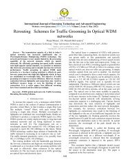
two main parts <strong>of</strong> the pump, the impeller and the volute or<br />
diffuser. The impeller is the rotating part that converts<br />
driver energy into the kinetic energy. The volute or diffuser<br />
is the stationary part that converts the kinetic energy into<br />
pressure energy.<br />
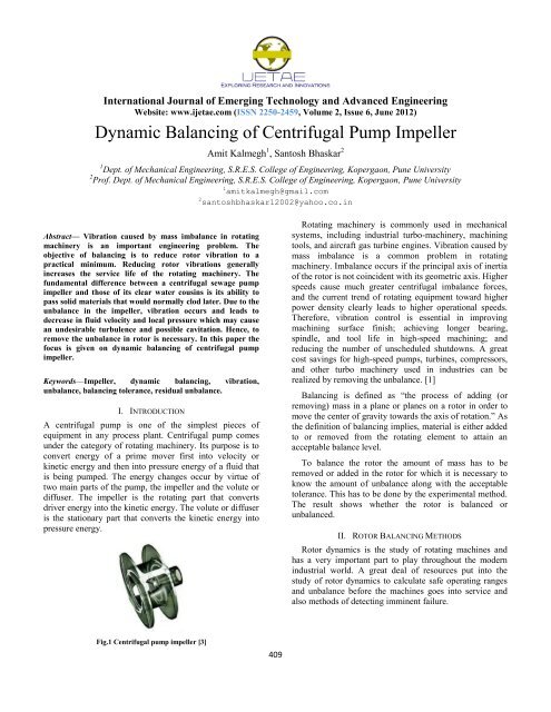
Fig.1 <strong>Centrifugal</strong> pump impeller [3]<br />
1 amitkalmegh@gmail.com<br />
2 santoshbhaskar12002@yahoo.co.in<br />
409<br />
Rotating machinery is commonly used in mechanical<br />
systems, including industrial turbo-machinery, machining<br />
tools, and aircraft gas turbine engines. Vibration caused by<br />
mass imbalance is a common problem in rotating<br />
machinery. Imbalance occurs if the principal axis <strong>of</strong> inertia<br />
<strong>of</strong> the rotor is not coincident with its geometric axis. Higher<br />
speeds cause much greater centrifugal imbalance forces,<br />
and the current trend <strong>of</strong> rotating equipment toward higher<br />
power density clearly leads to higher operational speeds.<br />
Therefore, vibration control is essential in improving<br />
machining surface finish; achieving longer bearing,<br />
spindle, and tool life in high-speed machining; and<br />
reducing the number <strong>of</strong> unscheduled shutdowns. A great<br />
cost savings for high-speed pumps, turbines, compressors,<br />
and other turbo machinery used in industries can be<br />
realized by removing the unbalance. [1]<br />
<strong>Balancing</strong> is defined as ―the process <strong>of</strong> adding (or<br />
removing) mass in a plane or planes on a rotor in order to<br />
move the center <strong>of</strong> gravity towards the axis <strong>of</strong> rotation.‖ As<br />
the definition <strong>of</strong> balancing implies, material is either added<br />
to or removed from the rotating element to attain an<br />
acceptable balance level.<br />
To balance the rotor the amount <strong>of</strong> mass has to be<br />
removed or added in the rotor for which it is necessary to<br />
know the amount <strong>of</strong> unbalance along with the acceptable<br />
tolerance. This has to be done by the experimental method.<br />
The result shows whether the rotor is balanced or<br />
unbalanced.<br />
II. ROTOR BALANCING METHODS<br />
Rotor dynamics is the study <strong>of</strong> rotating machines and<br />
has a very important part to play throughout the modern<br />
industrial world. A great deal <strong>of</strong> resources put into the<br />
study <strong>of</strong> rotor dynamics to calculate safe operating ranges<br />
and unbalance before the machines goes into service and<br />
also methods <strong>of</strong> detecting imminent failure.
<strong>International</strong> Journal <strong>of</strong> Emerging Technology and Advanced Engineering<br />
Website: www.ijetae.com (ISSN 2250-2459, Volume 2, Issue 6, June 2012)<br />
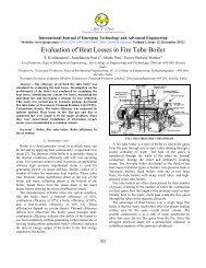
Rotor balancing techniques can be mainly classified as:<br />
On-line balancing methods<br />
Off-line balancing methods<br />
Fig.2 Rotor balancing methods [1]<br />
The <strong>of</strong>f-line rigid rotor balancing method is mostly used<br />
in industrial applications. The rotor is modelled as a rigid<br />
shaft that cannot have elastic deformation during operation.<br />
In this method, any imbalance distribution in a rigid rotor<br />
can be balanced in two different planes. Rigid rotor<br />
balancing is again categories as single plane and two plane<br />
balancing. Here, we are performing two plane balancing on<br />
the pump impeller.<br />
A. Static Unbalance<br />
III. TYPES OF UNBALANCE<br />
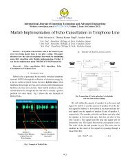
A condition <strong>of</strong> static unbalance exists when the mass<br />
center does not lie on the axis <strong>of</strong> rotation. Static unbalance<br />
is also known as Force Unbalance. As defined, static<br />
unbalance is an ideal condition, it has the additional<br />
condition that the axis <strong>of</strong> rotation be parallel to the central<br />
principal axis - no couple unbalance. [4]<br />
Fig.3 Static unbalance [4]<br />
B. Couple Unbalance<br />
A specific condition that exists when the central<br />
principal axis <strong>of</strong> inertia is not parallel with the axis <strong>of</strong><br />
rotation. As defined, couple unbalance is an ideal<br />
condition. It carries the additional condition that the mass<br />
center lies on the axis <strong>of</strong> rotation – no static unbalance. [4]<br />
410<br />
Fig.4 Couple unbalance [4]<br />
C. <strong>Dynamic</strong> Unbalance<br />
The most general case <strong>of</strong> unbalance in which the central<br />
principal axis is not parallel to and does not intersect the<br />
axis <strong>of</strong> rotation. <strong>Dynamic</strong> unbalance is also referred to as<br />
two plane unbalance, indicating that correction is required<br />
in two planes to fully eliminate dynamic unbalance.<br />
<strong>Dynamic</strong> unbalance captures all the unbalance which exists<br />
in a rotor. This type <strong>of</strong> unbalance can only be measured on<br />
a rotating balancer since it includes couple unbalance.<br />
Since dynamic unbalance is a combination <strong>of</strong> static and<br />
couple unbalance and since static and couple unbalance<br />
have different units, there are no unique units for dynamic<br />
unbalance. It can be expressed as static and couple or in<br />
terms <strong>of</strong> the balance corrections required. [4]<br />
Fig.5 <strong>Dynamic</strong> unbalance [4]<br />
D. Quasi-Static Unbalance<br />
A special form <strong>of</strong> dynamic unbalance in which the static<br />
and couple unbalance vectors lie in the same plane. The<br />
central principal axis intersects the axis <strong>of</strong> rotation, but the<br />
mass center does not lie on the axis <strong>of</strong> rotation. This is the<br />
case where an otherwise balanced rotor is altered (weight<br />
added or removed) in a plane some distance from the mass<br />
center. The alteration creates a static unbalance as well as a<br />
couple unbalance. Conversely, a rotor with quasi-static<br />
unbalance can be balanced with a single correction <strong>of</strong> the<br />
right magnitude in the appropriate plane. [4]<br />
IV. UNBALANCE EFFECT<br />
An unbalanced rotor generates an inertial force<br />
(centrifugal) which increases with the square speed.<br />
Fig.6 Unbalance effect [2]
<strong>International</strong> Journal <strong>of</strong> Emerging Technology and Advanced Engineering<br />
Website: www.ijetae.com (ISSN 2250-2459, Volume 2, Issue 6, June 2012)<br />
F = m.r.ω 2 = U.ω 2<br />
Where,<br />
U = m.r = unbalance [kg.m]<br />
ω = angular speed [rad/s]<br />
ω = 2π.N / 60<br />
Where,<br />
N = revolutions/minute<br />
F = <strong>Centrifugal</strong> force in Newton<br />
The vector unbalance U (multiplied by the factor ω 2 ,<br />
square <strong>of</strong> the angular speed) originates the centrifugal force<br />
F; this means that the load caused by the unbalance<br />
increases with the square <strong>of</strong> the speed (doubling the<br />
running speed the centrifugal force (inertia force) becomes<br />
four times greater). [2]<br />
V. BALANCING TOLERANCES<br />
<strong>International</strong> standard ISO 1940 gives a rule in order to<br />
calculate an acceptable residual unbalance, having<br />
following features:<br />
Gross unbalance deficiencies are avoided<br />
Useless and expensive balancing works are<br />
avoided<br />
For each rotor type, depending on its maximum service<br />
speed the acceptable total residual unbalance per unit <strong>of</strong><br />
mass is calculated [(gr.mm)/kg] (specified residual<br />
unbalance).<br />
The calculated value is the same mass eccentricity:<br />
Where,<br />
E = Mass eccentricity [microns]<br />
U = Unbalance [gr.mm]<br />
M = Rotor mass [kg]<br />
According to ISO 1940 standard, all rotors are classified,<br />
depending on their balancing requirement. <strong>Balancing</strong><br />
quality G is a number which defines the balancing accuracy<br />
required; for instance G = 6.3 means that a normal<br />
balancing is accepted. The maximum service speed is<br />
reported on the horizontal x axis, while the acceptable<br />
specific unbalance (acceptable unbalance per unit <strong>of</strong> mass<br />
or acceptable residual mass eccentricity) is reported on the<br />
vertical y axis.<br />
411<br />
The following formula can be used instead <strong>of</strong> previous<br />
diagram:<br />
Et = (9550 / M).G<br />
Where,<br />
Et [μ] = Total acceptable mass eccentricity<br />
N [RPM] = Maximum service rotor speed<br />
G [mm/s] = <strong>Balancing</strong> quality grade<br />
Total residual accepted unbalance:<br />
U[gr.mm] = Et.M<br />
Where: M [kg] = Rotor mass<br />
Total residual admitted unbalance in grams is m= U/R<br />
Where, R [mm] is the compensation radius. [2]<br />
VI. EXPERIMENTAL METHOD<br />
TABLE I<br />
IMPELLER SPECIFICATIONS<br />
Sr.<br />
No.<br />
Regular Italic<br />
1 <strong>Impeller</strong> type Single vane impeller<br />
2 <strong>Balancing</strong> speed 1450 rpm<br />
3 Length <strong>of</strong> the rotor 210 mm<br />
4 Diameter<br />
impeller<br />
<strong>of</strong> the 310 mm<br />
5 Suction diameter 160 mm<br />
6 Weight <strong>of</strong> the rotor 38.8 kg<br />
7 <strong>Balancing</strong> grade G6.3 (As per Internal<br />
Standard ISO 1940)<br />
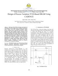
Set up the rotor in the balancer (balancing machine) and<br />
secure it. Mount the rotor vertically on the shaft <strong>of</strong> the<br />
balancer. Make sure that the rotor is place in proper vertical<br />
position. There is no misalignment in the rotor and the shaft<br />
<strong>of</strong> the balancer. Feed the balancing grade in the machine.<br />
Make sure that the rotor is freely rotating. This machine is<br />
the vertical axis semiautomatic machine and has the<br />
capability <strong>of</strong> performing two-plane balancing with required<br />
balancing speed and provides us the exact information <strong>of</strong><br />
unbalance amount and location on the rotor.<br />
Fig.7 Rotor placement on machine
<strong>International</strong> Journal <strong>of</strong> Emerging Technology and Advanced Engineering<br />
Website: www.ijetae.com (ISSN 2250-2459, Volume 2, Issue 6, June 2012)<br />
<strong>Balancing</strong> machine screen provides various details <strong>of</strong> the<br />
plane radius , rotor radius, acceptable unbalance for the<br />
rotor. We can feed the balancing grade (G6.3 for pump<br />
impeller) and machine automatically calculates the<br />
tolerance per plane data and displays on the screen <strong>of</strong> the<br />
balancing machine.<br />
Start the balancer with the balancing speed <strong>of</strong> 1450 rpm<br />
and read out the details on the screen. This specifies the<br />
details about the rotor and the acceptable unbalance. Before<br />
starting mark the location <strong>of</strong> zero on the rotor which should<br />
matches the arrow mark on the balancing machine table.<br />
TABLE III<br />
BALANCING GRADES [5]<br />
<strong>Balancing</strong> Rotor Types<br />
Grades<br />
G 4000 Crankshaft drives <strong>of</strong> rigidly mounted slow marine<br />
diesel engines with uneven number <strong>of</strong> cylinders.<br />
G 1600 Crankshaft drives <strong>of</strong> rigidly mounted large twocycle<br />
engines.<br />
G 630 Crankshaft drives <strong>of</strong> rigidly mounted large fourcycle<br />
engines.<br />
Crankshaft drives <strong>of</strong> elastically mounted marine<br />
diesel engines.<br />
G 250 Crankshaft drives <strong>of</strong> rigidly mounted fast fourcylinder<br />
diesel engines.<br />
G 100 Crankshaft drives <strong>of</strong> fast diesel engines with six or<br />
more cylinders. Complete engines (gas or diesel) for<br />
cars, trucks and locomotives.<br />
G 40 Car wheels, wheel rims, wheel sets, drive shafts.<br />
Crankshaft drives or elastically mounted fast fourcycle<br />
engines (gas or diesel) with six or more<br />
cylinders. Crankshaft drives for engines <strong>of</strong> cars,<br />
trucks or locomotives.<br />
G 16 Drive shafts (propeller shafts, cardan shafts) with<br />
special requirements. Parts <strong>of</strong> crushing machinery.<br />
Parts <strong>of</strong> agricultural machinery. Individual<br />
components <strong>of</strong> engines (gas or diesel) for cars,<br />
trucks and locomotives. Crankshaft drives <strong>of</strong><br />
engines with six or more cylinders under special<br />
requirements. Slurry or dredge pump impeller.<br />
G 6.3 Parts or process plant machines. Marine main<br />
turbine gears (merchant service). Centrifuge drums.<br />
Fans. Assembled aircraft gas turbine rotors. Fly<br />
wheels. <strong>Pump</strong> impellers. Machine tool and general<br />
machinery parts. Normal electrical armatures.<br />
Individual components <strong>of</strong> engines under special<br />
requirements<br />
G 2.5 Gas & steam turbines, including marine main<br />
turbines (merchant service). Rigid turbo-generator<br />
rotors. Rotors. Turbo-compressors. Machine tool<br />
drives. Medium and large electrical armatures with<br />
special requirements. Small electrical armatures.<br />
Turbine driven pumps.<br />
412<br />
G 1 Tape recorder and phonograph drives. Grinding<br />
machine drives. Small electrical armatures with<br />
special requirements<br />
G 0.4 Spindles, disks and armatures <strong>of</strong> precision grinders.<br />
Gyro<br />
TABLE IIIII<br />
BALANCING TOLERANCE [2]<br />
The maximum service speed is reported on the<br />
horizontal x axis, while the acceptable specific unbalance is<br />
reported on the vertical y axis. The formula can be used<br />
instead <strong>of</strong> previous figure.<br />
Et (μ) = (9550/N).G<br />
Et (μ) = 9550/1450×6.3 = 41.50
<strong>International</strong> Journal <strong>of</strong> Emerging Technology and Advanced Engineering<br />
Website: www.ijetae.com (ISSN 2250-2459, Volume 2, Issue 6, June 2012)<br />
Where,<br />
Et[μ] = total acceptable mass eccentricity<br />
N [RPM] = maximum service rotor speed<br />
G [mm/s] = balancing quality (grade)<br />
Total residual accepted unbalance.<br />
Where, M[kg] = Rotor mass<br />
U[gr.mm] = 41.50×38.8<br />
U[gr.mm] = 1610.2<br />
U[gr.mm]=Et.M<br />
Acceptable unbalance per plane<br />
= 1610.2/2=805 gr.mm<br />
Plane 1 acceptable unbalance<br />
= 805/80=10.1 gr<br />
Plane 2 acceptable unbalance<br />
= 805/154=5.2 gr<br />
Wait for some time to stabilize the data on the balancing<br />
machine screen. This data gives us the amount <strong>of</strong><br />
unbalance and the angle <strong>of</strong> the same on the rotor. Once the<br />
data is stabilized, stop the balancer and read the data on the<br />
screen. The screen is mainly divided into two parts, on the<br />
left hand side the data is for plane 1 and on right hand<br />
screen the data is for plane 2. The data is represented in two<br />
colours – red and green. Green colour shows that the<br />
unbalance amount is under acceptable limit whereas the red<br />
colour data shows the unbalance has to be removed as this<br />
exceeds the tolerance limit.<br />
TABLE IVV<br />
BALANCING DATA - I<br />
Sr.<br />
No.<br />
Parameter Plane 1 Plane 2<br />
1 Amount <strong>of</strong> unbalance<br />
[gr]<br />
6.25 30.62<br />
2 Angle [deg] 210 45<br />
3 Radius [mm] 70 153<br />
If the data shows in green, then the rotor if said to be<br />
balanced. Otherwise we need to remove the unbalance<br />
amount from the rotor.<br />
Unbalance Correction Methods:<br />
Addition <strong>of</strong> mass<br />
Removal <strong>of</strong> mass<br />
413<br />
Repeat the same balancing process until the data comes<br />
under the acceptable limit <strong>of</strong> the rotor as per ISO 1940/1<br />
grade G 6.3.<br />
TABLE V<br />
BALANCING DATA - II<br />
Sr.<br />
No.<br />
Parameter Plane 1 Plane 2<br />
1 Amount <strong>of</strong> unbalance<br />
[gr]<br />
5.21 21.01<br />
2 Angle [deg] 212.3 44.5<br />
3 Radius [mm] 70 151<br />
TABLE VI<br />
BALANCING DATA - III<br />
Sr.<br />
No.<br />
Parameter Plane 1 Plane 2<br />
1 Amount <strong>of</strong> unbalance<br />
[gr]<br />
5.15 2.11<br />
2 Angle [deg] 213 45.5<br />
3 Radius [mm] 70 153<br />
TABLE VI shows that the unbalance amount is within<br />
the balancing grade limit. Hence, we can say that the<br />
impeller is balanced as per G6.3 grade.<br />
VII. RESULTS<br />
Rotor dynamics is the study <strong>of</strong> rotating machines and<br />
has a very important part to play throughout the modern<br />
industrial world. The experimental results <strong>of</strong> rotor dynamic<br />
balancing shows the data within acceptable limit as per ISO<br />
1940/1, grade G6.3 for pump impeller.<br />
References<br />
[1] Shiyu Zhou and Jianjun Shi, ―Active <strong>Balancing</strong> and Vibration<br />
Control <strong>of</strong> Rotating Machinery: A Survey‖, The Shock and<br />
Vibration Digest, July 2001, Vol. 33, No. 4, 361-371.<br />
[2] Ing. G. Manni, ―<strong>Balancing</strong> Theory and Applications‖, CEMB S.p.A.<br />
– Via Risogimento, August 1999, Rev. 2.1.<br />
[3] Joe Evans, ―Sewage <strong>Pump</strong> <strong>Impeller</strong> Selection‖, Pacific Liquid & Air<br />
Systems.<br />
[4] Gary K. Grim, John W. Haidler, Bruce J. Mitchell, Jr., ―The Basics<br />
<strong>of</strong> <strong>Balancing</strong>‖, Balance Technology Inc.<br />
[5] Earl M. Halfen, ―Shop <strong>Balancing</strong> Tolerances A Practical Guide‖,<br />
IRD <strong>Balancing</strong>.