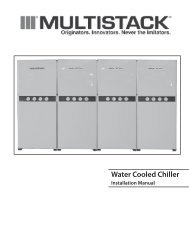
Water Cooled Centrifugal Chiller - Multistack
Water Cooled Centrifugal Chiller - Multistack
Water Cooled Centrifugal Chiller - Multistack

Create successful ePaper yourself
Turn your PDF publications into a flip-book with our unique Google optimized e-Paper software.
<strong>Water</strong> <strong>Cooled</strong> <strong>Centrifugal</strong> <strong>Chiller</strong><br />
Product Data Catalog for MS-80T1
MULTISTACK WATER COOLED CENTRIFUGAL<br />
2<br />
Compressor<br />
Gauges<br />
Condenser <strong>Water</strong><br />
CHILLER MODULES<br />
Cutting Edge Compressor Technology<br />
• MagLev; magnetic levitation<br />
• Oil Free design<br />
• Quieter than typical background noise<br />
• Soft start; pulls only 2 amps at 460V<br />
• Superior part load efficiency<br />
• Integrated VFD control<br />
• Uses environmentally friendly R-134A refrigerant<br />
Superior Dependability<br />
• Multiple independent systems for redundancy<br />
• Comprehensive computer monitoring<br />
• Automatic lead-lag<br />
• Automatic fault recording<br />
Easy Installation<br />
• Compact modules fit through most doorways and into freight elevators<br />
• Modules connect quickly and easily<br />
• Factory charged and run tested<br />
• Micro refrigerant charge compliant with ASHRAE 15 in most cases<br />
High Flexibility<br />
• Service can be performed on a convenient, non-emergency basis<br />
• Install only the capacity required at the time<br />
• Operates only the capacity required by the load<br />
• Integrates fully with building management through BACnet®, ModBus®, N2, or LON<br />
Control Box<br />
Circuit Breaker<br />
(hidden)<br />
Buss Bar<br />
Module Sensor Panel<br />
Chilled <strong>Water</strong>
GEnEral DaTa TablE<br />
MODEl MS-80T1<br />
Compressor Type MagLev <strong>Centrifugal</strong><br />
Dry weight (lbs. each) 265<br />
Normal Capacity (each) 80 Tons<br />
Quantity 1<br />
Oil Charge (pints) N/A<br />
Evaporator Brazed Plate<br />
Weight (lbs. each) 417<br />
<strong>Water</strong> Storage 11.5<br />
Quantity 1<br />
Header System (gallons) 15.1<br />
Condenser Brazed Plate<br />
Weight (lbs. each) 484<br />
<strong>Water</strong> storage (gallons each) 12.6<br />
Quantity 1<br />
Header System (gallons) 15.1<br />
Refrigerant Type R-134A<br />
Refrigerant Charge (lbs./circuit) 45<br />
Number of Circuits 1<br />
Operating Weights (lbs.) 2,651<br />
Shipping Weight (lbs.) 2,195<br />
MULTISTACK WATER COOLED CENTRIFUGAL<br />
DATA & PERFORMANCE TABLES<br />
PErFOrManCE TablE<br />
Single Module: MS-80T1, Entering Condenser <strong>Water</strong> Temperature<br />
75° 80° 85° 90° 95°<br />
Leaving Chilled<br />
<strong>Water</strong> °F<br />
Input<br />
kW<br />
EER<br />
Input<br />
kW<br />
EER<br />
Input<br />
kW<br />
EER<br />
Input<br />
kW<br />
EER<br />
Input<br />
kW<br />
50° F 39.7 23.2 43.6 21.1 47.6 19.3 52.0 17.7 56.8 16.2<br />
48° F 41.6 22.1 45.5 20.2 49.6 18.5 54.1 17.0 59.1 15.6<br />
46° F 43.4 21.2 47.4 19.4 51.7 17.8 56.4 16.3 61.4 15.0<br />
45° F 44.3 20.8 48.4 19.0 52.9 17.4 57.6 16.0 62.8 14.7<br />
44° F 45.4 20.3 49.5 18.6 53.5 17.2 58.9 15.6 64.1 14.4<br />
42° F 47.5 19.4 51.7 17.8 56.5 16.3 61.5 15.0 67.1 13.7<br />
40° F 49.7 18.5 54.3 17.0 59.2 15.5 64.6 14.3 70.6 13.0<br />
All performance at 76.7 tons net capacity.<br />
EER<br />
3
MULTISTACK WATER COOLED CENTRIFUGAL<br />
4<br />
Performance Adjustment Factor<br />
CAPACITY TABLES<br />
Figure 1: Performance adjustment Factor<br />
A. MS-80T1 Condenser<br />
B. MS-80T1 Evaporator<br />
Pressure Drop - PSI<br />
100<br />
90<br />
80<br />
70<br />
60<br />
50<br />
40<br />
30<br />
20<br />
10<br />
9<br />
8<br />
7<br />
6<br />
5<br />
4<br />
50<br />
Chilled <strong>Water</strong> Temperature Drop (°F)<br />
Figure 2: <strong>Water</strong> Pressure Drop<br />
60<br />
70<br />
80<br />
90<br />
100<br />
200<br />
300<br />
Flow Rate - GPM<br />
400<br />
500<br />
600<br />
7 00<br />
800<br />
900<br />
1000<br />
Figure 3: Ethylene Glycol adjustment Factor<br />
Adjustment Factor<br />
Figure 4: Propylene Glycol adjustment Factors<br />
Adjustment Factor<br />
1.70<br />
1.60<br />
1.50<br />
1.40<br />
1.30<br />
1.20<br />
1.10<br />
1.00<br />
.90<br />
.80<br />
Pressure Drop<br />
% Ethylene Glycol<br />
% Propylene Glycol<br />
GPM<br />
KW<br />
Capacity<br />
Pressure Drop<br />
GPM<br />
KW<br />
Capacity
Selection<br />
To select a MULTISTACK MS-80T1 <strong>Centrifugal</strong> <strong>Water</strong> <strong>Cooled</strong> <strong>Chiller</strong>,<br />
the following information is requested:<br />
1. Load in tons of refrigeration.<br />
2. Chilled water temperature drop.<br />
3. Leaving chilled water temperature.<br />
4. Entering condenser water temperature.<br />
Capacity Tables<br />
Capacity tables are based on a 10°F temperature drop through the evaporator<br />
and a capacity of 80 Tons at all chilled and condenser water temperatures.<br />
The module is optimized to provide 80 tons at the maximum efficiency. If the<br />
system load is less than 80 Tons, the chiller will unload to provide the smaller<br />
required capacity at a theoretically higher efficiency. For other than 10°F<br />
temperature drop, apply the respective performance adjustment factors from<br />
Figure 1 to determine the theoretical improvements resulting from a broader<br />
temperature difference.<br />
<strong>Water</strong> Flow rates<br />
Evaporator water flow can be determined as follows:<br />
GPM = (24) (Tons)/Temperature Drop (°F)<br />
Condenser water flow should always be determined using a 10°F temperature<br />
rise as follows:<br />
GPM = 2.4 [Tons + (0.285)(Compressor kW)]<br />
<strong>Water</strong>side Pressure Drop<br />
Evaporator and condenser waterside pressure drops are provided in Figure 2.<br />
To use Figure 2, divide the total water GPM by the number of modules in<br />
the chiller.<br />
Chilled <strong>Water</strong> Selection<br />
Example: System load = 450 tons. Chilled water drop of 12°F. Leaving water<br />
temperature of 45°F. Entering condensed water temperature of 85°F.<br />
1. Use Figure 1 adjustment factor for tons to convert tons to 10°F at<br />
equivalent for use with capacity tables.<br />
Tons = 450/1.012 = 444.7 tons<br />
2. Select the appropriate performance table based on module to be used.<br />
Read the Capacity and kW of a single module at the water temperature<br />
specified.<br />
Capacity = 80.0 tons, kW = 53.6<br />
3. To find the number of modules required, divide equivalent tons required<br />
at 10°F temperature drop by single module capacity from table:<br />
Modules required = 444.7/80= 5.6 or 6 modules<br />
<strong>Chiller</strong> capacity = (80.0)(6) = 480 tons<br />
Power input = (53.6)(6) = 321.6 kW<br />
4. At 12°F evaporator temperature drop, applying Figure 1 performance<br />
adjustment factors result in:<br />
Tons = (480.0)(1.012) = 485.8 tons vs. system load<br />
5. To determine evaporator and condenser water pressure drops, first<br />
determine GPM:<br />
Evaporator GPM = (24)(485.8)/12 = 971.6 GPM<br />
Condenser GPM = 2.4[485.8 + (0.285)(321.6)] = 1385.9 GPM<br />
MULTISTACK WATER COOLED CENTRIFUGAL<br />
SELECTION GUIDE<br />
6. With a six-module chiller, evaporator and condenser pressure drops are<br />
read from Figure 2 as follows:<br />
Evaporator = GPM/modules = 971.6/6 = 162 GPM<br />
Pressure drop = 4.3 feet<br />
Condenser = GPM/modules = 1385.9/6 = 231 GPM<br />
Pressure drop = 7.2 feet<br />
Note: The above calculations represent theoretical changes in<br />
performance based on well established empirical data. In reality,<br />
these calculated points may never be observed in operation since<br />
the MS-80T1 will modulate to meet the required capacity and<br />
achieve its leaving chilled water setpoint.<br />
Operation with Glycol<br />
Ethylene glycol adjustment factors (Figure 3) should be used to adjust performance,<br />
depending on the percent of glycol used in the evaporator circuit. The<br />
factors in Table 3 are based on a 10°F change in fluid temperature through<br />
the evaporators. Capacity and kW should be obtained by extrapolating no<br />
more than 10°F from the lowest leaving chilled water temperature shown in<br />
the capacity tables. MULTISTACK should be contacted if leaving glycol temperatures<br />
below 40°F are required. Adjustment factors for propylene glycol<br />
are shown in Figure 4 and are used in the same way given in the following<br />
example.<br />
Glycol Selection Example<br />
Determine Capacity, GPM, Pressure Drop and kW for a MS-80T1 module<br />
cooling 30% ethylene glycol from 50°F to 40°F, with an entering condensing<br />
temperature of 85°F and 100% water.<br />
1. By extrapolating from the Performance Tables:<br />
Capacity: 80.0 tons, kW: 59.4<br />
2. Evaporator water flow and pressure drops are determined for<br />
water as in the previous example.<br />
Evaporator GPM = (24)(80)/10 = 192 GPM<br />
Evaporator pressure drop = 6 feet<br />
3. To convert performance for water to performance with ethylene<br />
glycol, read adjustment factors from Figure 3 at 30% glycol.<br />
Capacity adjustment 0.94<br />
kW adjustment 0.99<br />
Evaporator GPM adjustment 1.10<br />
Pressure drop adjustment 1.22<br />
4. Calculate performance with 30% ethylene glycol by multiplying<br />
performance for water by adjustment factors:<br />
Capacity 80.0 x 0.94 = 75.2 tons<br />
kW 59.4 x 0.99 = 58.8 kW<br />
GPM 192 x 1.10 = 211.2 GPM<br />
Pressure drop 6.0 x 1.22 = 7.32 ft of water<br />
5. To determine condenser water pressure drops, first<br />
determine GPM.<br />
6. Condenser pressure drops are read from Figure 2 as follows:<br />
Condenser pressure drop = 6.5 feet<br />
5
MULTISTACK WATER COOLED CENTRIFUGAL<br />
6<br />
End Elevation<br />
CHILLER
ECW<br />
LCW<br />
ECHW<br />
LCHW<br />
FS1<br />
FS2<br />
CAR<br />
FLR<br />
CPR<br />
DRSV<br />
EX1<br />
EX2<br />
EX4<br />
RESET SIGNAL RS+<br />
RESET SIGNAL RS-<br />
COMMON<br />
MS1<br />
MS2<br />
MASTER CONTROL<br />
System Wire and Fuse Sizing<br />
Model no. Volts/Hz/PH Tons<br />
Compressor<br />
rla lra<br />
MS-80T1 460/60/3 80 96 132<br />
G<br />
Wiring Sizing Fuse Sizing<br />
(MCA=minimum circuit ampacity) (MF = maximum fuse size)<br />
MCA = (1.25 x RLA1*) + RLA2+RLA3 MF = (2.25 x RLA1*) + RLA2 + RLA3<br />
Notes:<br />
1. *RLA1 = RLA of the largest motor in the system. RLA2 & RLA3 = RLA of other motors in the system.<br />
2. Wire sizing is based on National Electrical Code (NEC) rating for 75°C wire, with 3 wires per conduit.<br />
3. Wiring distance from branch circuit shall not exceed 100 feet.<br />
MULTISTACK WATER COOLED CENTRIFUGAL<br />
ELECTRICAL DATA<br />
lEGEnD<br />
1. Components and wiring by others. (18 AWG Min. wire).<br />
2. Inputs to terminals 4 through 8 of TB11 must be wired closed if not<br />
used.<br />
3. External inputs (Closed to operate).<br />
EX1 Manual reset required to resume operation.<br />
EX2 Auto reset (Remote start/stop).<br />
EX4 Auto reset (Power phase monitor input).<br />
FS1 Flow switch (Chilled water).<br />
FS2 Flow switch (Condenser water).<br />
MS1 Aux. interlock (Chilled water pump starter).<br />
MS2 Aux. interlock (Condenser water pump starter).<br />
RS+ Reset signal (Software selectable 0-10VDC, 4-20mA).<br />
RS- Reset signal (Software selectable 0-10VDC, 4-20mA).<br />
4. External outputs.<br />
CAR Customer alarm relay (24 VAC, 5 VA max).<br />
CPR Condenser pump relay (24 VAC, 5 VA max).<br />
FLR Full load relay (24 VAC, 5 VA max).<br />
DRSV Debris removal solenoid valve (24 VAC, 6 W, 16VA)<br />
Max of (2) DRSV in this circuit.<br />
5. Sensor Inputs<br />
ECW Entering condenser water.<br />
LCW Leaving condenser water.<br />
ECHW Entering chilled water.<br />
LCHW Leaving chilled water.<br />
For additional information, see installation manual and master control user<br />
manual.<br />
MCa<br />
3 Conductor<br />
1 Conduit<br />
6 Conductor<br />
2 Conduit<br />
50 8 –<br />
65 6 –<br />
85 4 –<br />
100 3 –<br />
115 2 –<br />
130 1 –<br />
150 1/0 –<br />
175 2/0 –<br />
200 3/0 –<br />
230 4/0 –<br />
255 250 MCM –<br />
285 300 MCM 1/0<br />
300 – 2/0<br />
350 – 3/0<br />
400 – 4/0<br />
460 – 4/0<br />
500 – 250 MCM<br />
7
MULTISTACK WATER COOLED CENTRIFUGAL<br />
8<br />
SCHEMATICS<br />
required Chilled <strong>Water</strong> Piping<br />
<strong>Multistack</strong> <strong>Chiller</strong><br />
Pressure<br />
Taps<br />
Supplied and<br />
installed by<br />
<strong>Multistack</strong>.<br />
1/2” Sensor<br />
Pockets<br />
Supplied by<br />
<strong>Multistack</strong>.<br />
Installation of sensor<br />
pocket (Weld-a-Let)<br />
is recommended<br />
at 30” from end of<br />
chiller; supplied and<br />
installed by others.<br />
<strong>Chiller</strong> Isolation Valve<br />
Supplied and installed by others.<br />
Condenser Schematic with Head Pressure Control<br />
<strong>Multistack</strong> <strong>Chiller</strong><br />
Pressure<br />
Taps<br />
Supplied and<br />
installed by<br />
<strong>Multistack</strong>.<br />
Standard “Y”<br />
Strainer<br />
Supplied and<br />
installed by<br />
others. Note:<br />
Select strainer<br />
based on water<br />
quality.<br />
1/2” Sensor Condenser<br />
Pockets Isolation<br />
Supplied by<br />
Valves<br />
<strong>Multistack</strong>.<br />
Supplied and<br />
Installation of installed by<br />
sensor pocket<br />
others.<br />
(Weld-a-Let) is<br />
recommended at<br />
30” from end of<br />
chiller; supplied and<br />
installed by others.<br />
Standard “Y”<br />
Strainer<br />
Supplied and<br />
installed by<br />
others. Note:<br />
Select strainer<br />
based on water<br />
quality.<br />
Strainer<br />
Isolation<br />
Valve<br />
Supplied and<br />
installed by<br />
others.<br />
Flow Switch<br />
Supplied and<br />
installed by<br />
others.<br />
Flow Switch<br />
Supplied and<br />
installed by<br />
others.<br />
Strainer<br />
Isolation<br />
Valve<br />
Supplied and<br />
installed by<br />
others.<br />
Chilled <strong>Water</strong><br />
Pump<br />
Supplied and<br />
installed by others.<br />
Condenser<br />
<strong>Water</strong> Pump<br />
Supplied and<br />
installed by<br />
others.<br />
From building<br />
load<br />
To building<br />
load<br />
To cooling<br />
tower<br />
3-Way<br />
Condenser<br />
by-Pass Valve<br />
Recommended,<br />
supplied and<br />
installed in the<br />
building by others.<br />
From cooling<br />
tower
26”<br />
minimum<br />
64”<br />
Recommended<br />
service clearance<br />
Union 3/4” F,P,T<br />
(4) Blank ends<br />
Drain Hose<br />
Solenoid<br />
valve (N.C.)<br />
1-1/4” N.P.S.<br />
full port<br />
38”<br />
1-1/2”<br />
4”<br />
DDRS–210A<br />
42” Minimum required clearance<br />
42” Recommended service clearance<br />
Numbers of Modules x 32”+3”<br />
Rail length: Numbers of Modules x 32”+8”<br />
4” x 4: x 1/8”- wall structural<br />
foot rails resting on waffle vibration<br />
isolators 32” center-tocenter<br />
(supplied by others).<br />
MULTISTACK WATER COOLED CENTRIFUGAL<br />
SCHEMATICS<br />
9”<br />
Minimum size vibration<br />
isolators 4” x 4” x 3/8”<br />
Maximum load 50 P.S.L.<br />
20”<br />
32” 1-1/2”<br />
Main power<br />
connection<br />
modules (may<br />
be on either<br />
end)<br />
32”<br />
Recommended service<br />
clearance<br />
22”<br />
Pressure taps<br />
32-5/8”<br />
Drain with<br />
hose bibb (2)<br />
Condenser water and<br />
chilled water connections<br />
4 stubs, each 8” SCH, 40<br />
steel pipe for butt welds or<br />
victaulic connections.<br />
9
MULTISTACK WATER COOLED CENTRIFUGAL<br />
10<br />
MECHANICAL SPECIFICATION<br />
System Description<br />
<strong>Chiller</strong> shall incorporate two stage centrifugal Compressor with<br />
magnetic bearings and consist of single 80 ton refrigerant circuits.<br />
Each refrigerant circuit shall consist of an individual compressor,<br />
condenser, evaporator, electronic expansion valve, and control<br />
system. Each circuit shall be constructed to be independent of other<br />
circuits from a refrigeration and electrical standpoint. The chiller<br />
system must be able to produce chilled water even in the event of a<br />
failure of one or more refrigerant circuits. Circuits shall not contain<br />
more than 55 lb. of refrigerant.<br />
General<br />
1. <strong>Chiller</strong> Modules shall be ETLC/US listed in accordance with UL<br />
Standard 1995, CSA Standard C22.2#236, and bear the ASME<br />
UM stamp on all heat exchangers.<br />
2. Modules shall ship wired and charged with refrigerant. All<br />
modules shall be factory run tested prior to shipment.<br />
3. Compressors, heat exchangers, piping and controls shall be<br />
mounted on a heavy gauge steel frame. Electrical controls,<br />
and associated components for each module shall be mounted<br />
within that module.<br />
Chilled and Condenser <strong>Water</strong> Mains<br />
Each module shall include supply and return mains for both chilled<br />
and condenser water. Grooved end connections are provided for<br />
interconnection to eight inch standard (8.625 inch outside diameter)<br />
piping with Victaulic type couplings.<br />
Evaporators and Condensers:<br />
Each evaporator and condenser shall be brazed plate heat exchangers<br />
constructed of 316 stainless steel; designed, tested, and stamped<br />
in accordance with ASME code for 450 psig working pressure on the<br />
evaporator and 450 psig working pressure on the condenser. Both<br />
the condenser and evaporator heat exchanger shall be mounted<br />
below the compressor, to eliminate the effect of migration of<br />
refrigerant to the cold evaporator with consequent liquid slugging<br />
on start-up.<br />
Compressor<br />
1. Unit shall have a direct drive oil-free two-stage semihermetic<br />
centrifugal compressor complete with an active / passive<br />
magnetic bearing system. Casing shall be constructed from<br />
aluminum and shall not weigh more than 300 lbs each. The<br />
electronic soft starters, compressor controls, inverter power<br />
electronics, bearing and motor control shall be fully integrated<br />
into the compressor and shall be digitally controlled. The<br />
magnetic bearing system must be fully protected in the case of<br />
a power outage with its own inbuilt power generation system.<br />
2. The impeller shall be statically and dynamically balanced. The<br />
compressor shall be vibration tested and not exceed a level of<br />
0.14 IPS.<br />
3. The capacity control should primarily be achieved by varying<br />
the compressors operating speed and a movable inlet guide<br />
vane shall only be used in the case of a surge or choke condition<br />
arising during normal operation. The moveable inlet<br />
guide vane shall be of the electromechanical type.<br />
4. Bearing System: The compressor shall use an oil-free bearing<br />
system of the digitally controlled homo-polo magnetic<br />
bearing type. The bearings shall have an fully integrated back<br />
up bearing system and shall have a self generating power<br />
system so that the bearings shall be able to stay levitated in<br />
the case of a power failure. No sump heater is to be required.<br />
The bearing system shall use no more than 500 watts of<br />
energy during its normal operation and it must also have an<br />
auto balance capability in the case of any external vibration<br />
or out of balance event occurring.<br />
5. Prime Mover: A direct drive synchronous permanent magnet<br />
brushless DC motor of the hermetic type of sufficient size<br />
to efficiently fulfill compressor horsepower requirements.<br />
Motor shall be liquid refrigerant cooled with internal thermal<br />
overload protection devices embedded in the winding of each<br />
phase.<br />
6. Motor Starter: The main motor starter is to be fully integrated<br />
into the compressor and shall be of the softstart type with a<br />
maximum starting current of 20% of the full load current of<br />
the compressor. It must be fully integrated with the motors<br />
variable speed control system and it must be factory tested<br />
during the run test of the unit.<br />
7. Variable Frequency Drive: The chiller shall be equipped with a<br />
fully integrated Variable Frequency Drive (VFD) to automatically<br />
regulate compressor speed in response to cooling load<br />
and compressor pressure lift. The chiller control shall coordinate<br />
compressor speed and guide vane position to optimize<br />
chiller efficiency.<br />
a. Digital regulator shall provide V/Hz control.<br />
b. The VFD shall have 110% continuous overload of<br />
continuous amp rating with no time limit, PWM (pulse<br />
width modulated output, IGBT (insulated gate bipolar<br />
transistors) power technology, full power rating at 2kHz,<br />
DC bus inductor (choke), and wireless construction. The<br />
inverter unit shall be refrigerant cooled and shall be fully<br />
integrated into the compressor package.<br />
Central Control System<br />
1. Scheduling of the various compressors shall be performed by a<br />
microprocessor based control system (Master Controller). A new<br />
lead compressor is selected every 24 hours to assure even distribution<br />
of compressor run time.
2. The Master Controller shall monitor and report the following on<br />
each refrigeration system:<br />
a. Discharge Pressure Fault<br />
b. Suction Pressure Fault<br />
c. Compressor Winding Temperature<br />
d. Suction Temperature<br />
e. Evaporator Leaving Chilled <strong>Water</strong> Temp.<br />
3. The Master Controller shall monitor and report the following<br />
system parameters:<br />
a. Chilled <strong>Water</strong> Entering and Leaving Temperature<br />
b. Condenser <strong>Water</strong> Entering and Leaving Temperature<br />
c. Chilled <strong>Water</strong> and Condenser <strong>Water</strong> Flow<br />
4. An out of tolerance indication from these controls or sensors<br />
shall cause a fault indication at the Master Controller and<br />
shutdown of that compressor with the transfer of load requirements<br />
to the next available compressor. In the case of a System<br />
Fault, the entire chiller will be shut down. When a fault occurs,<br />
the Master Controller shall record conditions at the time of the<br />
fault and store the data for recall. This information shall be<br />
capable of being recalled through the keypad of the Master<br />
Controller and displayed on the Master Controller’s 2 line by 40<br />
character back-lit LCD. A history of faults shall be maintained<br />
including date and time of day of each fault (up to the last 20<br />
occurrences).<br />
5. Individual monitoring of leaving chilled water temperatures<br />
from each refrigeration system shall be programmed to protect<br />
against freeze-up.<br />
Master Controller<br />
Stages and monitors the status of up to 8 modules. Provides<br />
interface with all system variables and set points.<br />
lCD Display<br />
4X20 character backlit LCD displays system and chiller<br />
variables. A complete picture of both compressor and chiller<br />
system performance is available at the display. This includes<br />
but is not limited to refrigerant temperatures and pressures,<br />
water temperatures, compressor speeds (actual and desired),<br />
detailed fault information, compressor run hours, and theoretical<br />
system capacity.<br />
MULTISTACK WATER COOLED CENTRIFUGAL<br />
MECHANICAL SPECIFICATION<br />
6. The control system shall monitor entering and leaving chilled<br />
water temperatures to determine system load and select the<br />
number of compressor circuits required to operate. Response<br />
times and set points shall be adjustable. The system shall<br />
provide for variable time between compressor sequencing and<br />
temperature sensing, so as to fine tune the chiller to different<br />
existing building conditions.<br />
7. Each module shall have a dedicated sub-controller and<br />
handoff/ auto switch such that in the event of loss of communications<br />
with the master controller, each module is capable of<br />
operating independently to meet chilled water load.<br />
Power Connections<br />
<strong>Chiller</strong> shall have a single point power connection and external<br />
inputs and outputs to be compatible with the building management<br />
system. Inputs/Outputs include:<br />
1. Remote Start/Stop<br />
2. Cooling Alarm<br />
Additionally, chiller shall be integrateable with building management<br />
systems through BacNet®, ModBus®, N2, or LON.<br />
Inlet Headers<br />
Each inlet header shall incorporate a built in 30-mesh in-line<br />
strainer system to prevent heat exchanger fouling. This system<br />
shall include an automatic self-cleaning debris blow down system<br />
(MultiFlush) for on-line cleaning of the in-line strainers.<br />
System Interface Portal<br />
Integrates chiller with building management<br />
system through BacNet®, ModBus®, N2, or LON.<br />
Module Controller and Hand-Off/<br />
auto Control<br />
Receives direction from the master controller and<br />
provides the capability of standalone operation<br />
if the master controller fails or if communication<br />
with the master controller is lost. Each module<br />
controller communicates directly with its module’s<br />
MagLev compressor through ModBus® providing<br />
a more redundant means of multiple compressor<br />
control.<br />
11
MULTISTACK WATER COOLED CENTRIFUGAL<br />
COMPRESSOR<br />
Inverter speed control<br />
Permanent magnet motor<br />
Motor and bearing control<br />
Two-stage, direct-drive,<br />
hermetic centrifugal<br />
compressor<br />
Inlet guide vanes<br />
1065 Maple Avenue Sparta, WI 54656 • Phone: (608)366-2400 • Fax: (608)366-2450<br />
www.multistack.com<br />
sm<br />
F110_1010