SLUDGE DEWATERING - SNF Group
SLUDGE DEWATERING - SNF Group
SLUDGE DEWATERING - SNF Group

Create successful ePaper yourself
Turn your PDF publications into a flip-book with our unique Google optimized e-Paper software.
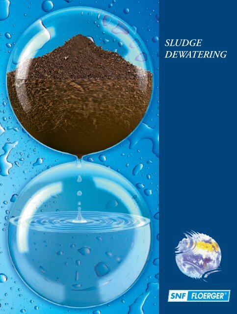
<strong>SLUDGE</strong><br />
<strong>DEWATERING</strong>
2<br />
i n d e x<br />
Today, the treatment of water is a well-known process and is executed by state of the art techniques.<br />
The sludge resulting from this process represents the next challenge for the water treatment industry, in<br />
particular the minimizing of its volume.<br />
This Sludge Dewatering handbook will present the key parameters to take into account in order to optimize<br />
sludge treatment with <strong>SNF</strong> Floerger’s organic polymers.<br />
INDEX<br />
1<br />
2<br />
3<br />
Sludge characterisation: . . . . . . . . . . . . . . . . . . . . . . . . . . . . . . . . . . . . . . . . . . . . . . . . . . .4<br />
1.1. Origin of the sludge: . . . . . . . . . . . . . . . . . . . . . . . . . . . . . . . . . . . . . . . . . . . . . . . . . . . . . . . . . .4<br />
1.2. The different types of sludge: . . . . . . . . . . . . . . . . . . . . . . . . . . . . . . . . . . . . . . . . . . . . . . . . . . . .4<br />
1.2.1. Primary sludge: . . . . . . . . . . . . . . . . . . . . . . . . . . . . . . . . . . . . . . . . . . . . . . . . . . . . . . . . . . . . .4<br />
1.2.2. Biological sludge: . . . . . . . . . . . . . . . . . . . . . . . . . . . . . . . . . . . . . . . . . . . . . . . . . . . . . . . . . . .4<br />
1.2.3. Mixed sludge: . . . . . . . . . . . . . . . . . . . . . . . . . . . . . . . . . . . . . . . . . . . . . . . . . . . . . . . . . . . . . .5<br />
1.2.4. Digested sludge: . . . . . . . . . . . . . . . . . . . . . . . . . . . . . . . . . . . . . . . . . . . . . . . . . . . . . . . . . . . .5<br />
1.2.5. Physico-chemical sludge: . . . . . . . . . . . . . . . . . . . . . . . . . . . . . . . . . . . . . . . . . . . . . . . . . . .6<br />
1.2.6 Mineral sludge: . . . . . . . . . . . . . . . . . . . . . . . . . . . . . . . . . . . . . . . . . . . . . . . . . . . . . . . . . . . . .6<br />
1.3. Parameters that influence the dewatering abilities of sludge: . . . . . . . . . . . . . . . . . . . . . . . .6<br />
1.3.1. Concentration (g/l): . . . . . . . . . . . . . . . . . . . . . . . . . . . . . . . . . . . . . . . . . . . . . . . . . . . . . . . .6<br />
1.3.2. The organic matter content (%): . . . . . . . . . . . . . . . . . . . . . . . . . . . . . . . . . . . . . . . . . . . . .6<br />
1.3.3. The colloidal nature of the sludge: . . . . . . . . . . . . . . . . . . . . . . . . . . . . . . . . . . . . . . . . . .6<br />
Dewatering aids: . . . . . . . . . . . . . . . . . . . . . . . . . . . . . . . . . . . . . . . . . . . . . . . . . . . . . . . . . .7<br />
2.1. Mineral chemicals: . . . . . . . . . . . . . . . . . . . . . . . . . . . . . . . . . . . . . . . . . . . . . . . . . . . . . . . . . . . . . . 7<br />
2.1.1. Iron salts: . . . . . . . . . . . . . . . . . . . . . . . . . . . . . . . . . . . . . . . . . . . . . . . . . . . . . . . . . . . . . . . . .7<br />
2.1.2. Lime: . . . . . . . . . . . . . . . . . . . . . . . . . . . . . . . . . . . . . . . . . . . . . . . . . . . . . . . . . . . . . . . . . . . . . .7<br />
2.2. Organic chemicals: . . . . . . . . . . . . . . . . . . . . . . . . . . . . . . . . . . . . . . . . . . . . . . . . . . . . . . . . . . . . . .8<br />
2.2.1. Flocculation mechanism: . . . . . . . . . . . . . . . . . . . . . . . . . . . . . . . . . . . . . . . . . . . . . . . . . . .8<br />
2.2.2. Destabilized particles: . . . . . . . . . . . . . . . . . . . . . . . . . . . . . . . . . . . . . . . . . . . . . . . . . . . . .8<br />
2.3. Parameters of the organic chemicals that will influence dewatering: . . . . . . . . . . . . . . . . .9<br />
2.3.1. The type of charge ( + or - ): . . . . . . . . . . . . . . . . . . . . . . . . . . . . . . . . . . . . . . . . . . . . . . . .9<br />
2.3.2. The charge density (%): . . . . . . . . . . . . . . . . . . . . . . . . . . . . . . . . . . . . . . . . . . . . . . . . . . . . .9<br />
2.3.3. The molecular weight (MW): . . . . . . . . . . . . . . . . . . . . . . . . . . . . . . . . . . . . . . . . . . . . . . .10<br />
2.3.4. The molecular structure: . . . . . . . . . . . . . . . . . . . . . . . . . . . . . . . . . . . . . . . . . . . . . . . . . .10<br />
2.3.5. The type of monomer: . . . . . . . . . . . . . . . . . . . . . . . . . . . . . . . . . . . . . . . . . . . . . . . . . . . .10<br />
Dynamic thickening: . . . . . . . . . . . . . . . . . . . . . . . . . . . . . . . . . . . . . . . . . . . . . . . . . . . . . 11<br />
3.1. Flotation: . . . . . . . . . . . . . . . . . . . . . . . . . . . . . . . . . . . . . . . . . . . . . . . . . . . . . . . . . . . . . . . . . . . . . . 11<br />
3.1.1. Indirect flotation: . . . . . . . . . . . . . . . . . . . . . . . . . . . . . . . . . . . . . . . . . . . . . . . . . . . . . . . . . 12<br />
3.1.2. Direct flotation: . . . . . . . . . . . . . . . . . . . . . . . . . . . . . . . . . . . . . . . . . . . . . . . . . . . . . . . . . . . 11<br />
3.1.3. Sludge conditioning before flotation: . . . . . . . . . . . . . . . . . . . . . . . . . . . . . . . . . . . . . . . 12<br />
3.2. Thickening table: . . . . . . . . . . . . . . . . . . . . . . . . . . . . . . . . . . . . . . . . . . . . . . . . . . . . . . . . . . . . . . . 12<br />
3.2.1. Operating principle: . . . . . . . . . . . . . . . . . . . . . . . . . . . . . . . . . . . . . . . . . . . . . . . . . . . . . . . 13<br />
3.2.2. Sludge conditioning before thickening table: . . . . . . . . . . . . . . . . . . . . . . . . . . . . . . . . 13<br />
3.3. Thickening drum, screw drum: . . . . . . . . . . . . . . . . . . . . . . . . . . . . . . . . . . . . . . . . . . . . . . . . . . . 14<br />
3.3.1. Operating principle: . . . . . . . . . . . . . . . . . . . . . . . . . . . . . . . . . . . . . . . . . . . . . . . . . . . . . . . 14<br />
3.3.2. Sludge conditioning before thickening drum: . . . . . . . . . . . . . . . . . . . . . . . . . . . . . . . . 14<br />
3.4. Centrifuge: . . . . . . . . . . . . . . . . . . . . . . . . . . . . . . . . . . . . . . . . . . . . . . . . . . . . . . . . . . . . . . . . . . . . 15<br />
3.4.1. Operating principle: . . . . . . . . . . . . . . . . . . . . . . . . . . . . . . . . . . . . . . . . . . . . . . . . . . . . . . . 15<br />
3.4.2. Sludge conditioning before centrifuge: . . . . . . . . . . . . . . . . . . . . . . . . . . . . . . . . . . . . . . 15
4<br />
5<br />
6<br />
Belt filter dewatering: . . . . . . . . . . . . . . . . . . . . . . . . . . . . . . . . . . . . . . . . . . . . . . . . . . . 16<br />
4.1. Equipment description and operating principle: . . . . . . . . . . . . . . . . . . . . . . . . . . . . . . . . . . . 16<br />
4.2. Lab tests: . . . . . . . . . . . . . . . . . . . . . . . . . . . . . . . . . . . . . . . . . . . . . . . . . . . . . . . . . . . . . . . . . . . . . . 17<br />
4.2.1. Sampling: . . . . . . . . . . . . . . . . . . . . . . . . . . . . . . . . . . . . . . . . . . . . . . . . . . . . . . . . . . . . . . . . . 17<br />
4.2.2. Laboratory equipment: . . . . . . . . . . . . . . . . . . . . . . . . . . . . . . . . . . . . . . . . . . . . . . . . . . . . 17<br />
4.2.3. Test procedures: . . . . . . . . . . . . . . . . . . . . . . . . . . . . . . . . . . . . . . . . . . . . . . . . . . . . . . . . . . . 18<br />
4.2.4. Parameters to check and analysis of the results: . . . . . . . . . . . . . . . . . . . . . . . . . . . . 18<br />
4.3. Plant trials: . . . . . . . . . . . . . . . . . . . . . . . . . . . . . . . . . . . . . . . . . . . . . . . . . . . . . . . . . . . . . . . . . . . . 19<br />
4.3.1. Setting up a trial: . . . . . . . . . . . . . . . . . . . . . . . . . . . . . . . . . . . . . . . . . . . . . . . . . . . . . . . . . 19<br />
4.3.2. Parameters to follow and analysis of results: . . . . . . . . . . . . . . . . . . . . . . . . . . . . . . . 19<br />
4.4. Optimizing belt filters: . . . . . . . . . . . . . . . . . . . . . . . . . . . . . . . . . . . . . . . . . . . . . . . . . . . . . . . . . 19<br />
4.4.1. Bad drainage: . . . . . . . . . . . . . . . . . . . . . . . . . . . . . . . . . . . . . . . . . . . . . . . . . . . . . . . . . . . . 20<br />
4.4.2. Sludge creeping: . . . . . . . . . . . . . . . . . . . . . . . . . . . . . . . . . . . . . . . . . . . . . . . . . . . . . . . . . . 20<br />
4.4.3. Low cake dryness: . . . . . . . . . . . . . . . . . . . . . . . . . . . . . . . . . . . . . . . . . . . . . . . . . . . . . . . . . 21<br />
4.4.4. Summary of the adjustable parameters: . . . . . . . . . . . . . . . . . . . . . . . . . . . . . . . . . . . . 21<br />
Centrifuge dewatering: . . . . . . . . . . . . . . . . . . . . . . . . . . . . . . . . . . . . . . . . . . . . . . . . . . 22<br />
5.1. Equipment description and operating principle: . . . . . . . . . . . . . . . . . . . . . . . . . . . . . . . . . . 22<br />
5.2. Lab tests: . . . . . . . . . . . . . . . . . . . . . . . . . . . . . . . . . . . . . . . . . . . . . . . . . . . . . . . . . . . . . . . . . . . . . . 23<br />
5.2.1. Sampling: . . . . . . . . . . . . . . . . . . . . . . . . . . . . . . . . . . . . . . . . . . . . . . . . . . . . . . . . . . . . . . . . 23<br />
5.2.2. Laboratory equipment: . . . . . . . . . . . . . . . . . . . . . . . . . . . . . . . . . . . . . . . . . . . . . . . . . . . 24<br />
5.2.3. Test procedures: . . . . . . . . . . . . . . . . . . . . . . . . . . . . . . . . . . . . . . . . . . . . . . . . . . . . . . . . . . 24<br />
5.2.4. Parameters to check and analysis of the results: . . . . . . . . . . . . . . . . . . . . . . . . . . . . 25<br />
5.3. Plant trials: . . . . . . . . . . . . . . . . . . . . . . . . . . . . . . . . . . . . . . . . . . . . . . . . . . . . . . . . . . . . . . . . . . . . 25<br />
5.3.1. Setting up a trial: . . . . . . . . . . . . . . . . . . . . . . . . . . . . . . . . . . . . . . . . . . . . . . . . . . . . . . . . . 25<br />
5.3.2. Parameters to follow and analysis of results: . . . . . . . . . . . . . . . . . . . . . . . . . . . . . . . 25<br />
5.4. Optimizing centrifuges: . . . . . . . . . . . . . . . . . . . . . . . . . . . . . . . . . . . . . . . . . . . . . . . . . . . . . . . . . 26<br />
5.4.1. Black centrate: . . . . . . . . . . . . . . . . . . . . . . . . . . . . . . . . . . . . . . . . . . . . . . . . . . . . . . . . . . . 26<br />
5.4.2. Gray, foaming centrate: . . . . . . . . . . . . . . . . . . . . . . . . . . . . . . . . . . . . . . . . . . . . . . . . . . . 26<br />
5.4.3. Low cake dryness: . . . . . . . . . . . . . . . . . . . . . . . . . . . . . . . . . . . . . . . . . . . . . . . . . . . . . . . . 27<br />
5.4.4. Summary of the adjustable parameters: . . . . . . . . . . . . . . . . . . . . . . . . . . . . . . . . . . . 27<br />
Frame filter press dewatering: . . . . . . . . . . . . . . . . . . . . . . . . . . . . . . . . . . . . . . . . . . . . 28<br />
6.1. Equipment description and operating principle: . . . . . . . . . . . . . . . . . . . . . . . . . . . . . . . . . . 28<br />
6.2. Lab tests: . . . . . . . . . . . . . . . . . . . . . . . . . . . . . . . . . . . . . . . . . . . . . . . . . . . . . . . . . . . . . . . . . . . . . . 30<br />
6.2.1. Sampling: . . . . . . . . . . . . . . . . . . . . . . . . . . . . . . . . . . . . . . . . . . . . . . . . . . . . . . . . . . . . . . . . 30<br />
6.2.2. Laboratory equipment: . . . . . . . . . . . . . . . . . . . . . . . . . . . . . . . . . . . . . . . . . . . . . . . . . . . 30<br />
6.2.3. Test procedures: . . . . . . . . . . . . . . . . . . . . . . . . . . . . . . . . . . . . . . . . . . . . . . . . . . . . . . . . . . 30<br />
6.2.4. Parameters to check and analysis of the results: . . . . . . . . . . . . . . . . . . . . . . . . . . . . 31<br />
6.3. Plant trials: . . . . . . . . . . . . . . . . . . . . . . . . . . . . . . . . . . . . . . . . . . . . . . . . . . . . . . . . . . . . . . . . . . . . 32<br />
6.3.1. Setting up a trial: . . . . . . . . . . . . . . . . . . . . . . . . . . . . . . . . . . . . . . . . . . . . . . . . . . . . . . . . . 32<br />
6.3.2. Parameters to follow and analysis of results: . . . . . . . . . . . . . . . . . . . . . . . . . . . . . . . 32<br />
6.4. Optimizing frame filter press: . . . . . . . . . . . . . . . . . . . . . . . . . . . . . . . . . . . . . . . . . . . . . . . . . . . 32<br />
6.4.1. Sticky cakes: . . . . . . . . . . . . . . . . . . . . . . . . . . . . . . . . . . . . . . . . . . . . . . . . . . . . . . . . . . . . . . 33<br />
6.4.2. Cloth plugging: . . . . . . . . . . . . . . . . . . . . . . . . . . . . . . . . . . . . . . . . . . . . . . . . . . . . . . . . . . . . 33<br />
6.4.3. Polymer efficiency loss: . . . . . . . . . . . . . . . . . . . . . . . . . . . . . . . . . . . . . . . . . . . . . . . . . . . . 33<br />
i n d e x<br />
3
4<br />
s l u d g e c h a r a c t e r i s a t i o n<br />
1Sludge characterisation<br />
1<br />
S L U D G E D E W A T E<br />
There are several types of sludge that have specific characteristics that will influence:<br />
● The choice in conditioning chemical (cationic flocculant, ferric chloride, lime…)<br />
● The choice in the dewatering equipment to be used (filtration, centrifuge…)<br />
These choices will also depend on the final use of the sludge (incineration, agricultural<br />
spreading…)<br />
1.1. Origin of the sludge:<br />
During the course of the water treatment, products coming from the pollution are extracted<br />
while the treated water is released in the environment.<br />
Amongst these products coming from the pollution one can distinguish:<br />
● Particles that decant naturally or that come from the physico-chemical treatment<br />
● Excess micro-organisms coming from the dissolved organic matter treatment<br />
● Mineral matter that is non biodegradable<br />
All these products are suspended in more or less concentrated forms and the resulting liquid<br />
is called sludge.<br />
1.2. The different types of sludge:<br />
1.2.1. Primary sludge:<br />
Primary sludge comes from the settling process. It is therefore made of easily decantable<br />
suspended particles: large and/or dense particles.<br />
It has a low level of Volatile Solids content (VS around 55% to 60%) and its dewatering<br />
ability is excellent.<br />
It is also very easy to concentrate this type of sludge with a static thickening step just before<br />
dewatering. The drawback is that this sludge ferments very easily.<br />
1.2.2. Biological sludge:<br />
Biological sludge comes from the biological treatment of the wastewater. It is made of a<br />
mixture of microorganisms. These microorganisms, mainly bacteria, amalgamate in<br />
bacterial flocs through the synthesis of exo-polymers. A simple decantation in the clarifier<br />
will easily separate the bacterial flocs from the treated water.<br />
Only part of this settled sludge is sent to dewatering: the excess biological sludge; part of it<br />
is recirculated to maintain the bacterial population in the reactor.
R I N G<br />
To simplify, we will not differentiate between the different qualities of biological sludge (prolonged<br />
aeration, low charge, high charge…); their main properties are:<br />
● A high Volatile Solids content: VS around 70% to 80%.<br />
● A low dry solids content: 7 g/l to 10 g/l. It is often necessary to introduce a dynamic<br />
thickening step by flotation or gravity belt.<br />
● The dewatering ability is medium. It depends partially on the VS. The higher the VS the<br />
harder it is to extract the water from the sludge.<br />
1.2.3. Mixed sludge:<br />
Mixed sludge is a blend of primary and biological sludges. The blending ratio is often as<br />
follows:<br />
● 35% to 45% of primary sludge.<br />
● 65% to 55% of biological sludge.<br />
This blending will permit an easier dewatering as the intrinsic properties of this sludge are<br />
between the other two types.<br />
1.2.4. Digested sludge:<br />
Digested sludge comes from a biological stabilizing step in the process called digestion. This<br />
stabilization is performed on biological or mixed sludge. It can be done under different<br />
temperatures (mesophilic or thermophilic) and with or without the presence of oxygen (aerobic<br />
or anaerobic). Following this stabilization step the properties of the sludge are:<br />
● A lower Volatile Solids content: VS around 50%. A mineralisation of the sludge occurs<br />
during digestion<br />
● A dry solids content around 20 g/l to 40 g/l<br />
● A good dewatering ability.<br />
1.2.5. Physico-chemical sludge:<br />
This type of sludge is the result of a physico-chemical treatment of the wastewater (see<br />
brochure “Coagulation Flocculation”). It is composed of flocs produced by the chemical treatment<br />
(coagulants and/or flocculants).<br />
The characteristics of this sludge is the direct result of the chemicals used (mineral or organic<br />
coagulants) and of course of the pollutants in the water.<br />
1.2.6. Mineral sludge:<br />
This name is given to sludge produced during mineral processes such as quarries or mining<br />
beneficiation processes. Their nature is essentially mineral particles of various sizes (including<br />
clays). They have a very good aptitude to settle by gravity and very high concentrations are<br />
frequently obtained.<br />
s l u d g e c h a r a c t e r i s a t i o n<br />
5
6<br />
s l u d g e c h a r a c t e r i s a t i o n<br />
S L U D G E D E W A T E<br />
1.3. Parameters that influence the<br />
dewatering abilities of sludge:<br />
Several parameters concerning the sludge will influence its ability to dewater easily.<br />
Amongst these, the main ones are:<br />
1.3.1. Concentration (g/l):<br />
Measured in g/l, the concentration of the sludge will influence:<br />
● The incorporation of the flocculant. The higher the concentration of the sludge, the harder<br />
it is to mix in a viscous solution of flocculant (even at low flocculant concentrations).<br />
Solutions to this problem are: post-dilution of the flocculant, injecting the flocculant<br />
upstream, multiple injection points of the flocculant, use an on-line mixer.<br />
● The consumption of flocculant. The higher the concentration of the sludge, the lower<br />
the consumption of flocculant. This is true only if the incorporation is correctly done.<br />
1.3.2. The organic matter content (%):<br />
The organic matter content is comparable to the Volatile Solids content (VS).<br />
The higher the VS, the more difficult the dewatering. The dryness achieved will be low, the<br />
mechanical properties will be low and the flocculant consumption will be high.<br />
When the VS of the sludge is high, it is recommended to add a thickening step in the process<br />
in order to achieve a better dewatering.<br />
1.3.3. The colloidal nature of the sludge:<br />
This characteristic has a very important effect on the dewatering performance. The higher<br />
the colloidal nature, the more difficult it is to dewater.<br />
Four factors will affect the colloidal nature of the sludge:<br />
● The origin of the sludge:<br />
Primary Digested primary Fresh mixed Digested mixed Biological<br />
Low colloidal nature High colloidal nature<br />
● The freshness of the sludge: the colloidal nature of the sludge will increase with its level<br />
of fermentation (septic sludge).<br />
● The origin of the wastewater: a dairy or brewery origin will increase the colloidal nature<br />
of the sludge.<br />
● The sludge return: a badly controlled return of the sludge will increase its colloidal nature.
R I N G<br />
2Dewatering 2<br />
aids<br />
Sludge is generally conditioned before thickening and dewatering. Two types of conditioning<br />
chemicals are used to enhance the treatability of the sludge:<br />
● Mineral chemicals such as iron salts and lime. These chemicals are frequently found in<br />
filter press applications.<br />
● Organic chemicals such as coagulants and flocculants. The most common type of<br />
flocculants encountered are cationic in nature.<br />
2.1. Mineral chemicals:<br />
2.1.1. Iron salts:<br />
Ferric Chloride and Iron Chloro-Sulfate are mainly used in conjunction with lime to condition<br />
the sludge before a filter press.<br />
They allow a better filterability by coagulating the colloids (thus lowering the content of linked<br />
water) and by micro-flocculation of the precipitates (hydroxides).<br />
The dosages for iron salts are between 3% and 15% of the dry content, depending on the<br />
quality of the sludge.<br />
There is a trend to associate iron salts with organic flocculants (cationic) in order to lower<br />
the volume of the sludge produced compared to a classic iron salts + lime process.<br />
2.1.2. Lime:<br />
Lime as a conditioning agent is only used in conjunction with iron salts on filter press applications.<br />
It brings a mineral nature to the sludge and strengthens its mechanical properties<br />
(higher specific resistance to filtration).<br />
The dosages for lime are between 15% and 40% of the dry content.<br />
Remarks:<br />
● Lime is also used after dewatering to stabilize the sludge.<br />
● The specific resistance to filtration (r) depends on the size, shape and degree of<br />
agglomeration of the solid particles that make-up the cake from a filter-press. It is<br />
independent of the sludge concentration.<br />
d e w a t e r i n g a i d s<br />
7
8<br />
d e w a t e r i n g a i d s<br />
S L U D G E D E W A T E<br />
2.2. Organic chemicals:<br />
Cationic flocculants represent the large majority of the chemicals used in sludge dewatering.<br />
2.2.1. Flocculation mechanism:<br />
Flocculation of sludge is the step in the process where destabilized particles are agglomerated<br />
in aggregates called flocs.<br />
Flocculants, with their very high molecular weights (long chains of monomers) and their<br />
varied ionic charge, fix the destabilized particles on their chain. Therefore the<br />
particle size in the aqueous phase will increase throughout the flocculation step with the<br />
formation of flocs.<br />
The formation of flocs induces a release of the water. This water will thus be easily eliminated<br />
during the dewatering step.<br />
2.2.2. Destabilized particles:<br />
The origin of destabilized particles varies a lot and essentially depends on the nature of the<br />
sludge.<br />
The charge that the flocculant brings will be selected according to the type of destabilized<br />
particles present in the sludge to be treated. It will therefore depend on the type of sludge<br />
(biological, digested, physico-chemical, mineral… see paragraph n°1).<br />
The charge to be brought often follows the pattern below:<br />
● Low to medium anionic for mineral sludge.<br />
● Low anionic to low cationic for physico-chemical sludge.<br />
● Low cationic for digested and primary sludge.<br />
● Medium cationic for mixed sludge.<br />
● High cationic for biological sludge.
R I N G<br />
2.3. Parameters of the organic chemicals<br />
that will influence dewatering:<br />
Organic flocculants are characterised by five main parameters:<br />
● The type of charge<br />
● The charge density<br />
● The molecular weight<br />
● The molecular structure<br />
● The type of monomer<br />
These will influence the quality of the flocculation and thus the quality of the dewatering.<br />
2.3.1. The type of charge (+ or -):<br />
The type of charge of a flocculant is selected according to the type of particles. Generally<br />
the choice follows the pattern below:<br />
- An anionic (-) flocculant to catch mineral particles.<br />
- A cationic (+) flocculant to catch organic particles.<br />
As usual, only a laboratory test can really determine which charge is well adapted.<br />
2.3.2. The charge density (%):<br />
The charge density represents the quantity of + or – charge necessary to obtain the best flocculation<br />
at the lowest dosage. The charge density depends on the type of sludge to treat.<br />
For municipal sludge, this charge density is mainly a function of the Organic Matter content<br />
(OM) in the sludge. The OM is generally assimilated to the Volatile Solids content (VS).<br />
The higher the VS, the higher the cationic charge needed.<br />
Primary sludge<br />
dewatering<br />
Digested sludge<br />
dewatering<br />
Mixed sludge<br />
dewatering<br />
Biological sludge<br />
dewatering<br />
Paper industry<br />
sludge dewatering<br />
Most industrial<br />
wastewater<br />
Sugar<br />
industry<br />
Coal<br />
washing<br />
Raw water clarification<br />
for drinking water<br />
Red mud<br />
thickening<br />
in alumina<br />
Alcaline mud<br />
dewatering<br />
100% 0%<br />
100%<br />
CATIONIC NON-IONIC ANIONIC<br />
d e w a t e r i n g a i d s<br />
9
10<br />
d e w a t e r i n g a i d s<br />
S L U D G E D E W A T E<br />
2.3.3. The molecular weight (MW):<br />
The choice of molecular weight, which is the length of the polymer chain, depends on the<br />
type of equipment used for dewatering.<br />
For centrifuge: A high to very high molecular weight is best adapted due to the high shearing<br />
applied to the flocs.<br />
For filtration: A low to medium molecular weight will be best adapted to obtain a good drainage.<br />
2.3.4. The molecular structure:<br />
The molecular structure of the flocculant depends on the dewatering performances required.<br />
For cationic flocculants there are:<br />
● Linear structures: + +<br />
+<br />
+ with low dosage and good performance when the<br />
correct molecular weight is chosen.<br />
+<br />
● Branched structures: with medium dosage and excellent drainage<br />
+ + + +<br />
performance.<br />
● Cross-linked structures: + + with high dosage and exceptional drainage performance<br />
and shear resistance.<br />
++<br />
+<br />
+<br />
+ +<br />
DIAGRAM OF THE SHEAR RESISTANCE<br />
LINEAR CROSS-LINKED<br />
+<br />
+<br />
+<br />
+ + + + +<br />
+ +<br />
+ +<br />
+ +<br />
+<br />
+<br />
+ +<br />
+ + +<br />
AGITATION<br />
+<br />
+<br />
+<br />
+ + +<br />
+<br />
+<br />
+<br />
+<br />
The floc<br />
structure is<br />
maintained<br />
2.3.5. The type of monomer:<br />
The type of monomer used to synthesize the flocculants also influence flocculation.<br />
Two different cationic monomers are commonly used:<br />
● ADAM-MeCl: see brochure “Preparation of organic polymers”.<br />
● APTAC: insensitive to hydrolysis of the cationic charges, they sometimes react better on<br />
deinking sludge from the paper industry.<br />
The most frequent anionic monomer is sodium acrylate.<br />
+<br />
+<br />
+ +<br />
BLOCKED CHARGES OF CROSS-LINKED POLYMERS<br />
+<br />
Accessible charges<br />
LINEAR OR CROSS-LINKED STRUCTURE ?<br />
LINEAR<br />
ADVANTAGES<br />
DRAWBACKS<br />
Blocked charges<br />
+<br />
+<br />
+<br />
+ +<br />
+ +<br />
+ +<br />
+ +<br />
+ +<br />
+<br />
+<br />
+<br />
+<br />
+<br />
+<br />
+<br />
+<br />
+ + +<br />
+ +<br />
+<br />
CROSS-LINKED<br />
● Low dosage ● Very strong flocs<br />
● Large range of MW<br />
● Excellent drainage<br />
● Higher cake dryness<br />
● Low strenght of the flocs<br />
● Possibility of overdosing<br />
+<br />
+ +<br />
+<br />
● High dosage
3Dynamic thickening of sludge is not systematic. When implemented, it is done:<br />
R I N G<br />
3<br />
Dynamic thickening<br />
● Before dewatering, in order to increase the Dry Solids Content and facilitate the<br />
dewatering step (less equipment, less reagents…)<br />
● Before farm spreading, to lower the volume thus lowering the number of truckloads.<br />
Four types of equipment are used to thicken sludge dynamically: flotation, gravity belt, drum<br />
filter and centrifuge.<br />
3.1. Flotation:<br />
Flotation is mainly used to thicken biological sludge that comes from the clarifier.<br />
The principle is to attach micro-bubbles to the particles in the sludge. Air injection and pressurisation<br />
create these micro-bubbles. The pressurisation can be applied on:<br />
● The water underflow that is mixed to the sludge when depressurised (indirect flotation).<br />
With micro-bubbles fixed to the particles, these have then a lower density and float to the<br />
surface. The thickened sludge is then evacuated in the overflow and the underflow water is<br />
recycled at the beginning of the plant.<br />
● The raw sludge (direct flotation)<br />
3.1.1. Indirect flotation:<br />
Air<br />
Compressor<br />
Air saturation<br />
tank<br />
Recirculation<br />
pump<br />
Underflow<br />
Relief valve<br />
Transition zone<br />
Raw sludge<br />
"White water"<br />
Skimming zone<br />
Heavy<br />
sludge<br />
Floated sludge<br />
Clarification zone<br />
Contact zone<br />
Settling zone<br />
d y n a m i c t h i c k e n i n g<br />
11
12<br />
d y n a m i c t h i c k e n i n g<br />
S L U D G E D E W A T E<br />
3.1.2. Direct flotation:<br />
Air<br />
Compressor<br />
3.1.3. Sludge conditioning before flotation:<br />
Sludge conditioning before flotation with an organic polymer is not essential but is strongly<br />
recommended to get a better underflow by enhancing of the capture rate.<br />
KEY<br />
PARAMETERS<br />
LAB PROCEDURE/<br />
SPREADSHEET<br />
RECOMMENDATIONS<br />
Raw sludge<br />
3.2. Gravity belt:<br />
Air saturation<br />
tank<br />
● Floc size<br />
● Overflow quality<br />
● Floc formation speed<br />
● Shear resistance of the flocs<br />
Jar test<br />
method<br />
Underflow<br />
Relief valve<br />
Transition zone<br />
LAB TESTS PLANT TRIALS<br />
Laboratory trials -<br />
Coagulation<br />
Flocculation<br />
● Select the best charge density for<br />
the sludge.<br />
● Select several molecular weights to<br />
be tested industrially. Use a high molecular<br />
weight for direct flotation.<br />
Skimming zone<br />
Heavy<br />
sludge<br />
Floated sludge<br />
Clarification zone<br />
Contact zone<br />
Settling zone<br />
● Sludge flow<br />
● Polymer flow<br />
● Injection point<br />
● Capture rate<br />
● Floating sludge concentration<br />
● Pressure<br />
/ /<br />
● Polymer dosage should be between<br />
0.2 and 1.0 kg/dry solids<br />
tonne (0,4 and 2 lbs/DT).<br />
● The injection point of the<br />
polymer is a key element and<br />
the capture rate will depend on it.<br />
It is essential to use an organic flocculant on gravity belt. The flocculant will accelerate the<br />
drainage of water and allow it to flow through the sludge and the filtration belt.
R I N G<br />
The flocculated sludge flows over a filtration belt that is conveyed at a certain speed.<br />
The water freed by the flocculation step is drained through the pores of the belt.<br />
This elimination of water (the filtrate) leads to a thickening of the sludge at the end of the<br />
conveyer belt. Picket fences resting on the belt are often used to enhance the gravity drainage.<br />
Continuous pressure cleaning of the belt is necessary to prevent pore plugging.<br />
The filtrate is returned to the beginning of the process while the thickened sludge is sent to<br />
a temporary storage tank before dewatering.<br />
3.2.1. Functionning principle:<br />
3.2.2. Sludge conditioning before gravity belt:<br />
KEY<br />
PARAMETERS<br />
LAB PROCEDURE/<br />
SPREADSHEET<br />
RECOMMENDATIONS<br />
1<br />
Sludge<br />
+<br />
Polymer<br />
1 Flocculator<br />
2 Guide<br />
● Drainage speed<br />
● Filtrate quality<br />
● Floc formation speed<br />
Laboratory evaluation<br />
for belt press<br />
and gravity belt<br />
Filtrate<br />
LAB TESTS PLANT TRIALS<br />
Laboratory trials -<br />
Gravity belt<br />
& Belt filter<br />
● Select the best charge density for<br />
the sludge.<br />
● Select the molecular weight best<br />
suited for drainage.<br />
2<br />
3<br />
3 Picket fences<br />
4 Cleaning ramp<br />
4<br />
● Sludge flow<br />
● Polymer flow<br />
● Injection points<br />
● Belt speed<br />
● Belt cleaning<br />
● Flocculator speed<br />
● Thickened sludge concentration<br />
● Filtrate quality<br />
/<br />
Thickened<br />
sludge<br />
Gravity belt<br />
& Belt filter<br />
performance sheet<br />
● Polymer dosage should be between<br />
3.0 and 10.0 kg/Dry Solids<br />
Tonne (6 and 20 lbs/DT).<br />
● The injection point of the polymer<br />
is a key element and the drainage<br />
speed will depend on it.<br />
● Check carefully the water line.<br />
d y n a m i c t h i c k e n i n g<br />
13
14<br />
d y n a m i c t h i c k e n i n g<br />
S L U D G E D E W A T E<br />
3.3. Thickening drum, screw drum:<br />
The principle is identical to the gravity belt: sludge conditioning with a flocculant,<br />
liberation of intersticial water in the sludge, gravity drainage of the free water through a grid.<br />
In the case of the screw drum, the only difference is that the sludge conveying is done with<br />
an Archimedean screw.<br />
3.3.1. operating principle:<br />
3.3.2. Sludge conditionning before thickening drum:<br />
KEY<br />
PARAMETERS<br />
LAB PROCEDURE/<br />
SPREADSHEET<br />
RECOMMENDATIONS<br />
1<br />
Sludge<br />
+<br />
Polymer<br />
2<br />
● Drainage speed<br />
● Shear resistance<br />
● Filtrate quality<br />
● Floc formation speed<br />
Laboratory evaluation<br />
for belt press<br />
and gravity belt +<br />
Laboratory evaluation<br />
for centrifuges<br />
1<br />
Filtrate<br />
Variable speed flocculator<br />
LAB TESTS PLANT TRIALS<br />
Laboratory trials -<br />
Gravity belt<br />
& Belt filter +<br />
Laboratory trials -<br />
Centrifuge<br />
● Select the best charge density for<br />
the sludge.<br />
● Select the molecular weight best<br />
suited for drainage.<br />
2 Cleaning ramp<br />
● Sludge flow<br />
● Polymer flow<br />
● Injection points<br />
● Screw speed<br />
● Grid cleaning<br />
● Thickened sludge concentration<br />
● Filtrate quality<br />
/<br />
Thickened<br />
sludge<br />
Gravity belt<br />
& Belt filter<br />
performance sheet<br />
● Polymer dosage should be between<br />
3.0 and 10.0 kg/Dry Solids<br />
Tonne (6 and 20 lbs/DT).<br />
● Check the thickened sludge<br />
quality.
R I N G<br />
3.4. Centrifuge:<br />
The centrifuge principle is completely different (from previous methods). With centrifugation<br />
it is the centrifugal force instead of gravity that is used to force the solid/liquid separation.<br />
This force is created in a conical-cylinder bowl that rotates at high speed (2500-3500 rpm).<br />
The sludge particles are pressed against the bowl and conveyed out of the centrifuge by a<br />
screw that rotates at a slightly different speed than the bowl (a few rpms).<br />
KEY<br />
PARAMETERS<br />
LAB PROCEDURE/<br />
SPREADSHEET<br />
3.4.1. Operating principle :<br />
Sludge<br />
+<br />
polymer<br />
RECOMMENDATIONS<br />
1<br />
1<br />
3.4.2. Sludge conditioning before centrifuge:<br />
● Shear resistance<br />
● Filtrate quality<br />
● Floc formation speed<br />
3<br />
1 Filtrate or centrate<br />
2 Thickened sludge<br />
Laboratory<br />
evaluation<br />
for centrifuge<br />
LAB TESTS PLANT TRIALS<br />
Laboratory trials -<br />
Centrifuge<br />
● Select the best charge density for<br />
the sludge.<br />
● Select the molecular weight best<br />
suited for shear resistance of the flocs.<br />
4<br />
3 Bowl<br />
4 Screw<br />
● Sludge flow<br />
● Polymer flow<br />
● Injection points<br />
● Relative speed of the screw and/or torque<br />
● Thickened sludge concentration<br />
● Filtrate quality<br />
/<br />
2<br />
Centrifuge performance sheet<br />
● Polymer dosage should be between<br />
3.0 and 8.0 kg/Dry Solids Tonne (6 and<br />
16 lbs/DT).<br />
● Check the thickened sludge quality.<br />
d y n a m i c t h i c k e n i n g<br />
15
16<br />
belt filter dewatering<br />
S L U D G E D E W A T E<br />
4Belt 4 filter dewatering<br />
Belt Filters (Belt Filter Presses, BFP) allow for a continuous sludge dewatering between<br />
two filter belts.<br />
4.1. Equipment description and<br />
operating principle:<br />
There are many variations in belt filters, but all of them have the following characteristics:<br />
● A flocculator: The sludge is conditioned before arriving in the drainage zone. The<br />
sludge-flocculant blend is done in the flocculator and the flocculated sludge is distributed<br />
evenly on the filter belt. At this level the sludge is in the form of flocs with the free water in<br />
between the flocs.<br />
● A gravity drainage zone: The flocculated sludge is drained on a first belt (lower belt) by<br />
simple gravity. The drainage is helped by picket fences that lay freely on the belt. In this zone<br />
a water line is created that corresponds roughly to the moment where the majority of the<br />
water freed by flocculation is eliminated.<br />
● A progressive compression zone: The sludge, after drainage of the water freed by<br />
flocculation, is then pressed between two filter belts. With the arrival of the top belt, a<br />
progressive pressurization takes place:<br />
- Up to 4 bars for low-pressure belt filters.<br />
- Up to 5 bars for medium pressure belt filters.<br />
- Up to 7 bars for high-pressure belt filters.<br />
● A cake scraping zone: Once pressed, the sludge has a more solid aspect. It is called a sludge<br />
cake or simply cake. This cake is then scraped off from the surface of the two belts that<br />
seperate at this level.<br />
● A high pressure<br />
washing station:<br />
A bank of nozzles<br />
under 7 to 8 bars<br />
(100 to 120 PSI)<br />
continuously cleans<br />
each belt.<br />
Cake<br />
3<br />
4<br />
6<br />
2<br />
1 Flocculator<br />
2 Picket fence<br />
3 Arrival of the top belt<br />
4 Progressive compression zone<br />
5 Tracking roller<br />
6 Cleaning ramp<br />
5<br />
Filtrate<br />
1<br />
Sludge<br />
+<br />
polymer
R I N G<br />
4.2. Lab tests:<br />
4.2.1. Sampling:<br />
Of the solution to be treated.<br />
A representative sample of the sludge must be taken.<br />
In order to achieve this, the sample will be taken just before the polymer injection point and the<br />
lab tests will be executed rapidly after sampling (the sludge condition may change over time).<br />
An analysis of the Dry Solids content (DS) of the sludge must be made since the polymer dosage<br />
is a function of the DS.<br />
Of the polymer.<br />
It is not necessary to test all the products available (more than 200 for dewatering<br />
applications), a primary screening will do. Select the ionic charge by testing a range of<br />
products with the same molecular weight: FLOPAM AN 900 SH Series for the anionic powders<br />
and FLOPAM FO 4000 SH for the cationic powders.<br />
4.2.2. Laboratory equipment:<br />
In order to analyse the volume of drained water in function of time, the minimum equipment<br />
necessary is as follows:<br />
● 400 ml beakers<br />
● 90 mm diameter buchner funnel.<br />
● 90 mm diameter belt filter cloth<br />
● 250 ml graduated cylinder<br />
● Stopwatch<br />
A repeatable drainage control can be done via a computer-linked scale that weighs the drained<br />
filtrate. This computer recording of the drainage test is recommended since the first 10<br />
seconds of the drainage are the most crucial.<br />
Note:<br />
See the brochure « Preparation of Organic Polymers » to have a list of the necessary equipment<br />
to prepare polymer solutions.<br />
belt filter dewatering<br />
17
18<br />
belt filter dewatering<br />
S L U D G E D E W A T E<br />
4.2.3. Test procedures:<br />
The aim of this chapter is not to impose a testing procedure but to describe the key<br />
elements that are essential and common to all the existing procedures. The selection of the<br />
polymer(s) best adapted to belt filter dewatering is done in two steps.<br />
● Selection of the ionic charge:<br />
Polymers having the same molecular weight and different ionic charges are compared at<br />
different dosing levels (low, optimal, and high).<br />
The determination of the optimal polymer dosage must first be made. To do so, a medium<br />
range polymer is tested on the sludge by beaker to beaker pouring. The initial dosage is function<br />
of the sludge concentration (ie: 5ml of a 3g/l solution in 200ml of 30g/l sludge). If a good flocculation<br />
occurs at this dosage, the test is repeated at a lower dosage (ie: - 1ml). If the flocculation<br />
is bad or doesn’t occur, increase the initial dosage (+ 1ml). The minimal dosage is the<br />
lowest dosage that still flocculates.<br />
Then other polymers are tested starting with the minimal dosage determined above and the<br />
same number of beaker to beaker pours.<br />
The interpretation of the results can be based on two criteria:<br />
● The best flocculant is the one that frees the most water in minimum time.<br />
● The quality of the filtrate has also to be taken into account.<br />
● Selection of the molecular weight:<br />
Flocculants having the same ionic charge but of different molecular weights are then tested<br />
using the same method. The number of beaker to beaker pours is indicative of the capacity<br />
of the polymer to mix with the sludge.<br />
4.2.4. Parameters to check and analysis of the results:<br />
The key parameters to check are:<br />
● The drainage speed during the first 10 seconds<br />
● The filtrate quality<br />
● The efficiency of the polymer at low, optimum and high dosages<br />
● The mixing ability of the polymer in the sludge.<br />
All these data are then compiled in a spreadsheet in order to analyse the results in view of<br />
the selection criteria chosen.
R I N G<br />
4.3. Plant trials:<br />
Industrial trials are used to confirm the lab test selection.<br />
4.3.1. Setting up a trial:<br />
During the trial period the quality and flow of the effluent must be as typical as possible.<br />
The making up of the reagents must be thorough (See the brochure « Preparation of<br />
Organic Polymers »). The concentration of the reagents, the injection points… must be selected<br />
based on the lab results.<br />
4.3.2. Parameters to follow and analysis of results:<br />
The main parameters to follow depend on the results targeted by the operator. Nevertheless<br />
the most frequent are:<br />
● Flocculant Mass Flow (kg/h, lbs/HR)<br />
● Sludge Mass Flow (kg/h, lbs/HR)<br />
● Sludge Concentration (g/l, %)<br />
● Injection points<br />
● Equipment parameters: belt speeds, flocculator speed, pressure<br />
● Floc Size<br />
● Drainage<br />
● Dryness of the cake (%)<br />
● Filtrate quality (g/l, mg/l of Suspended Solids)<br />
To analyse these results, it is usefull to compile all the data in a spreadsheet in order to<br />
calculate the chemical consumption rates per volume treated or per dry solids tonne (DST).<br />
This spreadsheet also allows the calculation of perfomance costs.<br />
4.4. Optimizing belt filters:<br />
The quality of the sludge flocculation plays a major role in the end results: sludge flow, filtrate<br />
quality, cake dryness. On belt filters, it is easy to check the quality of the flocculation in the<br />
drainage zone.<br />
The three main operating problems are:<br />
● Bad drainage: The sludge reaches the progressive compression zone without being fully<br />
drained.<br />
● Sludge creep: In the compression zone, the sludge has a tendency to run away on the<br />
sides of the belt.<br />
● Low cake dryness: The sludge cake’s Dry Solids content is too low.<br />
belt filter dewatering<br />
19
20<br />
belt filter dewatering<br />
S L U D G E D E W A T E<br />
4.4.1. Bad drainage:<br />
When the drainage is insufficient, the following parameters must be checked:<br />
Mixing conditions: The mixing of the sludge with the flocculant solution must be optimal to<br />
obtain the best floc size. To achieve this, it is necessary:<br />
● To have a good mixing intensity: speed of the flocculator.<br />
● To determine the best injection point: before or after the sludge pump or in the flocculator<br />
or having several injection points…<br />
● To check the sludge distribution on the belt.<br />
Belt cleaning: If the belts themselves are not perfectly clean, it is impossible to have a<br />
good drainage since the pores are plugged. So the following parameters have to be checked:<br />
● The cleaning water flow may be too low<br />
● The cleaning water pressure may be too low<br />
● The cleaning nozzle may be blocked<br />
The belt pressure can also influence pore plugging. The higher the pressure the more sludge<br />
goes through the belt and dirties it.<br />
Flow: If the flocculation quality is not optimal, drainage will be low. Adjusting the sludge<br />
flow and the flocculant flow must be done. The flocculant post-dilution is also an important<br />
step; it allows for a better dispersion in the sludge.<br />
4.4.2. Sludge creep:<br />
Sludge creep (squeeze out) happens frequently on biological sludge which are difficult to<br />
dewater and sensitive to pressure. Three parameters must then be modified:<br />
Flocculation: Optimal dosage is necessary for the best results. In order to determine the<br />
optimal dosage, lower to the minimal dosage and slightly increase it. Structured polymers<br />
can be used to obtain a better drainage and a better floc structure.<br />
Drainage: The faster water is released, the dryer the sludge is when reaching the compression<br />
zone. Checking the initial drainage in order to obtain a maximum water release and<br />
checking the cleaning of the belts should resolve this problem.<br />
Sludge feeding: A high Solids Content can induce creep. Lowering of the sludge flow,<br />
reducing the width of the drainage zone and optimizing the cake thickness are the parameters<br />
to check.
R I N G<br />
4.4.3. Low cake dryness:<br />
It is sometimes possible to have a better dryness when modifying the following parameters:<br />
● Mixing conditions<br />
● Belt speed and tension<br />
● Polymer selection<br />
Mixing conditions: If mixing is not good, dryness may be low. Rearrange the mixing<br />
conditions and the injection points.<br />
Belt speed and tension: If the belt speed is high, the drainage time is short. By reducing<br />
the speed, the drainage time is longer and therefore the drainage is better. The belt pressure<br />
is an important factor to get a good dryness. By increasing the belt pressure a better<br />
dewatering is obtained.<br />
Polymer selection: An accurate polymer selection will give the best results. Changing the<br />
molecular weight, the structure of the polymer and its dosage; all these parameters,<br />
although preselected in the lab tests, can be optimized on a plant scale.<br />
Cake thickness: The cake thickness should be adjusted taking into account the intrinsic<br />
characteristics of the sludge.<br />
4.4.4. Summary of the adjustable parameters:<br />
PARAMETERS<br />
CAKE<br />
DRYNESS<br />
SUSPENDED<br />
SOLIDS<br />
<strong>SLUDGE</strong><br />
FLOW<br />
POLYMER<br />
FLOW<br />
BELT<br />
SPEED<br />
BELT<br />
TENSION<br />
Note:<br />
shows an increase of the parameter and indicates the trend in dryness or in<br />
Suspended Solids. For example, when the sludge flow increases, the dryness decreases and<br />
the Suspended Solids in the filtrate increase .<br />
belt filter dewatering<br />
21
22<br />
centrifuge dewatering<br />
S L U D G E D E W A T E<br />
5Centrifuge 5<br />
dewatering<br />
Centrifuges dewater continuously using centrifugal forces of several thousand gs.<br />
5.1. Equipment description and<br />
operating principle:<br />
The principle of a centrifuge, also known as centrifugal decantor, is to use centrifugal force<br />
to accelerate solid-liquid seperation.<br />
To simplify, it can be assumed that a centrifuge is a conical cylinder decantor that turns horizontally<br />
on its axis with a clarified water overflow, the dewatered sludge being removed by an<br />
Archimedean screw. The rotation applies a centrifugal force on the solid particles that then<br />
move a lot more quickly.<br />
In practice, the flocculated sludge is injected inside the centrifuge bowl through an injection<br />
pipe. The bowl has a high rotation speed (3500 rpm) and the particles are flattened against<br />
the bowl’s sides in the clarification zone. The particles are then pushed by an Archimedean<br />
screw towards the end of the bowl’s cone in the sludge spin-dry zone.<br />
The clarified liquid called, centrate, is evacuated at the other end of the bowl by overflow.<br />
Sludge<br />
+<br />
polymer<br />
1<br />
1<br />
3<br />
1 Filtrate or centrate<br />
2 Sludge cake<br />
4<br />
3 Bowl<br />
4 Screw<br />
2
R I N G<br />
Several parameters, specific to centrifuge dewatering, should be considered since they<br />
affect on the polymer selection during lab tests and industrial trials.<br />
● Diaphragm diameter:<br />
This parameter corresponds to the diameter of the centrate exit hole. It is controlled by a<br />
series of plates that can be adjusted in height. Inside the bowl a liquid ring is created, its<br />
thickness is equal to the distance between the bowl’s surface and the edge of the plate.<br />
The smaller the diaphragm diameter, the thicker the liquid ring.<br />
The diaphragm diameter is selected to obtain the best compromise between centrate<br />
clarification and sludge dryness.<br />
● Relative speed:<br />
The relative speed is the difference in rotation speeds between the bowl and the central<br />
Archimedean screw. The higher the relative speed, the faster the sludge is extracted.<br />
● Torque:<br />
The torque measures the pressure of the sludge on the screw. This pressure creates torsion<br />
on the screw axis. This torsion is measured to give the torque. The higher the sludge pressure<br />
on the screw, the higher the torque.<br />
Note: This is only one example of torque measurement.<br />
Torque and relative speed are linked. An increase of the relative speed will lower the torque<br />
and the sludge is extracted more quickly.<br />
High Performance Centrifuges increase sludge dryness. They have a different structure for<br />
the conveying screw that allows for a longer residence time in the centrifuge.<br />
5.2. Lab tests:<br />
5.2.1. Sampling:<br />
Of the solution to be treated:<br />
A representative sample of the sludge must be taken. In order to achieve this, the sample<br />
will be taken just before the polymer injection point and the lab tests will be executed rapidly<br />
after sampling (the sludge condition may change over time).<br />
An analysis of the Dry Solids content (DS) of the sludge must be made since the polymer<br />
dosage is a function of the DS.<br />
Of the polymer:<br />
It is not necessary to test all the products available (more than 200 for dewatering applications),<br />
a primary screening will do. Select the ionic charge by testing a range of products with<br />
the same molecular weight: FLOPAM AN 900 SH Series for the anionic powders and FLO-<br />
PAM FO 4000 SH for the cationic powders.<br />
centrifuge dewatering<br />
23
24<br />
centrifuge dewatering<br />
S L U D G E D E W A T E<br />
5.2.2. Laboratory equipment:<br />
In order to analyse the volume of drained water in function of time, the minimum equipment<br />
necessary is as follows:<br />
● 400ml beakers<br />
● Mechanical mixer with blade<br />
● Stopwatch<br />
Note:<br />
See the brochure "Preparation of Organic Polymers" to have a list of the necessary equipment<br />
to prepare polymer solutions.<br />
5.2.3. Test procedures:<br />
The aim of this chapter is not to impose a testing procedure but to describe the key<br />
elements that are essential and common to all the existing procedures. The selection of the<br />
polymer(s) best adapted to centrifuge dewatering is done in two steps.<br />
● Selection of the ionic charge.<br />
Polymers having the same molecular weight and different ionic charges are compared at<br />
different dosing levels (low, optimal, and high).<br />
The determination of the optimal polymer dosage must first be made. To do so, a medium<br />
range polymer is mixed with the sludge by the mechanical mixer. The initial dosage is a<br />
function of the sludge concentration (ie: 5ml of a 3g/l solution in 200ml of 30g/l sludge). If a<br />
good flocculation occurs at this initial dosage, the test is repeated at a lower dosage (ie: - 1ml).<br />
If the flocculation is bad or doesn’t occur, increase the initial dosage (+ 1ml). The minimal<br />
dosage is the lowest dosage that still flocculates.<br />
Then other polymers are tested starting with the minimal dosage determined above +15%.<br />
The interpretation of the results can be based on two criteria:<br />
● The best flocculant is the one that gives the biggest flocs after the longest mixing time.<br />
● The best flocculant must reflocculate the best (add 20% of the initial dosage after completely<br />
breaking the flocs).<br />
● Selection of the molecular weight.<br />
Flocculants having the same ionic charge but of different molecular weights are then tested<br />
using the same method.
R I N G<br />
5.2.4. Parameters to check and analysis of the results:<br />
The key parameters to check are:<br />
● Floc shear resistance<br />
● Reflocculation<br />
● Centrate quality<br />
● Incorporation<br />
All this data is then compiled in a spreadsheet in order to analyse the results in view of the<br />
selection criteria chosen.<br />
5.3. Plant trials:<br />
Industrial trials are used to confirm the lab test selection.<br />
5.3.1. Setting up a trial:<br />
During the trial period, the quality and flow of the effluent must be as typical as possible.<br />
The making up of the reagents must be thorough (See the brochure "Preparation of Organic<br />
Polymers" ). The concentration of the reagents, the injection points… must be selected based<br />
on the lab results.<br />
5.3.2. Parameters to follow and analysis of results:<br />
The main parameters to follow depend on the results targeted by the operator. Nevertheless<br />
the most frequent are:<br />
● Flocculant mass flow (kg/h, lbs/HR)<br />
● Sludge mass flow (kg/h, lbs/HR)<br />
● Concentration of the sludge (g/l, %)<br />
● Injection point<br />
● Equipment parameters: torque, relative speed<br />
● Dryness (%)<br />
● Centrate quality (g/l, mg/l of Suspended Solids)<br />
To analyse these results, it is useful to compile all the data in a spreadsheet in order to<br />
calculate the chemical consumption rates per volume treated and per Dry Solids Tonne<br />
(DST). This spreadsheet also allows the calculation of perfomance costs.<br />
centrifuge dewatering<br />
25
26<br />
centrifuge dewatering<br />
S L U D G E D E W A T E<br />
5.4. Optimizing centrifuges:<br />
It is a lot more difficult to control the flocculation quality on a centrifuge than on a belt filter<br />
since everything takes place inside pipes or inside the machine. Within the centrifuge, the<br />
flocs are submitted to an important force (2000g to 4000g). The flocs can be quickly<br />
destroyed if the polymer has not been well chosen or dosed.<br />
The three main operating problems are:<br />
● Black centrate: The centrate has an unusual dark color. This color is due to the presence<br />
of numerous particles that are evacuated with the diaphragm overflow and are going back to<br />
the start of the process.<br />
● Gray, foaming centrate: Only an excessive foaming is indicative of a problem. Slight foaming<br />
is a normal occurrence due to the high agitation level inside the centrifuge. Degasing eliminates<br />
this foam.<br />
● Low dryness: The sludge cake has a lower than expected solids content.<br />
5.4.1. Black centrate:<br />
When the centrate has too many solids, the following points must be checked:<br />
Solids flow: Each centrifuge is designed for a specific solids flow load. If it is overloaded, the<br />
centrifuge will never work well.<br />
Relative speed: The lower the relative speeds, the longer the residence time of the sludge<br />
in the centrifuge. The pressure applied to the flocs will have time to destroy them and the<br />
fine particles will exit with the centrate. Increasing the relative speed should clarify the<br />
centrate.<br />
Polymer flow: The flocs have to be solid enough to resist the shearing generated inside<br />
the centrifuge by the pressure and the screw. The dosage of the polymer should be high<br />
enough to reflocculate the particles if there is a destruction inside the centrifuge.<br />
In any case, the dosages of polymer for a centrifuge application is always higher than for belt filters.<br />
5.4.2. Gray, foaming centrate:<br />
In this case it is necessary to adjust:<br />
The mass flow: A lack of solids forces the centrifuge to reduce its relative speed in order<br />
to maintain a sufficient torque. It is then necessary to adjust the polymer dosage to the quality<br />
of sludge.<br />
The torque: If the torque is unstable, the centrifuge cannot work correctly and particles will<br />
appear in the centrate during the changes in relative speed.
R I N G<br />
The polymer flow : The presence of foam may indicate polymer overdosing.<br />
Furthermore, polymer overdosing redisperses the particles. Reducing the polymer dosage<br />
must be tested.<br />
Note :<br />
A gray color may indicate that the polymer is not well adapted to the sludge, due to a wrong<br />
polymer selection and/or a bad mixing of the polymer with the sludge.<br />
5.4.3. Low cake dryness :<br />
Adjusting the following parameters may enhance the cake dryness:<br />
Torque : Adjusting the torque and/or the relative speed to the sludge concentration must<br />
be systematic.<br />
Liquid ring : A smaller liquid ring diameter ensures a better drying of the sludge since<br />
the water height in the conical part of the centrifuge is lower.<br />
Floc stability : Floc stability is a key parameter in the performance of a centrifuge because<br />
of the high shear forces involved. <strong>SNF</strong> has developed a range of emulsion cationic flocculants<br />
in order to provide the best stability and an optimum reflocculation.<br />
5.4.4. Summary of the adjustable parameters :<br />
PARAMETERS<br />
CAKE<br />
DRYNESS<br />
SUSPENDED<br />
SOLIDS<br />
<strong>SLUDGE</strong><br />
FLOW<br />
POLYMER<br />
FLOW<br />
TORQUE RELATIVE<br />
SPEED<br />
Note:<br />
shows an increase of the parameter and indicates the trend in Cake Dryness<br />
or in Suspended Solids. For example, when the sludge flow increases, the Cake Dryness<br />
decreases and the Suspended Solids in the filtrate increases<br />
centrifuge dewatering<br />
27
28<br />
frame filter press dewatering<br />
S L U D G E D E W A T E<br />
6Frame 6 filter press dewatering<br />
Frame filter presses will dewater sludge at a higher level of dryness than the previous techniques<br />
reviewed above. It is a discontinuous process that works in batch cycles.<br />
6.1. Equipment description and<br />
operating principle:<br />
With a frame filter press, also called a filter press, the operating principle is filtration.<br />
A filter press is composed of a series of hollow vertical frames with filter cloths stretched on<br />
both sides. These frames are hung next to each other and pressed together with a hydraulic<br />
jack. A filter chamber is formed bewteen the plates.<br />
Each cycle can be split into three phases:<br />
Filling phase: At the start of the cycle, the conditioned sludge is injected in the filtration<br />
chambers by a high-pressure pump. The sludge fills each chamber and the water starts to<br />
seep out.<br />
4<br />
2<br />
1<br />
3<br />
1 Vertical hollow plates<br />
2 Filter cloth<br />
3 Jack<br />
4 Filtration chamber
R I N G<br />
Filtration phase: Once all the chambers are filled, the sludge continues to be pumped in<br />
and the pressure increases to reach up to 15 bars. The filtrate flows into the chanels placed in<br />
each frame and is evacuated in a main pipe. The sludge injection flow reduce when the pressure<br />
increases. Very often, two seperate off-centre-screw pumps are used: a high flow/low<br />
pressure pump for the beginning of the cycle and a low flow/high pressure pump for the end.<br />
5<br />
6<br />
Opening phase: Several parameters may be used to signal the end of the cycle (stopping<br />
the injection pump): maximum pressure, filtration time, filtrate volume. Once the press has<br />
stopped, the central core is purged of the liquid sludge inside. The jack that presses the<br />
frames together is released. The chambers are opened sequentially and the cake falls below<br />
into a skip or on to a conveyor.<br />
8<br />
5 Sludge pressure injection<br />
6 Filtrate evacuation<br />
7 Compressed air<br />
8<br />
Opening phase and cake falling<br />
Membrane Filter Presses have been recently developed to obtain higher cake dryness than<br />
on regular Frame Filter Press. Every second plate is made of a membrane that can be shaped<br />
by air or water pressure (7-10 bars). This extra pressure is applied at the end of the injection<br />
phase, once the cake is formed.<br />
frame filter press dewatering<br />
29
30<br />
frame filter press dewatering<br />
S L U D G E D E W A T E<br />
6.2. Lab tests:<br />
6.2.1. Sampling:<br />
Of the solution to be treated.<br />
A representative sample of the sludge must be taken. In order to achieve this, the sample<br />
will be taken just before the polymer injection point and the lab tests will be executed rapidly<br />
after sampling since the sludge condition may change over time.<br />
An analysis of the Dry Solids content (DS)of the sludge must be made since the polymer dosage<br />
is a function of the DS.<br />
Of the polymer:<br />
For Frame Filter Press several combinations may be envisaged:<br />
lCombination of iron salts and lime (the most frequent). This method significantly increases<br />
the volume of sludge to be treated (30%-50% of extra mineral matter).<br />
lCombination of iron salts and cationic flocculant<br />
lOrganic coagulant alone<br />
lOrganic flocculant alone<br />
6.2.2. Laboratory equipment:<br />
In order to control the floc resistance under pressure, the minimum equipment necessary is<br />
as follows:<br />
l400ml beakers<br />
lMechanical mixer with blade<br />
lStopwatch<br />
lCapillary Suction Time (CST) meter<br />
Note:<br />
See the brochure "Preparation of Organic Polymers" to have a list of the necessary equipment<br />
to prepare polymer solutions.<br />
6.2.3. Test procedures:<br />
The aim of this chapter is not to impose a testing procedure but to describe the key<br />
elements that are essential and common to all the existing procedures. The selection of the<br />
polymer(s) best adapted to frame filter press dewatering depends on the conditioning<br />
method employed.<br />
In the case of an organic flocculant alone: the method will be similar to Belt Filters and<br />
Centrifuges.
R I N G<br />
Selection of the ionic charge.<br />
Polymers having the same molecular weight and different ionic charges are compared at<br />
different dosing levels (low, optimal, and high).<br />
The determination of the optimal polymer dosage must first be made. To do so, a medium<br />
range polymer is mixed with the sludge by the mechanical mixer. The initial dosage is a function<br />
of the sludge concentration (ie: 5ml of a 3g/l solution in 200ml of 30g/l sludge). If a good<br />
flocculation occurs at this initial dosage, the test is repeated at a lower dosage (ie: - 1ml). If<br />
the flocculation is bad or doesn’t occur, increase the initial dosage (+ 1ml). The minimal dosage<br />
is the lowest dosage that still flocculates.<br />
Using Capillary Suction Time (CST) allows to evaluate the size of the flocs versus mixing time.<br />
The best flocculant is the one that gives the shortest CST times after the longest mixing time.<br />
Note: Never do a CST on flocs that are too big or on suspensions that are not homogenous<br />
(solid-liquid separation in the beaker).<br />
Selection of the molecular weight.<br />
Flocculants having the same ionic charge but of different molecular weights are then tested<br />
using the same method.<br />
When a combination of mineral/organic coagulant and an organic flocculant is used, it is<br />
necessary to first determine the optimum coagulant dosage using the CST and then to select<br />
the optimum flocculant using the method described above.<br />
6.2.4. Parameters to check and analysis of the results:<br />
The key parameters to check are:<br />
lFloc size and floc resistance measured with the CST<br />
lFiltrate quality<br />
lIncorporation<br />
All this data is then compiled in a spreadsheet in order to analyse the results in view of the<br />
selection criteria chosen.<br />
frame filter press dewatering<br />
31
32<br />
frame filter dewatering<br />
S L U D G E D E W A T E<br />
6.3. Plant trials:<br />
Industrial trials are used to confirm the lab test selection.<br />
6.3.1. Setting up a trial:<br />
During the trial period the quality and flow of the effluent must be as close to the average<br />
as possible. The making up of the reagents must be thorough (See the brochure<br />
"Preparation of Organic Polymers"). The concentration of the reagents, the injection<br />
points… must be selected based on the lab results.<br />
6.3.2. Parameters to follow and analysis of results:<br />
The main parameters to follow depend on the results targeted by the operator. Nevertheless<br />
the most frequent are:<br />
lReagent mass flow (kg/h, lbs/HR)<br />
lSludge mass flow (kg/h, lbs/HR)<br />
lConcentration of the sludge (g/l, %)<br />
lPressure build-up<br />
lFiltration cycle time<br />
lCake aspect<br />
lCake dryness (%)<br />
To analyse these results, it is useful to compile all the data in a spreadsheet in order to<br />
calculate the chemical consumption rates per volume treated and per Dry Solids Tonne<br />
(DST). This spreadsheet also allows the calculation of perfomance costs.<br />
6.4. Optimizing frame filter press:<br />
For a frame filter press, the most frequent conditioning by far was the combination of FeCl 3<br />
and lime. Today, due to the ever-increasing volume of sludge to be disposed of, any<br />
unnecessary increase in sludge volume leads to unacceptable operating costs (too many operating<br />
cycles and too much sludge volume). That is the reason behind the new organic polymer<br />
conditioning processes that have been developed.
R I N G<br />
The three main operating problems in an organic polymer conditioning process are:<br />
lSticky cakes: This is the main problem when using organic polymers. Instead of falling off by<br />
gravity, the cake sticks to the filter cloth and an operator has to intervene during the<br />
opening phase.<br />
lCloth plugging: Pores get plugged, preventing the filtrate from passing through the cloth.<br />
lPolymer efficiency loss: This phenomenon is often observed when the liquid sludge has<br />
been previously treated with lime. It results in a degradation of the flocs with time.<br />
6.4.1. Sticky cakes:<br />
When the cake starts to stick the following parameters must be checked:<br />
Dosage of the chemicals.<br />
When a cationic flocculant is used, the sticky cakes may be due either to an overdosing or to<br />
an underdosing. The association of FeCl 3 and a flocculant is best suited to remedy this problem,<br />
especially on sludge with a high VSS. The addition of FeCl 3 allows a lower the flocculant dosage.<br />
Cloth cleanliness.<br />
If the cloth is clogged, it is impossible to get a good dewatering. Regular cleaning of the cloth<br />
(every 10-30 cycles) is necessary.<br />
Polymer selection.<br />
If the flocculant is not well adapted (cationicity, molecular weight, dosage), the cake may<br />
stick. It is necessary to check in the lab the dosage and the molecular weight.<br />
6.4.2. Cloth plugging:<br />
This problem is signaled by a rapid increase in pressure. The pressure increase during the cycle<br />
must be slow and regular. This parameter is used to check the degree of advancement of the<br />
cycle.<br />
A regular sampling between the sludge pump and the filter plates will permit a check with the<br />
CST meter of the strength of the flocs submitted to pressure.<br />
Other parameters also to consider:<br />
Cloth cleanliness. The more the pores are plugged, the faster the cloth will clog. Cleaning<br />
the cloth with high-pressure water must be done.<br />
Floc size: Optimum filtration is obtained with small pressure-resistant flocs. To get these<br />
type of flocs, the best flocculants are often medium to low molecular weights and structured<br />
(branched and cross-linked).<br />
frame filter press dewatering<br />
33
34<br />
frame filter press dewatering<br />
S L U D G E D E W A T E<br />
6.4.3. Polymer efficiency loss:<br />
In this case the following parameters must be checked:<br />
Polymer preparation.<br />
Degradation in time of a cationic polymer is a normal phenomenon (see paragraph on hydrolysis<br />
in the brochure"Preparation of Organic Polymers"); there is a loss in viscosity and in performance<br />
of the polymer. Checking the polymer solution (age, concentration, pH…) is recommended.<br />
Sludge pH.<br />
If the sludge to be dewatered has a high pH (10/11), as is likely with the addition of lime, the<br />
cationic flocculant will hydrolyse very quickly. This hydrolysis can be easily observed since the<br />
flocs will break at the slightest movement. There are two ways to solve this problem: change<br />
the sludge pH or choose a polymer less sensistive to hydrolysis like the FLOPAM CB Series<br />
or polyDADMACs.<br />
Sludge-polymer contact time.<br />
Under difficult operating conditions such as a high pH, the cationic polymer is not stable for a<br />
long time. Selecting the injection point will become an important factor to the performance.<br />
The best conditions are always in-line injection with the polymer dosing regulated by the<br />
sludge flow.<br />
<strong>SNF</strong> has compiled this hanbook to the best of its knowledge.<br />
For any further enquiries please contact <strong>SNF</strong> on www.flocculant.com.
R I N G<br />
Notes :<br />
35
<strong>SNF</strong> FLOERGER<br />
ZAC de Milieux<br />
42163 Andrézieux Cedex - FRANCE<br />
Tel: + 33 (0)4 77 36 86 00<br />
Fax: + 33 (0)4 77 36 86 96<br />
floerger@snf.fr<br />
The information in this brochure is provided in good faith. To our knowledge it reflects the truth.<br />
GUTENBERG ON LINE REGIONS - Tél. 04 77 42 35 00 / 01 - 2003