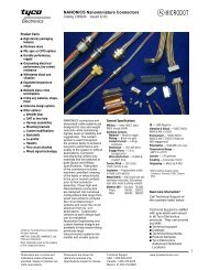
MTA-50 IDC Connectors and Headers
MTA-50 IDC Connectors and Headers
MTA-50 IDC Connectors and Headers

You also want an ePaper? Increase the reach of your titles
YUMPU automatically turns print PDFs into web optimized ePapers that Google loves.
2<br />
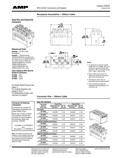
Feed-Thru <strong>and</strong> Closed End<br />
<strong>Connectors</strong><br />
Material <strong>and</strong> Finish<br />
Housing — UL 94V-2 rated,<br />
thermoplastic<br />
Contacts — Phosphor bronze;<br />
.000100 [0.00254] min. tin-lead in wire<br />
termination area, over .0000<strong>50</strong> [0.00127]<br />
min. nickel; choice on mating end:<br />
.000100 [0.00254] min. tin-lead or<br />
.000030 [0.00076] gold or<br />
.000015 [0.00038] gold, over<br />
.0000<strong>50</strong> [0.00127] min. nickel<br />
Color Coding by Wire Size for<br />
UL94V-0 <strong>Connectors</strong><br />
26 AWG — Blue<br />
28 AWG — Green<br />
30 AWG — Brown<br />
For Strain Relief Covers see<br />
page 3.<br />
For mating <strong>Headers</strong> see<br />
pages 6 <strong>and</strong> 7.<br />
For Mateability Guide, see<br />
matrixes on page 8.<br />
Connector Kit Ordering<br />
Information<br />
Connector Kit consists of<br />
Receptacle Assembly <strong>and</strong><br />
Strain Relief Cover.<br />
Base part number prefixes<br />
<strong>and</strong> suffixes indicate the<br />
number of circuit positions,<br />
for example: Base part<br />
number 1445359<br />
2 position = 0-1445359-2<br />
<strong>and</strong><br />
28 position = 2-1445359-8<br />
Note: Tin-plated connectors <strong>and</strong><br />
headers in even position sizes from<br />
2–12 <strong>and</strong> 18 are stocked parts; all<br />
other position sizes <strong>and</strong> products<br />
with gold-plated contacts are<br />
Make To Order.<br />
<strong>MTA</strong>-<strong>50</strong> <strong>IDC</strong> <strong>Connectors</strong> <strong>and</strong> <strong>Headers</strong><br />
Receptacle Assemblies — Ribbon Cable<br />
Connector Kits — Ribbon Cable<br />
Base Part Numbers<br />
Connector Feed-Thru Closed End<br />
Type &<br />
Wire Size<br />
Tin Plated<br />
Connector Kit<br />
Part Nos.<br />
No. of<br />
Circuits<br />
Connector Kit<br />
Part Nos.<br />
No. of<br />
Circuits<br />
26 AWG<br />
0.12-0.15 mm<br />
1445359 2–28 1445368 2–28<br />
2<br />
28 AWG<br />
0.08-0.09 mm<br />
1445362 2–28 1445371 2–28<br />
2<br />
30 AWG<br />
0.05-0.06 mm<br />
1445365 2–28 1445374 2–28<br />
2<br />
.000030 [0.00076] Gold Plated<br />
26 AWG<br />
0.12-0.15 mm<br />
1445361 2–28 1445370 2–28<br />
2<br />
28 AWG<br />
0.08-0.09 mm<br />
1445364 2–28 1445373 2–28<br />
2<br />
30 AWG<br />
0.05-0.06 mm<br />
1445367 2–28 1445376 2–28<br />
2<br />
.000015 [0.00038] Gold Plated<br />
26 AWG<br />
0.12-0.15 mm<br />
1445360 2–28 1445369 2–28<br />
2<br />
28 AWG<br />
0.08-0.09 mm<br />
1445363 2–28 1445372 2–28<br />
2<br />
30 AWG<br />
0.05-0.06 mm<br />
1445366 2–28 1445375 2–28<br />
2<br />
Notes:<br />
Catalog 1309255<br />
Issued 10-02<br />
1. To determine connector overall<br />
length (dim. A), multiply .0<strong>50</strong> x the<br />
number of circuits <strong>and</strong> add .082.<br />
Example: .0<strong>50</strong> x 10 circuits equals<br />
0.<strong>50</strong> + .082 = .582 [14.78].<br />
2. Strain relief covers shown on<br />
page 3 are required <strong>and</strong> sold as<br />
part of the Connector Kit.<br />
3. Str<strong>and</strong>ed UL Style 1061 or<br />
equivalent wire is recommended.<br />
4. Unless otherwise stated all<br />
tolerances (except plating) to be<br />
±.005 [±0.13].<br />
Dimensions are in inches <strong>and</strong> Dimensions are shown for Technical Support www.tycoelectronics.com<br />
millimeters unless otherwise reference purposes only. USA: 1-800-522-6752<br />
specified. Values in brackets Specifications subject to change. Canada: 1-905-475-6222<br />
are metric equivalents. Mexico: 01-800-733-8926