Operating instructions Wireless temperature relay type WR250
Operating instructions Wireless temperature relay type WR250
Operating instructions Wireless temperature relay type WR250

Create successful ePaper yourself
Turn your PDF publications into a flip-book with our unique Google optimized e-Paper software.
MINIPAN ® digital panel meters, <strong>temperature</strong>- and mains controlling,<br />
special purpose instruments for customer requirements www.ziehl.com<br />
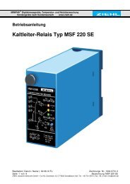
<strong>Operating</strong> <strong>instructions</strong><br />
<strong>Wireless</strong> <strong>temperature</strong> <strong>relay</strong> <strong>type</strong> <strong>WR250</strong><br />
potential-free <strong>temperature</strong> monitoring<br />
Integrated antenna<br />
Input for external antenna when mounted in shielded area (metallic switchgear<br />
cabinet) or under difficult radio reception conditions<br />
ATTENTION: No external antenna included within the scope of supply.<br />
Please order extra when required.<br />
datum / name ) : 13.05.2011 Sc Z. Nr.: 12200-0702-02<br />
Page 1 of 20 Type: <strong>WR250</strong><br />
ZIEHL industrie-elektronik GmbH + Co KG, Daimlerstr.13, D-74523 Schwäbisch Hall, Tel.: +49 791 504-0, Fax: -56, e-mail: info@ziehl.de
Table of Contents<br />
1. Application and brief description ............................................................................ 3<br />
2. Function overview ..................................................................................................... 3<br />
3. Connection diagram ................................................................................................. 3<br />
4. Display and control elements .................................................................................. 4<br />
5. Important information ............................................................................................... 5<br />
6. Installation ................................................................................................................. 6<br />
7. Detailed description .................................................................................................. 6<br />
8. Starting the wireless system .................................................................................... 7<br />
8.1 General notes on operation ................................................................................... 7<br />
8.2 Display mode ........................................................................................................ 7<br />
8.3 Menu mode ........................................................................................................... 7<br />
8.4 Parametrization mode ........................................................................................... 7<br />
8.5 <strong>Operating</strong> flowchart ............................................................................................... 8<br />
8.6 Startup overview.................................................................................................... 9<br />
8.7 Configuration ......................................................................................................... 9<br />
8.8 Registration of wireless sensors ............................................................................ 9<br />
8.9 Alarm parametrization ......................................................................................... 10<br />
8.10 Short-circuit monitoring ....................................................................................... 11<br />
8.11 Relay test ............................................................................................................ 11<br />
8.12 RS485 Modbus interface ..................................................................................... 12<br />
8.13 Sensor Simulation ............................................................................................... 12<br />
8.14 Code lock ............................................................................................................ 13<br />
8.15 Notes on operation: ............................................................................................. 13<br />
8.16 Device reaction time – measuring time tM ........................................................... 14<br />
8.17 Possible values in the display ............................................................................. 14<br />
9. Factory default settings .......................................................................................... 16<br />
10. Servicing and maintenance .................................................................................... 17<br />
11. Troubleshooting ...................................................................................................... 17<br />
11.1 Displaying the software version ........................................................................... 18<br />
12. Technical data ......................................................................................................... 18<br />
13. Design V4 ................................................................................................................ 20<br />
datum / name ) : 13.05.2011 Sc Z. Nr.: 12200-0702-02<br />
Page 2 of 20 Type: <strong>WR250</strong><br />
ZIEHL industrie-elektronik GmbH + Co KG, Daimlerstr.13, D-74523 Schwäbisch Hall, Tel.: +49 791 504-0, Fax: -56, e-mail: info@ziehl.de
1. Application and brief description<br />
The <strong>WR250</strong> wireless <strong>relay</strong> is a receiver and evaluation device for WS Pt 100 wireless<br />
sensors. Up to 6 wireless sensors transmit <strong>temperature</strong> values by radio, which are displayed<br />
and evaluated by the <strong>WR250</strong>.<br />
Use:<br />
for overheating protection in high-voltage transformers (also in primary coils)<br />
for measuring <strong>temperature</strong>s at high potential<br />
where contact-free data transmission by radio is preferred<br />
2. Function overview<br />
evaluation of 1 – 6 WS Pt 100 wireless sensors<br />
measurement and control range 0 … 180°C<br />
4 <strong>relay</strong> output ports (1 changeover contact each), 3 alarms fully programmable<br />
switch points and <strong>relay</strong> function pre-set for transformer control (ventilator, warning and<br />
shut-down)<br />
alarm in case of sensor errors at the «sensor alarm» <strong>relay</strong><br />
multi-voltage power supply AC/DC 24-240 V<br />
display / store the measured MIN and MAX values<br />
interface RS485 (Modbus) for scanning of <strong>temperature</strong> and alarms and for<br />
parametrization<br />
Feeder clamps pluggable<br />
Intergrated antenna, input for external antenna<br />
3. Connection diagram<br />
1) Links for terminating resistor<br />
2) Connector for external antenna<br />
datum / name ) : 13.05.2011 Sc Z. Nr.: 12200-0702-02<br />
Page 3 of 20 Type: <strong>WR250</strong><br />
ZIEHL industrie-elektronik GmbH + Co KG, Daimlerstr.13, D-74523 Schwäbisch Hall, Tel.: +49 791 504-0, Fax: -56, e-mail: info@ziehl.de
4. Display and control elements<br />
1 LEDs <strong>relay</strong> status<br />
K1, K2, K3 lit yellow = <strong>relay</strong> engaged<br />
sensor alarm (K4) lit red = <strong>relay</strong><br />
disengaged<br />
2 Digital display, 4 digits for<br />
<strong>temperature</strong><br />
alarms (8Al1 8, 8Al2 8, 8Al3 8)<br />
error messages (8Err18 … 8Err98)<br />
menu and parameterization mode<br />
3 Key «Up» (in Display mode, normal state)<br />
Press briefly: Change to menu mode (see operating <strong>instructions</strong> item 8.3)<br />
Confirmation for > 2 s: Display MAX values measured by the selected sensor.<br />
Additional pressing of the «Set» key for ≥ 2s will erase the stored MIN/MAX values.<br />
4 Key «Set/Reset» (in Display mode, normal state)<br />
Press briefly: Display the next sensor (sensor LED lit) / display the highest <strong>temperature</strong><br />
measured by all sensors (LEDs for all registered sensors lit)<br />
Confirmation for 10 s: Display the software version (z. B. 80-008)<br />
5 Key «Down» (in Display mode, normal state)<br />
Press briefly: Change to Menu mode (see operating <strong>instructions</strong> item 8.3)<br />
Confirmation for > 2 s: Display the MIN value measured by the selected sensor.<br />
Additional pressing of the «Set» key for ≥ 2s will erase the stored MIN/MAX values.<br />
6 Sensor LEDs<br />
Yellow LEDs on: indicate the wireless sensor currently displayed. If the LEDs for all<br />
registered sensors are lit, the warmest is being shown.<br />
Red LEDs on: indicate an error at the wireless sensor. The sensor can be selected<br />
using key «Set/Reset», and the display will show an Error Code (8Err 8).<br />
The following Error Codes are possible:<br />
8Err18 sensor short-circuited at the WS Pt 100 wireless sensor<br />
8Err28 sensor interruption at the WS Pt 100 wireless sensor<br />
8Err38 no radio contact with the WS Pt 100 wireless sensor<br />
8Err48 illumination of the WS Pt 100 wireless sensor too low<br />
8Err58 energy level of the WS Pt 100 wireless sensor too low<br />
datum / name ) : 13.05.2011 Sc Z. Nr.: 12200-0702-02<br />
Page 4 of 20 Type: <strong>WR250</strong><br />
ZIEHL industrie-elektronik GmbH + Co KG, Daimlerstr.13, D-74523 Schwäbisch Hall, Tel.: +49 791 504-0, Fax: -56, e-mail: info@ziehl.de
5. Important information<br />
WARNUNG<br />
Dangerous electric voltage!<br />
May cause electric shock and burns.<br />
Before beginning work, disconnect system and device.<br />
Correct and safe operations of any device requires that it has been transported and stored<br />
appropriately, installed and commissioned correctly and is being operated according to the<br />
<strong>instructions</strong>.<br />
Only persons familiar with installation, start-up and operations and possessing<br />
qualifications appropriate for their work may perform work on the device. They must<br />
observe the contents of the operating <strong>instructions</strong>, the information printed on the device<br />
and the relevant safety regulations for construction and operation of electric installations.<br />
The devices are manufactured in accordance with DIN / EN and leave the production site<br />
in a condition of safety-related flawlessness.<br />
If in any case the information provided in the operating <strong>instructions</strong> should be insufficient,<br />
please contact us directly, or address your local representative.<br />
When using the device outside the area of applicability of the industrial norms referred to in<br />
the present operating <strong>instructions</strong> and valid in Europe, in their stead comply with the<br />
applicable regulations valid in the country of application.<br />
!<br />
Caution!<br />
Do not connect or disconnect the device under power. Before connecting<br />
the device to the mains, make sure that the control voltage according to the <strong>type</strong><br />
plate (on the side of the device) UC matches the voltage of the grid which the device<br />
is to be connected to!<br />
!<br />
!<br />
Caution!<br />
If the «operating current» function is programmed for all <strong>relay</strong>s, a failure of<br />
control voltage or of the system may remain undetected. When using the device for<br />
control, it is the operator's responsibility to detect this error by regular controls. We<br />
recommend to program at least one <strong>relay</strong> in the system for standby current and to<br />
evaluate it accordingly.<br />
Caution! Multi-voltage power supply<br />
The device is equipped with a multi-voltage power supply suitable for DC and AC power<br />
supply. Before connecting the device to the mains, make sure that the permissible control<br />
voltage range according to the <strong>type</strong> plate (on the side of the device) UC matches the voltage<br />
of the grid which the device is to be connected to!<br />
datum / name ) : 13.05.2011 Sc Z. Nr.: 12200-0702-02<br />
Page 5 of 20 Type: <strong>WR250</strong><br />
ZIEHL industrie-elektronik GmbH + Co KG, Daimlerstr.13, D-74523 Schwäbisch Hall, Tel.: +49 791 504-0, Fax: -56, e-mail: info@ziehl.de
6. Installation<br />
The device can be fastened:<br />
Distributor installation or switching cabinet on 35 mm mounting rail according to EN<br />
60715<br />
Wall-mounting with M4 screws. (additional bar not included in delivery)<br />
Connect in accordance with connection diagram or <strong>type</strong> plate.<br />
Pay attention to the maximally permissible <strong>temperature</strong> when installing into a<br />
switching cabinet. Provide sufficient distance from other devices or heat sources. If<br />
cooling is hampered e. g. by close vicinity of devices with increased surface<br />
<strong>temperature</strong> or by obstruction of the cooling air flow, the permissible ambient<br />
<strong>temperature</strong> is reduced.<br />
7. Detailed description<br />
The <strong>WR250</strong> displays and evaluates the <strong>temperature</strong>s transmitted from the wireless<br />
sensors WS Pt 100.<br />
The hottest wireless sensor switches the <strong>relay</strong>.<br />
For the <strong>relay</strong>s K1 (alarm 1), K2 (alarm 2) and K3 (alarm 3), the following can be<br />
selected individually:<br />
o alarm value<br />
o hysteresis<br />
o response and reset delay<br />
o operation current or standby current<br />
o cyclic <strong>relay</strong> test (e. g. K1 for ventilator)<br />
o alarm in case of error 3 (no radio contact with WS Pt 100)<br />
In case of an error at the WS Pt 100 wireless sensor, the <strong>relay</strong> will switch off the<br />
sensor alarm (K4), and the red LED is lit.<br />
In addition, the MIN and MAX <strong>temperature</strong> values of each WS Pt 100 wireless<br />
sensor are stored.<br />
The device can be polled remotely via a RS485 Modbus interface, and data can be<br />
queried.<br />
Under difficult radio reception conditions or unfavorable mounting positions (e.g. shielded<br />
switchgear-cabinet) an external antenna can be connected.<br />
For more informations concerning ranges and coverage see „APPLICATION NOTE AN001“<br />
at www.enocean.de.<br />
datum / name ) : 13.05.2011 Sc Z. Nr.: 12200-0702-02<br />
Page 6 of 20 Type: <strong>WR250</strong><br />
ZIEHL industrie-elektronik GmbH + Co KG, Daimlerstr.13, D-74523 Schwäbisch Hall, Tel.: +49 791 504-0, Fax: -56, e-mail: info@ziehl.de
8. Starting the wireless system<br />
8.1 General notes on operation<br />
The decimal point behind the last 7-element display shows the operating mode which the<br />
device is in.<br />
8.2 Display mode<br />
Decimal point off (normal state for <strong>temperature</strong> display)<br />
LED yellow<br />
K 1, K 2 and K 3<br />
LED red<br />
sensor alarm<br />
LED Sensor<br />
WS Pt 100<br />
function key<br />
«Set/Reset»<br />
function keys<br />
«Up» and «Down»<br />
8.3 Menu mode<br />
Decimal point on<br />
function keys<br />
«Up» and «Down»<br />
function keys<br />
«Set/Reset»<br />
8.4 Parametrization mode<br />
Decimal point flashing<br />
function key<br />
«Up» and «Down»<br />
function keys<br />
«Set/Reset»<br />
Display current sensor <strong>temperature</strong> in °C (sensor LED lit)<br />
Display the highest <strong>temperature</strong> measured by all attached sensors<br />
(LEDs for all active sensors lit)<br />
Display errors at the wireless sensor with error code (only when<br />
displaying individual sensors), e. g. 8Err18, 8Err28, …<br />
Display alarm messages (8Al1 8, 8al2 8 or 8al3 8)<br />
AN («on») = <strong>relay</strong> engaged<br />
AUS («off») = <strong>relay</strong> disengaged<br />
AN («on») = <strong>relay</strong> disengaged<br />
AUS («off») = <strong>relay</strong> engaged<br />
yellow = <strong>temperature</strong> of the selected wireless sensor is being<br />
displayed. If the LEDs for all registered sensors are lit, the hottest<br />
is being shown.<br />
red = error in selected wireless sensor<br />
Press briefly: Display the next sensor (sensor LED lit) and display<br />
the highest <strong>temperature</strong> measured by all sensors (LEDs for all<br />
registered sensors lit)<br />
Confirmation for 10 s: Display the software version<br />
Press briefly: Change to Menu mode<br />
Confirmation for ≥2 s: Display MIN and MAX values measured by<br />
the selected sensor. Additional pressing of the «Set» key for ≥ 2s<br />
will erase the stored values.<br />
Select the menu items for changing parameters<br />
Press briefly: Select menu item; change to Display mode<br />
Press briefly: Change to Parametrization mode<br />
Press briefly/for a longer time: Change parameter value<br />
(slow/fast)<br />
Press briefly: Accept setting and selection of the next parameter,<br />
after the last parameter change to Menu mode<br />
Note: Press the «Set» key for 2 s to return to Display mode from Menu mode /<br />
Parametrization mode. The same thing happens if no key has been pressed for 30 s<br />
(Exception: 15 min in Simulation mode).<br />
datum / name ) : 13.05.2011 Sc Z. Nr.: 12200-0702-02<br />
Page 7 of 20 Type: <strong>WR250</strong><br />
ZIEHL industrie-elektronik GmbH + Co KG, Daimlerstr.13, D-74523 Schwäbisch Hall, Tel.: +49 791 504-0, Fax: -56, e-mail: info@ziehl.de
Menu mode<br />
8.5 <strong>Operating</strong> flowchart<br />
Display mode<br />
normal state<br />
Parametrization<br />
mode<br />
Sensor LEDs at the <strong>type</strong> plate indicate<br />
the corresponding input ports.<br />
«Up»/«Down» pressed simultaneously<br />
sets values to Zero.<br />
Code reset = 2 s «Set» upon mains<br />
power on (Pin = 504)<br />
Error messages:<br />
Err1 = short circuit in sensor<br />
Err2 = sensor interrupted<br />
Err3 = no radio contact<br />
Err4 = sensor illumination too low<br />
Err5 = sensor energy too low<br />
Err8 = internal error<br />
Err9 = parameter error<br />
datum / name ) : 13.05.2011 Sc Z. Nr.: 12200-0702-02<br />
Page 8 of 20 Type: <strong>WR250</strong><br />
ZIEHL industrie-elektronik GmbH + Co KG, Daimlerstr.13, D-74523 Schwäbisch Hall, Tel.: +49 791 504-0, Fax: -56, e-mail: info@ziehl.de
8.6 Startup overview<br />
required optional Overview<br />
X 8.7 configuration (basic settings of the device)<br />
X 8.8 registration of wireless sensors WS Pt 100<br />
X 8.9 alarm parametrization<br />
X 8.10 <strong>relay</strong> test<br />
X 8.11 sensor simulation<br />
X 8.12 RS485 Modbus interface<br />
X 8.13 code lock<br />
8.7 Configuration<br />
The appropriate program must be selected in accordance with the settings of the wireless<br />
sensors (see operating <strong>instructions</strong> for WS Pt 100 wireless sensors). This is done once<br />
during commissioning.<br />
switch of control voltage at the <strong>WR250</strong><br />
keep «Set» key pressed and switch on control voltage again<br />
after 10 s, 8Pr 5 8 is shown in the display<br />
release «Set» key<br />
select program in accordance with the wireless sensors, using the «Up»/«Down» keys<br />
(program # see operating <strong>instructions</strong> for WS Pt 100 wireless sensor)<br />
press «Set» key<br />
device goes through reset and starts<br />
8.8 Registration of wireless sensors<br />
Start in Display mode (return to Display mode by pressing «Set» key for ≥ 2s). After 30 s<br />
without input, the device will also return to Display mode.<br />
press «Down» key<br />
display 8S 1 .8 / 8off .8 (sensor 1 / off) flashes alternatingly<br />
press «Set» key<br />
press «Down» key («Up» key turns off the sensor input port)<br />
display 8on .8 (on)<br />
press «Set» key<br />
display 8adr .8 / 8lrn .8 (address / learn) flashes alternatingly<br />
within 30 s, briefly (approx. 1 s) link contacts 3 and 4 of the sensor plug-in<br />
socket at the WS Pt 100 wireless sensor (small wire jumper, or if the sensor<br />
plug is plugged in, briefly link the two contacts 3 and 4)<br />
registration OK: Display 8lrnd.8 (learned) will flash 4×<br />
registration error: Display 8Err .8 (error) will flash 4×<br />
display 8S 2 .8 / 8off .8 (sensor 2 / off) flashes alternatingly<br />
register sensors 2 to 6 (optional)<br />
after sensor 6, change to next menu item (parametrization of alarms)<br />
datum / name ) : 13.05.2011 Sc Z. Nr.: 12200-0702-02<br />
Page 9 of 20 Type: <strong>WR250</strong><br />
ZIEHL industrie-elektronik GmbH + Co KG, Daimlerstr.13, D-74523 Schwäbisch Hall, Tel.: +49 791 504-0, Fax: -56, e-mail: info@ziehl.de
8.9 Alarm parametrization<br />
The following parameters are important:<br />
alarm value<br />
8AL 1.8<br />
8AL 2.8<br />
8AL 3.8<br />
hysteresis 8H .8<br />
alarm delay<br />
on<br />
alarm delay<br />
off<br />
limit values for the alarms.<br />
alarm 1 for <strong>relay</strong> K1, alarm 2 for <strong>relay</strong> K2 and alarm 3 for<br />
<strong>relay</strong> K3.<br />
reset value calculated from alarm value + hysteresis<br />
e. g.: 90°C (limit value) + (-5)°C (hysteresis) = 85°C (reset<br />
value)<br />
8dal .8 alarm will be suppressed for the selected time (seconds)<br />
8dof .8<br />
<strong>relay</strong> 8rel .8<br />
Sensor-<br />
Error<br />
alarm will be switched off only after falling below limit (alarm<br />
value + hysteresis) and elapse of this time (seconds)<br />
standby current 8 r.8: In OK state (= alarm value not<br />
reached), the <strong>relay</strong> is engaged, it will be disengaged when<br />
reaching the alarm value.<br />
Advantage: errors and failures generally result in alarm<br />
Disadvantage: alarm also when control voltage is switched<br />
off. Unfavourable e. g. in transformers, in particular if <strong>WR250</strong><br />
control voltage is provided by the transformer to be controlled<br />
operating current 8 a.8: In OK state, the <strong>relay</strong> is<br />
disengaged, it will by engaged upon reaching the alarm<br />
value. No alarm in case of switched-off control voltage and<br />
failures.<br />
8SErr.8 8on .8 alarm if there is no radio contact with the WS Pt 100<br />
wireless sensor (8Err38).<br />
8off .8 no alarm in case of 8Err38<br />
Selection:<br />
use the «Up» and «Down» keys to select menu item until …<br />
display 8AL 1.8 / 8 90.8 (alarm 1 / limit value) flashes alternatingly<br />
press «Set» key<br />
display 8 90.8 (current limit value, value may deviate)<br />
use the «Up» and «Down» keys to select the desired limit value<br />
press «Set» key<br />
display 8H .8 / 8 -5.8 (hysteresis / value) flashes alternatingly<br />
use the «Up» and «Down» keys to select the desired hysteresis<br />
press «Set» key<br />
display 8dal .8 / 8 0.8 (delay alarm / value) flashes alternatingly<br />
use the «Up» and «Down» keys to select the desired value<br />
press «Set» key<br />
display 8dof .8 / 8 0.8 (delay alarm off / value) flashes alternatingly<br />
use the «Up» and «Down» keys to select the desired value<br />
press «Set» key<br />
display 8rel .8 / 8 r.8 (<strong>relay</strong> / Parameter) flashes alternatingly<br />
use the «Up» and «Down» keys to select the desired value<br />
press «Set» key<br />
datum / name ) : 13.05.2011 Sc Z. Nr.: 12200-0702-02<br />
Page 10 of 20 Type: <strong>WR250</strong><br />
ZIEHL industrie-elektronik GmbH + Co KG, Daimlerstr.13, D-74523 Schwäbisch Hall, Tel.: +49 791 504-0, Fax: -56, e-mail: info@ziehl.de
display 8SERR.8 / 8off .8 (sensor error / value) flashes alternatingly<br />
use the «Up» and «Down» keys to select the desired value<br />
press «Set» key<br />
display 8AL 2.8 / 8 100.8 (alarm 2 / limit value) flashes alternatingly<br />
parametrization of alarm 2 and alarm 3<br />
after parametrization of alarm 3, change to next menu item (RS485 Modbus)<br />
8.10 Short-circuit monitoring<br />
To avoid sensor-alarms at sensor-<strong>temperature</strong>s
use the «Up» and «Down» keys to select the duration of the <strong>relay</strong> test,<br />
8 1.8 – 8 999.8 s<br />
press «Set» key<br />
The elapsed test time 8don 8 is stored persistently in the device.<br />
8.12 RS485 Modbus interface<br />
The following parameters are important:<br />
Modbus 8mbus.8 Modbus menu<br />
Address 8Adr .8 Address of device, selectable from range 1 to 247<br />
baud rate 8baud.8 baud rate, 9600 or 19200<br />
parity 8pari.8 parity : 8even.8, 8odd .8, 8no .8 (even, odd, none)<br />
Selection:<br />
select menu item with «Up»/«Down» keys until …<br />
display 8Mbus.8<br />
press «Set» key<br />
display 8Adr .8 / 8 1.8 (address / value) flashes alternatingly<br />
use the «Up» and «Down» keys to select the desired address<br />
press «Set» key<br />
display 8baud.8 / 8 9.6.8 (baud rate / value) flashes alternatingly<br />
use the «Up» and «Down» keys to select the desired baud rate<br />
press «Set» key<br />
display 8pari.8 / 8even.8 (parity / value) flashes alternatingly<br />
use the «Up» and «Down» keys to select the desired value<br />
press «Set» key<br />
leave menu item RS485 Modbus<br />
change to next menu item (Sensor Simulation)<br />
Further informations relating to Modbus configuration and programming can be found in<br />
Appendix 1 (available for download from www.ziehl.de).<br />
8.13 Sensor Simulation<br />
Here you can simulate a <strong>temperature</strong>. All functions of the device will work as if this<br />
<strong>temperature</strong> were actually measured.<br />
If no key has been pressed for 15 minutes, the device automatically returns to Display<br />
mode.<br />
Select menu item with keys «Up»/«Down» until …<br />
display 8Si .8<br />
press «Set» key<br />
use the «Up» and «Down» keys to select the desired <strong>temperature</strong><br />
press «Set» key<br />
leave menu item Simulation<br />
change to next menu item (Code lock)<br />
datum / name ) : 13.05.2011 Sc Z. Nr.: 12200-0702-02<br />
Page 12 of 20 Type: <strong>WR250</strong><br />
ZIEHL industrie-elektronik GmbH + Co KG, Daimlerstr.13, D-74523 Schwäbisch Hall, Tel.: +49 791 504-0, Fax: -56, e-mail: info@ziehl.de
8.14 Code lock<br />
Here you can protect the entered parameters by activating code lock.<br />
The device will reject faulty input with 8Err 8 (flashes 3×).<br />
Select menu item with keys «Up»/«Down» until …<br />
display 8Cod .8 / 8off .8 (Code lock / off or on) flashes alternatingly<br />
press «Set» key<br />
display 8Pin .8 / 8 0.8 (pin / pin code) flashes alternatingly<br />
use the «Up» and «Down» keys to select the stored pin code (factory<br />
default setting is 8 504.8)<br />
press «Set» key<br />
use the «Up» and «Down» keys to select the desired code lock:<br />
o 8off .8 off, any parameter may be modified<br />
o 8EL .8 EasyLimit, only alarm values may be modified<br />
o 8on .8 on, no parameter may be modified<br />
press «Set» key<br />
display 8Pin .8 / 8 504.8 (pin / pin code) flashes alternatingly<br />
use the «Up» and «Down» keys to enter the desired new pin code (Caution:<br />
write down pin code)<br />
press «Set» key<br />
Code lock on, display 8on 8 flashes 3×<br />
Code lock EasyLimit, display 8EL 8 flashes 3×<br />
Code lock off, display 8off 8 flashes 3×<br />
leave menu item Code lock and change to Display mode (normal<br />
state).<br />
8.15 Notes on operation:<br />
After completion of any program item, the program will continue with the next one.<br />
If the right decimal point of the 7-segment display is lit, you have left the Display mode<br />
and may select the individual menu items by pressing «Up»/«Down» (Menu mode).<br />
If the right decimal point flashes, you are in Parametrization mode and may change the<br />
settings by pressing «Up»/«Down».<br />
Pressing «Up»/«Down» for longer periods of time accelerates changes in the display.<br />
Pressing «Up»/«Down» simultaneously sets the selected values to zero.<br />
Reset (pressing «Set/Reset» for 2 s) will take you back to Display mode from any<br />
position in Parametrization mode or Menu mode (exception: Simulation), accepting the<br />
most recently entered value.<br />
datum / name ) : 13.05.2011 Sc Z. Nr.: 12200-0702-02<br />
Page 13 of 20 Type: <strong>WR250</strong><br />
ZIEHL industrie-elektronik GmbH + Co KG, Daimlerstr.13, D-74523 Schwäbisch Hall, Tel.: +49 791 504-0, Fax: -56, e-mail: info@ziehl.de
8.16 Device reaction time – measuring time tM<br />
The reaction time of the device depends on the measuring and transmission times of the<br />
wireless sensors (see operating <strong>instructions</strong> WS Pt 100 wireless sensor).<br />
The wireless sensors measure the <strong>temperature</strong> every 1 s, 10 s or 100 s and transmit it to<br />
the <strong>WR250</strong> after every single, after every 10 th or after every 100 th measurement.<br />
Consequently, there may be delays in sending and evaluating <strong>temperature</strong> changes.<br />
Temperature changes > 4 °C will be sent immediately after measurement.<br />
The delay times 8dal .8 and 8dof .8 may be increased by the duration of the transmission<br />
intervals (± 20%).<br />
8.17 Possible values in the display<br />
In Display mode (normal state)<br />
8al1 8/8al2 8/8al3 8<br />
alarm 1, alarm 2, alarm 3 active (<strong>relay</strong> function dependent on<br />
programming for standby or operating current)<br />
8Err18 sensor short-circuited at the WS Pt 100 wireless sensor<br />
8Err28 sensor interruption at the WS Pt 100 wireless sensor<br />
8Err38 no radio contact with the WS Pt 100 wireless sensor<br />
8Err48 illumination of the WS Pt 100 wireless sensor too low<br />
8Err58 energy level of the WS Pt 100 wireless sensor too low<br />
8Err88 <strong>WR250</strong> internal error<br />
8Err98 parameter error (illogic configuration of the <strong>WR250</strong>)<br />
sensors, Menu mode / Parametrization mode<br />
8S 1 8 … 8S 2 8 sensors 1 to 6<br />
8on 8 / 8off 8 sensors on / off<br />
8Adr 8 / 8Lrn 8 flashes alternatingly, ready for registration of a new sensor<br />
8Lrnd8 new sensor registered successfully (learned)<br />
alarm values, Menu mode / Parametrization mode<br />
8al 18/8al 28/8al 38 alarm values<br />
8H 8 hysteresis<br />
8dal 8 delay until alarm<br />
8dof 8 delay until alarm reset<br />
8rel 8 <strong>relay</strong> function<br />
8 r8 / 8 a8 <strong>relay</strong> function – standby current, operating current<br />
Short-circuit monitoring, Menu mode / Parametrization mode<br />
8SESC8 Short-circuit monitoring<br />
8off 8 / 8on 8 off (without) / on (with) Short-circuit monitoring<br />
datum / name ) : 13.05.2011 Sc Z. Nr.: 12200-0702-02<br />
Page 14 of 20 Type: <strong>WR250</strong><br />
ZIEHL industrie-elektronik GmbH + Co KG, Daimlerstr.13, D-74523 Schwäbisch Hall, Tel.: +49 791 504-0, Fax: -56, e-mail: info@ziehl.de
elay test, Menu mode / Parametrization mode<br />
8tst 8 <strong>relay</strong> test<br />
8AL 8 / 8E 8 alarm / exit<br />
8al 18/8al 28/8al 38 <strong>relay</strong> test on alarm 1 (K1) / alarm 2 (K2) / alarm 3 (K3)<br />
8don 8<br />
shows after which time (in h) the <strong>relay</strong> test will be started or<br />
repeated, respectively<br />
8dof 8 shows how long (in s) the <strong>relay</strong> test has been running<br />
RS485 interface Modbus, Menu mode / Parametrization mode<br />
8Mbus8 Modbus (RS485 interface)<br />
8adr 8 Modbus – device address<br />
8baud8 Modbus – baud rate<br />
8 9.68 / 8 19.28 Modbus – baud rate, 9600 or 19200<br />
8pari8 Modbus – parity<br />
8even8 / 8odd 8 / 8no 8 Modbus – parity bit – even / odd / none<br />
Simulation, Menu mode / Parametrization mode<br />
8Si 8 Simulation<br />
Code lock, Menu mode / Parametrization mode<br />
8Cod 8 Code lock<br />
8Pin 8 pin code<br />
8on 8 / 8el 8 / 8off 8 Code lock on / EasyLimit / off<br />
datum / name ) : 13.05.2011 Sc Z. Nr.: 12200-0702-02<br />
Page 15 of 20 Type: <strong>WR250</strong><br />
ZIEHL industrie-elektronik GmbH + Co KG, Daimlerstr.13, D-74523 Schwäbisch Hall, Tel.: +49 791 504-0, Fax: -56, e-mail: info@ziehl.de
9. Factory default settings<br />
When switching the program (operating <strong>instructions</strong> item «Configuration»), all parameters<br />
are reset to their factory default settings.<br />
Menu<br />
mode<br />
Parameter<br />
Factory default<br />
settings<br />
My data<br />
8S 1 8 8off 8<br />
sensor<br />
1 .. 6<br />
alarm 1<br />
<strong>relay</strong> K1<br />
alarm 2<br />
<strong>relay</strong> K2<br />
alarm 3<br />
<strong>relay</strong> K3<br />
8S 2 8 8off 8<br />
8S 3 8 8off 8<br />
8S 4 8 8off 8<br />
8S 5 8 8off 8<br />
8S 6 8 8off 8<br />
8AL 18 limit 8 908 °C<br />
8H 8 hysteresis 8 -108 °C<br />
8dal 8 delay – alarm 8 08 s<br />
8dof 8 delay – alarm off 8 9998 s<br />
8rel 8 <strong>relay</strong> function 8 a8<br />
8SErr8 alarm sensor error 3 8on 8<br />
8AL 28 limit 8 1308 °C<br />
8H 8 hysteresis 8 -58 °C<br />
8dal 8 delay – alarm 8 08 s<br />
8dof 8 delay – alarm off 8 08 s<br />
8rel 8 <strong>relay</strong> function 8 r8<br />
8SErr8 alarm sensor error3 8off 8<br />
8AL 38 limit 8 1508 °C<br />
8H 8 hysteresis 8 -58 °C<br />
8dal 8 delay – alarm 8 08 s<br />
8dof 8 delay – alarm off 8 08 s<br />
8rel 8 <strong>relay</strong> function 8 a8<br />
8SErr8 alarm sensor error3 8off 8<br />
SESC 8SESC8 Short-circuit monitoring 8on 8<br />
<strong>relay</strong><br />
test<br />
tst<br />
Modbus<br />
Cod<br />
8AL 18<br />
8AL 28<br />
8AL 38<br />
8don 8 Time of test 8off 8<br />
8dof 8 duration of test 8 18<br />
8don 8 Time of test 8off 8<br />
8dof 8 duration of test 8 18<br />
8don 8 Time of test 8off 8<br />
8dof 8 duration of test 8 18<br />
8adr 8 8 18<br />
8baud8 8 9.68<br />
8Pari8 8even8<br />
8on 8 / 8el 8 / 8off 8 8off 8<br />
8Pin 8 8 5048<br />
datum / name ) : 13.05.2011 Sc Z. Nr.: 12200-0702-02<br />
Page 16 of 20 Type: <strong>WR250</strong><br />
ZIEHL industrie-elektronik GmbH + Co KG, Daimlerstr.13, D-74523 Schwäbisch Hall, Tel.: +49 791 504-0, Fax: -56, e-mail: info@ziehl.de
10. Servicing and maintenance<br />
ZIEHL industrie-elektronik GmbH + Co KG<br />
Daimlerstr.13<br />
D-74523 Schwäbisch Hall<br />
Germany<br />
Phone: +49 791 504-0<br />
Fax: +49 791 504-56<br />
Email: info@ziehl.de<br />
Homepage: http://www.ziehl.de<br />
11. Troubleshooting<br />
8Err18 or 8Err28 shown in the display<br />
cause sensor short-circuited or sensor interrupted at the WS Pt 100 wireless sensor<br />
remedy<br />
please check <strong>temperature</strong> sensor at the WS Pt 100 wireless sensor for being<br />
electrically in order and correctly connected.<br />
(see operating <strong>instructions</strong>: WS Pt 100 wireless sensor)<br />
8Err38 shown in the display<br />
no radio contact with the WS Pt 100 wireless sensor<br />
cause<br />
distance from WS Pt 100 wireless sensor too great<br />
storage capacitor in the WS Pt 100 wireless sensor exhaustively<br />
discharged<br />
reduce distance between devices<br />
remedy charge storage capacitor, illuminate WS Pt 100 wireless sensor with > 1000<br />
lux for approx. 2 – 3 hours<br />
8Err48 shown in the display<br />
cause illumination of the WS Pt 100 wireless sensor too low or failed<br />
remedy provide illumination or increase light intensity, respectively<br />
8Err58 shown in the display<br />
cause energy level of the WS Pt 100 wireless sensor too low<br />
remedy<br />
charge storage capacitor, illuminate WS Pt 100 wireless sensor with > 1000 lux<br />
for approx. 2 – 3 hours<br />
8Err88 shown in the display<br />
cause <strong>WR250</strong> internal error<br />
remedy send the device in for examination<br />
8Err98 shown in the display<br />
cause Parameter error (implausible configuration of <strong>WR250</strong>)<br />
remedy check alarm parametrization<br />
datum / name ) : 13.05.2011 Sc Z. Nr.: 12200-0702-02<br />
Page 17 of 20 Type: <strong>WR250</strong><br />
ZIEHL industrie-elektronik GmbH + Co KG, Daimlerstr.13, D-74523 Schwäbisch Hall, Tel.: +49 791 504-0, Fax: -56, e-mail: info@ziehl.de
Device refuses programming<br />
cause Code lock<br />
remedy<br />
The code lock provides protection from unauthorized manipulations of the<br />
device. When code lock is activated, parameters cannot be changed. The pin<br />
can be selected by the user.<br />
pin code unknown? → perform code reset:<br />
Upon activation of the control voltage, keep «Set» key pressed for 2 s<br />
display changes to 888888 – 8Cod 8 – 8off 8 – 888888<br />
release «Set» key<br />
code lock is deactivated, pin code is «504»<br />
No registration of a WS Pt 100 wireless sensor with the <strong>WR250</strong> possible<br />
distance between wireless sensor and <strong>WR250</strong> too great<br />
cause<br />
<br />
<br />
wireless sensor power too low for work<br />
wrong registration contacts linked at the wireless sensor or static linkage of<br />
the contact<br />
reduce distance between the devices<br />
charge storage capacitor, illuminate WS Pt 100 wireless sensor with > 1000<br />
remedy lux for approx. 2 – 3 hours<br />
link registration contacts at the wireless sensor only briefly (see operating<br />
<strong>instructions</strong>: WS Pt 100 wireless sensor)<br />
11.1 Displaying the software version<br />
In Display mode, press the «Set» key for 10 s<br />
12. Technical data<br />
control voltage UC<br />
AC/DC 24 – 240 V 0/50/60 Hz
elay output port 4 × 1 changeover contact<br />
switching voltage max. AC 415 V<br />
switching current max. 5 A<br />
switching capacity<br />
Nominal operation current IE:<br />
max. 1250 VA (ohmic load)<br />
max. 120 W at DC 24 V<br />
AC15 Ie = 3 A Ue = AC 250 V<br />
DC13<br />
Ie = 2 A Ue = DC 24 V<br />
Ie = 0,2 A Ue = DC 125 V<br />
Ie = 0,1 A Ue = DC 250 V<br />
Recommended backup fuse T 3.15 A (gL)<br />
service life of contacts mech. 3 x 10 7 switching cycles<br />
service life of contacts electr. 1 x 10 5 switching cycles at AC 250 V / 6 A<br />
Test conditions EN 50178 / EN 60 947<br />
rated impulse withstand voltage 4000 V<br />
degree of soiling 3<br />
rated insulation voltage UI<br />
300 V<br />
Uptime 100 %<br />
permissible ambient <strong>temperature</strong> -20 °C … +60 °C<br />
EN 60068-2-2 dry heat<br />
EMC – stability EN 61000-6-2<br />
EMC – interference emissions EN 61000-6-3<br />
vibration resistance EN 60068-2-6 2 … 25 Hz ±1,6 mm<br />
25 … 150 Hz 5 g<br />
Casing V4 design, distributor installation<br />
installation depth 55 mm<br />
width 4 TE<br />
dimensions (B × H × T) 70 × 90 × 58 mm<br />
line connector, single wire 1 × 1.5 mm² each<br />
finely stranded with wire end ferrule 1 × 1.0 mm² each<br />
Protection class, casing IP 30<br />
Protection class, clamps IP 20<br />
fastening<br />
snap mounting on bearing rail 35 mm according<br />
to EN 60 715 or screw fastening M 4 (additional<br />
bar not included in delivery)<br />
weight approx. 190 g<br />
Subject to technical modifications<br />
datum / name ) : 13.05.2011 Sc Z. Nr.: 12200-0702-02<br />
Page 19 of 20 Type: <strong>WR250</strong><br />
ZIEHL industrie-elektronik GmbH + Co KG, Daimlerstr.13, D-74523 Schwäbisch Hall, Tel.: +49 791 504-0, Fax: -56, e-mail: info@ziehl.de
13. Design V4<br />
Dimensions in mm<br />
61,8<br />
45<br />
58<br />
48<br />
16,5<br />
1 2 3<br />
3<br />
(90)<br />
4<br />
Option<br />
1 Oberteil / cover<br />
2 Unterteil / base<br />
3 Riegel / bar for snap mounting<br />
4 Plombenlasche / latch for sealing<br />
5 Frontplatteneinsatz / front panel<br />
6 Kennzeichen für unten / position downward<br />
7 Riegel bei Wandbefestigung mit Schrauben. Riegelbohrung Ø 4,2 mm / for fixing<br />
to wall with screws, Ø 4,2 mm<br />
Sie finden diese und weitere Betriebsanleitungen, soweit verfügbar auch in englisch, auf<br />
unserer Homepage www.ziehl.de.<br />
You find this and other operating-manuals on our homepage www.ziehl.de, as far as<br />
available also in English.<br />
datum / name ) : 13.05.2011 Sc Z. Nr.: 12200-0702-02<br />
Page 20 of 20 Type: <strong>WR250</strong><br />
ZIEHL industrie-elektronik GmbH + Co KG, Daimlerstr.13, D-74523 Schwäbisch Hall, Tel.: +49 791 504-0, Fax: -56, e-mail: info@ziehl.de<br />
5<br />
116<br />
98<br />
6<br />
70<br />
7