Digidim 458/DIM8 8-Channel Dimmer Module - Helvar
Digidim 458/DIM8 8-Channel Dimmer Module - Helvar
Digidim 458/DIM8 8-Channel Dimmer Module - Helvar

Create successful ePaper yourself
Turn your PDF publications into a flip-book with our unique Google optimized e-Paper software.
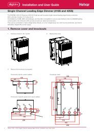
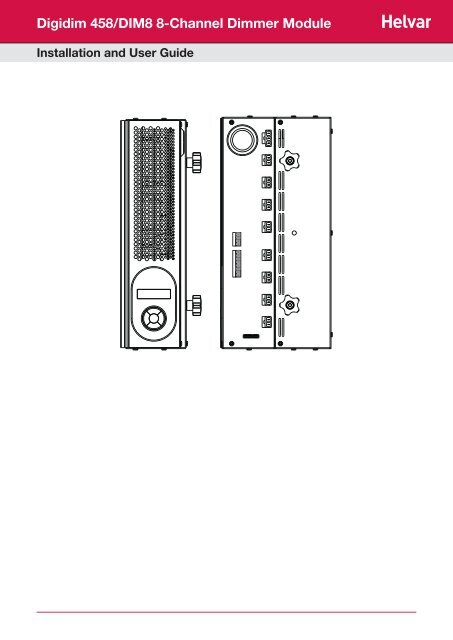
<strong>Digidim</strong> <strong>458</strong>/<strong>DIM8</strong> 8-<strong>Channel</strong> <strong>Dimmer</strong> <strong>Module</strong><br />
Installation and User Guide
Introduction<br />
The <strong>458</strong>/<strong>DIM8</strong> is an 8-channel digital thyristor dimmer module, for leading-edge dimming of resistive and inductive loads.<br />
It has both a DALI and an S-DIM/DMX interface, and so can be fully integrated into a <strong>Digidim</strong> or Imagine router system.<br />
It can also be controlled by the <strong>Helvar</strong> TouchPanel, or used on standalone DALI or <strong>Digidim</strong> systems.<br />
NOTE: DALI AND S-DIM / DMX MUST NOT BE CONNECTED SIMULTANEOUSLY.<br />
Chassis modules<br />
The <strong>458</strong>/<strong>DIM8</strong> module is attached to the <strong>458</strong>M1, <strong>458</strong>M2 or <strong>458</strong>M3 chassis. The chassis modules are supplied with control<br />
module by-pass connectors, and can be fully installed and wired prior to fitting of the control module(s). This allows for all<br />
electrical installation, testing and powering up of the lighting circuits to be carried out prior to the fitting of the control modules.<br />
This prevents possible damage to the control modules due to circuit overload or faults, or the use of high voltage insulation<br />
testing equipment.<br />
LCD display and keypad<br />
The front of the module is equipped with an LCD display and keypad to set basic configuration parameters and provide basic<br />
control of channel and output levels.<br />
<strong>Channel</strong>s and load protection<br />
The <strong>458</strong>/<strong>DIM8</strong> module has 8 channels rated at 10 A, with a total current capacity of 48 A, which can be configured as 8 x 6 A<br />
channels or 4x10 A channels.<br />
Note: the correct chassis load protection must be chosen to ensure the required channel ratings are achieved, but not exceeded.<br />
The dimmer module provides an auxiliary power supply, which can be used to power one TouchPanel, and has an optional<br />
<strong>Digidim</strong> power supply, which can be used to power DALI systems, if required.<br />
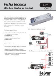
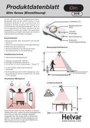
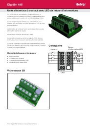
Load<br />
connection<br />
sockets<br />
DALI<br />
connections<br />
Terminal<br />
block<br />
provided<br />
Override,<br />
TouchPanel,<br />
S-DIM/DMX<br />
connections*<br />
Terminal<br />
block<br />
provided<br />
with<br />
<strong>458</strong>Mx<br />
Chassis<br />
<strong>Dimmer</strong> mains<br />
supply connector<br />
Options module<br />
connection socket<br />
Attachment<br />
knob<br />
2 <strong>Helvar</strong> <strong>Digidim</strong> <strong>458</strong>/<strong>DIM8</strong> 8-<strong>Channel</strong> <strong>Dimmer</strong> <strong>Module</strong>: Installation and User Guide<br />
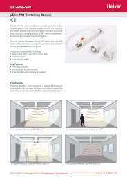
Heat sink<br />
Grille<br />
LCD Display<br />
Keypad<br />
Attachment<br />
knob
Installation<br />
1. Attach the module to a chassis<br />
Mounting, Environmental and Clearance Requirements<br />
Mounting<br />
• Attach the <strong>458</strong>/<strong>DIM8</strong> to a <strong>458</strong>M1, <strong>458</strong>M2, or <strong>458</strong>M3 chassis, which is mounted vertically on a flat surface.<br />
Environment<br />
• The ambient temperature must be between 0ºC and 40ºC.<br />
• Air humidity must be between 0% and 90% (non-condensing).<br />
• The area must be adequately ventilated.<br />
• Do NOT install this product in a damp location.<br />
Clearance<br />
• For effective ventilation, ensure that there is adequate space around the combined chassis and module(s): 50 mm above,<br />
below and on both sides. Refer to the mounting dimensions and clearance diagrams in the <strong>458</strong>Mx Chassis Installation Guide.<br />
• When a <strong>Helvar</strong> control module (e.g. dimmer unit) is attached, the grilles must NOT be obstructed.<br />
Refer to the <strong>Helvar</strong> <strong>458</strong>Mx Chassis Installation Guide for further information.<br />
WARNING:<br />
IMPORTANT:<br />
Refer to the <strong>458</strong>Mx Chassis Installation Guide for details.<br />
Unscrew and remove blanking plate(s) from the chassis.<br />
Note 1: <strong>458</strong>M1: 1 blanking plate;<br />
<strong>458</strong>M2: 2 blanking plates;<br />
<strong>458</strong>M3: 3 blanking plates.<br />
BEFORE ATTACHING THE MODULE AND MAKING ANY CONNECTIONS, ENSURE<br />
THAT THE MAINS SUPPLY IS ISOLATED.<br />
The dimmer may be controlled by either DALI or S-DIM/DMX, but DALI AND S-DIM / DMX<br />
MUST NOT BE CONNECTED SIMULTANEOUSLY.<br />
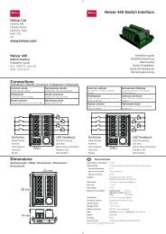
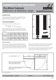
1.1 Remove chassis cover<br />
1.1 Remove chassis blanking plates<br />
Note 2: The diagrams on this page show the <strong>458</strong>M1/4S10 Chassis.<br />
Covers and knockouts are removed from the <strong>458</strong>M2 and <strong>458</strong>M3 in a similar way.<br />
1.2 Loosen attachment knobs<br />
Partially unscrew the two knobs on the dimmer module to reveal the pins.<br />
1.3 Slot module pins into mounting bracket<br />
Attach the module to the chassis by slotting the pins of the module to the<br />
mounting bracket.<br />
1.4 Tighten knobs<br />
Screw the knobs to the mounting bracket to secure the module.<br />
<strong>Helvar</strong> <strong>Digidim</strong> <strong>458</strong>/<strong>DIM8</strong> 8-<strong>Channel</strong> <strong>Dimmer</strong> <strong>Module</strong>: Installation and User Guide<br />
Blanking<br />
plate<br />
Loosen<br />
knobs<br />
3
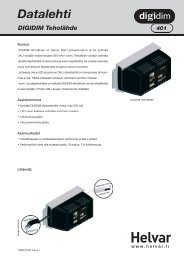
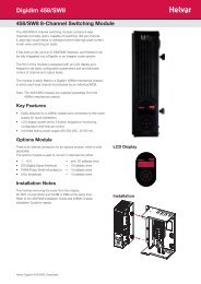
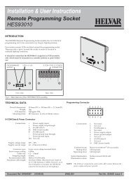
2. Connect power and load cables to module sockets<br />
Connect the mains control supply as shown below.<br />
The dimmer channel cables from the <strong>458</strong>M chassis will be plugged into the chassis bypass terminals.<br />
Unplug the cables from the bypass terminals, and connect them to the dimmer module channel terminals.<br />
Note: The diagram on this page show the <strong>458</strong>M1 chassis. Cable connection is similar for the <strong>458</strong>M2 and <strong>458</strong>M3.<br />
DA-<br />
DA+<br />
Power link<br />
+<br />
1<br />
2<br />
3<br />
4<br />
5<br />
6<br />
7<br />
8<br />
Options module<br />
connection socket<br />
Link for DALI<br />
power<br />
4 <strong>Helvar</strong> <strong>Digidim</strong> <strong>458</strong>/<strong>DIM8</strong> 8-<strong>Channel</strong> <strong>Dimmer</strong> <strong>Module</strong>: Installation and User Guide<br />
Bypass<br />
terminals<br />
S-DIM/DMX<br />
cable<br />
loom<br />
DALI supply connections Touch Panel power, Override, and<br />
S-DIM/DMX connections<br />
Override<br />
Touch Panel<br />
Power<br />
S-DIM/DMX<br />
OVR<br />
0 V<br />
+<br />
A<br />
0 V<br />
SCN<br />
B<br />
TERM<br />
Connect external switch<br />
for override operation<br />
Link for<br />
termination
3. Make control connections<br />
Refer to the connection diagrams on the previous page.<br />
Ensure that all the necessary control connections have been made correctly and securely.<br />
IMPORTANT:<br />
ENSURE SEGREGATION BETWEEN MAINS CABLING AND OTHER CONNECTIONS.<br />
DALI AND 1 – 10 V BALLAST CONNECTIONS SHOULD BE CONSIDERED AS POTENTIALLY LIVE.<br />
3.1 DALI connections<br />
If connecting to a <strong>Digidim</strong> system, use the DA+ and DA- terminals of the DALI connector.<br />
If the built-in 250mA DALI power supply is required, wire between the ‘+’ and ‘Power Link’ terminals of the DALI<br />
connector to provide DALI power.<br />
IMPORTANT: REMEMBER THAT YOU CANNOT EXCEED THE DALI POWER SUPPLY LIMIT OF 250 mA<br />
3.2 Override connections<br />
If you wish to provide output level override functionality, wire a switch between the ‘0 V’ and ‘OVR’ terminals of the<br />
S-DIM or DMX connector. Switch closure sets the light output of all dimmer channels to the override level.<br />
3.3 Touch Panel power connections<br />
Power can be supplied to one TouchPanel from the TouchPanel power connection terminal.<br />
3.4 S-DIM and DMX connections<br />
If connecting to a <strong>Helvar</strong> Imagine system, plug in the connector of the S-DIM/DMX cable loom to the S-DIM/DMX<br />
terminals. This is attached to the DIN-rail inside the chassis.<br />
If the dimmer is at the end of the S-DIM/DMX cable, wire a link between the ‘TERM’ and ‘B’ connections of the<br />
S-DIM/DMX terminals to enable the cable termination.<br />
4. Replace chassis cover<br />
Replace the chassis cover, using the original screws.<br />
5. Power on the unit<br />
Power up the dimmer unit by switching on the MCBs.<br />
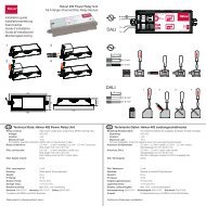
The LCD display should appear as shown.<br />
<strong>Helvar</strong> <strong>Digidim</strong> <strong>458</strong>/<strong>DIM8</strong> 8-<strong>Channel</strong> <strong>Dimmer</strong> <strong>Module</strong>: Installation and User Guide<br />
Start-up screen of module LCD display<br />
5
Load Types<br />
The <strong>458</strong>/<strong>DIM8</strong> is a thyristor dimmer and can control most load types, including:<br />
• incandescent lamps;<br />
• low-voltage halogen lamps with conventional and dimmable electronic transformers;<br />
• mains halogen lamps;<br />
• neon lamps with conventional and dimmable electronic transformers;<br />
• dimmable LED lamps.<br />
The table below shows the compatible load types and the minimum and maximum power per channel.<br />
Note: This table should be used as a guide only. Always refer to the manufacturer’s data for load capacities and dimming<br />
compliancy.<br />
Load Minimum<br />
per channel<br />
Note 1: For other load types, refer to manufacturer’s data.<br />
Note 2: Transformers must be approved for dimming use by the transformer manufacturer.<br />
Note 3: We recommend lamp loading of the transformer to no more than 80% of the nominal transformer power, unless<br />
otherwise specified by the transformer manufacturer. For example, a 500 VA transformer should not be loaded to more<br />
than 400 W of lamp load. In addition, the transformer has to be short-circuit proof on the secondary side, or it must<br />
be equipped with thermal protection on the primary side. The thermal protection is to be non-resettable or manually<br />
resettable only.<br />
6 <strong>Helvar</strong> <strong>Digidim</strong> <strong>458</strong>/<strong>DIM8</strong> 8-<strong>Channel</strong> <strong>Dimmer</strong> <strong>Module</strong>: Installation and User Guide<br />
Maximum<br />
per channel<br />
(see note 3)<br />
Incandescent lamps / 230 V (mains) halogen lamps 25 W 2300 W<br />
Low-voltage tungsten halogen wire-wound transformer<br />
(see notes 1 & 2)<br />
50 VA 2300 VA<br />
Dimmable cold cathode wire-wound transformer 50 VA 2300 VA<br />
Leading-edge electronic transformers for low voltage halogen lamps See notes 1 and 2<br />
Leading-edge electronic transformers for dimmable cold cathode See notes 1 and 2
Control Panel<br />
Control Panel Functions<br />
The control panel is used to view and adjust:<br />
- dimmer channel levels and (if connected) option module output levels<br />
- various dimmer and options module settings<br />
S-DIM connection<br />
Example: to <strong>Helvar</strong> 920 Routers, or to <strong>Helvar</strong> TouchPanel.<br />
Adjust these parameters using the control panel:<br />
<strong>Channel</strong> pairing (if <strong>458</strong>/OPT4 options module connected)<br />
SCR Drive mode<br />
S-DIM addresses<br />
Other parameters can be set using Designer software<br />
DMX connection<br />
Example: to <strong>Helvar</strong> 920 Routers, or to TouchPanel.<br />
Adjust these parameters using the control panel:<br />
<strong>Channel</strong> pairing (if <strong>458</strong>/OPT4 options module connected)<br />
Dimming curve<br />
DMX addresses<br />
Minimum fade time<br />
Output mode<br />
Override level<br />
SCR Drive mode<br />
Switch-on level<br />
Other parameters can be set using Designer software<br />
DALI connection<br />
Example: to <strong>Helvar</strong> 920 Routers.<br />
Adjust these parameters using the control panel:<br />
<strong>Channel</strong> pairing (if <strong>458</strong>/OPT4 options module connected)<br />
Dimming curve<br />
Minimum fade time<br />
Override level<br />
SCR Drive mode<br />
Other parameters can be set using Designer software<br />
DALI standalone connection with Toolbox software<br />
Adjust these parameters using the control panel:<br />
<strong>Channel</strong> pairing (if <strong>458</strong>/OPT4 options module connected)<br />
Dimming curve<br />
Minimum fade time<br />
Output mode<br />
Override level<br />
SCR Drive mode<br />
Other parameters can be set using Toolbox software<br />
<strong>Helvar</strong> <strong>Digidim</strong> <strong>458</strong>/<strong>DIM8</strong> 8-<strong>Channel</strong> <strong>Dimmer</strong> <strong>Module</strong>: Installation and User Guide<br />
Control panel<br />
DALI standalone connection<br />
This allows basic, ‘out of box’ scene recall, modify and store from DALI control panels. Other settings can be changed using the<br />
module control panel.<br />
Note:<br />
If S-DIM or DMX is connected and you change lighting levels or recall scenes on the Control Panel, then, after a short period of<br />
time, the levels revert to those being sent by the S-DIM/DMX master.<br />
7
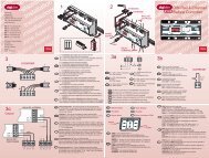
Control panel LCD display<br />
S-DIM / DMX Activity<br />
and DALI Power /<br />
Activity Indicator<br />
<strong>Channel</strong>(s) or<br />
output(s) level %<br />
If the Options module is connected,<br />
output channel levels are displayed<br />
S-DIM / DMX Activity and DALI Power / Activity Indicator:<br />
<strong>Channel</strong> / Output level %<br />
LCD Display Main Screen<br />
Control panel keypad<br />
<strong>Channel</strong> numbers<br />
<strong>Channel</strong><br />
levels<br />
indicators<br />
This indicator in the top left-hand corner of the ‘Display Screen’ indicates S-DIM/DMX activity or DALI power / activity:<br />
For S-DIM / DMX it is normally off, and flashes on intermittently for activity<br />
If DALI power is on, then the indicator is on. It flashes to indicate DALI activity.<br />
The percentage shown is the level of the currently selected channel(s) or output(s).<br />
‘ALL’ is displayed here if all channels or outputs are selected simultaneously, but are set to different levels.<br />
Main screen for 8-channel dimmer<br />
<strong>Helvar</strong> <strong>Digidim</strong> <strong>458</strong>/<strong>DIM8</strong> 8-<strong>Channel</strong> <strong>Dimmer</strong> <strong>Module</strong>: Installation and User Guide<br />
The Main Display Screen appears:<br />
- When the <strong>458</strong>/<strong>DIM8</strong> is powered on<br />
- After 60 seconds of inactivity on the Control Panel.<br />
- After exiting the control panel options<br />
Use the keypad to:<br />
- set dimmer channel levels<br />
- set output channel levels (if an Options <strong>Module</strong> is connected)<br />
- navigate the system menus to adjust module settings<br />
8
Adjusting channel and output levels using the keypad<br />
Follow these steps to adjust channel and output levels<br />
1. (From the LCD Display Main Screen):<br />
Press either RIGHT or LEFT to access the dimmer and output (option)<br />
channel levels.<br />
2. Step left or right through channels / outputs<br />
The selected channel(s) or output(s) are shown by a flashing bar or ‘o’<br />
(to indicate 0% light level).<br />
3. Adjust lighting level percentage (%) for the selected channel(s).<br />
4. Return to Main Display Screen<br />
Changing Lighting Levels for <strong>Dimmer</strong> <strong>Channel</strong>s when <strong>458</strong>/OPT4 connected<br />
<strong>Channel</strong> pairing<br />
If the <strong>458</strong>/OPT4 Options <strong>Module</strong> is connected, by default, dimmer channels 1-4 are paired with outputs (options) 1-4.<br />
When a channel is paired the dimmer channel will operated in switch mode.<br />
Changing the levels of dimmer channels 1-4 affects the levels of outputs 1-4 accordingly.<br />
If a channel is altered to non-paired (separate) operation, it is then possible to set its curve in the ‘Dimming Curves’ sub-menu.<br />
Switch mode<br />
When in switch mode, the dimmer channels will only turn on or off, and they will not dim.<br />
Examples:<br />
In switch mode (for DALI) with a dimmer channel level set to 1%, the channel turns on to 100%, and if set to 0%, it turns off;<br />
In switch mode (for S-DIM/DMX) with a dimmer channel level set to 2% (default switch-on level for S-DIM/DMX), the channel<br />
turns on to 100%, and if set to 1%, it turns off. This setting can be changed in the ‘Dimming Curves’ sub-menu.<br />
<strong>Helvar</strong> <strong>Digidim</strong> <strong>458</strong>/<strong>DIM8</strong> 8-<strong>Channel</strong> <strong>Dimmer</strong> <strong>Module</strong>: Installation and User Guide<br />
9
Navigating the menu using the keypad<br />
Follow these steps to access and navigate the menus<br />
1. (From the LCD Display Main Screen):<br />
Physical selection<br />
Press UP or DOWN to access the menu options.<br />
2. Scroll through main options.<br />
3. Select an option (access option screen).<br />
4.<br />
Adjust parameters.<br />
5. Step between different parameters in options screens<br />
6. Return to previous menu.<br />
Return to Main Display Screen (from main menu)<br />
Physical selection mode allows loads and controls to be grouped together. It can be activated for a piece of equipment in<br />
a number of ways, including by using a <strong>Helvar</strong> remote control unit, or by using Designer or Toolbox software. Refer to the<br />
equipment instructions for details.<br />
Follow these steps to use the module to identify a piece of equipment using physical selection mode.<br />
1. - Put the piece of equipment (e.g. router, sensor etc) into ‘physical<br />
selection mode’ (refer to the manufacturer’s instructions)<br />
2. (From LCD display main page):<br />
Press either RIGHT or LEFT to access the dimmer and output (option)<br />
channel levels.<br />
3. Step left or right through channels to select the channel to be used for<br />
physical selection.<br />
4. Press UP or DOWN to physical select the channel<br />
5. - Repeat steps 3 and 4 for each channel, as necessary.<br />
6. - Once identified, end ‘Physical selection mode’ for the piece(s) of<br />
equipment (refer to the manufacturer’s instructions)<br />
<strong>Helvar</strong> <strong>Digidim</strong> <strong>458</strong>/<strong>DIM8</strong> 8-<strong>Channel</strong> <strong>Dimmer</strong> <strong>Module</strong>: Installation and User Guide<br />
10
<strong>Module</strong> Menu Options<br />
Main Menu<br />
Use the keypad to access and navigate and adjust the menu options: see ‘Navigating the menu using the keypad.’<br />
Below is a table listing the main options available from the module control panel. Full options details are listed in the next section.<br />
Addresses<br />
Ballast output<br />
Unit Details<br />
Recall scene<br />
Save as scene<br />
Default scenes<br />
Groups<br />
Dimming curves<br />
Min fade time<br />
Power on level<br />
Failure level<br />
Override level<br />
Minimum level<br />
<strong>Helvar</strong> <strong>Digidim</strong> <strong>458</strong>/<strong>DIM8</strong> 8-<strong>Channel</strong> <strong>Dimmer</strong> <strong>Module</strong>: Installation and User Guide<br />
Set S-DIM, DMX and DALI addresses, including base addresses, and S-DIM/DMX mode.<br />
View and refresh ballast status; pair dimmer and ballast channels; set output mode.<br />
View module serial number, firmware version, and various other service-related<br />
information.<br />
Recall DALI scenes.<br />
Save levels as a DALI scene.<br />
Reset DALI scenes to default settings.<br />
Group and ungroup dimmer and ballast channels.<br />
Select dimming curves for dimmer channels.<br />
Set minimum fade times for dimmer and ballast channels.<br />
Set DALI power-on levels for dimmer and ballast channels.<br />
Set (or disable) DALI failure levels for dimmer and ballast channels.<br />
Set (or disable) override levels for dimmer and ballast channels.<br />
Set DALI minimum load levels for dimmer and ballast channels.<br />
Switch-on level Set switch-on levels for S-DIM/DMX channels.<br />
Max load level<br />
Hysteresis<br />
SCR drive mode<br />
LCD contrast<br />
LCD timeout<br />
Factory reset<br />
Use password<br />
Enter password<br />
Set maximum load levels for dimmer and ballast channels.<br />
Activate / De-activate S-DIM hysteresis for dimmer and ballast channels.<br />
Select Hybrid, Triac or SCR (thyristor) drive mode.<br />
Adjust the LCD contrast level.<br />
Activate / De-activate the LCD display timeout function.<br />
Reset all settings to factory defaults.<br />
Apply password lock to settings (except to ‘Unit details’ and ‘Enter password’ items).<br />
Remove the password lock (see ‘Use password’)<br />
11
Menu Options Details<br />
Addresses<br />
The digital interface (DALI or S-DIM/DMX) receives control messages from devices in the system.<br />
You can set any address to any channel.<br />
Note: The base address is the first channel address, from which the remaining addresses are allocated (unless changed manually<br />
in the address sub-menu).<br />
Sub-menu items Options<br />
S-DIM/DMX mode DMX or S-DIM (Default)<br />
S-DIM/DMX base S-DIM Base: 1 – 247 (Default: 1)<br />
DMX base: 1 - 505<br />
S-DIM/DMX addr <strong>Channel</strong>: 1 – 8<br />
S-DIM Address: 1 – 254; Disabled (Default: 1)<br />
DMX Address: 1 - 512; Disabled (Default: 1)<br />
DALI base DALI Base: 1 – 57 (Default: 1)<br />
DALI addresses <strong>Channel</strong>: 1 – 8<br />
Address: 1 – 64; Removed; Disabled<br />
Removed: Next time you connect it to a controller program or router, the DALI<br />
address will be re-allocated<br />
Disabled: The address will not be reallocated<br />
Ballast output<br />
Sub-menu items Options<br />
Status (Read-only) ---- = No ballast outputs present<br />
Refresh Rechecks status of ballast outputs<br />
<strong>Channel</strong> pairs Ballast <strong>Channel</strong>: 1 – 4<br />
<strong>Dimmer</strong> <strong>Channel</strong>: 1 – 4; Separate<br />
You can configure these settings only if there is an Options <strong>Module</strong> connected.<br />
Whilst paired with a dimmer channel, the dimmer channel will operate in switch mode.<br />
Output mode <strong>Channel</strong>: 1 – 4;<br />
ALL<br />
(Default: 1)<br />
Mode: 0: 0/10V<br />
1: 1-10V sink<br />
2: 0-10V<br />
3: PWM +<br />
4: PWM –<br />
5: DALI b’cast<br />
6: DSI<br />
7: (Off)<br />
<strong>Helvar</strong> <strong>Digidim</strong> <strong>458</strong>/<strong>DIM8</strong> 8-<strong>Channel</strong> <strong>Dimmer</strong> <strong>Module</strong>: Installation and User Guide<br />
12
Unit Details<br />
Sub-menu items Options<br />
Details (Read-only) Serial number and Firmware version<br />
Mode Mode, power and data information<br />
If DALI power is on, a tick appears next to the DALI power field.<br />
DALI or S-DIM/DMX shows the last detected mode when the module was reset.<br />
Temperatures (Read-only) Heatsink and internal temperatures<br />
Highest (Read-only) Highest logged heatsink and internal temperatures<br />
Mains (Read-only) Mains voltage, frequency and reference voltage<br />
User mode (All read-only); Refer to the ‘Troubleshooting’ section of this guide for message details.<br />
Recall Scene<br />
Recall a scene previously stored (temporarily if connected to a <strong>Helvar</strong> router system).<br />
Scenes are sets of lighting levels and can make use of any combination of channels.<br />
This option is always available, even when password protection is applied to other options.<br />
Range: Scene 1 -16<br />
Save as Scene<br />
The levels which are currently active for all channels of the dimmer are applied to this scene. You can recall stored scenes in the<br />
‘Recall Scene’ menu (see above).<br />
Range: Scene 1 -16<br />
Default scenes<br />
Default lighting scenes can be applied to the dimmer channels, i.e. scene 1 = 100%, scene 2 = 75%, scene 3 = 50%, and<br />
scene 4 = 25%.<br />
Note: Lighting levels are NOT changed automatically once you apply default scenes; but once you recall a scene, lighting is set<br />
to the levels for that scene.<br />
Groups<br />
Assign channels to DALI groups. Any channel can be assigned to any group.<br />
Options:<br />
Group: 1 – 16<br />
<strong>Dimmer</strong> options: (Up button);<br />
x (Down button).<br />
(Default: xxxx)<br />
<strong>Helvar</strong> <strong>Digidim</strong> <strong>458</strong>/<strong>DIM8</strong> 8-<strong>Channel</strong> <strong>Dimmer</strong> <strong>Module</strong>: Installation and User Guide<br />
13
Dimming curves<br />
Configure the shape of the dimming curve to suit the requirements of your lighting equipment.<br />
Options:<br />
<strong>Channel</strong>: 1 – 8; ALL<br />
Curves: 0: Non-dim (Switch mode)<br />
1: Linear (S-DIM mode) (S-DIM default)<br />
2: Square (S-DIM mode curve)<br />
3: S-Law (S-DIM mode curve)<br />
4: Log (DALI mode curve) (DALI default)<br />
5: SSL (DALI mode curve) [SSL = Solid State Lighting]<br />
6: Linear (DALI mode curve)<br />
Min fade time<br />
Set the minimum time it takes to change between minimum and maximum lighting levels.<br />
Options:<br />
<strong>Channel</strong>: 1 – 8, ALL<br />
Fade time: 0: 20 ms<br />
1: 150 ms<br />
2: 500 ms<br />
3: 1 sec (Default)<br />
Power on level<br />
Set the level each channel will go to when the unit is powered on, with DALI connected.<br />
Note: Power-on levels for S-DIM are set in the router, and not using the control panel.<br />
Options:<br />
<strong>Channel</strong>: 1 – 8;<br />
ALL<br />
Power on level: 0 – 100%;<br />
Last<br />
(Default in DALI mode:100%)<br />
Failure level<br />
Set channel levels for situations where the DALI bus goes low, such as when it is short-circuited or the DALI PSU is turned off.<br />
Options:<br />
<strong>Channel</strong>: 1 – 8;<br />
ALL<br />
Failure level: 0 – 100%;<br />
**** (= do not apply Failure level);<br />
(Default:100%)<br />
<strong>Helvar</strong> <strong>Digidim</strong> <strong>458</strong>/<strong>DIM8</strong> 8-<strong>Channel</strong> <strong>Dimmer</strong> <strong>Module</strong>: Installation and User Guide<br />
14
Override level<br />
If the override input connection is short-circuited, e.g. by contact closure on an alarm system, all channels are set to their<br />
override level, regardless of external control signals.<br />
Options:<br />
<strong>Channel</strong>: 1 – 8;<br />
ALL<br />
Override level:<br />
0 – 100%;<br />
**** (= do not apply override level);<br />
(Default:100%)<br />
Minimum level<br />
Set the minimum DALI lighting level the channel will achieve when turned on, no matter what scene is called or level is set.<br />
For example, if you set a minimum level of 50% and call scene 4 (at 25% level), the channel output level will be 50%.<br />
For S-DIM/DMX, the level set here is actually the switch-on level, and the channel will not turn on unless it receives a command<br />
to go to or above this level. See Switch-on level (below).<br />
The minimum level is 1% by default. If you set the minimum level to 100%, this forces the dimming curve into switch mode.<br />
Options:<br />
<strong>Channel</strong>: 1 – 8;<br />
ALL<br />
Minimum level: 0.1%;<br />
1% – 100%;<br />
(Default: 0.1%)<br />
Switch-on level<br />
Set the switch-on levels for S-DIM/DMX channels.<br />
Options:<br />
<strong>Channel</strong>: 1 – 8;<br />
ALL (Default)<br />
Switch-on level: 0% – 64%;<br />
(Default: 2%)<br />
Max load level<br />
Limit the maximum output level of each channel. You can set the maximum level to between 1% and 100%.<br />
Note: The maximum level is 100% by default.<br />
Options:<br />
<strong>Channel</strong>: 1 – 8;<br />
ALL<br />
Maximum level: 1% – 100%;<br />
(Default:100%)<br />
<strong>Helvar</strong> <strong>Digidim</strong> <strong>458</strong>/<strong>DIM8</strong> 8-<strong>Channel</strong> <strong>Dimmer</strong> <strong>Module</strong>: Installation and User Guide<br />
15
Hysteresis<br />
Note: Hysteresis is supported only when controlled by S-DIM.<br />
This setting affects the level at which the channel turns off. When hysteresis is on, the switch-off level is 80% of the switch-on<br />
level. At or below the switch-off level, the channel will be off. For example, if the switch on level is 50%, and the signal rises to this<br />
level or above, the channel turns on, then if the signal falls to 40% or below, the channel turns off.<br />
By default on the dimmer:<br />
- When hysteresis is on and the signal rises to 2%, the lighting for that channel turns on; when it falls to 0%, the channel turns off.<br />
- When hysteresis is off (default setting) and the signal rises to 2%, the lighting for that channel turns on; when it falls to 1%, the<br />
channel turns off.<br />
Options:<br />
<strong>Channel</strong>: 1 – 8;<br />
ALL<br />
Off: (up button);<br />
x (down button)<br />
(Default: x)<br />
SCR Drive Mode<br />
Set the output mode to allow for various load types. This sets the mode for all outputs of the dimmer: they cannot be set<br />
independently.<br />
Options:<br />
SCR drive mode:<br />
LCD Contrast<br />
0 Hybrid (Default);<br />
1 Triac;<br />
2 SCR (thyristor) [SCR: silicon-controlled rectifier]<br />
Set the LCD display contrast: 0–100% (default: 40%)<br />
Note 1: Even at 0%, the text is just visible.<br />
Note 2: The display adjusts as you raise or lower the contrast value, but you must press ‘OK’ to select that contrast level.<br />
LCD timeout<br />
When the LCD timeout is on, after 60 seconds of inactivity on the Control Panel, the back-light on the LCD ‘Display Screen’ dims<br />
down and the Control Panel is then in standby mode.<br />
Options:<br />
Timeout: (up button);<br />
x (down button)<br />
(Default: = yes)<br />
<strong>Helvar</strong> <strong>Digidim</strong> <strong>458</strong>/<strong>DIM8</strong> 8-<strong>Channel</strong> <strong>Dimmer</strong> <strong>Module</strong>: Installation and User Guide<br />
16
Factory reset<br />
Reset the module to the original settings (defaults).<br />
Note: Restoring factory settings returns all connected lighting to default levels immediately.<br />
Press and hold ‘OK’ for 10 seconds until , a ‘ Done’ message appears.<br />
Use password<br />
Note: The password is disabled by default.<br />
You can use the factory-set password for the module.<br />
If the password is enabled, you must enter the correct password, otherwise you can only use the following functions / menus:<br />
• Change dimmer levels<br />
• View technical information about the module<br />
• Recall a scene<br />
• Enter the password<br />
If you chose to use the password, after 1 minute of inactivity, the Control Panel goes to standby and the ‘Enter password’ menu<br />
appears in ‘Main Menu’.<br />
‘Use password’ disables the functionality of the remaining menus. You can access the menus but cannot change any<br />
settings, unless you enter the password (58).<br />
A key ( ) is displayed in the bottom right of the screen when you enter the menu, to indicate that you cannot enter any settings.<br />
Options:<br />
Use password: (password is 58)<br />
(up button);<br />
x (down button)<br />
(Default: x = no)<br />
Press ‘OK’ to confirm new selection, and a “ Done” message appears.<br />
The password lock will be applied after a period of 60 seconds from this message appearing.<br />
Enter password<br />
If the password is enabled and you wish to use all of the functions of the module, you must enter the correct password.<br />
<strong>Helvar</strong> <strong>Digidim</strong> <strong>458</strong>/<strong>DIM8</strong> 8-<strong>Channel</strong> <strong>Dimmer</strong> <strong>Module</strong>: Installation and User Guide<br />
17
Troubleshooting<br />
Error messages<br />
If an error occurs, a flashing message appears at the top of the LCD display screen.<br />
The table below lists these error messages and their meanings:<br />
Message Reason Output Trip Notes<br />
Too Hot!!<br />
Output limiting due to heatsink<br />
or internal temperature<br />
<strong>Helvar</strong> <strong>Digidim</strong> <strong>458</strong>/<strong>DIM8</strong> 8-<strong>Channel</strong> <strong>Dimmer</strong> <strong>Module</strong>: Installation and User Guide<br />
Reduces - Preceeds temperature trip, > 80 o C<br />
Mains Freq Mains frequency outside limits Off - Frequency is < 45Hz or > 65Hz<br />
No Mains ZC<br />
No zero crossings observed<br />
(informative after Mains Freq<br />
trip)<br />
Off -<br />
Mains High Mains voltage too high Off - > 276 volts RMS<br />
Mains Low Mains voltage too low Off - < 70 volts RMS<br />
Temperature<br />
<strong>Dimmer</strong> has reached or<br />
exceeded the trip temperature<br />
Off Resettable<br />
Mains zero crossings not detected<br />
for 2.5 seconds<br />
Reset from front panel.<br />
> 90 o C.<br />
EngineFault Mains acquisition failure Off Latched Unit must be power cycled<br />
Thermometer Temperature sensor failed Off Latched<br />
Override On Override input pulled low Override level -<br />
Comms Error<br />
S-DIM communications error<br />
e.g. two units with the same<br />
S-DIM address, or incorrect<br />
S-DIM/DMX mode selection.<br />
- - -<br />
Read < -30 o C.<br />
Unit must be power cycled<br />
User can change override levels<br />
on-the-fly (unless locked)<br />
18
<strong>458</strong>/<strong>DIM8</strong> Technical Specifications<br />
Connections<br />
DALI: 0.5 mm 2 - 1.5 mm 2 (max. 300 m @ 1.5 mm 2 )<br />
S-DIM / DMX 0.22 mm² -1.5 mm² low loss RS485 Type (multi-stranded, twisted and shielded)<br />
Override 0.5 mm 2 to 1.5 mm 2 (screened and twisted)<br />
Power<br />
Mains supply voltage: 85 VAC to 264 VAC, 45 - 65 Hz<br />
Power consumption: 1.3 W (with no DALI or TouchPanel PSUs used)<br />
Supply<br />
Supply current: 48 A (max)<br />
Nominal load: 8x6 A or 4x10 A loads (max 48 A combined)<br />
DALI supply: 250 mA (max), 16 VDC (nominal)<br />
TouchPanel supply: 250 mA (max), 16 VDC (nominal)<br />
Output regulation: Automatic compensation for supply voltage and frequency variations<br />
Protection<br />
Electrical protection: 6 A MCB and PTC for control board (MCB type C 10 kA)<br />
For load protection: refer to <strong>458</strong>Mx installation guide.<br />
Thermal protection: Control board – resettable fuse, power devices – thermal sensing<br />
Conformity and Standards<br />
EMC Emission: EN 55015<br />
Immunity: EN 61547<br />
Safety: EN 60950<br />
Isolation: 4 kV<br />
IP rating: IP 20<br />
DALI data transfer: According to DALI standard IEC60929, with <strong>Helvar</strong> extensions<br />
S-DIM data transfer: <strong>Helvar</strong> protocol (RS485, 115 kpbs)<br />
DMX data transfer: DMX512-A protocol<br />
Environmental: Complies with WEEE and RoHS directives<br />
Installation<br />
Mounting: Attached to <strong>458</strong>M1, <strong>458</strong>M2, or <strong>458</strong>M3 chassis<br />
Mechanical Data<br />
Dimensions: See diagram<br />
Weight: 6.2 kg<br />
Housing: Powder coated steel (black)<br />
Heatsink: Anodised aluminium<br />
Operating and Storage Conditions<br />
Ambient Temperature: 0ºC to 40ºC<br />
Storage Temperature: -10°C to 70°C<br />
Relative Humidity: Max 90%, non-condensing<br />
<strong>Helvar</strong> <strong>Digidim</strong> <strong>458</strong>/<strong>DIM8</strong> 8-<strong>Channel</strong> <strong>Dimmer</strong> <strong>Module</strong>: Installation and User Guide<br />
19
Dimensions<br />
Dimensions in mm<br />
13:04:2012<br />
<strong>Helvar</strong> <strong>Digidim</strong> <strong>458</strong>/<strong>DIM8</strong> 8-<strong>Channel</strong> <strong>Dimmer</strong> <strong>Module</strong>: Installation and User Guide<br />
www.helvar.com<br />
Doc. 7860182, issue 02<br />
Data subject to change without notice