Digidim 498 8-Channel Relay Unit - Helvar
Digidim 498 8-Channel Relay Unit - Helvar
Digidim 498 8-Channel Relay Unit - Helvar

Create successful ePaper yourself
Turn your PDF publications into a flip-book with our unique Google optimized e-Paper software.
<strong>Digidim</strong> <strong>498</strong> 8-<strong>Channel</strong> <strong>Relay</strong> <strong>Unit</strong><br />
User Guide
2<br />
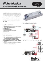
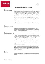
1: Product Description<br />
The <strong>Digidim</strong> <strong>498</strong> 8-channel relay unit is fitted with high inrush specification relays rated at 16 A per channel, which handle<br />
short-lived high peak inrush currents during switch-on of loads.<br />
The <strong>498</strong> can operate with either a <strong>Helvar</strong> <strong>Digidim</strong> or Imagine lighting control system and is DIN-rail mounted for ease of installation.<br />
The <strong>498</strong> has an intuitive LED segment display and push buttons known as the ‘Control Panel’, for monitoring, manual<br />
configuration and control purposes.<br />
The Control Panel comprises:<br />
• A 3-digit, 7-segment LED display (normally showing device activity)<br />
• Two buttons (‘up’ and ‘down’) to the right of the display, to view and configure parameters<br />
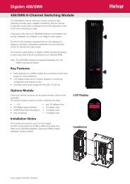
2: Installation<br />
2.1 2.2<br />
Location<br />
• For installation in a restricted access location only<br />
Position & Ventilation<br />
• Install the unit horizontally to allow for heat dissipation<br />
• Any enclosure must provide adequate cooling ventilation<br />
Cable information<br />
Cable Cable Type<br />
<strong>Helvar</strong> <strong>498</strong> <strong>Digidim</strong> DIN Rail 8-<strong>Channel</strong> <strong>Relay</strong> <strong>Unit</strong>: Installation and User guide<br />
Status<br />
Display<br />
Control panel<br />
Electrical<br />
• Do not connect DALI and S-DIM / DMX at the same time<br />
• Isolate the mains supply before installation<br />
• The external supply must be protected: 6 A MCB max.<br />
• All DALI and Mains cabling must be 230 V mains rated<br />
DALI 2-wire mains-rated. 0.5 mm² to 1.5 mm²<br />
Max. length 300 m (with 1.5 mm² cable). Example: Belden 8471<br />
Mains cable / <strong>Relay</strong>s Max. 2.5 mm² stranded (4 mm² solid).<br />
MAINS<br />
SUPPLY<br />
S-DIM / DMX Low loss RS485 Type (multi-stranded, twisted and shielded). Note: One twisted pair for A<br />
and B (85 Ω to 100 Ω impedance), one core or twisted pair for 0 V, and shield for screen.<br />
Size: 0.22 mm² to 1.5 mm². Core: 3 or 4 + Screen. Max. Length 1000 m (low-loss cable).<br />
Example: Belden 8102 or Alpha 6222C<br />
Override 2-wire. 0.5 mm² to 1.5 mm². Max. cable length 50 m<br />
DALI<br />
S-DIM / DMX<br />
OVERRIDE<br />
RELAY TERMINALS<br />
5 6<br />
RELAY TERMINALS<br />
3<br />
1<br />
2<br />
7<br />
8<br />
4
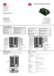
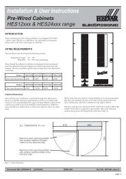
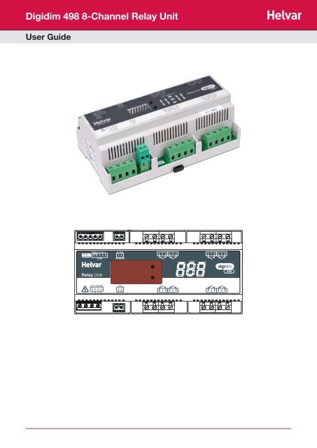
3: Connections<br />
S-DIM / DMX OVERRIDE<br />
TERM B SC 0V A 0V OVR<br />
L N E SC<br />
MAINS SUPPLY<br />
MAINS SUPPLY & DALI<br />
DA- DA+<br />
DALI<br />
MAINS SUPPLY DALI<br />
DALI<br />
Devices<br />
<strong>Helvar</strong> <strong>498</strong> <strong>Digidim</strong> DIN Rail 8-<strong>Channel</strong> <strong>Relay</strong> <strong>Unit</strong>: Installation and User guide<br />
5<br />
1<br />
Screen<br />
(if required)<br />
Note 1: Functional earth connection used for DALI /<br />
S-DIM / DMX screens only<br />
Note 2: Do NOT connect DALI and S-DIM/DMX at the<br />
same time<br />
6<br />
2<br />
RELAY OUTPUTS<br />
RELAY OUTPUTS<br />
S-DIM / DMX<br />
S-DIM or DMX<br />
OVERRIDE<br />
V in < 1.5 V<br />
I short = 1 mA<br />
i = S-DIM or DMX Data Cable (from previous device)<br />
ii = S-DIM or DMX Data Cable (to next device)<br />
iii = Link for Termination (if unit is at end of S-DIM/DMX cable line)<br />
Note: Keep unscreened wire lengths to a minimum<br />
7<br />
3<br />
8<br />
4<br />
Input for override<br />
Note: Maximum cable length = 50 m<br />
ii i<br />
i<br />
iii<br />
SW<br />
Close switch to<br />
cause level override<br />
3
4<br />
4: Power Up<br />
During power up, the following sequence is displayed on the LED Control Panel.<br />
Each display is held for one second. At the end of this sequence, the ‘Status’ display appears.<br />
Start-up Sequence:<br />
1. All segments on 2. Product model 3. Software version 4. Normal Operation<br />
(Status Display)<br />
Key and LED Descriptions:<br />
0.5 sec 0.5 sec 0.5 sec<br />
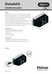
5. Understanding the Status Display<br />
The ’Status’ display is the default view in operation. It is the starting point for navigating and configuring the <strong>498</strong>.<br />
‘Power’ indicator<br />
The ‘power’ indicator (top segment of the middle digit) is always on when the <strong>498</strong> status display is active.<br />
S-DIM / DMX activity indicator<br />
The S-DIM / DMX activity indicator (centre segment of the middle digit) is normally off, and flashes on intermittently if any<br />
S-DIM / DMX activity (communications) is directed to a channel within the unit.<br />
<strong>Relay</strong> mimics<br />
The relay mimics (1, 2, 3, 4, 5, 6, 7 and 8) are illuminated when the relays are on, and not illuminated when the relays are off (0%).<br />
Software override indicator<br />
The decimal point on the left is illuminated to indicate software override from the 910 / 920 router. The middle segment of the<br />
display will also flash.<br />
DALI power / activity indicator<br />
The DALI indicator (bottom segment of the middle digit) is off if there is no DALI power, and on if DALI power is present. If any<br />
DALI activity is directed to a channel within the device, the indicator blinks off.<br />
Hardware (wired) override indicator<br />
The decimal point on the right is illuminated to indicate wired override. The middle segment of the display will also flash.<br />
<strong>Helvar</strong> <strong>498</strong> <strong>Digidim</strong> DIN Rail 8-<strong>Channel</strong> <strong>Relay</strong> <strong>Unit</strong>: Installation and User guide<br />
<strong>Relay</strong><br />
mimics:<br />
1 to 8<br />
5<br />
6<br />
Software<br />
override<br />
indicator<br />
‘Power’<br />
indicator<br />
S-DIM / DMX<br />
activity indicator<br />
7<br />
DALI<br />
power /<br />
activity<br />
indicator<br />
8<br />
Hardware<br />
(wired)<br />
override<br />
indicator<br />
‘Up’<br />
button<br />
‘Down’<br />
button
6. Navigating the <strong>498</strong> Menu<br />
The status display LEDs on the<br />
front of the unit are lit in the<br />
following way when power is on:<br />
Navigate the <strong>498</strong> menu to configure the unit.<br />
Cycle through the menu:<br />
1) Press both buttons simultaneously to cycle through the menus.<br />
Tip! To cycle through the menus quickly, hold down both buttons.<br />
Select the desired channel to modify:<br />
2) At your chosen function, quickly press up or down button to scroll<br />
through the channel destinations. These are the channels which will be<br />
affected by the following settings:<br />
Note: Select ‘ALL’ to alter all channels simultaneously.<br />
Modify function settings:<br />
3) Hold up or down buttons to alter the levels, settings, fade times, output<br />
modes (dependent on function activated).<br />
See section 7 for further details.<br />
Note: LEDs blink if the value has been changed and not yet stored.<br />
Save changes:<br />
4) Hold both buttons together to save the change.<br />
The LEDs will show 888 for 1 second to confirm setting is stored.<br />
Back To Previous Menu<br />
To go back to the previous menu, do not<br />
touch the buttons for 5 seconds.<br />
Back To Status Display<br />
10 seconds of inactivity returns the <strong>498</strong> to the Status Display screen.<br />
Tip! You can also return to the status display by cycling through all the<br />
menus.<br />
<strong>Helvar</strong> <strong>498</strong> <strong>Digidim</strong> DIN Rail 8-<strong>Channel</strong> <strong>Relay</strong> <strong>Unit</strong>: Installation and User guide<br />
Navigate through the <strong>498</strong> menus<br />
using the up / down push<br />
buttons located on the front of<br />
the unit.<br />
5 sec<br />
10 sec<br />
+<br />
-<br />
5
7. Configuring the <strong>498</strong><br />
Various settings can be configured via the control panel.<br />
Status Display / Set <strong>Channel</strong> Level<br />
Set <strong>Channel</strong> Levels (0 - 100%) by using the push buttons in ‘Status’ menu. Select the channel(s) to<br />
change, then hold the up or down button to alter levels.<br />
For further information, refer to the ‘Quick Start Guide’ in Section 10.<br />
Note: You can access ‘Status Display / Set channel level’ mode whilst the device is in override mode,<br />
but it is not possible to change the channel levels.<br />
Number of <strong>Channel</strong>s<br />
Set the number of device channels to 2, 4 or 8.<br />
Note: In 2-<strong>Channel</strong> mode: 1 + 2 + 3 + 4; 5 + 6 + 7 + 8<br />
In 4-<strong>Channel</strong> mode: 1 + 2; 3 + 4; 5 + 6; 7 + 8<br />
In 8-<strong>Channel</strong> mode: 1; 2; 3; 4; 5; 6; 7; 8<br />
Set S-DIM / DMX Address<br />
Set the S-DIM or DMX address for each channel.<br />
Select bAS to set the S-DIM or DMX base address.<br />
S-DIM: 252 addresses available.<br />
DMX: 512 addresses available.<br />
Note: DMX updates are disabled while using manual control.<br />
Set DALI Address<br />
Set the DALI address for each channel. Select bAS to set the DALI base address.<br />
DALI: 64 addresses available.<br />
Enable/Disable DMX<br />
Enable or disable DMX from this menu.<br />
When DMX is enabled (‘On’) it will use the S-DIM address.<br />
There is no channel select option; it is a global setting.<br />
Note: DMX is disabled by default.<br />
Minimum Fade Time<br />
Set the minimum fade time for the channels.<br />
Select the minimum fade time for each channel individually or ALL channels simultaneously.<br />
Minimum fade time can be set to: 1.00 second, 0.50 seconds, 0.15 seconds and 0.02 seconds.<br />
Override Level<br />
The override level can be configured for individual relay channels or ALL channels and ranges from 0 to<br />
100. It can be manually tested via the override test function (‘Ort’)<br />
Note 1: When S-DIM/DMX is connected, the override settings in the router (configured using Designer<br />
software) will take precedence over the device’s override settings, unless you configure the<br />
software to use the device override settings.<br />
Note 2: When the unit is running in override, the left decimal point is illuminated and the middle digit of<br />
the screen flashes in the status screen.<br />
6 <strong>Helvar</strong> <strong>498</strong> <strong>Digidim</strong> DIN Rail 8-<strong>Channel</strong> <strong>Relay</strong> <strong>Unit</strong>: Installation and User guide
Override Test<br />
Test that the override level (set in the previous mode) functions as required, by choosing ON or OFF. The<br />
unit performs as if an override has been caused by the override input connection.<br />
Note 1: By switching this setting to ON it will not be possible to manually edit the channel levels in<br />
‘Status Display / Set <strong>Channel</strong> Level’ menu.<br />
Note 2: To change the channel levels, ensure that override is switched off.<br />
Restore to Factory Default<br />
Hold the up or down buttons for 10 seconds in this menu.<br />
The decimal points will light up in sequence, and then all LEDs will be on for 1 second to confirm that<br />
factory settings have been restored.<br />
Note: Restore to Factory Default will cause all existing manually configured settings to be lost.<br />
8. Troubleshooting and Error Messages<br />
If an error occurs, please contact <strong>Helvar</strong> Support (see www.helvar.com for details).<br />
These details may be of assistance should an error message be displayed:<br />
Important considerations<br />
Switch-On Level (S-DIM / DMX only)<br />
Set the Switch-on levels for S-DIM / DMX channels.<br />
S-DIM: 2% – 64% (Default 2%);<br />
DMX: 0.1% - 64% (Default 0.1%)<br />
Set Minimum Level (DALI only)<br />
Set the minimum level for DALI channels.<br />
DALI: 0.1% - 100% (Default 0.1%)<br />
Note: The minimum level value will be overridden if the 454 is connected to a 910 or 920 router system.<br />
Communications Error (S-Dim/DMX only)<br />
ErC indicates a problem with the S-DIM or DMX communications. Please check wiring and terminations.<br />
Make sure no two channels have the same addresses on the network, and that the S-DIM / DMX mode<br />
is selected correctly.<br />
• Do not connect DALI and S-DIM / DMX at the same time.<br />
• If DMX does not work then please check that it has been switched on in the dMX menu. Then it is possible to set the DMX<br />
addresses in the Ads menu. See page 6 for further information.<br />
<strong>Helvar</strong> <strong>498</strong> <strong>Digidim</strong> DIN Rail 8-<strong>Channel</strong> <strong>Relay</strong> <strong>Unit</strong>: Installation and User guide<br />
7
9. DALI Physical Selection<br />
Physical selection mode allows loads and controls to be grouped together. It can be activated for a piece of equipment in<br />
a number of ways, including by using a <strong>Helvar</strong> remote control unit, or by using Designer or Toolbox software. Refer to the<br />
equipment instructions for details.<br />
Follow these steps to use the module to identify a piece of equipment using physical selection mode.<br />
Note 1: Use the Remote Control Handset, with a <strong>Digidim</strong> control device, to put the device into ‘Physical Selection’ mode. Refer<br />
to the ‘ <strong>Digidim</strong> Lighting Control – Designing, Specifying and Installing’ System Manual (doc. no. 7860038), section 5 - 7 Physical<br />
Selection.<br />
Note 2: The ‘Physical Selection’ display is identical to the ‘Status Display / Set <strong>Channel</strong> Level’ display, except for the decimal<br />
point flashing.<br />
1. Put the device into physical selection mode.<br />
The centre decimal point on the display screen flashes, which indicates that the device has entered<br />
‘Physical Selection’ mode.<br />
2. From the control panel, repeatedly press ‘up’ or ‘down’ button to scroll between channels.<br />
The selected channel mimic (s) flashes.<br />
3. To physically select the channel, hold the ‘up’ or ‘down’ button.<br />
The centre decimal point stops flashing for 2 seconds to indicate a successful programming.<br />
4. Repeat step 2 and 3 for each channel, as necessary.<br />
5. End ‘Physical Selection’ mode (at the device). You are returned to the ‘Status display.<br />
8 <strong>Helvar</strong> <strong>498</strong> <strong>Digidim</strong> DIN Rail 8-<strong>Channel</strong> <strong>Relay</strong> <strong>Unit</strong>: Installation and User guide
<strong>498</strong> Quick Start Guide<br />
10. <strong>498</strong> Quick Start Guide<br />
Navigation<br />
When desired level has been set, wait<br />
1 second for status screen to reappear. Press both buttons at the same time to<br />
+<br />
cycle through the menu.<br />
<strong>498</strong> Power On<br />
-<br />
Status /<br />
Set <strong>Channel</strong><br />
Level<br />
Press up or down button to scroll<br />
through the channel destinations.<br />
+<br />
-<br />
Set number<br />
of device<br />
channels<br />
Hold up or down button to alter the<br />
levels, settings, fade times, output<br />
modes (dependent on active mode).<br />
+<br />
-<br />
+<br />
-<br />
Set S-DIM<br />
or DMX<br />
Address<br />
Hold both buttons together to store the<br />
setting.<br />
Back to status display<br />
Set DALI<br />
Address<br />
Enable<br />
DMX<br />
Notes<br />
<strong>Helvar</strong> <strong>498</strong> <strong>Digidim</strong> DIN Rail 8-<strong>Channel</strong> <strong>Relay</strong> <strong>Unit</strong>: Installation and User guide<br />
+<br />
-<br />
10 seconds<br />
+<br />
-<br />
Select ALL channels<br />
Where available, select, ‘ALL’ to set all<br />
available channels.<br />
Variable level notice<br />
A UAr level notice occurs in certain<br />
modes if you are changing levels for<br />
ALL channels (via the ALL function) but<br />
the individual channel levels vary.<br />
Set DALI or S-DIM/DMX base addresses<br />
From the Add menu, select bAS to set<br />
the DALI base address.<br />
From the AdS menu, select bAS to set<br />
the S‑DIM or DMX base address.<br />
+<br />
Fade Time<br />
-<br />
+<br />
-<br />
Override<br />
Level<br />
+<br />
-<br />
Override<br />
Test<br />
+<br />
-<br />
Switch-on<br />
Level<br />
S-DIM/DMX only<br />
+<br />
-<br />
Set Minimum<br />
Level (DALI)<br />
All LEDs flash.<br />
Reset complete.<br />
+<br />
-<br />
10 seconds<br />
Restore to<br />
Factory<br />
Default<br />
Return to<br />
Status<br />
Mode<br />
9
Technical Data<br />
Connections<br />
Mains/relay: Solid core: up to 4 mm 2<br />
Stranded: 2.5 mm 2<br />
DALI: 0.5 mm 2 - 1.5 mm 2<br />
(max. 300 m @ 1.5 mm 2 )<br />
S-DIM / DMX: 0.22 mm² -1.5 mm² low loss RS485<br />
Type (multi-stranded, twisted and<br />
shielded)<br />
<strong>Relay</strong> channels: 2 channels per 4-way connector;<br />
2.5 mm² stranded<br />
Power<br />
Mains Supply: 85 - 264 VAC, 45 - 65 Hz<br />
Power Consumption: 2.6 W<br />
Power Circuit Protection: 6 A MCB maximum.<br />
The external supply must be protected.<br />
DALI Consumption: 2 mA<br />
Inputs<br />
Communication: DALI, S-DIM and DMX<br />
Override: Wired override input<br />
User interface: 2 push buttons for configuration<br />
<strong>Relay</strong> contacts<br />
<strong>Channel</strong>s: 8<br />
<strong>Relay</strong> contacts: High inrush (200 µs at 800 A), single<br />
pole normally open (SPNO)<br />
Max. load per contact: 16 A resistive / incandescent;<br />
10 A HID (cos y = 0.6)<br />
For ballasts, quantity is limited by MCB, refer to manufacturer’s<br />
data. <strong>Relay</strong> circuit external protection must not exceed 16 A<br />
type C MCB.<br />
Operating and Storage Conditions<br />
Ambient Temperature: 0°C to 40°C<br />
Relative Humidity: 90% max, non-condensing<br />
Storage Temperature: -10°C to +70°C<br />
Mechanical Data<br />
Housing: DIN-rail case; 9U<br />
Weight: 400 g<br />
IP Rating: IP30 (00 at terminals)<br />
Conformity and Standards<br />
DALI: According to DALI standard<br />
IEC 62386, with <strong>Helvar</strong> additions<br />
S-DIM: According to <strong>Helvar</strong> S-DIM protocol<br />
DMX: According to DMX512-A protocol<br />
Environment: Complies with WEEE and RoHS<br />
directives<br />
EMC<br />
Emission: EN 61000-6-3<br />
Immunity: EN 61 547<br />
Safety: EN 60 950<br />
Isolation: 4 kV between every connector (apart<br />
from common C0 ballast output<br />
terminals and S-DIM and Override<br />
connectors)<br />
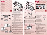
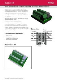
Dimensions<br />
160 mm<br />
www.helvar.com<br />
Data subject to change without notice Doc. 7860175, issue 03<br />
<strong>Helvar</strong> <strong>498</strong> <strong>Digidim</strong> DIN Rail 8-<strong>Channel</strong> <strong>Relay</strong> <strong>Unit</strong>: Installation and User guide 16:04:2012<br />
58mm<br />
45mm<br />
90mm