GIGAVAC GX11 High Power Contactor
GIGAVAC GX11 High Power Contactor
GIGAVAC GX11 High Power Contactor

You also want an ePaper? Increase the reach of your titles
YUMPU automatically turns print PDFs into web optimized ePapers that Google loves.
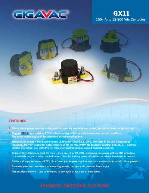
FEATURES<br />
G X11<br />
150+ Amp 12-800 Vdc <strong>Contactor</strong><br />
Chassis level power terminals – No need for specially routed power cables, special bus bars, or special lugs.<br />
Rugged EPIC® seal rated to 175°C – Reduced risk of fire or meltdown in over current conditions.<br />
The same technology used for advanced aerospace programs.<br />
Hermetically sealed – Designed to meet: UL1604 for Class I & II, Div 2 and Class III for use in hazardous<br />
locations, IP67 for temporary water immersion for 30 min, IP69K for pressure washing, SAE J1171 - external<br />
ignition protection, and ISO8846 for protection against ignition around flammable gasses.<br />
Optional <strong>High</strong> Efficiency Dual DC Coils – Very low 12 or 24 VDC continuous coil power with no EMI emissions<br />
or cross-talk on your system control power. Ideal for battery powered systems or where low power is needed.<br />
Built-in coil suppression for all DC coils – Saves you engineering time and parts cost to add external coil suppression.<br />
Stainless steel nuts, washers and mounting inserts, for years of corrosion free service.<br />
Not position sensitive – can be mounted in any position for ease of installation.<br />
ADVANCED SWITCHING SOLUTIONS
PRODUCT SPECIFICATIONS<br />
Specifications<br />
Contact Arrangement<br />
Units Data<br />
Main Form X SPST-NO<br />
Auxilary (2A, 24VDC) 1 Form A or B SPST-NO or<br />
SPST-NC<br />
Mechanical Life<br />
Contact Resistance<br />
Cycles 1,000,000<br />
2<br />
Max mohms 0.4<br />
Typical mohms 0.15 to 0.3<br />
Insulation Resistance4 Mohms 100<br />
Dielectric At Sea Level (Leakage < 1mA) VRMS 2,200<br />
Shock, 1/2 Sine, 11ms G peak 20<br />
Vibration, Sinusoidal (500-2000 Hz Peak)<br />
Ambient Temp Range<br />
G 15<br />
Operating5 ˚C -55 to +85<br />
Storage ˚C -70 to +150<br />
Weight, Typical Kg (Lb) 0.46 (1.0)<br />
Environmental Seal Exceeds IP67 & IP69K<br />
Salt Fog MIL-STD-810<br />
COIL RATINGS at 25˚C<br />
150+ Amp 12-800 Vdc<br />
EPIC® Hermetic Sealed DC and AC <strong>Contactor</strong><br />
POWER SWITCHING AND<br />
CURRENT CARRY RATINGS<br />
1,000,000<br />
Coil P/N Designation B C F H J K L S T<br />
Coil Voltage, Nominal (VDC)<br />
12 24 48 72 120<br />
120<br />
VAC<br />
240<br />
VAC<br />
CYCLES<br />
100,000<br />
12 24<br />
Coil Voltage, Max (V) 16 32 64 96 140 140 280 16 32<br />
10,000<br />
Pick-Up Voltage, Max (V) 7 7.5 15 28 46 72 80 144 96, 8 6, 8 15<br />
Drop-Out Voltage, Max (V) 7 3 7 10 14 18 30 56 4.5 7<br />
Drop-Out Voltage, Min (V) 7 0.5 0.5 1.8 2.7 4.5 4.5 9 1 1.5<br />
Pick-Up Current, Max (A)<br />
(75 ms) 7 N/A N/A N/A N/A N/A N/A N/A 1.7 0.76<br />
Coil Current (A) 7 0.68 0.28 0.16 0.095 0.06 0.06 0.04 0.084 0.032<br />
Coil <strong>Power</strong> (W) 7 8 6.8 7.6 6.8 7.2 7.2 9.6 1 0.768<br />
Operate Time, Max (ms) 3 20 20 30 30 20 30 30 20 20<br />
Release Time, Max (ms) 12 12 12 12 12 50 55 12 12<br />
Internal Coil Suppression<br />
CONTROL CIRCUIT<br />
Coil Back EMF (V) 55 55 80 115 175 N/A N/A 55 55<br />
Transients, Max (V) (13 ms) N/A N/A N/A N/A N/A N/A N/A ±50 ±50<br />
Reverse Polarity (V) N/A N/A N/A N/A N/A N/A N/A 16 32<br />
1,000<br />
DC POWER SWITCHING CYCLES 9<br />
G X11<br />
0 25 50 75 100 125 150<br />
TIME (sec)<br />
CURRENT (A)<br />
24V 300V 450V 600V<br />
10,000<br />
1,000<br />
100<br />
10<br />
CURRENT CARRY vs TIME<br />
with 85ºC terminal temperature rise<br />
325A max<br />
2/0 conductor<br />
225A max<br />
2 AWG conductor<br />
0 500 1,000 1,500 2,000<br />
CURRENT (A)<br />
2/0 2 AWG<br />
<strong>GIGAVAC</strong>® - P.O. Box 4428 - Santa Barbara, CA 93140-4428 - ph +(805) 684-8401 - fax +(805) 684-8402<br />
info@gigavac.com - www.gigavac.com - ©Copyright 2003-2013 <strong>GIGAVAC</strong>, LLC.
DIMENSIONS<br />
Mounting<br />
M5 Bolts<br />
Case Material<br />
DuPont Zytel FR50<br />
(25% Glass Filled Nylon)<br />
<strong>Power</strong> Connection<br />
Zinc Plated, Grade 8, M8x1.25 Bolt<br />
Stainless M8x1.25 Nut<br />
Stainless Lock Washer<br />
Stainless Flat Washer<br />
Torque 10Nm [90in-lb] max<br />
Coil Wire<br />
Silicone, 20 AWG, UL: VW-1<br />
2.36<br />
59.8<br />
0.92<br />
23.3<br />
0.40<br />
10.2<br />
0.21<br />
5.3<br />
0.79<br />
20<br />
0.95<br />
24.2<br />
MOUNTING<br />
150+ Amp 12-800 Vdc<br />
EPIC® Hermetic Sealed DC and AC <strong>Contactor</strong><br />
2.20<br />
55.9<br />
1.75<br />
44.5<br />
MOUNTING<br />
3.13<br />
79.5<br />
4.08<br />
103.6<br />
<strong>Power</strong> Contacts<br />
A2(+)<br />
A1(-)<br />
X2(-)<br />
X1(+)<br />
0.87<br />
22.1<br />
1.75<br />
44.5<br />
MOUNTING<br />
2.25<br />
57.3<br />
Auxiliary contacts<br />
(optional)<br />
NO:<br />
NC:<br />
T1<br />
T2<br />
T1<br />
T2<br />
G X11<br />
<strong>GIGAVAC</strong>® - P.O. Box 4428 - Santa Barbara, CA 93140-4428 - ph +(805) 684-8401 - fax +(805) 684-8402<br />
info@gigavac.com - www.gigavac.com - ©Copyright 2003-2013 <strong>GIGAVAC</strong>, LLC.
PART NUMBER SYSTEM<br />
<strong>GX11</strong> B A B<br />
Coil Voltage B = 12 Vdc, Internal Coil<br />
Suppression<br />
Coil<br />
Termination<br />
Auxiliary<br />
Contact<br />
C = 24 Vdc, Internal Coil<br />
Suppression<br />
F = 48 Vdc, Internal Coil<br />
Suppression<br />
H = 72 Vdc, Internal Coil<br />
Suppression<br />
J = 120 Vdc, Internal<br />
Coil Suppression<br />
K = 120 Vac, Internal<br />
Coil Suppression<br />
L = 240 Vac, Internal<br />
Coil Suppression<br />
S = 12 Vdc, Low <strong>Power</strong>,<br />
Internal Coil Suppression<br />
T = 24 Vdc, Low <strong>Power</strong>,<br />
Internal Coil Suppression<br />
APPLICATION NOTES<br />
A = Flying leads<br />
38 cm (15 in)<br />
B = Flying leads<br />
61 cm (24 in)<br />
C = Flying leads<br />
122 cm (48 in)<br />
• <strong>Contactor</strong>s feature internal transorb for coil suppression. No external<br />
diodes should be added across the coil. The use of additional external<br />
coil suppression can slow the release time and invalidate the life cycle<br />
ratings, or can cause the contactor not to be able to interrupt the<br />
maximum current specified. If lower coil back EMF is required, please<br />
contact <strong>GIGAVAC</strong> for assistance.<br />
• <strong>Contactor</strong>s should be installed so that current flows from A2(+) to A1(-).<br />
<strong>Contactor</strong>s should not be switched bi-directionally.<br />
• Applications with capacitors will require a pre-charge circuit.<br />
Blank = None<br />
B = SPST,<br />
Normally Open<br />
C = SPST,<br />
Normally Closed<br />
• Electrical life rating is based on resistive load with 27µH maximum<br />
inductance in circuit. Because your application may be different, we<br />
suggest you test the contactor in your circuit to verify life is as required.<br />
• End of life is defined as when the dielectric, insulation resistance or<br />
contact resistance fails the specifications listed.<br />
150+ Amp 12-800 Vdc<br />
EPIC® Hermetic Sealed DC and AC <strong>Contactor</strong><br />
Notes & Definitions:<br />
1 Auxillary contact rating is 2A, 24Vdc Resistive load, 100,000<br />
cycles. Minimum current is 0.1mA, 5V. The auxiliary contact is<br />
mechanically linked to the main power contacts.<br />
2 Contact resisitance measured at currents higher than 100A.<br />
3 Operation time is measured at 25°C and includes maximum<br />
7ms bounce.<br />
4 Insulation resistance is 50 Mohms after life.<br />
5 <strong>Contactor</strong> can operate up to 125°C in special cases - contact<br />
<strong>GIGAVAC</strong> for details.<br />
6 <strong>Contactor</strong> has two coils. Both are used for pick-up, and<br />
then in approximately 75 milliseconds, one coil is electronically<br />
removed from the coil drive circuit. The remaining coil supplies<br />
low continuous hold power sufficient for the contactor to meet<br />
all of its specified performance specifications. This provides low<br />
coil power without PWM electronics that can cause EMI emissions<br />
and/or cross-talk on control power.<br />
7 <strong>Contactor</strong> is operated by a coil that changes resistance<br />
with temperature. Since pick-up current, coil current and coil<br />
power are specified at nominal voltage, they will be lower than<br />
indicated at temperatures above 25°C and higher than indicated<br />
at temperatures below 25°C. Similarly, pick-up and drop-out<br />
voltages will be higher than indicated at temperatures above<br />
25°C and lower than indicated at temperatures below 25°C.<br />
8 For pick-up testing of contactors with dual coils, the voltage<br />
can not be ramped up slowly, but must be applied instantly to at<br />
least the maximum pick-up voltage. Otherwise, the contactor will<br />
not pick-up.<br />
9 Limit make current to 500A to avoid contact welding. For AC<br />
power switching cycles, contact factory.<br />
G X11<br />
<strong>GIGAVAC</strong>® - P.O. Box 4428 - Santa Barbara, CA 93140-4428 - ph +(805) 684-8401 - fax +(805) 684-8402<br />
info@gigavac.com - www.gigavac.com - ©Copyright 2003-2013 <strong>GIGAVAC</strong>, LLC.