PDF öffnen - Metallbau Schilloh GmbH
PDF öffnen - Metallbau Schilloh GmbH
PDF öffnen - Metallbau Schilloh GmbH

Create successful ePaper yourself
Turn your PDF publications into a flip-book with our unique Google optimized e-Paper software.
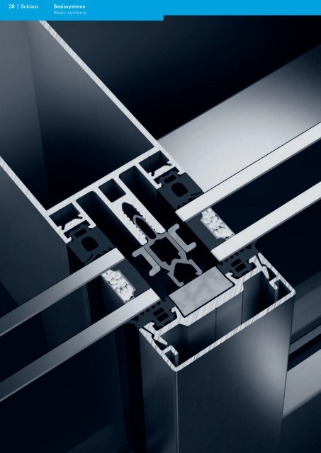
38 | Schüco<br />
Basissysteme<br />
Basic systems
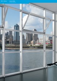
Schüco Fassade FW 50 + / FW 60 +<br />
Schüco Façade FW 50 + / FW 60 +<br />
Die Schüco Standardfassadensysteme<br />
FW 50 + und FW 60 +<br />
sind ausgereifte Lösungen,<br />
die sich millionenfach bewährt<br />
haben. Zusätzlich können die<br />
Fassadensysteme innherhalb<br />
der Schüco Systemwelt frei<br />
kombiniert werden. Damit sind<br />
der Kreativität fast keine<br />
Grenzen gesetzt.<br />
The Schüco standard façade<br />
systems FW 50 + and FW 60 + are<br />
tried and tested solutions, which<br />
have proven themselves time and<br />
again. In addition, the façade<br />
systems can be combined freely<br />
within the Schüco system world.<br />
There are no limits to creativity.<br />
Basissysteme<br />
Basic systems<br />
40 Systemeigenschaften<br />
System features<br />
42 Prüfzeugnisse<br />
Test certificates<br />
48 Konstruktionsprinzipien<br />
Construction principles<br />
53 Anwendungsbeispiele<br />
Examples<br />
86 Profilübersicht<br />
Profile overview<br />
110 Weiteres Zubehör<br />
Additional accessories<br />
Schüco | 39<br />
Basic systems<br />
Basissysteme
40 | Schüco<br />
Systemeigenschaften FW 50 + / FW 60 +<br />
System features of FW 50 + / FW 60 +<br />
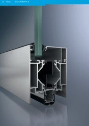
Systemeigenschaften FW 50 + / FW 60 +<br />
System features of FW 50 + / FW 60 +<br />
System FW 50 + .HI<br />
FW 50 + .HI system<br />
Maßstab 1:1<br />
Scale 1:1<br />
50<br />
50<br />
65<br />
Eigenschaften und Vorteile<br />
Riegel- und Pfostenprofile stehen in abgestuften<br />
Abmessungen je nach statischer Anforderung zur<br />
Verfügung<br />
Glaslasten: bis 400 kg bei FW 50 + und<br />
600 kg bei FW 60 +<br />
Profilgeometrie mit Falzgrunddrainage und<br />
wahlweise äußeren Dichtungssystemen:<br />
Einzel EPDM-Dichtungen mit Dichtungskreuzen<br />
Einzel EPDM-Dichtungen mit Butylbändern<br />
Durchgehende EPDM-Dichtung mit<br />
Dichtungskreuzen<br />
Isolator mit einseitiger Fahne<br />
Geprüft und gekenzeichnet durch Produktpass<br />
100 27203<br />
Gleiche innere Dichtungsansichten im Riegel und<br />
Pfosten<br />
Drei Entwässerungsebenen: Die Systeme FW 50 +<br />
und FW 60 + •<br />
•<br />
•<br />
•<br />
•<br />
•<br />
•<br />
•<br />
•<br />
•<br />
sind so konstruiert, dass die Glasfalze<br />
der Pfosten und Riegel in verschiedenen Ebenen<br />
liegen. Das eventuell auftretende Kondensat wird<br />
von der 1. Ebene in die 2. Ebene geleitet. Von hier<br />
erfolgt eine Weiterleitung in die 3. Ebene (Pfosten)<br />
und wird dann kontrolliert nach unten bzw.<br />
nach außen geführt. (Nur bei Gesamtbelüftung)<br />
• Die Falzgrundbelüftung sowie der Dampfdruckausgleich<br />
erfolgen über die 4 Ecken eines jeden<br />
Scheibenfeldes in den Pfostenfalz. Auf Anforderung<br />
ist auch eine feldweise Be- und Entlüftung<br />
ausführbar.<br />
• Für die Anwendung im Außenbereich sichtbare<br />
Schrauben aus Edelstahl-A4, alle nicht sichtbaren<br />
Schrauben in Edelstahl-A2<br />
• Isolatoren aus Polythermid® mit angepassten<br />
Wärmedämmeigenschaften<br />
• Spezialprofile für Wandanschluss, Dichtbahnanschlüsse<br />
und bauseitige Unterkonstruktionen<br />
sowie Einsatzelemente (Blockflügel, Lüftungsflügel,<br />
Türen, Dachfenster, Block-Konstruktion)<br />
und Fassadenbefestigungen sind vorhanden<br />
• Basisprofil zur einfachen Ausbildung von<br />
Fensterbändern<br />
• Basisprofil für den Übergang zur Kaltfassade
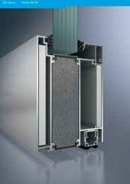
System FW 60 + .HI<br />
FW 60 + .HI system<br />
Maßstab 1:1<br />
Scale 1:1<br />
60<br />
60<br />
65<br />
Systemeigenschaften FW 50 + / FW 60 +<br />
System features of FW 50 + / FW 60 +<br />
Features and benefits<br />
Transom and mullion profiles are available in<br />
graduated dimensions to meet varying structural<br />
requirements.<br />
Glass loads: up to 400 kg with FW 50 + and<br />
600 kg with FW 60 +<br />
The geometry of the profiles allows rebate base<br />
drainage and one of the following outer gasket<br />
system options:<br />
EPDM gasket lengths with moulded<br />
intersections<br />
EPDM gasket lengths with butyl tape<br />
Continuous EPDM gasket with moulded<br />
intersections<br />
Isolator with fin on one side<br />
Tested and certified by product approval<br />
100 27203.<br />
Identical inner gasket cover on transoms and<br />
mullions.<br />
Three drainage levels: the FW 50 + and FW 60 +<br />
•<br />
•<br />
•<br />
•<br />
•<br />
•<br />
•<br />
•<br />
•<br />
•<br />
systems are designed in such a way that the glass<br />
rebates of the mullions and transoms lie in<br />
different planes. Any condensation is drained off<br />
from level 1 into level 2. Drainage continues<br />
through a third level in the mullions and<br />
downwards under controlled conditions to the<br />
outside. (for overall ventilation only)<br />
• Rebate base ventilation and pressure equalisation<br />
are achieved at all four corners of each module<br />
field into the mullion rebate. Field ventilation is<br />
available if required.<br />
• All external screws are A4 stainless steel, all other<br />
screws which are not visible are A2 stainless steel<br />
• Isolators made from polythermide® with<br />
appropriate thermal insulation<br />
• Special profiles for vapour barrier and wall<br />
attachment and for attachment to continuous<br />
substructures, plus a range of insert units (block<br />
windows, ventilation windows, doors, roof vents,<br />
fire-resistant block constructions) and façade<br />
fixing brackets<br />
• Base profile for simple ribbon window<br />
constructions<br />
•<br />
Base profile for the transition to the ventilated<br />
façade<br />
Schüco | 41<br />
Basic systems<br />
Basissysteme
42 | Schüco<br />
Prüfzeugnisse FW 50 + / FW 60 +<br />
Test certificates for FW 50 + / FW 60 +<br />
Prüfzeugnisse<br />
Test certificates<br />
System<br />
System<br />
FW 50 +<br />
Art der Prüfung<br />
Type of test<br />
Luftdurchlässigkeit<br />
Air permeability<br />
Schlagregendichtheit<br />
Watertightness<br />
Widerstand gegen Windlast<br />
Resistance to wind load<br />
Stossfestigkeit<br />
Impact strength<br />
Luftschalldämmung<br />
Airborne sound insulation<br />
Wärmedämmung<br />
Thermal insulation<br />
Längenbezogener Wärmedurchgang<br />
Length-related heat transfer<br />
Absturzsicherheit<br />
Safety barrier<br />
Einbruchhemmung<br />
Burglar resistance<br />
Durchschusshemmung<br />
Bullet resistance<br />
abZ für Klemmverbindung<br />
General building approval for clamping<br />
connectors<br />
abZ für T-Verbindungen<br />
General building approval for T-joints<br />
Luftdurchlässigkeit<br />
Air permeability<br />
Schlagregendichtheit<br />
Watertightness<br />
Widerstand gegen Windlast<br />
Resistance to wind load<br />
Air, Water, Structural, Seismic Interstory<br />
Movement<br />
Grundlage<br />
Basis<br />
EN 12152<br />
Prüfinstitut<br />
Test institute<br />
ift Rosenheim<br />
Nr. des Prüfzeugnisses/Bescheid<br />
No. of the test<br />
certificate / certificate<br />
10027203<br />
Prüfergebnis<br />
Test result<br />
EN 12154 RE 1200<br />
EN 12179<br />
EN 14019 I5 / E5<br />
EN ISO 717-1 16121404<br />
DIN EN ISO 10077, T2<br />
EN 13947<br />
EN ISO 10077, T2<br />
Siehe eigene Tabelle<br />
See own table<br />
Eigene Berechnung<br />
Own calculation<br />
ift Rosenheim 42734941/1<br />
DIN EN 12600 PSP Aachen S-47-01<br />
DIN EN V 1627 ift Rosenheim<br />
AE<br />
21125697 WK2<br />
21131294 WK3<br />
Zulässige Last = 2,0 kN/m 2<br />
Permitted load = 2,0 kN/m 2<br />
Erhöhte Last = 3,0 kN/m 2<br />
Increased load = 3,0 kN/m 2<br />
Siehe eigene Tabelle<br />
See own table<br />
Auf Anfrage<br />
On request<br />
EN 1522, T1 Beschussamt Ulm DSM 96247 M3 / FB4<br />
Bauregelliste<br />
Deutschland<br />
German building<br />
regulations<br />
CWCT<br />
DIBT<br />
Wintech<br />
Engineering<br />
Z-14.4.452<br />
Z-14.4.464<br />
R 134/01/199<br />
AAMA 501-5 ATI 55654.01-120-47<br />
Voll absturzsichernd<br />
Fully protected against falling out<br />
Siehe abZ<br />
See general building approval<br />
600 Pa<br />
1950 Pa<br />
2400 Pa<br />
(erhöhte Windlast = 3600 Pa)<br />
(Increased wind load = 3600 Pa)<br />
Auf Anfrage<br />
On request
System<br />
System<br />
FW 60 +<br />
Art der Prüfung<br />
Type of test<br />
Luftdurchlässigkeit<br />
Air permeability<br />
Schlagregendichtheit<br />
Watertightness<br />
Widerstand gegen Windlast<br />
Resistance to wind load<br />
Stossfestigkeit<br />
Impact strength<br />
Luftschalldämmung<br />
Airborne sound insulation<br />
Wärmedurchgang<br />
Thermal conduction<br />
Absturzsicherheit<br />
Safety barrier<br />
Einbruchhemmung<br />
Burglar resistance<br />
Durchschusshemmung<br />
Bullet resistance<br />
Sprengwirkungshemmung<br />
Blast resistance<br />
abZ für Klemmverbindung<br />
General building approval for clamping<br />
connectors<br />
abZ für T-Verbindungen<br />
General building approval for T-joints<br />
Luftdurchlässigkeit<br />
Air permeability<br />
Schlagregendichtheit<br />
Watertightness<br />
Widerstand gegen Windlast<br />
Resistance to wind load<br />
Air, Water, Structural, Seismic Interstory<br />
Movement<br />
Grundlage<br />
Basis<br />
EN 12152<br />
Prüfinstitut<br />
Test institute<br />
ift Rosenheim<br />
Prüfzeugnisse FW 50 + / FW 60 +<br />
Test certificates for FW 50 + / FW 60 +<br />
Nr. des Prüfzeugnisses/Bescheid<br />
No. of the test<br />
certificate / certificate<br />
10027203<br />
Prüfergebnis<br />
Test result<br />
EN 12154 RE 1200<br />
EN 12179<br />
EN 14019 I5 / E5<br />
EN ISO 717-1 16122335<br />
DIN EN ISO 10077, T2<br />
Eigene Berechnung<br />
Own calculation<br />
DIN EN 12600 PSP Aachen S-47-01<br />
DIN EN V 1627 ift Rosenheim<br />
Siehe eigene Tabelle<br />
See own table<br />
AE<br />
21125697 WK2<br />
21125698 WK3<br />
EN 1522, T1 Beschussamt Ulm DSM 96247 M3 / FB4<br />
Freilandversuch<br />
US-GSA Vorschriften<br />
Outdoor test US-GSA<br />
regulations<br />
Bauregelliste<br />
Deutschland<br />
German building<br />
regulations<br />
CWCT<br />
TNO PML 2004-C063<br />
DIBT<br />
Wintech<br />
Engineering<br />
Z-14.4.452<br />
Z-14.4.464<br />
R 134/01/199<br />
AAMA 501-5 ATI 57614.01-122-34-RO<br />
Zulässige Last = 2,0 kN/m 2<br />
Permitted load = 2,0 kN/m 2<br />
Erhöhte Last = 3,0 kN/m 2<br />
Increased load = 3,0 kN/m 2<br />
Siehe eigene Tabelle<br />
See own table<br />
Voll absturzsichernd<br />
Fully protected against falling out<br />
Leistungsbedingung 2<br />
Performance requirement 2<br />
Siehe abZ<br />
See general building approval<br />
600 Pa<br />
1950 Pa<br />
2400 Pa<br />
(erhöhte Windlast = 3600 Pa)<br />
(Increased wind load = 3600 Pa)<br />
Auf Anfrage<br />
On request<br />
Schüco | 43<br />
Basic systems<br />
Basissysteme
44 | Schüco<br />
Prüfzeugnisse FW 50 + / FW 60 +<br />
Test certificates for FW 50 + / FW 60 +<br />
Für die unterschiedlichen Schallschutzanforderungen<br />
bieten sich<br />
folgende Schüco-Systeme an:<br />
Bewertetes Schalldämm-Maß<br />
Weighted sound insulation<br />
factor<br />
R w, p = 37 dB<br />
R w, p = 41 dB<br />
R w, p = 42 dB<br />
R w, p = 49 dB<br />
Hinweis:<br />
Bei Verwendung von Schallschutzgläsern ist darauf zu<br />
achten, daß die vom Lieferanten für das Glas<br />
angegebenen Schalldämmwerte nach der neusten<br />
Prüfnorm übermittelt wurden.<br />
The following Schüco systems<br />
fulfil the various noise reduction<br />
requirements:<br />
Schüco-System<br />
Schüco system<br />
Pfosten<br />
Mullion<br />
322 280<br />
Pfosten<br />
Mullion<br />
322 280<br />
Pfosten<br />
Mullion<br />
322 280<br />
Pfosten<br />
Mullion<br />
322 280<br />
Note:<br />
When using noise reduction glazing, it is important<br />
to ensure that the noise reduction values given by<br />
the supplier have been adopted in accordance with<br />
the most recent test norms.<br />
Nr. des Prüfzeugnisses<br />
No. of the test<br />
certificate<br />
FW 50 + 161 21404<br />
FW 50 + 161 21404<br />
FW 50 + 161 21404<br />
FW 50 + 161 21404<br />
Empfohlene Verglasung<br />
Recommended glazing<br />
Schalldämmverglasung<br />
Noise reduction glazing<br />
R w = 38 dB<br />
[6-(16)-4]<br />
Schalldämmverglasung<br />
Noise reduction glazing<br />
Schalldämmverglasung<br />
Noise reduction glazing<br />
R w = 45 dB<br />
[9 GH-(16)-6]<br />
Schalldämmverglasung<br />
Noise reduction glazing
Bewertetes Schalldämm-Maß<br />
Weighted sound insulation<br />
factor<br />
Schüco-System<br />
Schüco system<br />
Prüfzeugnisse FW 50 + / FW 60 +<br />
Test certificates for FW 50 + / FW 60 +<br />
Nr. des Prüfzeugnisses<br />
No. of the test certificate<br />
R w, p = 37 dB FW 60 + 161 22335/1.3.0<br />
R w, p = 41 dB FW 60 + 161 22335/1.2.0<br />
R w, p = 42 dB FW 60 + 161 22335/1.1.0<br />
R w, p = 49 dB FW 60 + 161 22335/1.0.0<br />
Hinweis:<br />
Bei Verwendung von Schallschutzgläsern ist darauf zu<br />
achten, daß die vom Lieferanten für das Glas<br />
angegebenen Schalldämmwerte nach der neusten<br />
Prüfnorm übermittelt wurden.<br />
Note:<br />
When using noise reduction glazing, it is important<br />
to ensure that the noise reduction values given by<br />
the supplier have been adopted in accordance with<br />
the most recent test norms.<br />
Empfohlene Verglasung<br />
Recommended glazing<br />
Phonstop 26/38<br />
[6-(16)-4]<br />
Phonstop 26/38<br />
[6-(16)-4]<br />
Phonstop 36/42<br />
[12-(20)-4]<br />
Phonstop 36/42<br />
[12-(20)-4]<br />
Phonstop 31/45 GH<br />
[9GH-(16)-6]<br />
Phonstop 31/45 GH<br />
[9GH-(16)-6]<br />
Phonstop 42/54 GH<br />
[13GH-(20)-9GH]<br />
Phonstop 42/54 GH<br />
[13GH-(20)-9GH]<br />
Schüco | 45<br />
Basic systems<br />
Basissysteme
46 | Schüco<br />
Prüfzeugnisse FW 50 + / FW 60 +<br />
Test certificates for FW 50 + / FW 60 +<br />
Wärmedämmung<br />
Thermal insulation<br />
U f -Wert in W/m 2 K nach DIN EN ISO 10077, T2<br />
U f value in W/m 2 K in accordance with DIN EN ISO 10077, T2<br />
x<br />
50<br />
50<br />
Maßstab 1:2<br />
Scale 1:2<br />
50 65 85 105 125 150 175 200 225 250<br />
U f = [W/m 2 K]*<br />
24 - 28 1,60 1,60 1,61 1,62 1,62 1,63 1,64 1,64 1,65 1,66<br />
28 - 32 1,44 1,44 1,45 1,46 1,46 1,47 1,48 1,48 1,49 1,50<br />
34 - 38 1,35 1,35 1,36 1,37 1,37 1,38 1,39 1,39 1,40 1,41<br />
40 - 44 1,16 1,16 1,17 1,18 1,18 1,19 1,20 1,20 1,21 1,22<br />
46 - 50 1,08 1,08 1,09 1,10 1,10 1,11 1,12 1,12 1,13 1,14<br />
* Die U f -Werte der Riegel-Ebenen 1 und 2<br />
entsprechen denen von Pfosten, Ebene 3.<br />
The U f values listed apply to level 3 and are<br />
therefore lower than for levels 1 and 2.<br />
Für das Fassadensystem FW 50 +<br />
sind die tatsächlichen längen-<br />
bezogenen Wärmedurchgangs-<br />
koeffizienten (Ψ-Wert) durch den<br />
Prüfbericht 427 34941/1 belegt.<br />
The length-related heat transfer<br />
coefficients (Ψ value) for the<br />
FW 50 + façade system are<br />
documented in the test report<br />
427 34941/1.
x<br />
60<br />
60<br />
Prüfzeugnisse FW 50 + / FW 60 +<br />
Test certificates for FW 50 + / FW 60 +<br />
50 65 85 105 125 150 175 200 225 250<br />
U f = [W/m 2 K]*<br />
24 - 28 1,60 1,60 1,61 1,62 1,62 1,63 1,64 1,64 1,65 1,66<br />
28 - 32 1,44 1,44 1,45 1,46 1,46 1,47 1,48 1,48 1,49 1,50<br />
34 - 38 1,35 1,35 1,36 1,37 1,37 1,38 1,39 1,39 1,40 1,41<br />
40 - 44 1,16 1,16 1,17 1,18 1,18 1,19 1,20 1,20 1,21 1,22<br />
46 - 50 1,08 1,08 1,09 1,10 1,10 1,11 1,12 1,12 1,13 1,14<br />
* Die U f -Werte der Riegel-Ebenen 1 und 2<br />
entsprechen denen von Pfosten, Ebene 3.<br />
The U f values listed apply to level 3 and are<br />
therefore lower than for levels 1 and 2.<br />
Maßstab 1:2<br />
Scale 1:2<br />
Schüco | 47<br />
Basic systems<br />
Basissysteme
48 | Schüco<br />
Konstruktionsprinzipien FW 50 + / FW 60 +<br />
Construction principles for FW 50 + / FW 60 +<br />
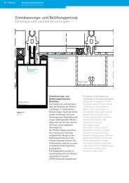
Entwässerungs- und Belüftungsprinzip<br />
Drainage and ventilation principle<br />
Pfosten (3. Ebene)<br />
Mullion (level 3)<br />
Maßstab 1:1<br />
Scale 1:1<br />
Drainagenut<br />
Drainage channel<br />
EPDM-Dichtstück<br />
EPDM seal<br />
Entwässerungs- und<br />
Belüftungsprinzip des<br />
Glasfalzes<br />
Das System ist so konstruiert,<br />
dass die Glasfalze der Pfosten<br />
und Riegel in verschiedenen<br />
Ebenen liegen. Eventuell auftretendes<br />
Kondensat wird vom<br />
höherliegenden Riegelfalzgrund<br />
in den tieferliegenden Pfostenfalzgrund<br />
und von dort kontrolliert<br />
nach unten abgeleitet<br />
(Drainagenut).<br />
Der Pfosten-Riegel-Anschluss<br />
ist so konstruiert, dass die<br />
ausgeklinkten Riegel auf der<br />
Dichtungsaufnahmenut der<br />
Pfosten befestigt werden. Der<br />
Höhenversatz wird durch unterschiedliche<br />
Dichtungshöhen<br />
ausgeglichen.<br />
Die Riegelprofile werden im<br />
Anschlussbereich zum Pfosten<br />
unterseitig mit einem<br />
EPDM-Dichtprofil abgedichtet.<br />
Riegel (1. Ebene)<br />
Transom (level 1)<br />
Principles of drainage and<br />
ventilation in the glazing rebate<br />
The system is designed so that<br />
the glass rebates of the mullions<br />
and transoms lie in different<br />
planes. Any condensation is<br />
drained from the higher transom<br />
glazing rebate into the lower<br />
mullion glazing rebate and then<br />
drained downwards under<br />
controlled conditions<br />
(drainage channel).<br />
The mullion transom joint is<br />
designed so that the notched<br />
transoms are secured to the<br />
gasket locating grooves. Different<br />
gasket thicknesses compensate<br />
for the differences in height.<br />
The transom profiles are sealed<br />
underneath with an EPDM gasket<br />
at the point at which they<br />
connect to the mullion.
H<br />
H<br />
H<br />
Riegel (1. Ebene)<br />
Transom (level 1)<br />
Riegel (2. Ebene)<br />
Transom (level 2)<br />
Pfosten (3. Ebene)<br />
Mullion (level 3)<br />
Konstruktionsprinzipien FW 50 + / FW 60 +<br />
Construction principles for FW 50 + / FW 60 +<br />
H = gleiche Höhe<br />
H = same height<br />
= Ebenen<br />
Levels<br />
Schüco | 49<br />
Basic systems<br />
Basissysteme
50 | Schüco<br />
Konstruktionsprinzipien FW 50 + / FW 60 +<br />
Construction principles for FW 50 + / FW 60 +<br />
Gesamtbelüftung und Entwässerung<br />
Overall ventilation and drainage<br />
Kopfpunkt<br />
Head<br />
H 8<br />
Fußpunkt<br />
Sill<br />
Falzstück<br />
Deflector block<br />
Der Dampfdruckausgleich des<br />
Glasfalz im Riegelbereich erfolgt<br />
seitlich in den Pfostenfalz<br />
(Drainagenut). So wird jedes<br />
einzelne Scheibenfeld über alle<br />
vier Ecken “belüftet”. Eine<br />
kontrollierte Entwässerung<br />
erfolgt entlang des Pfostens.<br />
Pressure is equalised through the<br />
glass rebates of the transoms<br />
into the mullion rebates (drainage<br />
channel). In this way, each pane<br />
field is ventilated at all four<br />
corners. Controlled drainage<br />
takes place along the length of<br />
the mullion.<br />
Kopfpunkt<br />
Head<br />
H > 8<br />
Fußpunkt<br />
Sill<br />
H 8
Kopfpunkt<br />
Head<br />
Fußpunkt<br />
Sill<br />
Dichtstück<br />
Seal<br />
Konstruktionsprinzipien FW 50 + / FW 60 +<br />
Construction principles for FW 50 + / FW 60 +<br />
Feldweise Belüftung und<br />
Entwässerung<br />
Bei der feldweisen Belüftung<br />
und Entwässerung wird das<br />
anfallende Kondensat pro Feld<br />
nach außen abgeleitet. Dazu wird<br />
das Kondensat über Endstücke in<br />
den Riegel abgeleitet. Von dort<br />
wird das Kondensat über Aussparungen<br />
in der äußeren Dicht-<br />
ebene des Riegels nach außen<br />
abgeleitet. Auch die Belüftung<br />
erfolgt über diese Aussparungen.<br />
Field drainage and ventilation<br />
In terms of ventilation and<br />
drainage, the resulting<br />
condensation per field is<br />
conducted to the outside. In<br />
addition, the condensation will be<br />
drained over the end pieces into<br />
the transom. From there the<br />
condensation will be drained via<br />
the recesses into the external<br />
sealing level of the transom.<br />
Ventilation also takes place<br />
via these recesses.<br />
Abschluss des Riegels zum Pfostenfalzgrund<br />
Closing the transom to the mullion rebate base<br />
Be- und Entlüftung erfolgt über den<br />
Riegelfalzgrund<br />
Ventilation takes place via the transom<br />
rebate base<br />
Schüco | 51<br />
Basic systems<br />
Basissysteme
52 | Schüco<br />
Konstruktionsprinzipien FW 50 + / FW 60 +<br />
Construction principles for FW 50 + / FW 60 +<br />
Maximale Glaslasten in Abhängigkeit vom Scheibenaufbau<br />
Maximum glass load is dependent on the glazing<br />
Hinweis:<br />
Statisch entsprechend dimensionierte<br />
Riegel und T-Verbinder<br />
werden vorausgesetzt.<br />
Maßstab 1:1<br />
Scale 1:1<br />
Note:<br />
Please ensure that the transoms<br />
and T-cleats are the correct size<br />
to meet the structural<br />
requirements.<br />
x<br />
32 - 38 400<br />
40 - 50 375<br />
24 - 38 600<br />
40 - 44 550<br />
46 - 50 500<br />
x<br />
20 - 24 185<br />
24 - 28 170<br />
28 - 32 150<br />
34 - 38 125<br />
40 - 44 100<br />
44 - 48 75<br />
20 - 24 185<br />
24 - 28 170<br />
28 - 32 150<br />
34 - 38 125<br />
40 - 44 100<br />
46 - 50 75<br />
kg<br />
kg
82<br />
85<br />
84<br />
Anwendungsbeispiele FW 50 + / FW 60 +<br />
Examples for FW 50 + / FW 60 +<br />
Die hier gezeigten Element-<br />
symbole geben eine Übersicht<br />
der möglichen Bauformen. Alle<br />
auf dieser Seite angegebenen<br />
Zahlen sind Seitenzahlen zu den<br />
im Folgenden gezeigten<br />
Anwendungsbeispielen.<br />
76<br />
54<br />
56<br />
71<br />
83<br />
77<br />
54<br />
55<br />
56<br />
57<br />
58<br />
69<br />
70<br />
80<br />
65<br />
67<br />
68<br />
59<br />
72<br />
73<br />
The diagrams shown here provide<br />
an overview of the different<br />
shapes that are possible. The<br />
numbers below are the page<br />
numbers for the relevant<br />
examples.<br />
Anwendungsbeispiele FW 50 + / FW 60 +<br />
Examples for FW 50 + / FW 60 +<br />
60<br />
61<br />
62<br />
63<br />
74<br />
75<br />
78<br />
79<br />
64<br />
66<br />
Schüco | 53<br />
Basic systems<br />
Basissysteme
54 | Schüco<br />
Anwendungsbeispiele FW 50 + / FW 60 +<br />
Examples for FW 50 + / FW 60 +<br />
Hochwärmegedämmte Fassade<br />
High insulation façade<br />
50<br />
50<br />
20 5 28 13<br />
15 5 28 7<br />
70<br />
Maßstab 1:1<br />
Scale 1:1
Montagepfosten<br />
Assembly mullion<br />
Maßstab 1:1<br />
Scale 1:1<br />
22<br />
50<br />
6<br />
50<br />
22<br />
11 105<br />
Anwendungsbeispiele FW 50 + / FW 60 +<br />
Examples for FW 50 + / FW 60 +<br />
15 26<br />
3.5<br />
Schüco | 55<br />
Basic systems<br />
Basissysteme
56 | Schüco<br />
Anwendungsbeispiele FW 50 + / FW 60 +<br />
Examples for FW 50 + / FW 60 +<br />
Kabelführung<br />
Cable guide<br />
Maßstab 1:2<br />
Scale 1:2<br />
50<br />
130<br />
58<br />
50
Kabelführung bei Photovoltaik-Modulen<br />
Cable guide for photovoltaic modules<br />
Kabelführung horizontal<br />
Horizontal cable guide<br />
Maßstab 1:2<br />
Scale 1:2<br />
Anwendungsbeispiele FW 50 + / FW 60 +<br />
Examples for FW 50 + / FW 60 +<br />
Kabelführung vertikal<br />
Vertical cable guide<br />
50 50<br />
Schüco | 57<br />
Basic systems<br />
Basissysteme
58 | Schüco<br />
Anwendungsbeispiele FW 50 + / FW 60 +<br />
Examples for FW 50 + / FW 60 +<br />
Flache Deckschale<br />
Flat cover caps<br />
Maßstab 1:1<br />
Scale 1:1<br />
50<br />
50<br />
1.8 1.8<br />
26 13<br />
3.5
Außenecke<br />
Outer corner<br />
Maßstab 1:1<br />
Scale 1:1<br />
85<br />
Anwendungsbeispiele FW 50 + / FW 60 +<br />
Examples for FW 50 + / FW 60 +<br />
50<br />
85<br />
Schüco | 59<br />
Basic systems<br />
Basissysteme
60 | Schüco<br />
Anwendungsbeispiele FW 50 + / FW 60 +<br />
Examples for FW 50 + / FW 60 +<br />
Außen-Segmentierung 0° - 10°<br />
External faceting 0° - 10°<br />
26<br />
0° - 10°<br />
Maßstab 1:1<br />
Scale 1:1<br />
85<br />
50<br />
50<br />
0° - 10°
Außen-Segmentierung 10° - 15°<br />
External faceting 10° - 15°<br />
10° - 15°<br />
Maßstab 1:1<br />
Scale 1:1<br />
13<br />
50<br />
60<br />
10° - 15°<br />
Anwendungsbeispiele FW 50 + / FW 60 +<br />
Examples for FW 50 + / FW 60 +<br />
26<br />
Schüco | 61<br />
Basic systems<br />
Basissysteme
62 | Schüco<br />
Anwendungsbeispiele FW 50 + / FW 60 +<br />
Examples for FW 50 + / FW 60 +<br />
Außen-Segmentierung 0° - 25°<br />
External faceting 0° - 25°<br />
25°<br />
26<br />
Maßstab 1:1<br />
Scale 1:1<br />
18<br />
92<br />
50<br />
85 - 200<br />
18<br />
60 25°
34°<br />
Einseitig variable Außen-Segmentierung<br />
Variable angle external faceting on one side<br />
26<br />
Maßstab 1:1<br />
Scale 1:1<br />
34<br />
60<br />
50<br />
Anwendungsbeispiele FW 50 + / FW 60 +<br />
Examples for FW 50 + / FW 60 +<br />
105<br />
26<br />
Schüco | 63<br />
Basic systems<br />
Basissysteme
64 | Schüco<br />
Anwendungsbeispiele FW 50 + / FW 60 +<br />
Examples for FW 50 + / FW 60 +<br />
Innen-Segmentierung 0° - 10°<br />
Internal faceting 0° - 10°<br />
26<br />
0° - 10°<br />
Maßstab 1:1<br />
Scale 1:1<br />
85<br />
50<br />
50<br />
0° - 10°<br />
15
Innenecke 90°<br />
90° inner corner<br />
Maßstab 1:1<br />
Scale 1:1<br />
90°<br />
50<br />
50<br />
50<br />
Anwendungsbeispiele FW 50 + / FW 60 +<br />
Examples for FW 50 + / FW 60 +<br />
50<br />
Schüco | 65<br />
Basic systems<br />
Basissysteme
66 | Schüco<br />
11<br />
26<br />
Anwendungsbeispiele FW 50 + / FW 60 +<br />
Examples for FW 50 + / FW 60 +<br />
Variable Innen-Segmentierung<br />
Variable angle internal faceting<br />
Maßstab 1:1<br />
Scale 1:1<br />
50<br />
50<br />
90° - 180°
Innenecke 90° sichtbar geschraubt<br />
90° inner corner with visible screw fixings<br />
92<br />
Maßstab 1:1<br />
Scale 1:1<br />
50<br />
85<br />
50 11 26<br />
Anwendungsbeispiele FW 50 + / FW 60 +<br />
Examples for FW 50 + / FW 60 +<br />
8<br />
3.5<br />
13 - 20<br />
90°<br />
Schüco | 67<br />
Basic systems<br />
Basissysteme
68 | Schüco<br />
92<br />
Anwendungsbeispiele FW 50 + / FW 60 +<br />
Examples for FW 50 + / FW 60 +<br />
Innenecke 90° unsichtbar befestigt<br />
90° inner corner with concealed fixings<br />
Maßstab 1:1<br />
Scale 1:1<br />
50<br />
85<br />
50 11 26<br />
3.5<br />
15<br />
13 - 20<br />
90°
Vertikaler Pfosten mit Trockenverglasung<br />
Vertical mullion with dry glazing<br />
Maßstab 1:1<br />
Scale 1:1<br />
50<br />
30<br />
26 11 105<br />
100<br />
Anwendungsbeispiele FW 50 + / FW 60 +<br />
Examples for FW 50 + / FW 60 +<br />
Schüco | 69<br />
Basic systems<br />
Basissysteme
70 | Schüco<br />
Anwendungsbeispiele FW 50 + / FW 60 +<br />
Examples for FW 50 + / FW 60 +<br />
Pfostenschnitt mit vertikaler Siliconfuge (Versiegelung)<br />
Mullion section detail with vertical silicone joint (sealing)<br />
13<br />
26<br />
3.5<br />
100<br />
Maßstab 1:1<br />
Scale 1:1<br />
50<br />
15 20 15
Riegelschnitt<br />
Transom detail<br />
Maßstab 1:1<br />
Scale 1:1<br />
Anwendungsbeispiele FW 50 + / FW 60 +<br />
Examples for FW 50 + / FW 60 +<br />
100<br />
3.5<br />
26 7<br />
Schüco | 71<br />
Basic systems<br />
Basissysteme
72 | Schüco<br />
Anwendungsbeispiele FW 50 + / FW 60 +<br />
Examples for FW 50 + / FW 60 +<br />
Ganzglasecke Typ 1<br />
All-glass corner type 1<br />
Maßstab 1:2<br />
Scale 1:2
Ganzglasecke Typ 2<br />
All-glass corner type 2<br />
Maßstab 1:2<br />
Scale 1:2<br />
Anwendungsbeispiele FW 50 + / FW 60 +<br />
Examples for FW 50 + / FW 60 +<br />
Schüco | 73<br />
Basic systems<br />
Basissysteme
74 | Schüco<br />
Anwendungsbeispiele FW 50 + / FW 60 +<br />
Examples for FW 50 + / FW 60 +<br />
HI-Konstruktion im Schrägdachbereich<br />
HI construction in sloped roof area<br />
Maßstab 1:1<br />
Scale 1:1<br />
50<br />
10<br />
50<br />
205 832<br />
10
3.5<br />
8.5<br />
Dichtung mit Kondenswasserableitung<br />
Gasket with condensation drainage<br />
12<br />
Maßstab 1:1<br />
Scale 1:1<br />
30<br />
50<br />
5<br />
Anwendungsbeispiele FW 50 + / FW 60 +<br />
Examples for FW 50 + / FW 60 +<br />
50<br />
Schüco | 75<br />
30<br />
11<br />
Basic systems<br />
Basissysteme
76 | Schüco<br />
Anwendungsbeispiele FW 50 + / FW 60 +<br />
Examples for FW 50 + / FW 60 +<br />
Variabler Riegel<br />
Variable angle transoms<br />
38° - 90°<br />
Maßstab 1:1<br />
Scale 1:1<br />
50<br />
50<br />
26 5 55<br />
30 5<br />
28<br />
55
Riegel-Innenecke<br />
Transom inner corner<br />
Maßstab 1:1<br />
Scale 1:1<br />
50<br />
50<br />
Anwendungsbeispiele FW 50 + / FW 60 +<br />
Examples for FW 50 + / FW 60 +<br />
26 5 55<br />
45°<br />
Schüco | 77<br />
50<br />
Basic systems<br />
Basissysteme
78 | Schüco<br />
Anwendungsbeispiele FW 50 + / FW 60 +<br />
Examples for FW 50 + / FW 60 +<br />
Firstpfette<br />
Ridge purlins<br />
Maßstab 1:1<br />
Scale 1:1<br />
30 5 55<br />
28<br />
50
Firstpfette, alternative Ausführung<br />
Ridge purlins, alternative version<br />
Maßstab 1:2<br />
Scale 1:2<br />
Anwendungsbeispiele FW 50 + / FW 60 +<br />
Examples for FW 50 + / FW 60 +<br />
Schüco | 79<br />
Basic systems<br />
Basissysteme
80 | Schüco<br />
Anwendungsbeispiele FW 50 + / FW 60 +<br />
Examples for FW 50 + / FW 60 +<br />
Innentrennwand<br />
Interior wall<br />
Maßstab 1:2<br />
Scale 1:2
Kopfpunkt als Attika<br />
Head of façade as fascia<br />
50<br />
50<br />
Maßstab 1:4<br />
Scale 1:4<br />
Anwendungsbeispiele FW 50 + / FW 60 +<br />
Examples for FW 50 + / FW 60 +<br />
Schüco | 81<br />
Basic systems<br />
Basissysteme
82 | Schüco<br />
Anwendungsbeispiele FW 50 + / FW 60 +<br />
Examples for FW 50 + / FW 60 +<br />
Anschluss an Brüstung<br />
Connection to spandrel panel<br />
Maßstab 1:4<br />
Scale 1:4<br />
50 50
W90 Brüstung<br />
W90 spandrel panel<br />
A<br />
Maßstab 1:4<br />
Scale 1:4<br />
A<br />
Anwendungsbeispiele FW 50 + / FW 60 +<br />
Examples for FW 50 + / FW 60 +<br />
A - A<br />
Schüco | 83<br />
Basic systems<br />
Basissysteme
84 | Schüco<br />
Fußpunkt<br />
Sill<br />
Maßstab 1:2<br />
Scale 1:2<br />
Anwendungsbeispiele FW 50 + / FW 60 +<br />
Examples for FW 50 + / FW 60 +<br />
50
Seitlicher Baukörperanschluss<br />
Side attachment to building structure<br />
Maßstab 1:2<br />
Scale 1:2<br />
Anwendungsbeispiele FW 50 + / FW 60 +<br />
Examples for FW 50 + / FW 60 +<br />
Schüco | 85<br />
Basic systems<br />
Basissysteme
86 | Schüco<br />
Profilübersicht FW 50 +<br />
Profile overview FW 50 +<br />
Pfosten FW 50 +<br />
FW 50 + mullions<br />
50<br />
322 250<br />
150<br />
322 300<br />
250<br />
336 240<br />
50<br />
50<br />
2<br />
50<br />
3<br />
65<br />
322 260<br />
175<br />
322 310<br />
50<br />
336 200<br />
50<br />
50<br />
2<br />
85<br />
322 270<br />
175<br />
326 250<br />
50<br />
50<br />
3<br />
E-Pfosten<br />
E-mullions<br />
85<br />
50<br />
105<br />
105<br />
200<br />
354 380 354 390<br />
322 280<br />
326 030<br />
50<br />
50<br />
50<br />
3<br />
125<br />
125<br />
322 290<br />
225<br />
336 230<br />
336 150<br />
50<br />
50<br />
50<br />
3<br />
I x<br />
cm 4<br />
I y<br />
cm 4<br />
322 250 31,37 19,31<br />
322 260 55,57 22,76<br />
322 270 108,46 28,14<br />
322 280 167,30 32,40<br />
322 290 278,66 38,43<br />
322 300 423,85 44,37<br />
322 310 663,00 52,81<br />
326 030 1010,31 76,76<br />
326 250 731,20 68,29<br />
336 150 184,82 35,72<br />
336 200 0,05 2,41<br />
336 230 1352,44 85,29<br />
336 240 1759,43 93,83<br />
354 380 64,71 26,08<br />
354 390 115,65 30,90
Montagepfosten FW 50 +<br />
FW 50 + assembly mullions<br />
85<br />
50<br />
22 6 22<br />
85<br />
22 6 22<br />
323 940 323 950 323 960<br />
125<br />
323 980<br />
50<br />
22 6 22<br />
125<br />
323 990<br />
50<br />
50<br />
22 6 22<br />
105<br />
150<br />
326 010<br />
50<br />
22 6 22<br />
50<br />
22 6 22<br />
105<br />
323 970<br />
150<br />
326 020<br />
50<br />
22 6 22<br />
22 6 22<br />
Profilübersicht FW 50 +<br />
Profile overview FW 50 +<br />
Einschiebprofile für Stoßpunkte / statische Verstärkung<br />
Insert profiles for butt joints / structural reinforcement I x<br />
85<br />
50<br />
22 6 22<br />
105<br />
50<br />
22 6 22<br />
125<br />
50<br />
22 6 22<br />
50<br />
I x<br />
Schüco | 87<br />
I y<br />
cm 4 cm 4<br />
323 940 69,83 8,10<br />
323 950 42,37 6,61<br />
323 960 117,44 8,96<br />
323 970 76,63 7,38<br />
323 980 181,23 9,80<br />
323 990 124,08 8,15<br />
326 010 286,42 10,82<br />
326 020 204,50 9,11<br />
I y<br />
cm 4 cm 4<br />
323 270 2,45 0,27<br />
323 280 7,95 0,34<br />
323 290 18,25 0,41<br />
323 270 323 280 323 290 Maßstab 1:4<br />
Scale 1:4<br />
Basic systems<br />
Basissysteme
88 | Schüco<br />
Profilübersicht FW 50 +<br />
Profile overview FW 50 +<br />
Pfosten FW 50 +<br />
FW 50 + mullions<br />
Abwinkelbare Glasebene<br />
Variable angle glazing plane<br />
85<br />
323 040<br />
200<br />
328 660<br />
50<br />
50<br />
3<br />
105<br />
50<br />
125<br />
323 050 323 060 328 640<br />
Schrägdach-Bereich / Lichtdachkonstruktion<br />
Pitched roofs / skylight construction<br />
Variabler Riegel<br />
Variable angle transom<br />
28<br />
322 640<br />
55<br />
55<br />
28<br />
28<br />
322 630<br />
55<br />
55<br />
28<br />
50<br />
150<br />
22<br />
124 180<br />
50<br />
2.1<br />
Zusatzprofil<br />
Supplementary profile<br />
6<br />
175<br />
328 650<br />
50<br />
3<br />
I x<br />
I y<br />
cm 4 cm 4<br />
323 040 107,07 26,81<br />
323 050 165,15 31,07<br />
323 060 274,78 37,09<br />
328 640 418,07 43,04<br />
328 650 687,36 64,40<br />
328 660 950,88 72,86<br />
I x<br />
cm4 cm4 124 180 0,44 0,04<br />
322 630 21,19 5,66<br />
322 640 19,07 5,03<br />
I y
Statikprofile FW 50 +<br />
FW 50 + structural profiles<br />
Einschiebprofile für Stoßpunkte / statische Verstärkung<br />
Insert profiles for butt joints / structural reinforcement<br />
85<br />
322 720<br />
175<br />
326 270<br />
105<br />
50<br />
50<br />
50<br />
105<br />
322 730<br />
200<br />
326 050<br />
125<br />
201 216 201 217<br />
50<br />
50<br />
50<br />
125<br />
322 740<br />
225<br />
336 250<br />
50<br />
50<br />
152<br />
7<br />
322 780<br />
150<br />
322 750<br />
250<br />
336 260<br />
50<br />
50<br />
175<br />
322 760<br />
50<br />
Profilübersicht FW 50 +<br />
Profile overview FW 50 +<br />
Hinweis:<br />
Zur statischen Verstärkung können die Trägheitsmomente<br />
I x bzw. I y der Pfostenprofile und Einschieblinge<br />
addiert werden. Bei der statischen Berücksichtigung<br />
von Stahlprofilen (z. B. Einschiebprofile) wird das<br />
Trägheitsmoment (I x Wert in cm 4 ) im Verhältnis der<br />
E-Module (Stahl-Aluminium) mit 3 multipliziert.<br />
Note:<br />
For structural reinforcement the structural values<br />
(moments of inertia) I x and I y of the mullion and insert<br />
profiles can be added together. When taking the<br />
structural integrity of steel profiles into account (e.g.<br />
insert profiles), the moment of inertia (I x value in cm 4 )<br />
must be multiplied by 3 in relation to the E-modulus<br />
(steel-aluminium).<br />
I x<br />
Schüco | 89<br />
I y<br />
cm 4 cm 4<br />
201 216 49,63 8,32<br />
201 217 81,45 9,38<br />
322 720 39,12 11,62<br />
322 730 74,61 14,27<br />
322 740 119,95 16,33<br />
322 750 226,51 19,12<br />
322 760 342,78 21,92<br />
326 050 403,26 16,60<br />
336 250 560,25 18,31<br />
336 260 758,84 20,00<br />
326 270 282,35 14,91<br />
Maßstab 1:4<br />
Scale 1:4<br />
Basic systems<br />
Basissysteme
90 | Schüco<br />
Profilübersicht FW 50 +<br />
Profile overview FW 50 +<br />
Eckpfosten FW 50 +<br />
FW 50 + corner mullions<br />
65<br />
322 520<br />
84<br />
50<br />
65<br />
50<br />
85<br />
322 510<br />
Aluminiumaufsatzkonstruktion<br />
Aluminium add-on construction<br />
Pfosten<br />
Mullion<br />
50<br />
323 540<br />
44<br />
22<br />
85<br />
50<br />
85<br />
50<br />
105<br />
322 500<br />
201 216 322 720 322 730<br />
Riegel<br />
Transom<br />
50<br />
323 550<br />
50<br />
22<br />
28<br />
85<br />
50<br />
105<br />
50<br />
50<br />
65<br />
65<br />
Hinweis:<br />
Einsetzbar auf bauseitiger Holz-<br />
oder Stahlkonstruktion<br />
Note:<br />
Can be used on timber or steel<br />
structures<br />
50<br />
50<br />
I x<br />
I y<br />
cm 4 cm 4<br />
322 500 68,71 202,58<br />
322 510 127,60 127,61<br />
322 520 54,29 54,29<br />
I x<br />
I y<br />
cm 4 cm 4<br />
201 216 49,63 8,32<br />
322 720 39,12 11,62<br />
322 730 74,61 14,27<br />
I x<br />
I y<br />
cm 4 cm 4<br />
323 540 4,26 10,81<br />
323 550 3,97 10,67
Riegel FW 50 +<br />
FW 50 + transoms<br />
Riegel, 1. Ebene<br />
Level 1 transoms<br />
6<br />
322 370<br />
21<br />
322 380<br />
50<br />
27<br />
322 460<br />
323 840<br />
322 390<br />
322 400<br />
322 410<br />
322 420<br />
45<br />
55<br />
50<br />
70<br />
50<br />
90<br />
50<br />
110<br />
50<br />
50<br />
50<br />
50<br />
322 430<br />
322 440<br />
322 450<br />
130<br />
155<br />
180<br />
E-Riegel, 1. Ebene<br />
Level 1 e-transoms<br />
50<br />
336 200<br />
354 400<br />
354 410<br />
336 180<br />
90<br />
110<br />
130<br />
50<br />
50<br />
50<br />
50<br />
50<br />
50<br />
Profilübersicht FW 50 +<br />
Profile overview FW 50 +<br />
351 980<br />
201 026<br />
100<br />
119.5<br />
40<br />
45<br />
I x<br />
cm4 cm4 322 370 0,41 3,63<br />
322 380 3,02 8,93<br />
322 390 28,08 17,16<br />
322 400 49,42 20,77<br />
322 410 89,41 25,59<br />
322 420 144,16 30,41<br />
322 430 221,21 35,37<br />
322 440 354,71 41,98<br />
322 450 509,65 48,01<br />
322 460 5,15 10,37<br />
323 840 16,09 14,71<br />
336 180 175,43 34,54<br />
336 200 0,05 2,41<br />
354 400 64,43 24,90<br />
354 410 111,75 29,72<br />
351 980 194,17 39,71<br />
201 026 96,16 22,26<br />
Schüco | 91<br />
I y<br />
Maßstab 1:4<br />
Scale 1:4<br />
Basic systems<br />
Basissysteme
92 | Schüco<br />
Profilübersicht FW 50 +<br />
Profile overview FW 50 +<br />
Montageriegel FW 50 +<br />
FW 50 + assembly transoms<br />
Riegel, 1. Ebene, unterer und oberer Fassadenanschluss<br />
Level 1 transoms for top and bottom façade attachment<br />
50<br />
323 910<br />
50<br />
323 920<br />
50<br />
323 930<br />
90<br />
130<br />
180<br />
Dehnriegel<br />
Expansion transom<br />
352 960<br />
130<br />
50<br />
70<br />
32<br />
50<br />
70<br />
50<br />
70<br />
I x<br />
I y<br />
cm 4 cm 4<br />
323 910 115,81 39,36<br />
323 920 292,14 43,56<br />
323 930 634,31 47,16<br />
I x<br />
I y<br />
cm 4 cm 4<br />
352 960 220,64 14,54
Riegel FW 50 +<br />
FW 50 + transoms<br />
Riegel, 2. Ebene<br />
Level 2 transoms<br />
322 330<br />
322 340<br />
322 350<br />
322 360<br />
84<br />
104<br />
124<br />
149<br />
50<br />
50<br />
50<br />
50<br />
Profilübersicht FW 50 +<br />
Profile overview FW 50 +<br />
I x<br />
cm4 cm4 322 330 84,60 23,98<br />
322 340 138,99 28,84<br />
322 350 214,83 33,76<br />
322 360 347,57 40,37<br />
Schüco | 93<br />
I y<br />
Maßstab 1:4<br />
Scale 1:4<br />
Basic systems<br />
Basissysteme
94 | Schüco<br />
Profilübersicht FW 50 +<br />
Profile overview FW 50 +<br />
Deckschalen und Andruckprofile<br />
Cover cap profiles and pressure plates<br />
Hochwärmegedämmte Fassade<br />
High insulation façade<br />
325 520<br />
20<br />
Standard-Fassade<br />
Standard façade<br />
12<br />
160 620<br />
15<br />
112 720<br />
20<br />
110 840<br />
25<br />
110 850<br />
30<br />
110 860<br />
47<br />
112 710<br />
50<br />
50<br />
50<br />
50<br />
50<br />
244 246<br />
45<br />
322 890<br />
60<br />
322 900<br />
100<br />
322 910<br />
50<br />
50<br />
50<br />
17<br />
15<br />
47 47 47<br />
110 240<br />
26<br />
110 250<br />
40<br />
322 920<br />
100<br />
122 980<br />
50<br />
50<br />
50<br />
50<br />
25<br />
306 140<br />
25<br />
322 190<br />
15<br />
322 180<br />
58<br />
322 930<br />
50<br />
50<br />
8<br />
50<br />
50<br />
Sonnenschutz / Markise<br />
Solar shading / awning<br />
50 20 70<br />
140<br />
322 940<br />
50
Edelstahl<br />
Stainless steel<br />
15<br />
202 285<br />
Sichtbar geschraubt<br />
With visible screw fixings<br />
6.5<br />
322 810<br />
8.5<br />
322 820<br />
8.5<br />
322 830<br />
50<br />
50<br />
50<br />
8.5<br />
322 840<br />
10<br />
322 850<br />
15<br />
322 860<br />
50<br />
50<br />
50<br />
24.6<br />
322 870<br />
30<br />
322 880<br />
Flache Andruckprofile<br />
Flat pressure plates, with visible screw fixings<br />
8<br />
328 770<br />
50.8<br />
47<br />
20<br />
202 286<br />
7<br />
328 780<br />
50.8<br />
47<br />
50<br />
50<br />
Schrägdach<br />
Pitched roof<br />
Unsichtbar geschraubt<br />
With invisible screw fixings<br />
15<br />
47<br />
161 450<br />
323 310<br />
50<br />
12<br />
17.2<br />
Profilübersicht FW 50 +<br />
Profile overview FW 50 +<br />
161 460<br />
323 320<br />
50<br />
50<br />
323 390<br />
30<br />
Schüco | 95<br />
Maßstab 1:4<br />
Scale 1:4<br />
Basic systems<br />
Basissysteme
96 | Schüco<br />
Profilübersicht FW 50 +<br />
Profile overview FW 50 +<br />
Deckschalen und Andruckprofile<br />
Cover cap profiles and pressure plates<br />
Deckschalen für Pfosten, unsichtbar verschraubt<br />
Invisible screw-fitted cover caps for mullions<br />
15<br />
323 330<br />
15<br />
323 340<br />
15°<br />
323 350<br />
20°<br />
323 360<br />
30°<br />
323 370<br />
35°<br />
323 380<br />
323 390<br />
30<br />
72<br />
80<br />
94.3<br />
106.4<br />
119.3<br />
136.5<br />
15<br />
15<br />
15<br />
15<br />
15<br />
323 190<br />
15<br />
323 200<br />
15<br />
323 210<br />
48.5<br />
53<br />
20<br />
10°<br />
30<br />
60 34<br />
25°<br />
34°
Innenecken, unsichtbar geschraubt<br />
Inner corners with invisible screw fixings<br />
46.7<br />
323 570<br />
49.3<br />
323 560<br />
8.5<br />
323 450<br />
8.5<br />
323 580<br />
50.5<br />
55<br />
60°<br />
45°<br />
Profilübersicht FW 50 +<br />
Profile overview FW 50 +<br />
Innenecken, sichtbar geschraubt<br />
Inner corners with visible screw fixings<br />
Schüco | 97<br />
Maßstab 1:4<br />
Scale 1:4<br />
Basic systems<br />
Basissysteme
98 | Schüco<br />
Profilübersicht FW 60 +<br />
Profile overview FW 60 +<br />
Pfosten FW 60 +<br />
FW 60 + mullions<br />
50<br />
324 010<br />
150<br />
324 060<br />
60<br />
60<br />
65<br />
324 020<br />
175<br />
324 070<br />
60<br />
60<br />
85<br />
324 030<br />
200<br />
324 080<br />
60<br />
60<br />
105<br />
324 040<br />
225<br />
324 090<br />
60<br />
60<br />
125<br />
324 050<br />
250<br />
336 270<br />
60<br />
60<br />
I x<br />
cm 4<br />
I y<br />
cm 4<br />
324 010 35,17 35,04<br />
324 020 63,25 42,32<br />
324 030 124,49 53,27<br />
324 040 195,32 62,41<br />
324 050 325,24 74,40<br />
324 060 500,62 86,83<br />
324 070 788,14 103,20<br />
324 080 1084,53 115,63<br />
324 090 1447,20 128,19<br />
336 270 1876,75 140,74
Montagepfosten FW 60 +<br />
FW 60 + assembly mullions<br />
85<br />
324 100<br />
324 110<br />
Profilübersicht FW 60 +<br />
Profile overview FW 60 +<br />
Einschiebprofile für Stoßpunkte / statische Verstärkung<br />
Insert profiles for butt joints / structural reinforcement I x<br />
85<br />
323 270<br />
60<br />
27 27<br />
22<br />
50<br />
6 22<br />
105<br />
324 120<br />
324 130<br />
105<br />
323 280<br />
60<br />
27 27<br />
22<br />
50<br />
6 22<br />
125<br />
324 140<br />
324 150<br />
125<br />
323 290<br />
60<br />
27 27<br />
22<br />
50<br />
6 22<br />
150<br />
324 160<br />
324 170<br />
60<br />
27 27<br />
I x<br />
Schüco | 99<br />
I y<br />
cm 4 cm 4<br />
324 100 79,01 13,73<br />
324 110 49,50 12,13<br />
324 120 134,40 15,22<br />
324 130 90,88 13,47<br />
324 140 209,72 16,65<br />
324 150 149,15 14,78<br />
324 160 335,73 18,39<br />
324 170 249,53 16,40<br />
I y<br />
cm 4 cm 4<br />
323 270 2,45 0,27<br />
323 280 7,95 0,34<br />
323 290 18,25 0,41<br />
Maßstab 1:4<br />
Scale 1:4<br />
Basic systems<br />
Basissysteme
100 | Schüco<br />
Profilübersicht FW 60 +<br />
Profile overview FW 60 +<br />
Pfosten FW 60 +<br />
FW 60 + mullions<br />
Variable Pfosten<br />
Variable mullion I x<br />
85<br />
324 180<br />
200<br />
327 010<br />
60<br />
60<br />
105<br />
324 190<br />
225<br />
327 020<br />
60<br />
60<br />
125<br />
324 200<br />
250<br />
336 290<br />
60<br />
60<br />
150<br />
324 210<br />
60<br />
175<br />
324 990<br />
60<br />
I y<br />
cm 4 cm 4<br />
324 180 122,87 51,43<br />
324 190 192,82 60,57<br />
324 200 320,86 72,55<br />
324 210 494,10 84,99<br />
324 990 741,73 97,30<br />
327 010 1022,05 109,73<br />
327 020 1365,72 122,28<br />
336 290 1773,68 134,84
Statikprofile FW 60 +<br />
FW 60 + structural profiles<br />
Profilübersicht FW 60 +<br />
Profile overview FW 60 +<br />
Einschiebprofile für Stoßpunkte / statische Verstärkung<br />
Insert profiles for butt joints / structural reinforcement I x<br />
85<br />
324 300<br />
200<br />
324 350<br />
60<br />
60<br />
105<br />
324 310<br />
225<br />
324 360<br />
60<br />
60<br />
125<br />
324 320<br />
250<br />
336 280<br />
60<br />
60<br />
150<br />
324 330<br />
152<br />
60<br />
11<br />
324 960<br />
175<br />
324 340<br />
60<br />
Schüco | 101<br />
I y<br />
cm 4 cm 4<br />
324 300 41,42 13,91<br />
324 310 78,48 16,53<br />
324 320 125,84 18,58<br />
324 330 236,91 21,37<br />
324 340 357,78 24,18<br />
324 350 519,96 26,97<br />
324 360 741,70 30,26<br />
336 280 1002,65 33,02<br />
Maßstab 1:4<br />
Scale 1:4<br />
Basic systems<br />
Basissysteme
102 | Schüco<br />
Profilübersicht FW 60 +<br />
Profile overview FW 60 +<br />
Eckpfosten FW 60 +<br />
FW 60 + corner mullions<br />
85<br />
324 220<br />
64.2<br />
324 300<br />
Aluminiumaufsatzkonstruktion<br />
Aluminium add-on construction<br />
Pfosten<br />
Mullion<br />
324 680<br />
53<br />
60<br />
60<br />
85<br />
22<br />
60<br />
Riegel<br />
Transom<br />
60<br />
324 690<br />
28<br />
28<br />
I x<br />
I x<br />
I y<br />
cm 4 cm 4<br />
324 300 41,42 13,91<br />
I x<br />
I y<br />
cm 4 cm 4<br />
324 680 5,07 19,78<br />
324 690 5,42 20,95<br />
I y<br />
cm 4 cm 4<br />
324 220 138,44 138,44
Riegel FW 60 +<br />
FW 60 + transoms<br />
Profilübersicht FW 60 +<br />
Profile overview FW 60 +<br />
Riegel, 1. Ebene<br />
Level 1 transoms I x<br />
6<br />
324 400<br />
21<br />
324 410<br />
60<br />
27<br />
324 420<br />
324 440<br />
324 450<br />
324 460<br />
324 470<br />
324 480<br />
55<br />
60<br />
70<br />
60<br />
90<br />
110<br />
60<br />
130<br />
60<br />
60<br />
60<br />
60<br />
324 490<br />
324 500<br />
326 940<br />
Einschiebprofile für große<br />
Glaslasten<br />
Insert profiles for heavy glass<br />
loads<br />
336 090<br />
130<br />
155<br />
180<br />
205<br />
60<br />
60<br />
60<br />
60<br />
Schüco | 103<br />
I y<br />
cm 4 cm 4<br />
324 400 0,44 6,11<br />
324 410 3,42 16,38<br />
324 420 5,94 19,39<br />
324 440 32,92 33,49<br />
324 450 58,61 41,02<br />
324 460 107,49 51,07<br />
324 470 175,35 61,11<br />
324 480 270,93 71,30<br />
324 490 419,34 83,86<br />
324 500 610,49 96,42<br />
326 940 849,28 108,98<br />
I x<br />
I y<br />
cm 4 cm 4<br />
336 090 208,21 58,55<br />
Maßstab 1:4<br />
Scale 1:4<br />
Basic systems<br />
Basissysteme
104 | Schüco<br />
Profilübersicht FW 60 +<br />
Profile overview FW 60 +<br />
Riegel, 2. Ebene<br />
Level 2 transoms I x<br />
324 510<br />
324 520<br />
324 530<br />
324 540<br />
84<br />
104<br />
124<br />
149<br />
60<br />
60<br />
60<br />
60<br />
I y<br />
cm 4 cm 4<br />
324 510 100,14 47,78<br />
324 520 166,00 57,82<br />
324 530 259,33 68,01<br />
324 540 405,10 80,57
Profilübersicht FW 60 +<br />
Profile overview FW 60 +<br />
Lichtdachkonstruktion<br />
Skylight constructions I x<br />
Pfosten<br />
Mullion<br />
7<br />
328 980<br />
Schrägdach<br />
Pitched roof<br />
Firstriegel<br />
Ridge purlin<br />
45°<br />
324 370<br />
60<br />
60<br />
33.3<br />
22<br />
55<br />
Riegel<br />
Transom<br />
6<br />
328 990<br />
39.3<br />
60<br />
328 700<br />
60<br />
37.5<br />
70<br />
Zusatzprofil<br />
Supplementary<br />
profile<br />
22<br />
124 180<br />
Variabler Riegel<br />
Variable angle transom<br />
55<br />
6<br />
37<br />
324 560 324 550<br />
55<br />
37<br />
55<br />
55<br />
37<br />
37<br />
I x<br />
Schüco | 105<br />
I y<br />
cm 4 cm 4<br />
324 370 33,99 25,81<br />
324 550 22,89 8,76<br />
324 560 24,72 10,17<br />
328 700 60,04 33,78<br />
I y<br />
cm 4 cm 4<br />
124 180 0,44 0,04<br />
328 980 5,70 7,02<br />
328 990 6,30 6,28<br />
Maßstab 1:4<br />
Scale 1:4<br />
Basic systems<br />
Basissysteme
106 | Schüco<br />
Profilübersicht FW 60 +<br />
Profile overview FW 60 +<br />
Deckschalen und Andruckprofile<br />
Cover cap profiles and pressure plates<br />
Hochwärmegedämmte Fassade<br />
High insulation façade<br />
20<br />
325 540<br />
Standard-Fassade<br />
Standard façade<br />
12<br />
160 630<br />
15<br />
162 180<br />
25<br />
110 910<br />
20<br />
110 920<br />
30<br />
56<br />
162 880<br />
182 910<br />
56<br />
60<br />
60<br />
60<br />
60<br />
60<br />
Edelstahl<br />
Stainless steel<br />
15<br />
202 287<br />
61<br />
20<br />
244 247<br />
45<br />
110 930<br />
60<br />
110 940<br />
100<br />
110 950<br />
55<br />
324 880<br />
20<br />
56<br />
60<br />
202 288<br />
56 56 56<br />
60<br />
60<br />
60<br />
60<br />
61<br />
21<br />
110 260<br />
162 880<br />
34<br />
110 270<br />
100<br />
324 890<br />
60<br />
60<br />
60<br />
25<br />
324 870<br />
40<br />
322 170<br />
25<br />
324 870<br />
60<br />
60<br />
60
Schrägdach<br />
Pitched roof<br />
12<br />
162 170<br />
60<br />
10<br />
162 160<br />
Sichtbar geschraubt<br />
With visible screw fixings<br />
6.5<br />
60<br />
324 810 324 830<br />
9<br />
324 900<br />
Unsichtbar geschraubt<br />
With invisible screw fixings<br />
15<br />
323 330<br />
15<br />
323 340<br />
15°<br />
323 350<br />
20°<br />
323 360<br />
30°<br />
323 370<br />
35°<br />
323 380<br />
60<br />
72<br />
80<br />
94.3<br />
106.4<br />
119.3<br />
136.5<br />
15<br />
8.5<br />
8.5<br />
324 840<br />
15<br />
15<br />
15<br />
57<br />
60<br />
60<br />
8.5<br />
324 850<br />
30<br />
324 860<br />
15<br />
324 700<br />
15<br />
324 710<br />
15<br />
324 720<br />
323 390<br />
30<br />
60<br />
60<br />
58.5<br />
63<br />
70<br />
20<br />
30<br />
34<br />
10°<br />
25°<br />
34°<br />
Profilübersicht FW 60 +<br />
Profile overview FW 60 +<br />
Flache Deckschalen<br />
Flat cover caps<br />
6<br />
354 450<br />
57.4<br />
6<br />
354 460<br />
57.4<br />
Schüco | 107<br />
Maßstab 1:4<br />
Scale 1:4<br />
Basic systems<br />
Basissysteme
108 | Schüco<br />
Profilübersicht FW 60 +<br />
Profile overview FW 60 +<br />
Deckschalen und Andruckprofile<br />
Cover cap profiles and pressure plates<br />
Sichtbar geschraubt<br />
With visible screw fixings<br />
8.5<br />
324 770<br />
8.5<br />
324 780<br />
8.5<br />
324 790<br />
8.5<br />
324 800<br />
8.5<br />
327 470<br />
8.5<br />
327 480<br />
6.5<br />
327 460<br />
8.5<br />
324 750<br />
68<br />
77<br />
86<br />
93<br />
100<br />
113<br />
118<br />
20<br />
122<br />
7.5°<br />
15°<br />
22.5°<br />
30°<br />
30°<br />
37.5°<br />
30°<br />
45°<br />
8.5<br />
327 490<br />
8.5<br />
324 760<br />
8.5<br />
324 730<br />
8.5<br />
324 740<br />
60<br />
60<br />
60<br />
90<br />
30<br />
40<br />
Deckschalen für Riegel<br />
Cover caps for transom<br />
6.5<br />
324 820<br />
7<br />
327 450<br />
60<br />
90
Deckschalen und Andruckprofil für Innenecken<br />
Cover caps and pressure plate for inner corners<br />
324 910<br />
15<br />
324 920<br />
8.5<br />
324 930<br />
8.5<br />
324 940<br />
65<br />
60°<br />
45°<br />
Profilübersicht FW 60 +<br />
Profile overview FW 60 +<br />
Maßstab 1:4<br />
Scale 1:4<br />
Schüco | 109<br />
Basic systems<br />
Basissysteme
110 | Schüco<br />
Weiteres Zubehör<br />
Additional accessories<br />
Schüco Vordächer Top Sky 1 und Top Sky 2<br />
Schüco Top Sky 1 and Top Sky 2 canopies<br />
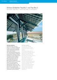
Top Sky Vordächer<br />
Vordächer bieten nicht nur<br />
Schutz vor schlechter Witterung,<br />
sondern sind auch ein gestalterisches<br />
Produkt für Eingangsbereiche<br />
oder Fassaden.<br />
Die Vordachkonstruktionen sind<br />
mit unterschiedlicher Verglasung<br />
kombinierbar. Mit klarem Sicherheitsglas<br />
als reinem Regenschutz,<br />
mit getöntem Glas als Regen-<br />
und Sonnenschutz, oder mit<br />
Photovoltaik-Elementen als<br />
gleichzeitige Energiequelle.<br />
Die Tragkonstruktion von Top Sky<br />
besteht aus hochwertigem,<br />
korrosionsbeständigem und<br />
pflegeleichtem Aluminium. Mit<br />
den attraktiven Trägerprofilen, die<br />
farblich frei gestaltet werden<br />
können, erhält jede Gebäudehülle<br />
interessante optische Akzente.<br />
Top Sky canopies<br />
Canopies offer weather<br />
protection and are a design<br />
product for entrance areas or<br />
façades.<br />
The canopy designs can be<br />
combined with different types of<br />
glazing: clear safety glass as<br />
protection against rain, with<br />
tinted glass as protection against<br />
both rain and sun, or with<br />
photovoltaic units as a<br />
simultaneous energy source.<br />
The Top Sky load-bearing<br />
structure consists of high quality,<br />
corrosion-resistant and easy-tomaintain<br />
aluminium. The<br />
attractive load-bearing profiles<br />
which can be painted in any<br />
colour endow any building<br />
envelope with a distinctive<br />
appearance.
Vordachkonstruktion Top Sky 1<br />
Schüco Top Sky 1 Vordächer<br />
haben eine feste Dachneigung<br />
von 30°. Durch die Dachneigung<br />
hat das Vordach einen hohen<br />
Selbstreinigungsgrad.<br />
Es sind Rasterbreiten von<br />
600 mm bis 1500 mm mit einer<br />
Ausladung von 1260 mm bis<br />
1470 mm je nach statischen<br />
Erfordernissen möglich.<br />
Top Sky 1 canopy construction<br />
Schüco Top Sky 1 canopies have<br />
a fixed roof slope of 30°. The roof<br />
slope means that the canopy has<br />
excellent self-cleaning properties.<br />
Module widths of between 600<br />
and 1500 mm with a projection<br />
of 1260 to 1470 mm are possible,<br />
depending on structural<br />
requirements.<br />
Vordachkonstruktion Top Sky 2<br />
Mit Top Sky 2 kann die Dachneigung<br />
variabel zwischen 30° und<br />
45° mit starrem Firstanschluss<br />
und 10° bis 45° mit gelenkig ausgeführem<br />
Firstanschluss gewählt<br />
werden. Es sind Rasterbreiten<br />
von 600 mm bis 1500 mm mit<br />
einer Ausladung von 1310 mm<br />
bis 2060 mm je nach statischen<br />
Erfordernissen möglich.<br />
Top Sky 2 canopy construction<br />
Top Sky 2 allows the roof slope<br />
to be varied between 30° and<br />
45° with fixed ridge attachment<br />
and 10° to 45° with pinned ridge<br />
connection. Module widths of<br />
between 600 and 1500 mm with<br />
a projection of 1310 to 2060 mm<br />
are possible, depending on<br />
structural requirements.<br />
Top Sky 1<br />
Aluminiumkonsole als Tragprofil mit feststehendem<br />
Neigungswinkel von 30°<br />
Aluminium brackets as load-bearing profile with fixed<br />
angle of inclination of 30°<br />
Top Sky 2<br />
Aluminium Tragprofil mit Gelenkarm für einen<br />
variablen Neigungswinkel von 10° bis 45°<br />
Aluminium load-bearing profile with adjustable<br />
bracket for an angle of inclination varying between<br />
10° and 45°<br />
Weiteres Zubehör<br />
Additional accessories<br />
Ansichtsbreite: 50 mm<br />
Face width: 50 mm<br />
Höhe Andruckprofil: 8 mm<br />
Height of pressure plate: 8 mm<br />
Verglasungsdicke: 8 - 16 mm<br />
Glazing thickness: 8 - 16 mm<br />
Bautiefe Tragprofil: 45 mm<br />
Basic depth of load-bearing profile: 45 mm<br />
Ansichtsbreite: 50 mm<br />
Face width: 50 mm<br />
Höhe Andruckprofil: 14 mm<br />
Height of pressure plate: 14 mm<br />
Verglasungsdicke: 8 - 16 mm<br />
Glazing thickness: 8 - 16 mm<br />
Bautiefe Tragprofil: 28 mm<br />
Basic depth of load-bearing profile: 28 mm<br />
Maßstab 1:4<br />
Scale 1:4<br />
Schüco | 111<br />
Basic systems<br />
Basissysteme
112 | Schüco<br />
Weiteres Zubehör<br />
Additional accessories<br />
Fassadenanbindungen<br />
Façade attachments<br />
Befestigungsmittel<br />
Schüco bietet für viele Fassadenanbindungen<br />
mit entsprechenden<br />
Befestigungseinheiten Systemlösungen<br />
an.<br />
Befestigungseinheiten für<br />
Vordächer<br />
Mit dieser Befestigungseinheit<br />
lassen sich die Vordachkonstruktionen<br />
Top Sky 1 und Top Sky 2<br />
an die Fassade anschließen.<br />
FV<br />
Befestigungseinheit für<br />
Sonnenschutzsysteme<br />
Befestigungseinheit aus Edelstahl-A4<br />
für den Anschluss von<br />
Sonnenschutzanlagen an die<br />
Fassade.<br />
Fixing assembly for solar<br />
shading systems<br />
A4 stainless steel fi xing unit, for<br />
attaching solar shading to the<br />
façade.<br />
Fixings<br />
Schüco offers system solutions<br />
for many façade attachments<br />
with corresponding fi xing<br />
assemblies.<br />
Fixing units for canopies<br />
This fi xing unit can be used to<br />
attach the Top Sky 1 and Top<br />
Sky 2 canopy designs to the<br />
façade.<br />
FV [kN]<br />
1300<br />
1200<br />
1100<br />
1000<br />
900<br />
800<br />
700<br />
600<br />
500<br />
40 50 60 70 80 90<br />
F V [kN] Maximale Gebrauchskraft<br />
Maximum force<br />
L Lastabstand<br />
Loading gap<br />
F V = [kN]<br />
55<br />
L [mm]<br />
Maßstab 1:2<br />
Scale 1:2<br />
100 L
Schwertanbindung<br />
aus Aluminium, für den Anschluss<br />
von weiteren Bauteilen<br />
mit großen Lastabtragungen wie<br />
zum Beispiel Sonnenschutzlamellen<br />
des Systems Schüco ALB,<br />
Reklameschilder oder Wartungsbalkone<br />
an die Fassade.<br />
F V [kN]<br />
12<br />
10<br />
8<br />
6<br />
100<br />
F V [kN] Maximale Gebrauchskraft<br />
Maximum force<br />
L Lastabstand<br />
Loading gap<br />
Gerüstverankerung<br />
bestehend aus einer Ringschraube<br />
und einem Grundprofil mit<br />
Schrauben zur einfachen Montage<br />
und Demontage eines Gerüstes.<br />
Die Grundprofile für die<br />
Verankerungspunkte verbleiben<br />
in den Pfostenprofilen, sodass<br />
ein sicherer Wiederaufbau des<br />
Gerüstes zu eventuellen<br />
Reparaturarbeiten möglich ist.<br />
Die Traglast, nach DIN 4420<br />
(Traglastversuche an Gerüstverankerungen),<br />
wird erreicht.<br />
Bracket attachment<br />
Aluminium, for fixing additional<br />
building components with high<br />
load transfers, e.g. Schüco ALB<br />
sunblinds, advertising signs,<br />
maintenance cradles,<br />
etc. to the façade.<br />
150 200 L<br />
F V = [kN]<br />
1420<br />
L [mm]<br />
Frame anchor<br />
consisting of a ring bolt and a<br />
base profile with screws for easy<br />
installation and de-installation of<br />
a frame. The base profiles for the<br />
anchorage points remain in the<br />
mullion profiles, allowing the<br />
frame to be rebuilt safely should<br />
any repairs be needed.<br />
The ultimate load, in accordance<br />
with DIN 4420 (load trials on<br />
frame anchors) is met.<br />
26<br />
Weiteres Zubehör<br />
Additional accessories<br />
FV<br />
50<br />
Maßstab 1:4<br />
Scale 1:4<br />
Schüco | 113<br />
Basic systems<br />
Basissysteme
114 | Schüco<br />
Weiteres Zubehör<br />
Additional accessories<br />
Schüco Brüstungssicherung<br />
Schüco safety bars<br />
Glass and stainless steel safety<br />
barriers<br />
Floor-to-ceiling units can be an<br />
important part of building design<br />
and ensure a high level of light<br />
penetration. Separating the units<br />
through the use of spandrel<br />
transoms may often spoil the<br />
appearance of a building. Glass<br />
or stainless steel safety barriers<br />
are an attractive alternative which<br />
can be incorporated into the<br />
design of the building. However,<br />
these are often expensive,<br />
project-specific solutions for<br />
which individual structural<br />
calculations are required.<br />
Schüco however, is able to offer a<br />
system solution: Schüco glass or<br />
stainless steel safety barriers<br />
represent complete systems<br />
offering tried-and-tested quality<br />
for different applications. They<br />
consist of perfectly tailored<br />
system components available<br />
from stock, including fixing<br />
accessories. Preliminary<br />
structural calculations are<br />
available for these systems.<br />
Brüstungssicherung aus Glas<br />
und Edelstahl<br />
Geschosshohe Elemente können<br />
ein wichtiges gestalterisches<br />
Element eines Gebäudes sein und<br />
sorgen für einen hohen Lichteinfall.<br />
Eine Teilung der Elemente<br />
durch Brüstungsriegel wirkt dabei<br />
oft störende und optisch nicht<br />
ansprechend. Eine Brüstungssicherung<br />
aus Glas oder Edelstahl<br />
ist dabei eine formschöne<br />
Alternative, die sogar als Designelement<br />
Akzente setzen kann.<br />
Allerdings sind dies oft objektbezogene,<br />
recht aufwändige<br />
Lösungen, welche für jeden<br />
Einzelfall statisch zu ermitteln<br />
sind. Schüco bietet auch hier eine<br />
Systemlösung. Die Schüco<br />
Brüstungssicherungen aus Glas<br />
oder Edelstahl sind komplette<br />
Systeme für unterschiedliche<br />
Anwendungen in systemgeprüfter<br />
Qualität. Sie bestehen aus<br />
lagermäßig vorhandenen,<br />
aufeinander abgestimmten<br />
Systemkomponenten, inklusive<br />
Befestigungszubehör. Für diese<br />
Systeme stehen Angaben zur<br />
statischen Vordimensionierung<br />
zur Verfügung.
Statische Vorbemessung<br />
Bei Einsatz der Brüstungsverglasung<br />
sowie der Edelstahl-<br />
Horizontalstäbe als absturzsicherndes<br />
Bauteil sind für Planung<br />
und Dimensionierung alle<br />
gültigen Vorschriften der geltenden<br />
Landesbauordnung, der ETB<br />
Richtlinien, TRLV und Arbeitsstätten-Richtlinien<br />
zu beachten.<br />
Preliminary structural analysis<br />
When using spandrel glazing and<br />
stainless steel horizontal bars as<br />
safety barriers, the regulations of<br />
the local building authority, ETB<br />
guidelines, TRLV and workshop<br />
guidelines must be observed<br />
during the planning and<br />
designing stages.<br />
Brüstungsverglasung<br />
• Vollkommen transparente<br />
Absturzsicherung mit VSG-<br />
Scheibe nach TRAV (Kategorie<br />
A) und Bauregelliste<br />
• Optisch dezente Anwendung<br />
durch Befestigung der Halter<br />
am Blendrahmen<br />
• Einsetzbar bei Einsatzelementen<br />
der Standard- und<br />
Block-Fensterserien<br />
• Prädestiniert bei bodentiefen<br />
Einsatzelementen<br />
• Kantenschutz der oberen freien<br />
Glaskante bauseits<br />
• Allgemeines bauaufsichtliches<br />
Prüfzeugnis (Prüfzeugnis-Nr.<br />
8593)<br />
• Glasdicken von 10 - 16 mm<br />
einsetzbar<br />
Maximale Abmessungen beim Einsatz der Brüstungsverglasung als Brüstungssicherung<br />
Maximum dimensions when using spandrel glazing as safety barriers<br />
Abmaße * / Dimensions * Werte in mm / Values in mm<br />
Maximale Glasbreite<br />
Maximum glass width<br />
Maximale Höhe<br />
Maximum height<br />
Glasscheibendicke<br />
Glass pane thickness<br />
1500 mm<br />
900 - 1100 mm<br />
Landesbauordnung (LBO) beachten<br />
Observe local building regulations (LBO)<br />
10 - 16 mm<br />
mindestens 2 x 5 mm VSG aus ESG mit 0,76 mm<br />
Foliendicke **<br />
Minimum of 2 x 5 mm LSG made of TSG with 0.76 mm<br />
foil thickness **<br />
* Abmessungen gemäß Allgemein bauaufsichtlichen Prüfzeugnis 02/2007 für Absturzsichernde Verglasungen<br />
TRAV. Prüfzeugnis für Stoßfestigkeit 8593<br />
Dimensions in accordance with General Building Approval Test Certificate 02/2007<br />
for safety barrier glazing (TRAV). Test certificate for impact resistance 8593<br />
** Eine Glasdickendimensionierung und ein statischer Nachweis sind objektbezogen durchzuführen.<br />
Glass thickness and structural calculations must be carried out for each project.<br />
Weiteres Zubehör<br />
Additional accessories<br />
Spandrel glazing<br />
• Completely transparent safety<br />
barriers with laminated safety<br />
glass in accordance with TRAV<br />
(category A) and the German<br />
Building Regulations List<br />
• Discreet appearance as the<br />
brackets are fixed to the outer<br />
frame<br />
• For use in insert units in the<br />
standard and block window<br />
series.<br />
• Ideal for floor-to-ceiling insert<br />
units<br />
• Edge protection for the top<br />
open glass edge supplied by<br />
the customer<br />
• General Building Approval Test<br />
Certificate (test certificate no.<br />
8593)<br />
• Glass thicknesses of<br />
10 - 16 mm can be used<br />
Schüco | 115<br />
Basic systems<br />
Basissysteme
116 | Schüco Weiteres Zubehör<br />
Additional accessories<br />
Brüstungssicherung aus<br />
Edelstahl<br />
• Systemgeprüfte Lösung – ab<br />
Lager lieferbar<br />
• Sichere Befestigungstechnik<br />
zwischen Blendrahmen und<br />
Edelstahladapter<br />
• Inklusive Angaben zur statischen<br />
Vordimensionierung<br />
• Auch als optisches Gestaltungselement<br />
für Fenster,<br />
Türen und Fassaden einsetzbar<br />
um architektonische Akzente<br />
zu setzen<br />
Maximale Spannweite in Abhängigkeit der horizontalen Last<br />
Maximum span width depending on horizontal load<br />
Durchmesser Rundstab<br />
Round bar diameter<br />
Maximale Spannweite / Maximum span width<br />
Horizontale Last * / Horizontal load *<br />
q = 0,5 kN/m q = 1,0 kN/m<br />
ø 8 mm 350 mm 250 mm<br />
ø 12 mm 660 mm 460 mm<br />
ø 20 mm 1350 mm 1000 mm<br />
ø 30 mm 2250 mm 1850 mm<br />
* Horizontale Last<br />
für den privaten Wohnungsbau:<br />
q = 0,5 kN/m<br />
für die Anwendung in öffentlichen Gebäuden:<br />
q = 1,0 kN/m<br />
es gelten Tabellenwerte nach DIN 1055<br />
Stainless steel safety barriers<br />
• System-tested solution –<br />
supplied ex stock<br />
• Secure fixing technology<br />
between outer frame and<br />
stainless steel adapter<br />
• Includes details on preliminary<br />
structural calculations<br />
•<br />
Can also be used as an<br />
attractive design feature for<br />
windows, doors and façades to<br />
add architectural expression<br />
* Horizontal load<br />
for private housing:<br />
q = 0,5 kN/m<br />
for use in public buildings:<br />
q = 1,0 kN/m<br />
table values in accordance with DIN 1055<br />
Hinweis:<br />
Größere Stützweiten und<br />
kleinere Stabdurchmesser beim<br />
Einsatz als rein optisches<br />
Gestaltungselement möglich.<br />
Note:<br />
Larger span widths and smaller<br />
bar diameters are possible if the<br />
bars are being used solely for<br />
decorative purposes.
Leitungsführung und Blitzschutz<br />
Cabling and lightning protection<br />
e-connect<br />
• Intelligente Systemlösung zur<br />
verdeckten Leitungsführung in<br />
der Fassade<br />
• Anschluss elektrischer Komponenten<br />
in der Fassade<br />
• Einfache, sichere und<br />
rationelle Verlegung elektrischer<br />
Leitungen in der<br />
Fassade<br />
• Verdeckt liegende Führung<br />
elektrischer Leitungen durch<br />
entsprechend konzipierte<br />
Profile<br />
• Leitungsdurchführung von<br />
innen nach außen und innerhalb<br />
der Profile<br />
• Starre Leitungsfixierung<br />
oder demontierbare<br />
Leitungsverlegung<br />
Blitzschutz<br />
Verdeckt liegende Integration<br />
der Blitzableitungsvorrichtung<br />
in die Fassadensysteme<br />
SMC 50 und FW 50 + /FW 60 +<br />
•<br />
• Systemlösung geprüft nach<br />
DIN EN 50164<br />
• Eindeutige Schnittstelle<br />
zwischen den Gewerken<br />
(<strong>Metallbau</strong>er und<br />
Blitzschutzbauer)<br />
• Hohe Verarbeitungs- und<br />
Planungssicherheit durch<br />
geprüfte und detailliert<br />
dokumentierte Systemlösung<br />
Weiteres Zubehör<br />
Additional accessories<br />
e-connect<br />
• Intelligent system solution for<br />
concealed cabling in the façade<br />
• Connection of electrical<br />
components in the façade<br />
• Simple, secure and efficient<br />
electrical wiring within the<br />
façade<br />
• Concealed electrical wiring<br />
through specially designed<br />
profiles<br />
• Wiring from inside to outside<br />
and also within the profiles<br />
• Static cable fixing or<br />
detachable cable laying<br />
Lightning protection<br />
Concealed integration of<br />
lightning conduction device in<br />
the SMC 50 and FW 50 + /<br />
FW 60 + •<br />
façade systems<br />
• System solution tested in<br />
accordance with DIN EN 50164<br />
• Clear interface between trades<br />
(metal fabricator and<br />
constructor of lightning<br />
protection)<br />
• High fabrication and planning<br />
reliability as this is a tested<br />
system solution with detailed<br />
documentation<br />
Schüco | 117<br />
Basic systems<br />
Basissysteme