

ICOM JTG SYSTEM GENERAL SCHEME
ICOM JTG SYSTEM GENERAL SCHEME
ICOM JTG SYSTEM GENERAL SCHEME

Create successful ePaper yourself
Turn your PDF publications into a flip-book with our unique Google optimized e-Paper software.
icom S.p.A.<br />
Icom Jtg ® System<br />
Assembling instructions, setting and<br />
calibration<br />
11.2 Pump power supply check<br />
Page 26 of 27<br />
An excessive current measured on the pump power supply circuit will be a “signal”<br />
of a bad functioning of the <strong>JTG</strong> System .<br />
It will be very important to measure power supply for the pump/system as per the<br />
instruction above.<br />
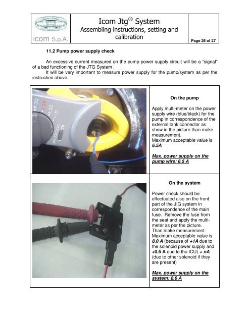
On the pump<br />
Apply multi-meter on the power<br />
supply wire (blue/black) for the<br />
pump in correspondence of the<br />
external tank connector as<br />
show in the picture than make<br />
measurement.<br />
Maximum acceptable value is<br />
6.5A<br />
Max. power supply on the<br />
pump wire: 6.5 A<br />
On the system<br />
Power check should be<br />
effectuated also on the front<br />
part of the JIG system in<br />
correspondence of the main<br />
fuse. Remove the fuse from<br />
the seat and apply the multi-<br />
meter as per the picture.<br />
Than make measurement.<br />
Maximum acceptable value is<br />
8.0 A (because of +1A due to<br />
the solenoid power supply and<br />
+0.5 A due to the ICU) + nA<br />
(due to other solenoid if they<br />
are present)<br />
Max. power supply on the<br />
system: 8.0 A