

PDF, 668 KB - QTronic
PDF, 668 KB - QTronic
PDF, 668 KB - QTronic

Create successful ePaper yourself
Turn your PDF publications into a flip-book with our unique Google optimized e-Paper software.
presented at: 8th International Modelica Conference, 20-22.03.2011, Dresden, Germany<br />
Simulation-based development of<br />
automotive control software with Modelica<br />
Emmanuel Chrisofakis 1 , Andreas Junghanns 2 , Christian Kehrer 3 , Anton Rink 1<br />
1 Daimler AG, 70546 Stuttgart<br />
2 <strong>QTronic</strong> GmbH, Alt-Moabit 91a, 10559 Berlin<br />
3 ITI GmbH, Webergasse 1, 01067 Dresden<br />
{emmanuel.chrisofakis, anton.rink}@daimler.com, andreas.junghanns@qtronic.de, kehrer@iti.de<br />
Abstract<br />
We present and discuss the Modelica-based development<br />
environment currently used by Daimler to develop<br />
powertrain control software for passenger cars.<br />
Besides well calibrated vehicle models, the environment<br />
supports automotive standards such as A2L,<br />
MDF, CAN, and XCP to integrate control software<br />
and simulated vehicles on Windows PCs.<br />
Keywords: automotive software development, software<br />
in the loop<br />
1 Introduction<br />
More and more automotive functions are implemented<br />
using software. Hence, there is an increasing demand<br />
to support the corresponding development process<br />
using virtual, i. e. simulation-based development<br />
environments.<br />
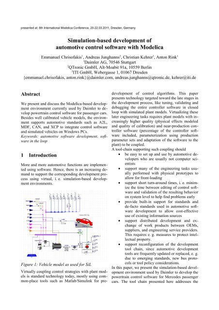
Figure 1: Vehicle model as used for SiL<br />
Virtually coupling control strategies with plant models<br />
is standard technology today, mostly using common-place<br />
tools such as Matlab/Simulink for pre-<br />
development of control algorithms. This paper<br />
presents technology targeted toward the late stages in<br />
the development process, like tuning, validating and<br />
debugging the entire controller software in closed<br />
loop with simulated plant models. Virtualizing these<br />
later engineering tasks requires plant models with increasingly<br />
higher quality (physical effects modeled<br />
and quality of calibration) and near-production controller<br />
software (percentage of the controller software<br />
included, parameterization using production<br />
parameter sets and adaptation of the software to the<br />
plant) to be coupled.<br />
A tool-chain supporting such coupling should<br />
• be easy to set up and use by automotive developers<br />
who are usually not computer scientists<br />
• support many of the engineering tasks usually<br />
performed with physical prototypes to<br />
allow for front-loading<br />
• support short turn-around times, i. e. minimize<br />
the time between editing of control software<br />
and validation of the resulting behavior<br />
on system level to help find problems early<br />
• provide built-in support for standards and<br />
de-facto standards used in automotive software<br />
development to allow cost-effective<br />
use of existing information sources<br />
• support distributed development and exchange<br />
of work products between OEMs,<br />
suppliers, and engineering service providers.<br />
This requires e. g. measures to protect intellectual<br />
property.<br />
• support reconfiguration of the development<br />
tool chain, since automotive development<br />
tools are frequently updated or replaced, e. g.<br />
due to emerging standards, new bus protocols<br />
or tool policy considerations.<br />
In this paper, we present the simulation-based development<br />
environment used by Daimler to develop the<br />
powertrain control software for Mercedes passenger<br />
cars. The tool chain presented here addresses the
above demands. It is based on vehicle models implemented<br />
using Modelica and processed using SimulationX<br />
as a tool for the design and analysis of complex<br />
systems, the FMU standard for model exchange,<br />
MATLAB/Simulink and TargetLink as a tool for<br />
model based development of automotive controllers<br />
and Silver as a tool for virtual integration of control<br />
software, application data and the simulated vehicle.<br />
The paper is structured as follows: In the next section,<br />
we describe why and how Modelica is used<br />
here to create vehicle models. Section 3 describes<br />
how such a vehicle model is then coupled with control<br />
software and what else is needed to get automotive<br />
control software running in closed loop on a PC.<br />
Section 4 describes how such a SiL setup is used to<br />
support automotive software development, and section<br />
5 describes costs and benefits of setting up a<br />
SiL.<br />
2 Vehicle models<br />
Daimler started around 2004 to use Modelica for<br />
building vehicle models used for test and development<br />
of powertrain control software via software in<br />
the loop (SiL). For example, the members of the 7G-<br />
Tronic transmission family have been developed this<br />
way [1]. Ongoing projects developed within this<br />
Modelica-based framework include dual-clutch<br />
transmissions by Mercedes [2] and AMG [3], and<br />
hybrid drivetrains. Basic requirement of a plant model<br />
in a SiL-environment for automatic gearboxes is<br />
the accurate calculation of the gear shifting. In order<br />
to achieve this goal, detailed model representation of<br />
gearbox kinematics, clutch mechanics and hydraulic<br />
control is essential. Therefore special Modelica libraries<br />
have been developed over the years to support<br />
transmission development.<br />
For the development of customer specific libraries<br />
SimulationX offers a wealth of options such as the<br />
dedicated TypeDesigner that simplifies graphical and<br />
textual modeling compared to traditional forms.<br />
Based on these libraries, a well calibrated vehicle<br />
model for a new transmission project can be setup<br />
within just a few weeks. This short development is<br />
partly credited to good properties of the Modelica<br />
language, which provides outstanding support for the<br />
reuse of component models, mainly by providing<br />
powerful means to parametrize models and built-in<br />
support for acausal modeling. Latter feature offers<br />
the model developer great possibilities to calibrate<br />
and validate his model by using measurements either<br />
from car or from test rig since no model modifica-<br />
tions are necessary if the measured signal is a flow or<br />
potential quantity (e. g. torque as opposed to speed).<br />
Figure 2: Gearset of a 7G-Tronic Transmission<br />
Different capabilities for implementing measured<br />
data in SimulationX and validating the Modelica<br />
models against these data without the necessity of<br />
using another tool in combination with further options<br />
like the VariantsWizard help to increase the effiency<br />
of model calibration. With special regard to<br />
the needs of powertrain modeling ITI provides different<br />
analyzing methods, e. g. the linear system analysis<br />
or the steady state simulation.<br />
Figure 3: Transmission hydraulics<br />
Figures 1, 2 and 3 show typical Modelica models<br />
used in series development projects.<br />
Daimler uses Dymola and also SimulationX [4] to<br />
edit and process Modelica models. Since Modelica<br />
version 3.1 there is full compatibility of the plant<br />
models both in Dymola 7.4 as well as in Simula-
Figure 4: Modelica library Car in SimulationX and Dymola<br />
tionX 3.4. Models and libraries are stored on hard<br />
disk as .mo files. Both tools are able to read these<br />
files with no specific modification, i. e. they use exactly<br />
the same files for displaying exactly the same<br />
structure. Figure 4 shows a screenshot of the directory<br />
structure and the integration in every tool.<br />
This proves that one design goal of Modelica and the<br />
Modelica Standard Library (MSL) has been reached<br />
now, namely to provide a tool-vendor independent<br />
representation format for simulation models. There<br />
are however still a few issues to be solved to fully<br />
reach vendor independence of the MSL:<br />
• The definition of tables in Modelica Standard<br />
Library is based on external functions.<br />
The implementation of these functions is not<br />
part of the library itself and has to be done<br />
by tool vendors. In consequence of missing<br />
specification the different implementations<br />
are not completely compatible.<br />
• With the exclusive usage of external functions<br />
it is difficult to adapt the implementation<br />
on the requirements of the underlying<br />
tool. The substitution of external functions<br />
by external objects would improve the implementation<br />
capabilities.<br />
• For users of a Modelica tool it is difficult to<br />
decide whether a used construct is compatible<br />
to Modelica language specification or<br />
not (e. g. classDirectory function). All tool<br />
dependent extensions of Modelica language<br />
should be marked as vendor specific similar<br />
to existing vendor specific annotations.<br />
• Modelica libraries often use different version<br />
of annotations for graphical objects or attributes<br />
which are invalid in the particular context<br />
(e.g. fillColor for lines). While several<br />
tools ignore such annotations other programs<br />
generate error messages, which can be a<br />
little bit confusing for users and developers.<br />
For that reason a stronger validation of annotations<br />
would be preferable.<br />
To create a Software in the Loop setup, the Modelica<br />
model is then exported. In previous years, the C code<br />
generated by either Dymola or SimulationX from a<br />
given Modelica model has been wrapped and compiled<br />
for execution by one of the SiL tools described<br />
in Section 3. For export, special wrapper code had to<br />
be developed for each simulation tool, and even for<br />
each version of such a tool, which was time consuming<br />
and error prone. Daimler started recently to use<br />
the FMI [8] developed within the Modelisar project<br />
as an export format for Modelica models. This standard<br />
is supported by the latest versions of SimulationX,<br />
Dymola, and Silver. This removes the need to<br />
maintain version and vendor specific wrapper code,<br />
which further improves and speeds up the SiL-based<br />
development process.<br />
3 Getting automotive control software<br />
into the loop<br />
Daimler uses Silver [5] and its in-house predecessor<br />
Backbone to virtually integrate vehicle models and<br />
control software on Windows PCs. Tools such as Silver<br />
or Backbone are mainly needed to support vari
Figure 5: SiL environment an its interfaces to automotive standards<br />
ous standards and quasi-standards used for automotive<br />
software development. Developers are familiar<br />
with these standards and know how to use them.<br />
Data is available in these formats already as part of<br />
the existing tool chain and reuse is virtually free of<br />
cost. Furthermore, using these data sources in the<br />
virtual development process allows early validation<br />
of these data sources. A virtual development environment<br />
should therefore mimic, emulate, or else how<br />
support these standards. A few examples of how the<br />
SiL tool supports automotive standards is shown in<br />
Fig. 5.<br />
Developers typically use tools such as CANape<br />
(Vector) or INCA (ETAS) to measure signals and<br />
calibrate (fine-tune) parameters of the control software<br />
in the running car or on a test rig using standard<br />
protocols such as CCP or XCP. The SiL environment<br />
implements this protocol. Seen from a measurement<br />
tool such as CANape, a SiL simulation behaves just<br />
like a real car. Developers can therefore attach his favorite<br />
measurement tool to the SiL to measure and<br />
calibrate using the same measurement masks, data<br />
sources and procedures they are using in a real car.<br />
Likewise, automotive developers use MDF files to<br />
store measurements. The SiL can load and save this<br />
file format. A measured MDF file can e. g. be used<br />
to drive a SiL simulation.<br />
Another example is A2L. This is a database format<br />
used to store key information about variables and<br />
(tunable) parameters of automotive control software.<br />
A2L contains e. g. the address of variables in the<br />
ECU, its physical unit, comment and scaling information<br />
that tells how to convert the raw integer value<br />
to a physical value. The SiL-environment reads A2L<br />
files and uses the information to automate many<br />
tasks, such as scaling of the integer variables of the<br />
control software to match the physical variables of<br />
the vehicle model.<br />
The SiL-environment also knows how to read DBC<br />
files. These describe how the control software communicates<br />
with other controllers using the CAN protocol.<br />
The SiL-environment uses this e. g. to implement<br />
rapid prototyping: Load the control software<br />
and the DBC into the SiL tool on your laptop, connect<br />
the laptop to car using a CAN card, and switch<br />
the ECU to 'remote control' mode. The control software<br />
running in the SiL tool controls then the corresponding<br />
system of the real car, e.g. an automatic<br />
transmission. The main advantage of such a setup is,<br />
that it saves time. Getting the control software running<br />
in a real ECU is typically much more time consuming<br />
than using a SiL tool or any other tool for<br />
rapid prototyping.<br />
Finally, the SiL tool can process PAR and HEX files.<br />
These files may contain calibration data, i. e. values<br />
for all the tunable parameters of the control software.<br />
The SiL tool knows how to load these values into the<br />
control software running in the SiL, emulating<br />
thereby the 'flash' process of the real ECU. In effect,<br />
the SiL tool is actually not only running the control<br />
software, but the fine-tuned version of the software,<br />
which enables much more detailed investigation and<br />
testing of the control software's performance.
Having all these standards available in the SiL eases<br />
the task of actually getting automotive control software<br />
running on a PC, and doing useful things with<br />
the resulting setup. Control software is typically decomposed<br />
into a number of so-called tasks (i. e.<br />
functions implemented in C) that are run by an<br />
RTOS (real-time operating system) such as OSEK.<br />
Many tasks are periodically executed with a fixed<br />
rate, e. g. every 10 ms. To get such tasks running in<br />
SiL, the user has to build an adapter as shown in<br />
Fig. 5, i. e. a little C program that implements the<br />
Silver module API and emulates the RTOS by calling<br />
each task once at every (or every 2nd, 3rd, ...)<br />
SiL macro step. The SiL tool is shipped with the<br />
SBS (Silver Basis Software), i. e. C sources that<br />
make it easy to build such an adapter by adapting<br />
template adapter code. A cheap alternative to writing<br />
an adapter is to use the SiL tool's support for MAT-<br />
LAB/Simulink and Realtime Workshop (RTW).<br />
Automotive software is often developed by first creating<br />
a model of the controller using Simulink. The<br />
model is then used to automatically generate fixpoint<br />
integer code, e. g. using tools like the Embedded<br />
Coder from MathWorks, TargetLink from<br />
dSPACE, or Ascet from ETAS (model-based development).<br />
The SiL tool contains support for exporting<br />
a Simulink model using RTW. The result will not<br />
use fix-point integer but floating point arithmetic, so<br />
it is Model-in-the-loop (MiL), as opposed to Software-in-the-loop<br />
(SiL). This is a fast push button<br />
solution for exporting a controller model to SiL,<br />
which does not require any hand coding, and is<br />
therefore attractive.<br />
Figure 6: Software in the Loop (SiL) setup of<br />
transmission control software and vehicle model<br />
4 Using the system model during<br />
automotive development<br />
So far we have mainly described what is needed to<br />
get automotive control software running on a Windows<br />
PC, in a closed loop with the simulated<br />
vehicle. This section describes how such a SiL setup<br />
can then be used to support the development process.<br />
Supported activities include<br />
• Virtual integration: Automotive control software<br />
for a single ECU typically consists of<br />
dozens of software modules, developed independently<br />
by a team of developers. Having a<br />
SiL helps to detect problems in the interplay<br />
of these modules early, long before an attempt<br />
is made to run all the module in a real<br />
car. For example, before releasing a new<br />
version of his module, a developer can<br />
quickly check on his PC whether the module<br />
works together with the modules of other developers.<br />
To do this, he only needs access to<br />
compiled modules (object files), not to the<br />
sources of other modules [2]. An additional<br />
benefit here is the isolation of developers<br />
from the changes of others when validating<br />
their modifications early on as his changes<br />
are only local to his own sources. Later integration<br />
efforts build on modifications<br />
already validated, albeit in isolation.<br />
• Debugging: In contrast to the situation in a<br />
real car or on a HiL test rig, simulation can<br />
be halted in SiL. It is then possible to inspect<br />
all variables, or to change certain values to<br />
simulate a fault event. In conjunction with a<br />
debugger (such as Microsoft Visual Studio),<br />
it is even possible to set breakpoints or to<br />
single-step through the controller code,<br />
while staying in closed loop with the simulated<br />
car. The SiL tool can also be used to<br />
debug problems measured in a real car, if a<br />
measurement file (MDF) is available. In this<br />
case, simulation is driven by the measurement,<br />
and the SiL complements this measurement<br />
by computing the missing signals to<br />
provide a full picture needed to debug the<br />
problem.<br />
• Fault simulation: Using a SiL, it is possible<br />
to create and explore scenarios that would be<br />
difficult or impossible to realize in a real car<br />
or on a test rig. For example, you can simulate<br />
strong wind [7] or inject arbitrary component<br />
faults into the simulation.<br />
• Comparing versions: The SiL tool offers a<br />
function to compare the behavior of different
software versions by comparing all signals<br />
computed by these versions. This is e. g.<br />
useful when checking for equivalence after<br />
refactoring or clean up of modules.<br />
• Scripting: A SiL simulation can be driven by<br />
a script, written e. g. in Python. This can be<br />
used to implement optimization procedures,<br />
for performing tests, or to trigger self-learning<br />
algorithms that adapt the control software<br />
to certain properties of the (simulated)<br />
car, e. g. to compensate aging of components.<br />
• Systematic testing: In conjunction with the<br />
test case generator TestWeaver, the SiL tool<br />
allows the systematic testing of control software.<br />
TestWeaver generates thousands of<br />
test cases which are then executed by the SiL<br />
tool.<br />
• Virtual endurance testing: calculation of<br />
load collectives for gearbox and drivetrain,<br />
e. g. to develop and test measures for safeguarding<br />
of the drivetrain components.<br />
• Application/Calibration: of the control software<br />
on the PC.<br />
Figure 7: A debugger attached to Silver<br />
A typical use case of the SiL tool is shown in Fig. 7.<br />
The test case generator TestWeaver [8] has found a<br />
scenario where the control software of a transmission<br />
performs a division by zero. This is clearly a bug.<br />
The user replays the recorded scenario, with Microsoft<br />
Visual Studio attached to the SiL tool. When<br />
the division by zero occurs, the debugger pops up as<br />
shown in the figure, showing the line in the controller<br />
source code that causes the exception.<br />
5 Costs and benefits<br />
Main cost factors of using the simulation-based tool<br />
chain for automotive software development are<br />
• development and maintenance of the simulation<br />
model: Here is where modern modeling<br />
languages and tools such as Modelica and<br />
SimulationX help reduce costs by reuse of<br />
components and easy parameterization<br />
• continuous calibration efforts to keep such a<br />
model up to date with the plant simulated:<br />
SimulationX allows continuous enhancements<br />
based on existing models and libraries<br />
by replacing components and models of<br />
varying complexity throughout all development<br />
phases. Reusing models including all<br />
interfaces necessary for calibration in combination<br />
with a wide range of tool options,<br />
e. g. VariantsWizard, COM-scripting or optimization<br />
tools, leads to an increasing efficiency<br />
in the workflow.<br />
• Building the adapter code for the controller<br />
software: With the introduction of the Silver<br />
Basic Software package, this effort is significantly<br />
reduced.<br />
Despite continuing cost-reduction efforts, these investments<br />
are still significant.<br />
They are compensated by the benefits of such a Software<br />
in the Loop setup for developing control software,<br />
namely<br />
• extremely fast development cycles: due to<br />
comfortable integration of software and<br />
vehicle components on the PC of the developer.<br />
This helps to detect problems early.<br />
• excellent debugging and test support, e. g.<br />
with Microsoft Visual Studio Debugger or<br />
<strong>QTronic</strong> TestWeaver [1,2,3,6]. Found problems<br />
can be exactly reproduced as often as<br />
needed.<br />
• parallelize the development process: A SiL<br />
configuration can easily be duplicated at low<br />
cost. This way, every member of a team can<br />
use its personal 'virtual' development environment<br />
24 hours a day, without blocking<br />
rare resources like HiL test rigs, or physical<br />
prototypes.<br />
• sharing results without sharing IP: All members<br />
of a team exchange working results by<br />
exchanging compiled modules (DLLs), not<br />
sources. This helps to protect intellectual<br />
property.<br />
• executing others contributions without their<br />
tools: Our SiL runs modules (simulation<br />
models, control software) developed using
very different tools without accessing these<br />
tools. This greatly reduces the complexity of<br />
the SiL setups (no tool coupling).<br />
6 Conclusion<br />
We presented the tool chain used by Daimler for<br />
simulation-based development of transmission control<br />
software. The environment is based on Modelica,<br />
provides build-in support for automotive standards,<br />
imports vehicle models via the standard FMI<br />
and uses these models to perform closed-loop simulation<br />
of automotive control software. The virtual development<br />
environment created this way helps to<br />
shorten development cycles, eases test and debugging,<br />
helps to parallelize and hence to speed up development<br />
and provides a convenient platform for<br />
collaboration between Daimler's transmission development<br />
departments and its suppliers and engineering<br />
service providers.<br />
Acknowledgments<br />
Our work on the FMI [8] presented here has been<br />
funded by the Federal Ministry for Education and<br />
Science (BMBF) within the ITEA2 project MODEL-<br />
ISAR (Förderkennzeichen 01IS08002).<br />
References<br />
[1] A. Rink, E. Chrisofakis, M. Tatar: Automating<br />
Test of Control Software - Method for Automatic<br />
TestGeneration. ATZelektronik 6/2009<br />
Volume 4, pp. 24-27.<br />
[2] H. Brückmann, J. Strenkert, U. Keller, B. Wiesner,<br />
A. Junghanns: Model-based Development<br />
of a Dual-Clutch Transmission using Rapid<br />
Prototyping and SiL. International VDI Congress<br />
Transmissions in Vehicles 2009,<br />
Friedrichshafen, Germany, 30.06.-01-07.2009<br />
[3] M. Hart, R. Schaich, T. Breitinger, M. Tatar:<br />
Automated test of the AMG Speedshift DCT<br />
control software 9th International CTI Symposium<br />
Innovative Automotive Transmissions,<br />
Berlin, 30.11. - 01.12.2010, Berlin, Germany.<br />
[4] SimulationX, http://www.simulationx.com/<br />
[5] Silver, http://qtronic.de/en/silver.html<br />
[6] A. Junghanns, J. Mauss, M. Tatar: TestWeaver<br />
- A Tool for Simulation-based Test of Mechatronic<br />
Designs. 6th International Modelica Conference,<br />
Bielefeld, March 3 - 4, 2008, pp. 341 -<br />
348, 2008.<br />
[7] Hilf, Matheis, Mauss, Rauh: Automated Simulation<br />
of Scenarios to Guide the Development<br />
of a Crosswind Stabilization Function. 6th<br />
IFAC Symposium on Advances in Automotive<br />
Control, Munich, Germany, July 12 - 14, 2010.<br />
[8] FMI Specification 1.0, available for free from<br />
http://www.functional-mockup-interface.org/


