Processing Parameters Injection molding
Processing Parameters Injection molding
Processing Parameters Injection molding

You also want an ePaper? Increase the reach of your titles
YUMPU automatically turns print PDFs into web optimized ePapers that Google loves.
Machinery Design<br />
Machinery Design Machinery Design Machinery Design<br />
Machine Configurations<br />
<strong>Injection</strong> <strong>molding</strong> of IROGRAN® TPU can be conducted on most injection <strong>molding</strong><br />
machines. The main types used are:<br />
K1:<br />
These are standard injection <strong>molding</strong> machines with a single shot barrel<br />
injecting into a single or multi cavity mold. The weight of the injected part<br />
can be as high as several kilograms. Mold clamping forces range from a few<br />
tonnes to several thousand tonnes.<br />
K2:<br />
Is similar to K1 but uses two barrels and this permits the <strong>molding</strong> of several<br />
materials at the same time. Again, machine capacity can vary over a wide range.<br />
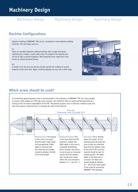
Which screw should be used?<br />
A conventional general purpose screw is recommended for the production of IROGRAN® TPU. It is also possible<br />
to process softer grades on a PVC type screw, however, care should be taken to avoid overheating during processing<br />
as this can lead to degradation of the TPU. The general purpose screw is split into 3 distinct zones and<br />
each zone plays an important part in changing the state of the material.<br />
Screw Tip<br />
Metering Zone: The purpose<br />
of this zone is to ensure<br />
that the melt is fully mixed<br />
and homogenised. Flight<br />
depth is constant here.<br />
The metering zone length<br />
should be between 30-40%<br />
of the total length.<br />
Ø 45 mm<br />
Compression ratio 1:2/Length 20 D<br />
Compression Zone: This<br />
is the zone where the TPU<br />
material is melted. The<br />
flight depth in this zone is<br />
constantly diminishing,<br />
which increases the pressure<br />
and ensures an increased<br />
contact with the cylinder<br />
wall. Compression ratios<br />
within this zone should be<br />
between 2.5 : 1 and 3.5 : 1.<br />
Feed Zone: This is directly<br />
below the hopper. As the<br />
material passes through this<br />
zone it picks up conducted<br />
heat from the cylinder walls.<br />
At the end of this zone the<br />
material should be near its<br />
softening point. The flight<br />
depth in the feed zone is<br />
constant. The feed zone<br />
should ideally be between<br />
30 – 40% of the total length<br />
of the screw for processing<br />
IROGRAN® TPU materials.<br />
| 2