

HELLRAISER SOLO 6 WIRING DIAGRAM - Schecter Guitars
HELLRAISER SOLO 6 WIRING DIAGRAM - Schecter Guitars
HELLRAISER SOLO 6 WIRING DIAGRAM - Schecter Guitars

Create successful ePaper yourself
Turn your PDF publications into a flip-book with our unique Google optimized e-Paper software.
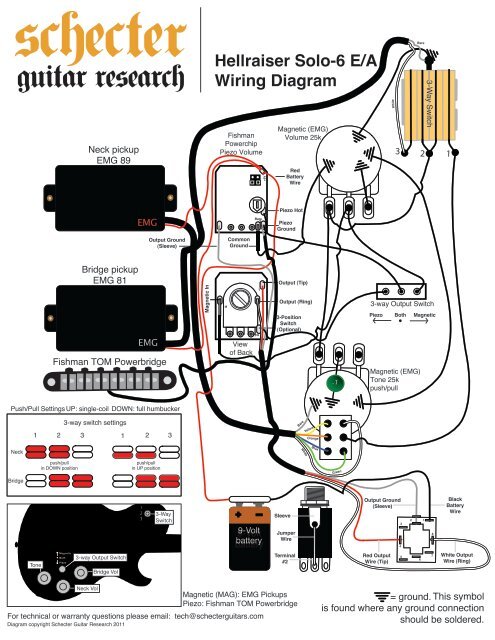
Neck pickup<br />
EMG 89<br />
Bridge pickup<br />
EMG 81<br />
Fishman TOM Powerbridge<br />
Output Ground<br />
(Sleeve)<br />
Push/Pull Settings UP: single-coil DOWN: full humbucker<br />
Neck<br />
Bridge<br />
1 2 3<br />
Tone<br />
push/pull<br />
in DOWN position<br />
3-way switch settings<br />
Magnetic<br />
Both<br />
Piezo<br />
3-way Output Switch<br />
Neck Vol<br />
Bridge Vol<br />
EMG<br />
EMG<br />
1 2 3<br />
push/pull<br />
in UP position<br />
1<br />
2<br />
3<br />
3-Way<br />
Switch<br />
Magnetic In<br />
Hellraiser Solo-6 E/A<br />
Wiring Diagram<br />
Fishman<br />
Powerchip<br />
Piezo Volume<br />
M<br />
Common<br />
Ground<br />
View<br />
of Back<br />
SW<br />
T<br />
+9V<br />
9-Volt<br />
battery<br />
Magnetic (EMG)<br />
Volume 25k<br />
Red<br />
Battery<br />
Wire<br />
Piezo Hot<br />
Piezo<br />
Ground<br />
Output (Tip)<br />
Output (Ring)<br />
3-Position<br />
Switch<br />
(Optional)<br />
Sleeve<br />
Jumper<br />
Wire<br />
Terminal<br />
#2<br />
Magnetic (MAG): EMG Pickups<br />
Piezo: Fishman TOM Powerbridge<br />
For technical or warranty questions please email: tech@schecterguitars.com<br />
Diagram copyright <strong>Schecter</strong> Guitar Research 2011<br />
Bare<br />
Bare<br />
White<br />
Yellow<br />
Orange<br />
Blue<br />
.1<br />
Green<br />
Magnetic (EMG)<br />
Tone 25k<br />
push/pull<br />
Output Ground<br />
(Sleeve)<br />
Red Output<br />
Wire (Tip)<br />
White<br />
3 2 1<br />
3-way Output Switch<br />
Piezo Both Magnetic<br />
4<br />
3<br />
5<br />
= ground. This symbol<br />
is found where any ground connection<br />
should be soldered.<br />
2<br />
Bare<br />
6<br />
1<br />
3-Way Switch<br />
8<br />
7<br />
Black<br />
Battery<br />
Wire<br />
White Output<br />
Wire (Ring)
c<br />
d<br />
radius<br />
Bridge Pickup<br />
a<br />
Name:<br />
EMG 81<br />
Model No: 81<br />
Construction: Humbucker<br />
Magnet: Ceramic/Steel<br />
Output: Impedance 10K<br />
Description: Utilizing powerful ceramic magnets<br />
and close aperture coils, the tone<br />
was designed with detailed<br />
intensity, incredible amounts of high<br />
end cut and fluid sustain.<br />
Traditionally used in the bridge<br />
position, this pickup will make your<br />
leads slice right through even the<br />
densest mix.<br />
Strings<br />
b<br />
6-String Guitar*<br />
Tuning: E-A-D-G-B-E<br />
Gauge: .046-.036-.026-.017-.013 .010<br />
(EB Regular Slinky #2221)<br />
Neck Pickup<br />
*Changing to different string gauges and/or<br />
alternate tunings may require minor neck/bridge<br />
adjustments for optimal performance. For <strong>Schecter</strong><br />
setup tips refer to <strong>Schecter</strong> Setup Guide.<br />
Hellraiser Solo-6 E/A<br />
Neck Specs:<br />
Scale Length: 648mm/25.5”<br />
A: Width at Nut- 42mm<br />
B: Width at Last Fret- 56mm<br />
C: Thickness at 1st Fret- 20mm<br />
D: Thickness at 12th Fret- 22mm<br />
Radius: 355mm/14”<br />
Name:<br />
EMG 89<br />
Model No: 89<br />
Construction: Humbucker/Single Coil<br />
Magnet: Alnico V<br />
Output: Impedance 10K<br />
Description: Featuring two pickups in one,<br />
the 89 is loaded with alnico V<br />
magnets and has separate<br />
preamps each providing custom<br />
outputs for both dual coil and<br />
single coil modes. In dual coil<br />
mode, the sound is rich, warm<br />
and powerful, but still very clear<br />
and is similar to the 85. The<br />
single coil mode, accessed via<br />
the push pull pot, delivers the<br />
traditional Strat single coil<br />
sound: bright, airy, and chimey,<br />
and is similar to the SA.
This model is equipped with a Graph Tech Black TUSQ XL<br />
nut. The Black TUSQ XL delivers a rich and balanced tone<br />
with big open lows and a noticeable increase in overall<br />
sustain followed by a very balanced output from your strings.<br />
Laboratory-proven to enhance harmonic content up to 200%<br />
and sustain up to 16% and is engineered for maximum<br />
vibration transfer. Designed to transfer the right frequencies<br />
more efficiently from the string to the guitar body. Compared<br />
to standard materials such as bone, micarta or corian, you'll<br />
hear more harmonics with every note you play when you use<br />
TUSQ XL on your guitar. As compared to TUSQ, you will<br />
hear added midrange depth, and is impregnated with Teflon<br />
to improve the tuning performance of the guitar.<br />
The Powerbridge pickups offer the electric guitarist a palette<br />
of incredible acoustic and hybrid acoustic/electric sounds.<br />
Blend from an acoustic part straight into a blazing solo with a<br />
simple flick of the switch. Drop-in Nashville-style bridge.<br />
The Powerchip is an essential onboard accessory for mixing<br />
of your Powerbridge and magnetic pickups. This<br />
Fishman-designed piezo volume control works in conjunction<br />
with the exclusive ‘Smart Switch’ circuit, which automatically<br />
splits your piezo and magnetic signals to stereo or mixes<br />
them to mono.
www.fishman.com<br />
USER GUIDE<br />
POWERBRIDGE ®
Welcome<br />
Thank you for making Fishman a part of your acoustic experience. We are proud<br />
to offer the fi nest acoustic amplifi cation products available; high-quality<br />
professional-grade tools which empower you to sound your very best.<br />
Powerbridge products can be confi gured with a variety of options, including active<br />
solutions which feature the Fishman Powerchip ® . Work with your installer to<br />
determine the solution that best suits your performance needs.<br />
Troubleshooting<br />
If you are unfamiliar with these products, please pay close attention to the requirements<br />
for installation. Failure to do so can result in permanent damage to<br />
the pickup or your instrument.<br />
Installation by a qualifi ed professional is strongly recommended.<br />
Should you have any problems, please check with your installer or refer to the<br />
online installation guide for this product. Technical support, troubleshooting tips<br />
and installation information can be found at http://www.fi shman.com/support/<br />
3
Stereo Operation<br />
Stereo Jack • A 1/4” stereo output jack is provided with your Powerbridge<br />
pickup. With it, the piezo and magnetic pickup signals will be sent to separate<br />
amplifi ers. In active (Powerchip) or passive installations, stereo function will<br />
remain the same. The magnetic pickups are wired to tip, and the Powerbridge<br />
pickup is wired to ring.<br />
Cables • For best results, use a “2-pair” premium stereo or stereo “Y” cable<br />
(available through your Fishman dealer) with separate shielding for both the Powerbridge<br />
and magnetic signals.<br />
4<br />
Sleeve Ring Tip
Stereo Operation (Examples)<br />
Powerbridge Signal<br />
(Ring)<br />
Stereo Cable<br />
Signal Path<br />
Magnetic Signal<br />
(Tip)<br />
Amp with Tip/Ring/Sleeve<br />
Stereo Input<br />
5<br />
Stereo “Y” Cable<br />
Signal Path<br />
Powerbridge Signal<br />
(Ring)<br />
Active<br />
D.I.<br />
P.A. / Recording<br />
Console<br />
Magnetic Signal<br />
(Tip)<br />
Electric Guitar<br />
Amp
Mono Operation<br />
Passive Installation • Using a standard mono instrument cable, without a<br />
Powerchip installed, you will only hear the guitar’s magnetic pickups. To hear the<br />
Powerbridge with passive installation, you must use a stereo signal path as shown<br />
on page 5.<br />
Active Installation • With the Powerchip installed (active installation), a<br />
blended output of the magnetic and Powerbridge signals can be achieved using<br />
a standard mono instrument cable.<br />
6
www.fi shman.com<br />
Fishman and Fishman Transducers are trademarks or tradenames of Fishman Transducers Inc. 513-300-142 Rev A 3-08
USER GUIDE<br />
POWERCHIP
Welcome<br />
Thank you for making Fishman a part of your acoustic experience. We are proud<br />
to offer you the fi nest acoustic amplifi cation products available: high-quality<br />
professional-grade tools which empower you to sound your very best.<br />
Troubleshooting<br />
If you are unfamiliar with this product, please pay close attention to the requirements<br />
for installation. Failure to do so can result in permanent damage to the pickup.<br />
Installation by a qualifi ed professional is strongly recommended.<br />
Technical support, troubleshooting tips and installation information can be<br />
found at http://www.fi shman.com/support/<br />
Description and Features<br />
The Powerchip is a miniature onboard piezo / magnetic pickup mixing preamp,<br />
dedicated to the Fishman Powerbridge system. The preamp, mounted to the<br />
underside of a piezo volume pot, allows guitarists to combine or split piezo and<br />
magnetic pickups without any additional outboard signal routing electronics.<br />
2
Mono Operation<br />
Plug a standard mono instrument cable into the<br />
output of the Powerchip equipped guitar and<br />
combine the magnetic and piezo signals into a<br />
single buffered composite, suitable for any<br />
available instrument level audio input.<br />
3<br />
Electric Guitar Equipped with<br />
Fishman Powerbridge and Powerchip<br />
Mono Instrument Cable<br />
Electric Guitar Amp
Stereo Operation<br />
Plug a stereo “Y” cable into the output of<br />
the Powerchip equipped guitar and split the<br />
magnetic and piezo pickup signals to separate<br />
destinations. Send the buffered piezo signal<br />
(Ring) to any instrument level audio input, such<br />
as an acoustic instrument amplifi er or PA system.<br />
Send the unbuffered, “immaculate” magnetic<br />
pickup signal (Tip) to a traditional electric guitar<br />
amplifi er, with no added coloration or signal<br />
treatment between the magnetic pickup and<br />
the amplifi er.<br />
4<br />
Electric Guitar Equipped with<br />
Fishman Powerbridge and Powerchip<br />
Powerbridge<br />
Signal (Ring)<br />
Stereo Y-Cable<br />
Acoustic Guitar Amp<br />
Magnetic<br />
Signal (Tip)<br />
Electric Guitar Amp
Piezo Trim and Phase<br />
Adjust the small rotary trim<br />
pot on the backside of the<br />
Powerchip to match piezo and<br />
magnetic pickup levels.<br />
Move the Phase jumper on the<br />
backside of the Powerchip to<br />
eliminate phase cancellation<br />
between the piezo and<br />
magnetic pickups.<br />
5<br />
Piezo Trim<br />
Piezo Phase
Prepare the Instrument<br />
Telecaster style guitars<br />
File or sand down the corners of the 9-pin jack<br />
to fi t the standard Telecaster mounting hole.<br />
Stratocaster style guitars<br />
You will need to drill out the back<br />
wall of the jack cavity to accommodate<br />
the supplied 9-pin jack.<br />
Remove the output jack from the<br />
jack plate, then replace the jack<br />
plate on the guitar. Use a pencil<br />
through the jackplate to mark the<br />
center where your drill will enter<br />
the back of the jack cavity. Use a<br />
¾” (19mm) spade bit to drill out<br />
the back of the jack cavity.<br />
6<br />
Jack Plate<br />
9 Pin Jack
Installation and Connections<br />
Warning: The solder pad terminals and the adjacent components on the<br />
Powerchip circuit board are quite fragile and can be easily overheated. Use only<br />
a low wattage soldering iron (30 watts max) to make your wire connections. To<br />
best utilize the space inside the guitar, solder the wires to the circuit board so<br />
that they exit toward the volume pot terminals.<br />
1. Strip 3 ⁄32” (2.4mm) and tin the wire ends of the pickups.<br />
2. Solder the piezo pickup wire to the circuit board.<br />
The pads are located on the side of the board<br />
opposite the volume pot. The piezo hot wire<br />
goes to the pad on the right edge of the<br />
board, directly under and to the right of the<br />
little white trimmer pot. Solder the piezo<br />
ground wire (which should be left with the<br />
braid intact) to the pad labeled “G” on the<br />
right edge of the board, directly under the<br />
piezo hot wire.<br />
7<br />
Output Ground<br />
(Sleeve)<br />
Common<br />
Ground<br />
Red<br />
Battery<br />
Wire<br />
Piezo Hot<br />
Piezo Ground
3. Solder the magnetic pickup hot wire to the circuit board.<br />
The pad for the hot wire is located on the same side of the board as the volume<br />
pot. This pad, labeled “M,” is on the left edge of the board, ¾” (19mm) from the<br />
bottom of the board. A common system ground is located on the opposite side<br />
of the board, on a second pad marked “G,” adjacent to the piezo ground. Since<br />
there is room for only one wire on this pad, we suggest that you tie all grounds to<br />
the body of the magnetic volume pot, and run a jumper wire to the ground pad<br />
on the circuit board.<br />
Note: If you install the Powerchip<br />
with active magnetic pickups (such<br />
as EMG), the Powerchip and the<br />
active pickups will share the same<br />
battery. Connect the positive battery<br />
wire from the magnetics to the +9V<br />
pad on the Powerchip. Connect<br />
the negative battery wire from the<br />
magnetics to terminal #1 on the<br />
9-pin jack.<br />
Magnetic In<br />
8<br />
Output (Tip)<br />
Output (Ring)<br />
3-Position<br />
Switch (Optional)
4. Solder the 9-pin jack to the system.<br />
A prewired output cable from the Powerchip is to be soldered to the provided<br />
9-pin jack. Prepare the jack by soldering a jumper wire between the sleeve<br />
terminal, located on the business end of the jack, and terminal #2, directly below.<br />
Solder the jack as follows:<br />
a. Solder the shield from the output cable to terminal #2.<br />
b. Solder the red wire from the output cable to terminal #4.<br />
c. Solder the white wire<br />
from the output cable<br />
Output Ground<br />
Black<br />
the terminal #8.<br />
Battery<br />
Sleeve<br />
(Sleeve)<br />
Wire<br />
d. Solder the black<br />
battery wire (negative)<br />
to terminal #1.<br />
9<br />
Jumper<br />
Wire<br />
Terminal<br />
#2<br />
Red Output<br />
Wire (Tip)<br />
White Output<br />
Wire (Ring)
Optional Accessories<br />
• Battery Compartment—a fl ush mounted, pivoting compartment allows<br />
easy access and quick battery changes.<br />
• Piezo/Magnetic Pickup Selector Switch—a three position switch for<br />
selecting between piezo and magnetic pickup combinations (see below).<br />
Optional Piezo/Magnetic<br />
Pickup Selector Switch<br />
10
Specifi cations<br />
Battery Life: 200 Hours<br />
Current Draw: Less than 2.8mA<br />
Frequency Range: 20–20,000 Hz<br />
Trim Control Range: 18dB<br />
Maximum Output Voltage: 15V peak to peak<br />
11
WWW.FISHMAN.COM<br />
009-074-001 Rev E 5-10