Forced Convection Reflow Soldering System SMT ... - SMT-Wertheim
Forced Convection Reflow Soldering System SMT ... - SMT-Wertheim
Forced Convection Reflow Soldering System SMT ... - SMT-Wertheim

You also want an ePaper? Increase the reach of your titles
YUMPU automatically turns print PDFs into web optimized ePapers that Google loves.
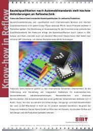
497,50<br />
<strong>Forced</strong> <strong>Convection</strong> <strong>Reflow</strong> <strong>Soldering</strong> <strong>System</strong><br />
<strong>SMT</strong> XXS (N 2)<br />
power supply<br />
2630<br />
pass through direction<br />
approx.<br />
100<br />
nitrogen supply<br />
Exhaust<br />
air<br />
153<br />
995<br />
830<br />
1521<br />
2232<br />
Subject to change withouth notice, 05/03/2012<br />
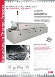
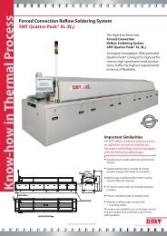
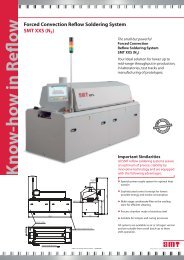
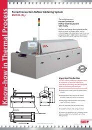
The small but powerful<br />
<strong>Forced</strong> <strong>Convection</strong><br />
<strong>Reflow</strong> <strong>Soldering</strong> <strong>System</strong><br />
<strong>SMT</strong> XXS (N 2 )<br />
Your ideal solution for lower up to<br />
mid-range throughput in production,<br />
in laboratories, test tracks and<br />
manufacturing of prototypes.<br />
Important Similarities<br />
All <strong>SMT</strong> reflow soldering systems assure<br />
an optimum of process stability by<br />
innovative technology and are equipped<br />
with the following advantages:<br />
Special power nozzle system for optimal heat<br />
transfer<br />
Sophisticated control concept for lowest<br />
possible energy and media consumption<br />
Multi-stage condensate filter at the cooling<br />
zone for efficient cleaning<br />
Process chamber made of stainless steel<br />
Suitable for temper and curing processes<br />
All systems are available as air or nitrogen version<br />
and are suitable from small batch up to three<br />
shift operation.
Technical Data <strong>SMT</strong> XXS (N 2)<br />
Overall dimensions<br />
Length:<br />
Width:<br />
Height (in delivery condition / incl. warning light): 2.)<br />
Inlet height, adjustable by customer: 2.)<br />
Weight<br />
Number / diameter foot:<br />
Max. floor loading:<br />
Process area<br />
Length:<br />
Pre-heating zones:<br />
Peak zone (top/bottom):<br />
Bottom heating modules pre-heating zones (option):<br />
Heated tunnel length, total:<br />
Active convection length:<br />
Length of cooling zone:<br />
Temperature measurement:<br />
Warm-up time:<br />
Heat transfer:<br />
Process temperature (pre-heating zone/peak zone):<br />
Transport chain conveyor<br />
Working width usable with PCB support:<br />
Pass through height (top/bottom):<br />
Max. loading:<br />
Transport mesh belt conveyor<br />
Usable working width:<br />
Pass through height (top):<br />
Max. loading:<br />
Conveyor speed<br />
Average conveyor speed<br />
Exhaustion 3.)<br />
Suction pipe:<br />
Required exhaust air at pipe (inlet):<br />
Temperature of exhaust air at the pipe:<br />
Internal exhaust air resistance of oven:<br />
Continuous sound pressure level<br />
Control Unit<br />
Nitrogen supply * 4.)<br />
Connecting armature (clamped joint for Cu-pipe):<br />
Working pressure (at connecting armature):<br />
N 2 -consumption, steady state condition and transport width 220 mm: 6.)<br />
N 2 -consumption, full load and transport width 220 mm: 7.)<br />
Readiness for the system (1000 ppm, N 2 < 5 ppm O 2 ):<br />
Power supply<br />
Connecting power supply:<br />
Max. current consumption per phase:<br />
Power consumption during heat-up:<br />
Power consumption steady state condition: 1.)<br />
1.) Machine with chain conveyor 220 mm transport width, fan regulation and no other options<br />
2.) Standard height 830 mm; corresponding to a changed inlet height the other heights of the reflow system are changing<br />
3.) Connection of a flexible, heat resisting (at least 100 °C) hose (available by <strong>SMT</strong>) or tube. The waste air exhausting unit width adjustable throttle valve<br />
mounted after the suction sleeves has to be installed by the user<br />
4.) Nitrogen supply with filters for solid and liquid parts has to be mounted by the user, recommended supply of nitrogen with oxygen content < 5 ppm<br />
6.) 1000 ppm with option „intelligent nitrogen control“ and „sleeping mode“; if 500 ppm then approx. 10 m³/h<br />
7.) With PCBs (220 x 220 mm), one PCB length distance, 1000 ppm; if 500 ppm then approx. 17 m³/h<br />
* with option nitrogen only<br />
Subject to change without notice 05/03/2012<br />
2630 mm<br />
995 mm<br />
1521 mm / 2232 mm<br />
830 ... 1030 ±20 mm<br />
approx. 1000 kg<br />
4 / 80 mm<br />
500 kg/m²<br />
2290 mm<br />
2<br />
1 peak zone with 2 heating modules (1 top/1 bottom)<br />
2<br />
1380 mm<br />
1085 mm<br />
910 mm<br />
NiCr-Ni sensors in the hot gas flow<br />
approx. 30 min.<br />
100% forced convection<br />
max. 300 °C (pre-heating zone) / 350 °C (Peak)<br />
60 ... 260 mm<br />
30/30 mm<br />
3 kg/m<br />
300 mm<br />
50 mm<br />
3 kg/m<br />
0.2 ... 3.0 m/min.<br />
0.2 ... 0.4 m/min.<br />
1 x Ø 153 mm<br />
approx. 300 … 400 m 3 /h<br />
< 50 °C<br />
3 - 8 mbar<br />
< 70 dB(A)<br />
CDIAS with RT 7<br />
R 3/8“ internal thread<br />
6 ... 8 bar<br />
approx. 9 m 3 /h<br />
approx. 15 m 3 /h<br />
approx. 15 min.<br />
3~N, PE 230 / 400 V, 50 Hz<br />
29 A<br />
19 kW<br />
approx. 5 kW h