Multiflex Wall Mount - Hycontrol
Multiflex Wall Mount - Hycontrol
Multiflex Wall Mount - Hycontrol

Create successful ePaper yourself
Turn your PDF publications into a flip-book with our unique Google optimized e-Paper software.
Elect. Iss. 01<br />
LIQUIFLEX<br />
MULTIFLEX<br />
PROGRAMMABLE LEVEL CONTROLLER<br />
PROGRAMMABLE LEVEL CONTROLLER<br />
INSTRUCTION MANUAL<br />
INSTRUCTION MANUAL<br />
HYCONTROL LIMITED<br />
Larchwood House, Orchard Street,<br />
Redditch, Worcestershire, B98 7DP.<br />
Tel: 01527 406800 Fax: 01527 406810<br />
Web: www.hycontrol.com<br />
Email: sales@hycontrol.comcom
MULTIFLEX MANUAL<br />
EDITION 2 : NOV 2000<br />
MULTIFLEX USER MANUAL - INDEX<br />
Introduction 1<br />
Page Drawings<br />
Section 1 Installation 2<br />
Transceiver <strong>Mount</strong>ing 2 Fig. 1<br />
Transceiver Wiring 3 Fig. 2<br />
Transducer <strong>Mount</strong>ing 4 Fig. 3<br />
Transducer Alternative <strong>Mount</strong>ing 5 Fig. 4<br />
Transducer <strong>Mount</strong>ing Faults 6 Fig. 5<br />
Transducer Stand Pipe 6<br />
Transducer Cable Extensions 7 Figs. 6 &<br />
7<br />
Temperature Sensor 8 Fig. 8<br />
Section 2 Easy Start for Liquiflex 9<br />
Quick Start Guide 9<br />
Principle of Programming 9<br />
Keypad Definitions 10<br />
To View Parameters 11<br />
Programming Example 12<br />
Programme Checking & Correction 13<br />
Section 3 Programming 14<br />
Principle of Programming 14<br />
Keypad Definitions 14<br />
Display Descriptions 14<br />
Security Code 15<br />
Application Programming 16<br />
Entering a New Programme 17<br />
Section 4 Parameter Index 18<br />
Parameter Definitions 19 to 34<br />
Section 5 Examples 35<br />
1. Level Measurement Mode 35<br />
2. Contents, Volume Conversion 36<br />
3. Pump Control 37<br />
4. Differential 38<br />
5. Open Channel Flow 39<br />
6. Open Channel Flow with Penstock 40<br />
Section 6 Commissioning Fault Finding 41<br />
APPENDIX 1 LINEARISATION OF SPECIAL 45<br />
VESSESLS OR FLUMES<br />
APPENDIX 2 SERIAL COMMUNICATIONS 49<br />
APPENDIX 3 SPECIFICATION 51<br />
APPENDIX 4 PARAMETER SETTINGS 52
INTRODUCTION<br />
<strong>Multiflex</strong><br />
ULTIFLEX PROGRAMMABLE LEVEL CONTROLLER<br />
USER MANUAL<br />
MULTIFLEX MANUAL 1<br />
EDITION 2 : NOV 2000<br />
SECTION 1<br />
<strong>Multiflex</strong> is a programmable multi-purpose level measurement instrument suitable for both solids<br />
and liquid applications. It consists of two elements, a wall mounted transceiver which has a display<br />
and an integral keypad for programming, and a transducer which must be mounted directly above the<br />
surface to be monitored .<br />
Ultrasonic pulses are transmitted by the transducer to the surface of the product to be monitored and<br />
are reflected back to the transducer. The time period between transmission and reception of the<br />
sound pulses is directly proportional to the distance between the transducer and the product.<br />
Since the speed of sound through air is affected by changes in temperature, a separate or integral (in<br />
the transducer) temperature sensor may be fitted to improve accuracy.<br />
<strong>Multiflex</strong> is capable of the following functions:-<br />
a) Level Measurement (height above datum)<br />
b) Distance Measurement (distance from datum)<br />
c) Volume Measurement<br />
d) Differential Level Measurement<br />
e) Open Channel Flow Measurement (O.C.M.)<br />
f) Pump Control<br />
WARNING<br />
DO NOT OPEN THE TRANSCEIVER DOOR WHEN THE<br />
POWER IS ON TO<br />
THE SUPPLY OR RELAY TERMINALS.
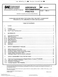
Transceiver<br />
<strong>Wall</strong> <strong>Mount</strong> - Figure 1<br />
INSTALLATION<br />
MULTIFLEX MANUAL 2<br />
EDITION 2 : NOV 2000<br />
SECTION 1<br />
Undo the 6 quarter turn screws on the front panel and open the hinged door to expose the mounting<br />
holes.<br />
<strong>Mount</strong> the unit on a flat surface and secure it via the 4 mounting holes moulded in the enclosure. DO<br />
NOT use excessive force when tightening the fixings and avoid any distortion of the enclosure.<br />
Ensure that the mounting surface is not subject to vibration and is not close to high voltage cables,<br />
contactors or drive controls. The unit should not be mounted in a confined space where temperatures<br />
may exceed the normal working temperature. If the unit is mounted outside it must be protected<br />
from direct sunlight and severe weather conditions.<br />
Remove the required number of hexagon blanking plugs from the bottom of the enclosure and<br />
replace them with appropriate conduit hubs or cable glands to maintain the I.P. rating.<br />
Figure 1:<br />
10 160<br />
RELAY 1<br />
RELAY 2<br />
3 HOLES<br />
20 DIA PLUGGED<br />
HI.TO<br />
1<br />
R1.HR<br />
5<br />
MULTIFLEX<br />
LO.TO HEAD FLOW<br />
2 3 4<br />
R2.HR R3.HR R4.HR<br />
6 7 8<br />
R1.ST R2.ST R3.ST R4.ST<br />
9<br />
0<br />
R5.HR GAIN<br />
CE<br />
#<br />
. -<br />
MODE TEST<br />
R5.ST TEMP DIST mA<br />
DSP<br />
ENT<br />
RELAY 3<br />
RELAY 4<br />
RELAY 5<br />
PROGRAMMABLE LEVEL CONTROLLER<br />
40<br />
130 CTRS<br />
HYCONTROL<br />
40<br />
228 CTRS<br />
240<br />
4 MOUNTING HOLES<br />
4.3 DIA (UNDER LID)<br />
90<br />
40
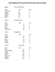
Electrical Connections - Figure 2<br />
MULTIFLEX MANUAL 3<br />
EDITION 2 : NOV 2000<br />
SECTION 1<br />
The instrument has two-part screw terminals. It can be powered from either an AC or DC supply.<br />
Figure 2:<br />
1 2 3<br />
E N L<br />
L2 L1<br />
AC POWER<br />
110/230 VAC<br />
+10%/-10%<br />
50/60 HZ 12VA<br />
19 20 21 22 23 24 25 26<br />
+ -<br />
4 5 6 7 8 9 10 11 12 13 14 15 16 17 18<br />
27 28<br />
+ -<br />
TRANS-<br />
TEMP<br />
DC POWER<br />
DUCER<br />
SENSOR<br />
21.6-30VDC<br />
9W<br />
RELAY 1 RELAY 2<br />
RELAY 3 RELAY 4 RELAY 5<br />
AC power supply connected:- Earth to terminal 1<br />
Neutral to terminal 2<br />
Live to terminal 3<br />
The instrument will automatically select either 110V or 230VAC ±10%, 50Hz or 60Hz, 12VA. A<br />
time lag fuse T160mA is fitted.<br />
DC power supply - connected :- Positive +ve to terminal 27<br />
Negative -ve to terminal 28<br />
The instrument will accept 24VDC + 25%, - 10%. 9W. A time lag fuse T315mA is fitted.<br />
5 SPDT Relays - rated at 8A/250VAC/30VDC resistive, with gold contacts for lower power<br />
switching, are connected at terminals 4 to 18, for activating external alarms, contactors, pumps etc..<br />
Transducer RXV15 - is connected:-Black to terminal 19<br />
Blue to terminal 20<br />
Screen to terminal 21<br />
Temperature compensated transducer RXT15 - is connected:-<br />
(Screen to terminal 19<br />
Must enable Pr.37 (Blue to terminal 20<br />
(Black to terminal 22<br />
Isolated Analogue - is connected :- Screen to terminal 24<br />
Positive +ve to terminal 25<br />
Negative -ve to terminal 26.<br />
Separate Temperature Compensation - when compensation is provided by a separate temperature<br />
sensor, the sensor should be connected with a shielded twisted pair and connected:-<br />
( Screen to terminal 21<br />
Must enable Pr.37 ( Core* to terminal 22<br />
( Core* to terminal 23<br />
* The polarity of the cores is unimportant, but it is important that the screen is<br />
connected only at the instrument end and not at the temperature sensor end.<br />
BLACK<br />
HOT.BLUE<br />
SHIELD<br />
SHIELD<br />
ISOLATED<br />
ANALOG<br />
OUTPUT
Transducer <strong>Mount</strong>ing<br />
The transducers can be supplied separately or mounted in a Teflon faced flange for applications<br />
requiring chemical compatibility. Figures 3 and 3a show the dimensions:<br />
Figures 3 and 3a:<br />
21<br />
100<br />
10m cable<br />
6.9 dia<br />
95<br />
72<br />
M20 x 1.5<br />
MULTIFLEX MANUAL 4<br />
EDITION 2 : NOV 2000<br />
50<br />
Isolation Kit<br />
Fit as shown<br />
Bolt hole PCD to suit<br />
flange selected<br />
Dia to suit flange selected<br />
SECTION 1<br />
An isolation kit is provided with each transducer to minimise any ringing transmitted through the<br />
mounting structure. Its use is optional on flanged transducers (for terminating conduit).<br />
The transducer must be mounted perpendicular to the monitored surface and, ideally, at least 0.5<br />
metres above its maximum level.<br />
The transducer has a 10° inclusive conical beam angle at 3dB and must be mounted with a clear<br />
unobstructed sight of the product to be measured, over the complete measurement range.<br />
The beam "footprint" = approx. 20% of the distance to the product.<br />
The transducer is provided with integral cable which can be extended up to 300 metres using a<br />
suitable junction box and RG62AU cable for the standard transducer. The temperature compensated<br />
transducer requires an additional single core screen extension. Alternatively you can use screened<br />
twin-axial Beldon 9207 or equal for either type of transducer; refer to Fig.6.<br />
Transducer cables and temperature compensation cables can be run together but should be separated<br />
from power cables by at least 150mm and preferably installed in their own earthed steel conduit.<br />
20<br />
No. & size of bolts<br />
to suit flange selected<br />
20<br />
170
Figure 4: Alternative mounting arrangements for transducers<br />
FLEXIBLE OR RIGID<br />
CONDUIT.<br />
ISOLATION KIT.<br />
BRACKET.<br />
INTEGRAL FLANGE WITH PTFE FACE.<br />
OPTIONAL<br />
ISOLATION KIT<br />
Do not mount transducers incorporating temperature compensation in direct sunlight.<br />
Do not over-tighten the bolts on flange construction transducers.<br />
Flange transducers are not pressure rated and are suitable only for atmospheric pressure.<br />
MULTIFLEX MANUAL 5<br />
EDITION 2 : NOV 2000<br />
ISOLATION KIT.<br />
UNDER FLANGE.<br />
SLIP-ON FLANGE.<br />
SECTION 1<br />
CENELEC approved transducers must be mounted and wired in accordance with the appropriate<br />
National Standards concerning installation in hazardous environments.<br />
For differential applications mount both transducers at the same height above the zero datum point.<br />
For open channel flow applications the transducer must be mounted upstream of the flume or weir<br />
as detailed in BS3680 (usually 3 or 4 times maximum head).
Figure 5:<br />
Standpipe Installations<br />
CAUTION: AVOID THE FOLLOWING TRANSDUCER INSTALLATION FAULTS<br />
DO NOT AIM THROUGH<br />
HOLES IN THE TANK.<br />
KEEP TRANSDUCER<br />
PERPENDICULAR<br />
TO LIQUID.<br />
AVOID ROUGH<br />
EDGES<br />
IN STANDPIPES.<br />
AVOID INFLOWS OR<br />
OTHER OBSTRUCTIONS.<br />
MULTIFLEX MANUAL 6<br />
EDITION 2 : NOV 2000<br />
KEEP TRANSDUCERS AND<br />
TEMPERATURE COMPENSATION<br />
PROBES OUT OF DIRECT<br />
SUNLIGHT<br />
SECTION 1<br />
In many applications access to a vessel must be made via a standpipe. It is necessary to observe some<br />
basic rules when fitting transducers into standpipes.<br />
BLANKING: Parameter 5 should always be set at least 150mm longer<br />
than the length of the standpipe.<br />
STANDPIPE should be in accordance with the following table<br />
DIMENSIONS:<br />
Bore of Standpipe Maximum length<br />
of Standpipe<br />
3" ( 75mm) 300mm<br />
4" (100mm) 300mm<br />
6" (150mm) 400mm<br />
8" (200mm) 600mm<br />
12" (300mm) 600mm<br />
e.g. Using a 4" flanged transducer would require the standpipe length to be no more than<br />
300mm and Pr.5 set at 450mm minimum.<br />
Note that 4" / 100mm is the maximum integral transducer flange size.<br />
The inside of the pipe and joint with vessel top must be clean and free of any<br />
obstructions, seams or welds.
Transducer Cable Extensions<br />
Transducer cables may be extended using a junction box as shown in Figure 6:<br />
Figure 6:<br />
Transducer<br />
Black<br />
Screen<br />
Blue<br />
Blue<br />
Standard Transducer<br />
Transceiver<br />
Junction<br />
Screen - Term 19<br />
RG62AU<br />
Core - Term 20<br />
Standard Transducer- alternative<br />
Transducer<br />
Transceiver<br />
Junction<br />
Black<br />
Screen<br />
Figure 7: Transducer Wiring for Differential Mode<br />
Upstream Transducer<br />
Junction<br />
Black<br />
Screen<br />
Blue<br />
Downstream Transducer<br />
Junction<br />
Black<br />
Screen<br />
Blue<br />
1 2 3<br />
E N L<br />
L2 L1<br />
AC POWER<br />
110/230 VAC<br />
+10%/-10%<br />
50/60 HZ 12VA<br />
MULTIFLEX MANUAL 7<br />
EDITION 2 : NOV 2000<br />
Blue<br />
Temperature Compensation Transducer<br />
Transducer<br />
Black<br />
Screen<br />
Copper core T19<br />
Beldon 9207<br />
Screen T21<br />
or equal<br />
Silver core T20<br />
Transceiver<br />
Screen - Term 19<br />
RG62AU<br />
Core - Term 18<br />
Transceiver<br />
Screen - Term 21<br />
RG62AU<br />
Core - Term 16<br />
RELAY 1 RELAY 2 RELAY 3<br />
NOTE LINK<br />
Junction<br />
Transceiver<br />
Extend transducer cable if necessary<br />
with RG62AU as shown.<br />
SECTION 1<br />
Copper core T22<br />
Beldon 9207<br />
Screen T19<br />
or equal<br />
Silver core T20<br />
UP & DOWNSTREAM SHIELDS<br />
19 20 21 22 23 24 25 26<br />
4 5 6 7 8 9 10 11 12 13 14 15 16 17 18<br />
+ -<br />
RELAY 4 RELAY 5<br />
Wire unextended transducers as below<br />
DOWNSTREAM - BLUE<br />
UPSTREAM - BLUE<br />
UP & DOWNSTREAM BLACKS<br />
BLACK<br />
TRANS-<br />
DUCER<br />
HOT.BLUE<br />
SHIELD<br />
TEMP<br />
SENSOR<br />
SHIELD<br />
ISOLATED<br />
ANALOG<br />
OUTPUT<br />
27 28<br />
+ -<br />
DC POWER<br />
21.6-30VDC<br />
9W
Temperature Sensor<br />
MULTIFLEX MANUAL 8<br />
EDITION 2 : NOV 2000<br />
SECTION 1<br />
If a separate temperature sensor is used it must be mounted where it will monitor temperature<br />
changes of the air between the transducer and the product. This is usually adjacent to the transducer,<br />
but should not be in direct sunlight and should be protected from wind chill.<br />
Figure 8:<br />
85 dia<br />
85 DIA<br />
LOCK<br />
SCREW<br />
52<br />
72 DIA<br />
53<br />
5 REF<br />
30 dia<br />
34 ref<br />
35<br />
175<br />
HOUSING: CAST IRON BLACK EPOXY PAINT<br />
CLASSIFICATION EEx e II T6/IP 65<br />
PROBE: 316ST. STEEL<br />
M20 x 1.5<br />
EXTERNAL<br />
EARTH<br />
15<br />
28 DIA<br />
12<br />
M20 x 1.5<br />
20 25 50<br />
150<br />
25<br />
33 HEX<br />
3/4" BSPP<br />
50<br />
9 dia<br />
+ POLARITY<br />
- UNIMPORTANT<br />
TEMPERATURE SENSOR RTS 2B<br />
10 DIA<br />
BLUE<br />
RED<br />
TERMINALS<br />
(VIEWED ON TOP)<br />
HOUSING: POLYCARBONATE<br />
PROBE:316 SS<br />
TEMPERATURE SENSOR RTS 2<br />
TERMINALS ARE NOT POLARISED<br />
INTERNAL<br />
EARTH
EASY START FOR MULTIFLEX<br />
MULTIFLEX MANUAL 9<br />
EDITION 2 : NOV 2000<br />
SECTION 2<br />
The <strong>Multiflex</strong> system requires programming by the operator to obtain the required measurements and<br />
control. To create a basic working system, only parameters 1 to 6 need be programmed. To become<br />
familiar with the use of the system, the following QUICK START guide can be used before the<br />
instrument is fully programmed.<br />
Quick Start Guide<br />
1. Connect power and transducer cables as previously described.<br />
2. Close the front cover before switching on the power.<br />
The instrument is factory set for distance measurement up to 15m range.<br />
3. Hold the transducer approximately 1.5 metres from a flat surface and switch on.<br />
After a short period, the display will show the distance (e.g. 1.50) between the transducer and<br />
the surface.<br />
If the transducer is now moved slowly towards the surface, the reading should decrease. This shows<br />
that the unit is correctly wired and is operating as expected in response to the reduction in distance.<br />
If the reading increases as the transducer is moved towards the surface, it indicates that the unit has<br />
been previously programmed to read level not distance.<br />
Principle of Programming<br />
The <strong>Multiflex</strong> has two modes:-<br />
a) RUN (Normal operating)<br />
b) PROG (Programming)<br />
In the 'RUN' mode, the instrument monitors the target, displaying values and setting outputs<br />
as programmed by the operator.<br />
In the 'PROG' mode the operator uses the keypad in conjunction with the display to adjust the<br />
settings and to test that the unit is programmed correctly.
Keypad Definitions<br />
MULTIFLEX MANUAL 10<br />
EDITION 2 : NOV 2000<br />
SECTION 2<br />
The keypad has 20 keys which are used to programme the operation of the instrument. These keys<br />
also have secondary functions indicated above them (See Figure 1) enabling the operator to view the<br />
results being obtained by the instrument during its normal 'RUN' cycle.<br />
Primary Key Functions<br />
0 - 9 Numerical Values<br />
Decimal Point<br />
— Negative value (also used to slow down simulation)<br />
CE Clear Entry (also used to leave test functions Pr.75 to Pr.78.)<br />
# Returns display to normal 'RUN' mode after viewing secondary<br />
functions (also speeds up simulation Pr.78)<br />
MODE Alternates between 'RUN' and 'PROG' mode.<br />
TEST Displays gain or confidence in 'RUN' mode and allows<br />
parameter interrogation and simulation hold in 'PROG' mode.<br />
'▲' Increase parameter number (also control of simulation<br />
direction).<br />
'▼' Decrease parameter number (also control of simulation<br />
direction)<br />
DSP Display parameter number/value alternately.<br />
ENT Enter a new value or initiate a system test under Pr.75 to Pr.78<br />
Active Secondary Key Functions<br />
During normal 'RUN' mode the operator can obtain the data defined as secondary function<br />
without interrupting normal operation, by pressing the appropriate key, i.e.<br />
Keys 1 - 4 Show high totaliser, low totaliser, head and flow<br />
when in the OCM mode; head is water level.<br />
Key 5 Relay 1. Hours energised.<br />
Key 6 Relay 2. Hours energised.<br />
Key 7 Relay 3. Hours energised.<br />
Key 8 Relay 4. Hours energised.<br />
CE Relay 5. Hours energised.<br />
Key 9 Relay 1. Number of times energised.<br />
Key 0 Relay 2. Number of times energised.<br />
Relay 3. Number of times energised.<br />
— Relay 4. Number of times energised.<br />
'▲' Relay 5. Number of times energised.<br />
Test Displays gain or confidence.<br />
ENT Displays mA output.<br />
DSP Displays distance from the transducer face.<br />
'▼' Displays temperature.
To View Parameters<br />
MULTIFLEX MANUAL 11<br />
EDITION 2 : NOV 2000<br />
SECTION 2<br />
The operational programme is contained within the parameters listed on Page 18. Each parameter<br />
instructs the unit to carry out a specific function. To look at the complete list of parameters and the<br />
options available see Section 4 but as an initial guide proceed as follows:-<br />
Press 'MODE', the display will show 'PROG'. (there may be a delay of up to 6 seconds if the<br />
instrument is busy). Press '1' to obtain a display of Pr.01 or the previous parameter number used.<br />
It is now possible to key in any parameter number, via the keypad. To display its value press 'DSP'.<br />
To return to the parameter number press 'DSP' again.<br />
To view a sequence of parameter numbers, enter the first one that is of interest and then press<br />
'▲' to increase the parameter number or '▼' to decrease the parameter number.<br />
Similarly, if a parameter value is displayed then pressing '▲' or '▼' key will momentarily flash the<br />
next parameter number and then display that parameter value.<br />
Press 'MODE' to return to the 'RUN' mode<br />
If a key is not pressed for a period of 30 seconds the unit will automatically return to the run<br />
mode.<br />
To change a Parameter - Programming<br />
Press 'MODE' to display 'PROG'<br />
Whilst 'PROG' is displayed press '1' and the display will<br />
show either Pr.01 or previous Pr. number.<br />
If not Pr.01 then press '1' to obtain display of Pr.01.<br />
Press 'DSP' to display the value of Pr.01<br />
Press 'ENT' and the display will show 'COdE' requesting that a<br />
security code is entered.<br />
Press '9753' to enter the factory set security code. (See Page 15 to change code).<br />
Press 'ENT' and the display will blink and show either the default value of Pr.01<br />
which is 2, or any other value previously programmed into it.<br />
The unit is now ready to be programmed.<br />
NOTE:- Whenever 'COdE' is displayed, re-enter the security code.<br />
In the previous programme, the display is now showing the value entered in 'Pr.01'.<br />
To change the value of this entry press the new value required and press 'ENT'. For our example<br />
press 1 and 'ENT' and the value of Pr.01 will change to 1 which means it is in level mode, i.e.<br />
measuring product height above datum.<br />
Then using the '▲' key move to the other parameters that require changing.<br />
To change the value of any other parameter either use the '▲' key to move to higher Pr numbers, or<br />
press 'DSP' and then enter the Pr number required and press 'DSP' again to display its value.
Programming Example<br />
MULTIFLEX MANUAL 12<br />
EDITION 2 : NOV 2000<br />
SECTION 2<br />
The following example shows how to continue programming from the previous stage to achieve a<br />
simple level application including setting a high alarm.<br />
1.5<br />
(Pr.3)<br />
0.5 (Pr.5)<br />
1.0 (Pr.4)<br />
Having changed the value in Pr.1 to 1 (level)<br />
Press ▲ Display Pr.02 = 2 (units in metres)<br />
▲ Change Pr.03 = 1.5 (empty distance)<br />
▲ Change Pr.04 = 1.0 (operational span)<br />
▲ Display Pr.05 = 0.5 (blanking distance)<br />
▲ Display Pr.06 = 1.0 (rate of change of level in metres)<br />
Press Pr.08 Change Pr.08 = 1 (relay 1 designated normally energised)<br />
▲ Change Pr.09 = 0.7 (relay 1 set)<br />
▲ Change Pr.10 = 0.5 (relay 1 re-set)<br />
MODE to return to normal running.<br />
For a full description of parameter options refer to Section 4.<br />
Relay 1 Reset<br />
0.5 (Pr.10)<br />
Relay 1 Set<br />
0.7 (Pr.9)<br />
Note: The display does not show the decimal point until the first decimal figure is keyed in.
Programme Checking.<br />
MULTIFLEX MANUAL 13<br />
EDITION 2 : NOV 2000<br />
SECTION 2<br />
To check that the previous programme functions properly, hold the transducer approximately 1.5m<br />
above a surface; the display will read approximately zero.<br />
If it displays LOST it is because the transducer is more than the 1.5 metre (distance to furthest point)<br />
from your target. Go closer and wait for LOST to change to 0.00 and then to a level display.<br />
By slowly moving the transducer towards the surface the display will increase, simulating a rising<br />
level. When the display exceeds 0.7 the relay will switch, indicated by the LED "RELAY 1" and, if<br />
the transducer is then raised, the display will decrease and the relay will reset below 0.5.<br />
Programme Correction or Resetting to Factory Defaults.<br />
If at any time you feel that a mistake has been made, the following routine clears the programme<br />
back to the known starting position of the factory set values shown on page 52.<br />
It is also advisable to return to the factory default values before building a programme for a new<br />
application. This is achieved as follows:-<br />
Press 'MODE' to display 'PROG'<br />
" '1' immediately to display a Pr number.<br />
" '99' to display Pr.99<br />
" 'DSP' to show '===='<br />
" 'CE' to clear the display<br />
" 'ENT' to display COdE, requesting the security code.<br />
" '9753'<br />
" 'ENT' the display will now show 'P.rES' followed by 't.rES' and finally '===='<br />
" 'DSP' to display 'Pr.99'<br />
" '1' to display 'Pr.01'. The new programme can now be entered.<br />
The above is a brief introduction.<br />
To understand programming completely it is necessary to read the detailed section describing<br />
Programming, Section 3, along with the parameter descriptions, Section 4, and the examples, Section<br />
5, before continuing.
Principle<br />
PROGRAMMING<br />
MULTIFLEX MANUAL 14<br />
EDITION 2 : NOV 2000<br />
SECTION 3<br />
The principle of programming and the two modes 'run' and 'PROG' have already been described on<br />
page 9.<br />
Keypad Definitions<br />
Are fully described on page 10.<br />
Display Descriptions<br />
The following display codes are used:-<br />
PROG Precedes programme mode<br />
run Precedes run mode<br />
Pr.XX Parameter number<br />
COdE Security code request<br />
'====' No value<br />
FULL Numerical overflow of display ) i.e. value too large to display.<br />
-FUL Negative numerical overflow ) Check that Pr.43 is correct.<br />
P.rES Resetting to factory parameters<br />
t.rES Resetting totalisers<br />
LOSt Loss of echo<br />
tESt System performing a requested test<br />
gAIN Gain value being displayed<br />
HEAd Head<br />
FLO Flow<br />
HI.tO Totaliser high 4 digits 9999 (----) max. reading<br />
LO.tO Totaliser low 4 digits (----) 9999 max. reading<br />
deG.C Temperature °C<br />
dISt Distance<br />
An.OP Analogue output
Security Code<br />
MULTIFLEX MANUAL 15<br />
EDITION 2 : NOV 2000<br />
SECTION 3<br />
The programme includes security code protection. Any operator can display the value of a parameter,<br />
but any attempt to enter a new value or perform a test will result in the security code being requested.<br />
The security code is requested by the prompt of 'COdE', if the code is not entered correctly this<br />
prompt is re-displayed.<br />
Once the code has been input correctly, it will not be required again whilst the system remains in the<br />
'PROG' mode. The factory set value is 9753.<br />
A new "customer's" security code, comprising 4 numerical digits, can be entered via Pr.96, providing<br />
the unit is in programme mode. The range of acceptable values is 1000 to 9999. If an invalid code is<br />
entered, the instrument will default to a code number 9753.<br />
The code number is scrambled immediately on entry.<br />
If you forget your security code ring your supplier for advice quoting the number stored in Pr.96.
Application Programming<br />
MULTIFLEX MANUAL 16<br />
EDITION 2 : NOV 2000<br />
SECTION 3<br />
The programming is controlled by the parameters detailed later in this section. Programming is easy<br />
to follow because the parameters available to the programmer fall into distinct groups:-<br />
Pr.1 - Pr.7 Basic set up<br />
Pr.8 - Pr.22 Relays 1 to 5 designation and settings<br />
Pr.23 - Pr.29 Failsafe operation<br />
Pr.30 - Pr.34 Set the analogue output<br />
Pr.37 - Pr.39 Temperature compensation<br />
Pr.40 - Pr.44 Volume conversion<br />
Pr.45 - Pr.50 Open Channel Flow Metering<br />
Pr.51 - Pr.57 Specialised Pump Control<br />
Pr.62 - Pr.63 Serial Communications<br />
Pr.68 - Pr.70 Select echo detection and processing<br />
Pr.71 - Pr.74 Miscellaneous<br />
Pr.75 - Pr.78 Test Parameters<br />
Pr.95 - Pr.96 Number Stores<br />
Pr.97 - Pr.99 Resets<br />
It can be seen from the above which distinct groups of parameters need to be considered for a<br />
particular application. For instance, in an application to measure level, it may be necessary to<br />
consider only Pr.1 to Pr.29 which are relative to basic set-up, relays and failsafe.<br />
It is good practice to carry out a programme reset on a new application before starting programming<br />
as this will return all parameters to factory defaults and any parameters which are not required for the<br />
new application will remain at default, ensuring that the programme runs correctly.<br />
Default values for each parameter are shown in the parameter definition , Section 4, and in the<br />
Parameter Setting table, Page 52.<br />
Programming<br />
The following is the programming sequence to set up a unit for operation. If you have not done this<br />
before, refer back to Section 2, Easy Start.<br />
1. Designing a Programme<br />
From the information contained within this manual and the knowledge of the application, produce on<br />
paper the correct values for the parameters required (use page 52 for the parameter entries).<br />
To help you with this see the examples in Section 5 on pages 35 to 40.<br />
Details of all the parameter options are listed on pages 19 to 34.
2. Entering a new Programme<br />
Sequence to enter a new programme or to modify the existing one.<br />
MULTIFLEX MANUAL 17<br />
EDITION 2 : NOV 2000<br />
SECTION 3<br />
a. Press 'MODE'. When display shows "PROG" press '1' and then press 'DSP' followed<br />
by 'ENT'.<br />
b. Display will show COdE and the security code must be entered (factory default is<br />
9753. For a new code see page 15).<br />
c. Display will now show the value of Pr.01 or the last Pr. number used, indicating that<br />
the correct security code has been entered.<br />
If the unit is being programmed for a new application it is recommended that all parameters are reset<br />
to the factory programmed values as follows:-<br />
d. 1. Display Pr.99<br />
2. Press 'DSP' to show '===='<br />
3. Press 'CE' to obtain a clear display<br />
4. Press 'ENT' and the display will show 'P.rES' then 't.rES' and then '===='<br />
5. Press 'DSP' and enter Pr.01<br />
6. Press 'DSP' to display the value of Pr.01<br />
If a modification is being made to an existing programme then the sequence re-commences here.<br />
e. The new values for any parameter should be input, checking that the value is stored<br />
correctly. The parameters can be accessed sequentially using '▲' and '▼' keys or<br />
individually by entering the required parameter number.<br />
f. Before entering the 'RUN' mode, the programme can be checked by pressing Pr.78<br />
then 'DSP' then 'ENT'. <strong>Multiflex</strong> will now simulate the operating programme (except<br />
in differential mode) providing display, analogue output and relay functions.<br />
CAUTION: All outputs will work under simulation, so ensure that external<br />
connections will not cause damage.<br />
g. Press 'CE' to leave simulation.<br />
h. Press 'TEST' to freeze and unfreeze simulation.<br />
i. When the programme is complete and does not require further modification press<br />
'MODE' to return to the 'RUN' condition.
Basic Set-up<br />
Pr.1<br />
Pr.2<br />
Pr.3<br />
Pr.4<br />
Pr.5<br />
Pr.6<br />
Pr.7<br />
Relays<br />
Pr.8<br />
Pr.9<br />
Pr.10<br />
Pr.11<br />
Pr.12<br />
Pr.13<br />
Pr.14<br />
Pr.15<br />
Pr.16<br />
Pr.17<br />
Pr.18<br />
Pr.19<br />
Pr.20<br />
Pr.21<br />
Pr.22<br />
Failsafe<br />
Pr.23<br />
Pr.24<br />
Pr.25<br />
Pr.26<br />
Pr.27<br />
Pr.28<br />
Pr.29<br />
Analogue<br />
Pr.30<br />
Pr.31<br />
Pr.32<br />
Pr.33<br />
Pr.34<br />
Temperature<br />
Pr.37<br />
Pr.38<br />
Pr.39<br />
Volume<br />
Conversion<br />
Pr.40<br />
Pr.41<br />
Pr.42<br />
Pr.43<br />
Pr.44<br />
Application<br />
Units<br />
Empty Distance<br />
Operational Span<br />
Blanking Distance<br />
Rate of change<br />
Decimal Display<br />
Relay 1<br />
Relay 1 Set<br />
Relay 1 Reset<br />
Relay 2<br />
Relay 2 Set<br />
Relay 2 Reset<br />
Relay 3<br />
Relay 3 Set<br />
Relay 3 Reset<br />
Relay 4<br />
Relay 4 Set<br />
Relay 4 Reset<br />
Relay 5<br />
Relay 5 Set<br />
Relay 5 Reset<br />
Failsafe R1<br />
Failsafe R2<br />
Failsafe R3<br />
Failsafe R4<br />
Failsafe R5<br />
Failsafe Analogue<br />
Failsafe Time Delay<br />
Analogue Output<br />
Analogue Options<br />
Analogue Datum<br />
Analogue Span<br />
Analogue Test<br />
Probe enable<br />
Temp. Compensation<br />
Probe test<br />
Vessel shape<br />
Dimension 'H'<br />
Dimension 'L'<br />
Display Conversion<br />
Volume Linearisation<br />
PARAMETER INDEX<br />
Open Channel Flow<br />
Pr.45<br />
Pr.46<br />
Pr.47<br />
Pr.48<br />
Pr.49<br />
Pr.50<br />
Pump Controls<br />
Pr.51<br />
Pr.52<br />
Pr.53<br />
Pr.54<br />
Pr.55<br />
Pr.56<br />
Pr.57<br />
Serial<br />
Communications<br />
Pr.62<br />
Pr.63<br />
Echo Detection<br />
Pr.68<br />
Pr.69<br />
Pr.70<br />
Miscellaneous<br />
Pr.71<br />
Pr.72<br />
Pr.73<br />
Pr.74<br />
Test Parameters<br />
Pr.75<br />
Pr.76<br />
Pr.77<br />
Pr.78<br />
Number Store<br />
Pr.95<br />
Pr.96<br />
Reset<br />
Pr.97<br />
Pr.98<br />
Pr.99<br />
MULTIFLEX MANUAL 18<br />
EDITION 2 : NOV 2000<br />
Flow exponent<br />
Max. Flow Rate<br />
Time Base for Flow Rate<br />
Totalise Display Conversion<br />
Control of Ext. Counter<br />
Penstock Control<br />
Pump Sequence<br />
Duty Standby<br />
Pump Exerciser<br />
Pump Tolerance<br />
Pump Maintenance<br />
Run-on-Interval<br />
Run-on-Time<br />
Serial Comms enable<br />
Station No.<br />
Echo Selection Algorithm<br />
Check Search<br />
Echo Velocity<br />
Correction Value<br />
Parameter Display<br />
Software Revision Number<br />
Reset Counter<br />
Digital Output Set<br />
HardwareTest<br />
Transmitter Test<br />
Simulation<br />
Serial Number Store<br />
Security Code Store<br />
Relay Hours/Starts Totaliser<br />
Reset<br />
OCM Totaliser Reset<br />
Full System Reset<br />
NOTE: All other parameters are unused and should not be changed.<br />
SECTION 4
PARAMETER DEFINITIONS<br />
MULTIFLEX MANUAL 19<br />
EDITION 2 : NOV 2000<br />
SECTION 4<br />
The parameters define all the options that are available to the operator of the instrument. It may be<br />
easier to read these in conjunction with the application examples on pages 35 to 40.<br />
NOTE:- (D=) factory default entry for that parameter.<br />
Basic Set-up<br />
Pr.1 Basic Application (D=2)<br />
Enter 1 - Level Measurement<br />
2 - Distance Measurement<br />
3 - Differential Level Measurement (DLD)<br />
4 - Open Channel Flow Metering (OCM)<br />
Pr.2 Calibration/Display Units (D=2)<br />
Enter 1 - Feet<br />
2 - Metres To display in percent of span,<br />
3 - Inches set Pr.40 to 1.<br />
4 - Centimetres<br />
The system will be set to work in the specified units but the display can be made to display a<br />
percentage, a converted value or a volume (Pr.40).<br />
NOTE: Any subsequent change of units in Pr.2 (i.e. Pr.2 = 1-4) will reset parameters<br />
Pr.3 to Pr.6 to new units and all other parameters will default to factory resets.<br />
Pr.3 Empty Distance (D=15.00)<br />
The distance from the face of transducer to the furthest point away, usually the bottom of the<br />
container or channel. Enter the distance in the units selected in Pr.2.<br />
Resolution is a function of this parameter.<br />
Pr.4 Operational Span (D=15.00)<br />
The distance between the furthest and nearest points over which measurement is required.<br />
Enter the distance in the units selected in Pr.2<br />
For differential applications, the value required is the maximum difference in the levels to be<br />
measured.
Pr.5 Blocking or Blanking Zone (D=0.50)<br />
MULTIFLEX MANUAL 20<br />
EDITION 2 : NOV 2000<br />
SECTION 4<br />
The distance in front of the transducer, within which the product should not enter, and within<br />
which no return echoes will be processed. It is important to ensure that the product being<br />
monitored does not enter this zone.<br />
Enter in the units selected in Pr.2<br />
DO NOT REDUCE THE FACTORY SET VALUE WITHOUT REFERENCE TO HYCONTROL.<br />
Pr.6 Rate of Change (D=1.00)<br />
This value should be as small as possible but greater than the maximum rate of change of<br />
level. Do not change this value unless you know that the rate of change is greater than<br />
1.0m/min or that the system continually 'tracks' a level lower than the actual level.<br />
If it is necessary to change the value, enter the new value in units per minute selected in Pr.2.<br />
The suggested range of values is 0.1 to 10 metres/min or the equivalent.<br />
Pr.7 Decimal Display (D=2)<br />
0 = No decimal places allowed.<br />
1 = Up to 1 decimal place allowed.<br />
2 = Up to 2 decimal places allowed<br />
3 = Up to 3 decimal places allowed<br />
Relays<br />
The 5 relays can be assigned to various functions depending on the application, as shown<br />
below:<br />
Hysteresis is fully adjustable, so for most functions it is necessary to enter both "set" and<br />
"reset" values.<br />
The relay state under normal operating conditions is defined as:-<br />
(e) = normally energised. De-energise when "set" value is reached.<br />
(d) = normally de-energised. Energise when "set" value is reached.<br />
"Failsafe" functions are detailed in Pr.23 - 27.<br />
The relays can be programmed to give both high and low alarm or to control levels.<br />
e.g. High alarm Set: 2.0m Low Alarm Reset: 0.5m<br />
Reset 1.8m Set 0.2m<br />
The system will automatically configure itself as high or low alarm depending on which of<br />
the set and reset entries has the higher value.<br />
Note that on distance measurement only (Pr.1 = 2), the higher value is furthest from the<br />
transducer.<br />
Defaults are 0 for relay designations 8, 11, 14, 17 and 20.<br />
Defaults are 0.00 for relay settings 9 & 10, 12 & 13, 15 & 16, 18 & 19, and 21 & 22.
The relays are controlled from parameters 8-22 as follows:-<br />
Relay 1 Relay 2 Relay 3 Relay 4 Relay 5<br />
Designation Pr. 8 Pr.11 Pr.14 Pr.17 Pr.20<br />
Set (l.e.d. on) Pr. 9 Pr.12 Pr.15 Pr.18 Pr.21<br />
Reset (l.e.d. off) Pr.10 Pr.13 Pr.16 Pr.19 Pr.22<br />
The application/relay function options are shown on the following tables:-<br />
MULTIFLEX MANUAL 21<br />
EDITION 2 : NOV 2000<br />
SECTION 4<br />
Pr.8 BASIC APPLICATION - RELAY FUNCTION<br />
Relay 1<br />
Pr.1=1/Pr.1=2<br />
Pr.1=3<br />
Pr.1=4<br />
Designation<br />
Level/Distance<br />
Differential<br />
Open Channel Flow<br />
ENTER: 0 Off Off Off<br />
1.00 Level Alarm (e) Level Alarm on (e)<br />
Either Transducer<br />
Level Alarm (e)<br />
2.00 Level Control (d) Differential Alarm (e) Level Control (d)<br />
3.00 Off Differential Control (d) Flow alarm (e)<br />
4.00 Off Downstream Level Alarm (e) Off<br />
5.00 Off Upstream Level Alarm (e) Off<br />
6.00 Temperature Alarm (e) Temperature Alarm (e) Temperature Alarm (e)<br />
7.00 Loss of Echo (e) Loss of Echo (e) Loss of Echo (e)<br />
8.00 Run Programme (e) Run Programme (e) Run Programme (e)<br />
Pr.9<br />
(e) = Normally energised (d) = Normally de-energised<br />
De-energise to alarm Energise to start (motor)<br />
For Level/Differential: ENTER values in display unit as selected at Pr.2<br />
Relay 1<br />
For Flow ENTER values in unit selected at Pr.46<br />
Set<br />
Pr.10<br />
Relay 1<br />
Reset<br />
For Temperature: ENTER values in deg C. (valid only if probe or RXT fitted)<br />
For Totaliser: Refer to Pr.49<br />
For Loss of Echo or Run/Prog. No set/reset entries are required.<br />
Pr.11<br />
Relay 2 Designation<br />
Identical to Pr.8<br />
Pr.12 Relay 2 Set Identical to Pr.9<br />
Pr.13<br />
Relay 2 Reset<br />
Identical to Pr.10<br />
Pr. 14<br />
Relay 3 Designation<br />
Identical to Pr.8<br />
Pr. 15 Relay 3 Set Identical to Pr.9<br />
Pr. 16<br />
Relay 3 Reset<br />
Identical to Pr.10<br />
Pr.17<br />
Relay 4 Designation<br />
Identical to Pr.8<br />
Pr.18 Relay 4 Set Identical to Pr.9<br />
Pr.19<br />
Relay 4 Reset<br />
Identical to Pr.10
BASIC APPLICATION - RELAY FUNCTION<br />
Pr.20<br />
Relay 5<br />
Pr.1=1/Pr.1=2<br />
Pr.1=3<br />
Pr.1=4<br />
Designation<br />
Level/Distance<br />
Differential<br />
Open Channel Flow<br />
ENTER: 0 Off N/A Off<br />
1.00 Level Alarm (e) N/A Level Alarm (e)<br />
2.00 Level Control (d) N/A Level Control (d)<br />
3.00 Off N/A Flow alarm (e)<br />
4.00 Off N/A Off<br />
5.00 Off N/A Totaliser Drive (d)<br />
6.00 Temperature Alarm (e) N/A Temperature Alarm (e)<br />
7.00 Loss of Echo (e) N/A Loss of Echo (e)<br />
8.00 Run Programme (e) N/A Run Programme (e)<br />
Pr.21<br />
(e) = Normally energised (d) = Normally de-energised<br />
De-energise to alarm Energise to start (motor)<br />
For Level/Differential: ENTER values in display unit as selected at Pr.2<br />
Relay 5<br />
For Flow ENTER values in unit selected at Pr.46<br />
Set<br />
Pr.22<br />
Relay 5<br />
Reset<br />
For Temperature: ENTER values in deg C. (valid only if probe or RXT fitted)<br />
For Totaliser: Refer to Pr.49<br />
For Loss of Echo or Run/Prog. No set/reset entries are required.<br />
Failsafe (D = 3 for all)<br />
MULTIFLEX MANUAL 22<br />
EDITION 2 : NOV 2000<br />
SECTION 4<br />
On loss of power all relays will de-energise.<br />
For other fault conditions e.g. damaged transducer, the failsafe relay state (after time delay selected at<br />
Pr.29), is selectable:-<br />
Pr.23 Relay 1 - Failsafe)<br />
Pr.24 Relay 2 - Failsafe) > Enter 1 - Energise ) One option for<br />
Pr.25 Relay 3 - Failsafe) 2 - De-energise ) each relay<br />
Pr.26 Relay 4 - Failsafe) 3 - Hold state )<br />
Pr.27 Relay 5 - Failsafe)<br />
NOTE: Relay designated LOSS-OF-ECHO will always de-energise.<br />
Relay 5 Failsafe is not applicable in differential mode.<br />
Pr.28 Analogue and Display Failsafe (D=3)<br />
Enter 1 - Low<br />
2 - High<br />
3 - Hold Value<br />
Pr.29 Failsafe Time Delay (D=120)<br />
Enter value (in seconds) before unit goes to selected failsafe positions.<br />
Minimum value is 30 seconds.
Analogue<br />
Pr.30 Analogue Output (D=1)<br />
Enter 1 - 4-20mA )<br />
2 - 20-4mA ) > related to span (Pr.4) or Pr.33<br />
3 - 0-20mA )<br />
4 - 20-0mA )<br />
5 - 4-20mA ) > will over-range 0-24mA if normal span<br />
6 - 0-20mA ) (Pr.4) is exceeded<br />
The output represents different variables depending on the application mode selected at Pr.1<br />
Limits are defined by Pr.4<br />
Pr. 1 Entry Application Output Proportional To<br />
1.00 Level a) Level<br />
b) Vol/mass if Pr.40 is used<br />
2.00 Distance a) Target distance<br />
b) Space vol/mass if Pr.40 is used<br />
3.00 Differential (DLD) 1 = Differential level<br />
2 = Upstream level<br />
3 = Downstream level<br />
4.00 Open Channel Meter (OCM) 1 = Head<br />
2 = Flow<br />
NOTE: Refer to Pr.34 for output test.<br />
Pr.31 Analogue Value Options (D=1)<br />
In differential mode (Pr.1 = 3)<br />
Enter 1 - difference of two levels - Pr.4 represents maximum differential in<br />
levels<br />
2 - upstream level - Pr.4 represents the difference between<br />
upstream empty distance Pr.3 and<br />
maximum upstream level.<br />
3 - downstream level - Pr.4 represents the difference between<br />
downstream empty distance Pr.3 and<br />
maximum downstream level.<br />
In OCM mode (Pr.1 = 4)<br />
Enter 1 - for measured head (depth of liquid)<br />
2 - for calculated flow<br />
MULTIFLEX MANUAL 23<br />
EDITION 2 : NOV 2000<br />
SECTION 4
Pr.32 Analogue Datum (D=0.00)<br />
MULTIFLEX MANUAL 24<br />
EDITION 2 : NOV 2000<br />
SECTION 4<br />
If an analogue output is required with a zero different from the measurement zero (Pr.3) then<br />
an offset defined as a percentage of the measurement span/flow/volume etc., can be entered<br />
here. (On a level application , 4mA is shifted upwards)<br />
Pr.33 Analogue Span (D=100)<br />
If an analogue output is required with a span different to that defined for the measurement<br />
(Pr.4) then an alternative value defined as a percentage of the measurement span/flow/volume<br />
etc., can be entered here. A value of zero is ignored.<br />
(On a level application, 20mA is shifted downwards)<br />
Pr.34 Analogue Output Test (D=0.00)<br />
This parameter can be used to examine the last analogue output value set up by the<br />
instrument. Also, any value in the analogue output range can be entered for loading to the<br />
current output, and can be measured at the output terminals, to test the external analogue<br />
circuitry.<br />
Temperature Compensation<br />
Pr.37 Temperature Sensor Enable (D=1)<br />
1 = No sensor fitted<br />
2 = Sensor fitted<br />
Pr.38 Compensating Temperature (D=20°C)<br />
If no probe is fitted the vessel temperature may be entered here.<br />
Pr.39 Temperature Sensor Test (D=0.00)<br />
Displays the sensor resistance in K Ohms. Typically 9.5 at 20°C.<br />
If value shows '0.00' after switching 'Off' and 'On' then either no sensor is connected,<br />
or there is a short circuit or open circuit in the system.
Volume Conversion<br />
Pr.40 Vessel Shape (D=0)<br />
0 = no volume conversion<br />
1 = flat bottomed vessel and percentage of span<br />
2 - 7 = standard shapes as shown below<br />
8 = vessel linearisation (see Pr.44)<br />
ENTER 1<br />
FLAT BOTTOM OR PERCENTAGE.<br />
ENTER 4<br />
Pr.41 Vessel Dimension H (D=0.00)<br />
Enter H where indicated above in units selected at Pr.2.<br />
Pr.42 Vessel Dimension L (D=0.00)<br />
Enter L where indicated above in units selected at Pr.2<br />
Pr. 43 Display Conversion (D=1.00)<br />
'==== '<br />
If Pr.40 entry is between 1 - 8 then enter full scale display ÷ 100<br />
e.g. if 100% = 2000 litres and display is required in litres then<br />
set Pr.43 to (2000 ÷ 100) = 20.<br />
To display in any unit enter any value from '0.001' to '99.99'<br />
NOTE: Display cannot be more than 4 digits. If it is necessary to measure<br />
20,000 units then display in thousands of units by dividing<br />
20 by 100 = 0.2.<br />
Pr.44 Linearisation (D= '====' )<br />
H<br />
Pr.5<br />
HALF SPHERE BOTTOM.<br />
MULTIFLEX MANUAL 25<br />
EDITION 2 : NOV 2000<br />
Pr.5<br />
ENTER 2<br />
ENTER 5<br />
L<br />
ENTER 6<br />
SECTION 4<br />
This function allows non-standard flumes and vessels to be characterised. For full details<br />
please refer to Appendix 1, pages 45 to 48.<br />
H<br />
H<br />
PYRAMID BOTTOM<br />
PARABOLIC BOTTOM.<br />
Pr.4 Pr.5<br />
Pr.5<br />
ENTER 3<br />
H<br />
CONICAL BOTTOM<br />
FLAT ENDS.<br />
ENTER 7<br />
L<br />
PARABOLIC ENDS.<br />
H<br />
Pr.5<br />
Pr.5<br />
'==== '<br />
Pr.5
Open Channel Flow Metering<br />
Pr.45 Flow exponent (D=1)<br />
Enter the required value for the open channel flow device being used.<br />
e.g. Flow Device Enter<br />
Unity 1<br />
Rect. flume 3/2 2<br />
Rect. weir 3/2 2<br />
V-notch weir 5/2 3<br />
Special 4 (Refer to Pr.44)<br />
Parshall Flumes 5-14 Request Appendix 4<br />
Pr.46 Maximum Flow Rate (D=0.00)<br />
Enter the maximum flow rate in units per second, per minute, per hour or per day,<br />
corresponding to maximum head, set at Pr.4 and then define the time base at Pr.47.<br />
Pr.47 Time Base of Maximum Flow Rate (D=1)<br />
Enter the value corresponding to the flow rate time base.<br />
Enter 1 = units per second<br />
2 = units per minute<br />
3 = units per hour<br />
4 = units per day<br />
Pr.48 Totaliser Display Conversion (D=0)<br />
MULTIFLEX MANUAL 26<br />
EDITION 2 : NOV 2000<br />
SECTION 4<br />
Used to totalise on the display in flow units larger than those entered at Pr.46 (max. flow<br />
rate).<br />
Enter 0 - Multiples by 1<br />
1 - Multiples by 0.1<br />
2 - Multiples by 0.01<br />
3 - Multiples by 0.001<br />
4 - Multiples by 0.0001<br />
5 - Multiples by 0.00001<br />
6 - Multiples by 0.000001<br />
7 - Multiples by 0.0000001<br />
e.g. If Pr.46 is entered as litres, at Pr.48 enter '3' to totalise the flow in<br />
cubic metres.<br />
Note:1. Up to 15 mins of totaliser data can be lost if the unit is powered down.<br />
2. On returning to RUN mode after accessing PROG, the totaliser will speed up<br />
initially to 'catch-up' with the totalised flow.
Pr.49 Control External Counter (D=0.00)<br />
If Pr.20 is set to 5, "Totaliser Drive", then enter the amount which each relay trip is to<br />
represent in totalised units. See example 5 on page 39.<br />
e.g. If "litres" entered at Pr.46 and Pr.48 is '0' then to totalise in cubic<br />
metres enter 1000.<br />
MULTIFLEX MANUAL 27<br />
EDITION 2 : NOV 2000<br />
SECTION 4<br />
If an entry is made at Pr.48 for the internal totaliser then to use the same unit for an external<br />
counter enter '1'.<br />
After making entries in Pr.48 and/or Pr.49, go to Pr.98 to clear and initiate totaliser.<br />
Pr.50 Penstock Control (D=1)<br />
Enter 1 - Off<br />
2 - On<br />
The control system uses relays 1 and 2 to drive a penstock up and down respectively to<br />
maintain the flow in a channel within certain limits. Normal connections are to the<br />
relay common and normally open contacts.<br />
The designations for relays 1 and 2 are ignored, but the following values must be set.<br />
Pr.9 : Top flow limit ) In units defined by<br />
Pr.10 : Bottom flow limit ) Pr.46 entry<br />
Pr.12 : Width of drive pulse (seconds)<br />
Pr.13 : Time between drive pulses (seconds)<br />
See example 6 on page 40.<br />
The penstock drive consists of a pulse train of variable time base which drives the penstock<br />
up and down.<br />
‘a’ ‘b’<br />
The time 'a' is set by Pr.12 and 'b' is set by Pr.13 both in seconds, this allows any shape drive<br />
train to be defined.<br />
The control will maintain the flow between two limits, a high limit set by Pr.9 and a low<br />
limit set by Pr.10.<br />
If the flow exceeds the value in Pr.9 relay 2 drives the penstock down. If the flow is below<br />
the value in Pr.10 relay 1 drives the penstock up.
Pump Controls<br />
Pr.51 Pump Sequencing (D=1)<br />
In order to even out the wear of pumps it is possible to alternate 2 pumps or rotate the<br />
lead pump for 3, 4, or 5 pumps; Pr.52 must = 1<br />
Enter 1 - Sequence by set points (i.e. no alternation).<br />
2 - Alternate RL1 and RL2:- 1-2 / 2-1 / 1-2 etc<br />
3 - Rotate RL1, RL2 and RL3:- 1-2-3 / 2-3-1 / 3-1-2 / 1-2-3 etc<br />
4 - Rotate RL1, RL2, RL3 and RL4:- 1-2-3-4 / 2-3-4-1 / 3-4-1-2 etc<br />
5 - Rotate RL1, RL2, RL3, RL4 and RL5:- 1-2-3-4-5 / 2-3-4-5-1 etc<br />
Pr.52 Duty/Assist/Standby Pump Control D=1)<br />
MULTIFLEX MANUAL 28<br />
EDITION 2 : NOV 2000<br />
SECTION 4<br />
Duty assist is where pumps are switched on by set point, and kept on to assist earlier pumps.<br />
Duty standby is where only one of the pumps specified for duty can be on at a time, i.e.<br />
when the set point for the second pump is reached and it switches on, the first pump will<br />
switch off.<br />
Enter 1 - Duty/assist operation<br />
2 - Duty/standby on pumps 1 and 2<br />
3 - Duty/standby on pumps 1, 2 and 3<br />
4 - Duty/standby on pumps 1, 2, 3 and 4<br />
5 - Duty/standby on pumps 1, 2, 3, 4, and 5<br />
The turn-off points for the pumps can all be the same, or they can be different depending on<br />
the chosen "Set" and "Reset" values for each relay.<br />
Pr.53 Pump Exerciser (D=1)<br />
To use this facility, first select alternating duty options 2 to 5 in Pr.51, depending on the<br />
number of pumps installed.<br />
Enter the number of starts assigned to Pump 1 before the sequence switches to allow the other<br />
pumps to be exercised in turn.<br />
Pr. 54 Pump Tolerance (D=1)<br />
In applications where a greasy topped liquid is being pumped, problems may occur due to<br />
build-up of grease at the levels where pumping starts. It is usually necessary for this to be<br />
cleared manually. To avoid this, varying the "turn on" point for the pumps by 10% of the set<br />
point value causes the build-up to occur over a larger<br />
area, significantly reducing the maintenance problem.<br />
Enter 1 - No tolerance applied to pumps<br />
2 - Tolerance applied to all pumps<br />
NOTE: The pump reset points (Pr.10/13/16/19/22) must be outside the 10% tolerance<br />
band of the set points and outside blanking (Pr.05).
Pr.55 Pump Maintenance Dropout (D=0)<br />
MULTIFLEX MANUAL 29<br />
EDITION 2 : NOV 2000<br />
SECTION 4<br />
The removal of one pump for maintenance can necessitate a great deal of readjustment to<br />
ensure correct control. Pr.55 removes this need by allowing one pump to be removed without<br />
affecting the control levels. Pumps are re-assigned downwards so that the highest level is not<br />
used, therefore, normal control levels are maintained for lower level settings.<br />
Enter 0 - All pumps in<br />
1 - Drop out pump 1<br />
2 - Drop out pump 2<br />
3 - Drop out pump 3<br />
4 - Drop out pump 4<br />
5 - Drop out pump 5<br />
NOTE: a. The system assumes that the lower numbered pumps turn on first.<br />
b. CAUTION - A PUMP NOT INCLUDED IN AN ALTERNATING<br />
SEQUENCE BUT PROGRAMMED INTO THE FIXED PART OF<br />
THE SEQUENCE WILL BE SUBSTITUTED INTO THE ALTERN-<br />
ATING SEQUENCE TO REPLACE A PUMP DROPPED OUT.<br />
c. This feature should not be used if the relays are being used for a<br />
mixture of pump control and alarm functions.<br />
Pr.56 Pump Run-on Interval (D=0.00)<br />
When submersible pumps are used, it may be necessary to pump down occasionally to clear<br />
the sludge from the bottom of the well. This feature is controlled by Pr.56 and Pr.57. Once<br />
in every interval defined by Pr.56, the pump will run-on for the time period defined by Pr.57.<br />
Enter the time interval in hours between each run-on cycle.<br />
Pr.57 Pump Run-on Time (D=0)<br />
Enter the pump running time in seconds. Maximum 120 seconds.<br />
Only one run-on cycle occurs per interval as set by Pr.56.<br />
NOTE: a. Caution is required when choosing a value for pump run-on time,<br />
as extended pump run-on can lead to cavitation, causing air locks or<br />
pump damage.<br />
b. As overflow can occur, do not use pump run-on for pump up<br />
operation, leave Pr.56 and Pr.57 at zero.<br />
c. Care should be taken if pump sequence and pump run-on are defined<br />
together, as pump run-on will be assigned to the last pump to turn off,<br />
which could be any of those in the sequence.
Serial Communications<br />
The serial communication ports have been configured for 9600 baud rate, 8 bit data,<br />
1 stop bit and even parity. The user's system must be configured to suit this.<br />
Pr.62 Serial Communication Enable (Channel 1 - RS232, D=1)<br />
Channel 1 (RS232) 1 = Commissioning System<br />
2 = Polled data transfer<br />
Channel 2 (RS485) Is permanently enabled for polled data transfer<br />
Pr.63 Station Number (D=0)<br />
MULTIFLEX MANUAL 30<br />
EDITION 2 : NOV 2000<br />
SECTION 4<br />
For polled data transfer, the unit must have a station number assigned to it in the range 1-31,<br />
which must be unique to the unit.<br />
Echo Detection<br />
Pr.68 Echo Processing Algorithm (D=1)<br />
The system has two echo extraction techniques which will determine the "true" echo for the<br />
majority of applications where an echo is present.<br />
Enter 1 = For solids applications. This technique looks for the highest level<br />
within the transducer view.<br />
Enter 2 = For liquids. This technique positions a narrow 'window' around the<br />
target it is tracking to enable it to ignore a large amount of spurious<br />
noise.<br />
Pr.69 Check Search (D=1)<br />
Available only if Pr.68 is set to 2. It enables the instrument to look outside its window at<br />
intervals to check that there are no other relevant echos within the transducer's view.<br />
Enter 1 = Off<br />
2 = On<br />
Check search should be used where fill rates can sometimes be greater than that entered at<br />
Pr.6, or if the transducer is liable to be submerged.<br />
Pr.70 Echo Velocity (D=344.1 i.e. speed of sound in m/sec through air at 20°C)<br />
If operating through any other medium, enter the speed of sound through that medium in<br />
m/sec.
Miscellaneous<br />
Pr.71 Correction Value (D=0.00)<br />
Both negative and positive values can be input. This value must be entered in the units<br />
selected at Pr.2.<br />
This parameter has two uses:<br />
1. It can be used to correct minor reading errors on the display<br />
2. It can be used to prevent loss-of-echo when the target can go further<br />
away from the transducer than the programmed distance at Pr.3.<br />
e.g. a) When a channel floor is lower than the zero<br />
point of a "V" notch weir.<br />
b) To set an elevated zero level in a vessel<br />
which is not normally completely emptied.<br />
Add the extra depth to Pr.3 and enter minus the extra depth at Pr.71 in the units<br />
selected at Pr.2<br />
Pr.72 Parameter Display (D=0)<br />
The system will display continually the value of:<br />
Gain - by entering 67<br />
Temperature - by entering 38<br />
Analogue output - by entering 34.<br />
MULTIFLEX MANUAL 31<br />
EDITION 2 : NOV 2000<br />
SECTION 4<br />
It can be used only for commissioning as it will be lost on power down. It cannot be used in<br />
OCM mode (Pr.1 = 4)<br />
Pr. 73 Software Revision Number<br />
Displays the revision number of the software, e.g. UL.03.<br />
Pr.74 Reset Counter<br />
This count value gives the number of times that the system has been powered down or reset<br />
since the last time the counter was zeroed. It is useful for checking if the power supply is<br />
erratic.
Test Parameters<br />
Pr.75 Digital Outputs (D=0)<br />
MULTIFLEX MANUAL 32<br />
EDITION 2 : NOV 2000<br />
SECTION 4<br />
To aid commissioning and the testing of external wiring when in 'PROG' mode, it is possible<br />
to define the status of all five relays .<br />
Press 'DSP' then:-<br />
Enter 0 - To de-energise all relays<br />
ADD 1 - To energise relay 1<br />
ADD 2 - To energise relay 2<br />
ADD 4 - To energise relay 3<br />
ADD 8 - To energise relay 4<br />
ADD 16 - To energise relay 5<br />
e.g. To energise relays 2 and 5, enter '18'<br />
The defined relay state will be maintained until over-written with another entry or until<br />
'PROG' mode times out (6 minutes). The time period can be extended by pressing any key<br />
during this period to reset the time-out counter.<br />
Pr.76 Hardware Test<br />
Press 'DSP' then 'ENT' to test LEDs/LCD and relays. The LCD will flash all segments and<br />
the LEDs and relays will energise momentarily in sequence.<br />
Press 'CE' to end the test, or let it time out.<br />
CAUTION: USING THIS PARAMETER WILL ENERGISE ALL RELAYS<br />
AND WILL OPERATE ANY WIRED-IN CONTROLS.<br />
Pr.77 Transmitter Test<br />
Press 'DSP' then 'ENT', the transmitter will pulse continuously, (made visible by the neon).<br />
By the use of an oscilloscope the return echo can be observed if required.<br />
Also useful to ascertain if a transducer is correctly connected, as it will 'click' repeatedly.<br />
Press 'CE' to end.<br />
Pr.78 Simulation<br />
The value displayed will depend on the value set in Pr.1.<br />
Press 'ENT' to simulate the operation of the instrument as set up between blanking (Pr.5) and<br />
empty distance (Pr.3). The display will depend on mode set in Pr.1.<br />
Mode = 1 (level measurement) - LEVEL<br />
= 2 (distance measurement) - DISTANCE<br />
= 3 (differential) - NO SIMULATION AVAILABLE<br />
= 4 (OCM) - LEVEL ONLY, NO FLOW DISPLAY
MULTIFLEX MANUAL 33<br />
EDITION 2 : NOV 2000<br />
SECTION 4<br />
It will set all LEDs/relays and the current output as programmed. Therefore, care must be<br />
taken if the instrument is wired into other instruments or controls. The displayed value,<br />
on which all relays are operated, is that programmed by the operator.<br />
The initial speed of the simulation is that set into Damping (Pr.6) this can be increased by a<br />
factor of 2 by pressing the '#' key and the key can be pressed 6 times (x64). To reduce the<br />
speed press the '-' key, the speed cannot be reduced below that defined by Rate of Change,<br />
Pr.6.<br />
The direction of the simulation can be changed by using the '▲' and '▼' keys, which one has<br />
to be pressed depends on the set up. The simulation can be stopped and re-started using the<br />
'TEST' key.<br />
Press 'CE' to end.<br />
Number Store<br />
Pr.95 Serial Number (Viewable only)<br />
This parameter displays the serial number of the instrument.<br />
Pr.96 Security Code Store<br />
Resets<br />
A new security code can be entered at this parameter, but after entry it is scrambled. Refer to<br />
<strong>Hycontrol</strong> and quote the number displayed here if you forget your security code.<br />
Pr.97 Relay Hours/Starts Totaliser Reset (D= '===='<br />
The totalisers are cleared by entering:<br />
Pr.97 and 'DSP' to show '===='<br />
Press CE to clear the screen<br />
Press Enter to request 'COdE'<br />
Enter 9753<br />
Press Enter to show 't.rES' followed by '===='<br />
Pr.98 Clear the OCM Totaliser i.e. HI.TO and LO.TO (D= '===='<br />
The totalisers are cleared by entering:<br />
Pr.98 and 'DSP' to show '===='<br />
Press CE to clear the screen<br />
Press Enter to request 'COdE'<br />
Enter 9753<br />
Press Enter to show 't.rES' followed by '===='
Pr.99 Return to Factory Default<br />
Press 'MODE' to display 'PROG'<br />
Press '1' immediately to display 'Pr.01' or previous Pr. number.<br />
Press '99' to display Pr.99<br />
Press 'DSP' to display '===='<br />
Press 'CE' to clear the display<br />
Press 'ENT' to display 'COdE' requesting the security code* (see note)<br />
Press '9753' and 'ENT' to display P.rES followed by t.rES,<br />
and then '===='<br />
Press 'DSP' to display 'Pr.99'<br />
Press '1' the new programme can now be entered<br />
NOTE * Enter your own security code number if you have changed it from<br />
factory setting of 9753.<br />
MULTIFLEX MANUAL 34<br />
EDITION 2 : NOV 2000<br />
SECTION 4
APPLICATION EXAMPLES<br />
Example 1<br />
Level Measurement Mode (Pr.1 = 1)<br />
Applications for this mode are, Level Measurement, Contents Measurement and Pump Control.<br />
4.0m<br />
(Pr.3)<br />
The application:-<br />
3.0m<br />
(Pr.4)<br />
To measure and display the level of liquid in metres.<br />
Maximum level 3m.<br />
Fill rate 0.1 metre/min.<br />
Alarm if level exceeds 2.8 metres<br />
4-20mA signal proportional to level.<br />
Pr.1 = 1 Defines level measurement<br />
Pr.2 = 2 Programme units are metres.<br />
Pr.3 = 4 Distance from transducer to zero level.<br />
Pr.4 = 3 The span, based on zero level.<br />
Pr.5 = 0.5 Blanking zone into which level should not rise.<br />
Pr.6 = 0.1 The maximum rate of change of liquid level in metres/minute.<br />
Pr.8. = 1 Relay 1 to alarm on level (normally energised)<br />
Pr.9. = 2.8 Relay 1 to de-energise at 2.8 metres to indicate high alarm.<br />
Pr.10 = 2.6 Relay 1 to re-energise at 2.6 metres to clear the high alarm.<br />
Pr.23 = 3 Hold alarm indication (relay 1) on failsafe.<br />
Pr.28 = 3 Analogue output holds on failsafe.<br />
Pr.30 = 1 4-20mA output fixed to span (Pr.4).<br />
Pr.78 Simulate the programme<br />
MULTIFLEX MANUAL 35<br />
EDITION 2 : NOV 2000<br />
0.5m (Pr.5)<br />
Reset Alarm<br />
2.6m<br />
(Pr.10)<br />
Set Alarm<br />
SECTION 5<br />
2.8m (Pr.9)
Example 2<br />
Contents Measurement with Volumetric Conversion (Pr.1 = 1)<br />
9.0m<br />
(Pr.3)<br />
The application:<br />
0.5m (Pr.5)<br />
8.5m (Pr.4)<br />
2.0m<br />
(Pr.41)<br />
To measure the level in a conical bottomed cylindrical tank. Dimensions as shown.<br />
Total volume of tank = 120m³ when level is 8.5m.<br />
Output/display in m³.<br />
Analogue output to be 4-20mA proportional to volume in tank.<br />
High alarm at 90m³ volume.<br />
Low alarm at 10m³ volume.<br />
Pr.1 = 1 Defines level measurement.<br />
Pr.2 = 2 Programme in metres.<br />
Pr.3 = 9 Transducer to zero level = 9 metres.<br />
Pr.4 = 8.5 The span over which measurement is required.<br />
Pr.5 = 0.5 Blanking zone into which level should not rise.<br />
Pr.6 = 10 The rate of change of level will not exceed 10 metres per minute.<br />
Pr.8 = 1 Relay 1 to alarm on volume (normally energised).<br />
Pr.9 = 90 Relay 1 de-energises at 90m³. High alarm on.<br />
Pr.10 = 85 Relay 1 re-energises at 85m³ to clear high alarm.<br />
Pr.11 = 1 Relay 2 to alarm on volume (normally energised).<br />
Pr.12 = 10 Relay 2 de-energises at 10m³. Low alarm on.<br />
Pr.13 = 15 Relay 2 re-energises at 15m³ to clear low alarm.<br />
Pr.30 = 1 Analogue output to be 4-20mA fixed to span.<br />
Pr.40 = 3 Define vessel as conical bottomed.<br />
Pr.41 = 2.0 Define the depth of cone as 2.0m.<br />
Pr.43 = 1.2 Define total capacity 120m³.<br />
Pr.78 Simulate the programme.<br />
MULTIFLEX MANUAL 36<br />
EDITION 2 : NOV 2000<br />
Set High Alarm (Pr.9)<br />
Reset High Alarm (Pr.10)<br />
Reset Low Alarm (Pr.13)<br />
Set Low Alarm (Pr.12)<br />
SECTION 5
Example 3<br />
Pump Control (Pr.1 = 1)<br />
The application:<br />
5.4m<br />
(Pr.3)<br />
0.5m (Pr.5)<br />
4.5m<br />
(Pr.4)<br />
2 pump control, pump down in a wet-well, duty-assist operation.<br />
Alternate pump duty to reduce wear.<br />
4-20mA to remote indicator.<br />
Loss-of-Echo indication to telemetry.<br />
Display actual level in metres.<br />
Pr.1 = 1 Defines level measurement<br />
Pr.2 = 2 Programme in metres.<br />
Pr.3 = 5.4 Transducer to zero level = 5.4m.<br />
Pr.4 = 4.5 The span over which measurement is required.<br />
Pr.5 = 0.5 Blanking into which the liquid will not rise.<br />
Pr.6 = 1.5 Max. rate of level change 1.5m/min.<br />
Pr.8 = 2 Relay 1 control on level (normally de-energised)<br />
Pr.9 = 3.75 Relay 1 energises at 3.75m to turn pump 1 on.<br />
Pr.10 = 0.5 Relay 1 de-energises at 0.5m to turn pump 1 off.<br />
Pr.11 = 2 Relay 2 to control on level (normally de-energised)<br />
Pr.12 = 4.0 Relay 2 energises at 4.00m to turn pump 2 on.<br />
Pr.13 = 0.75 Relay 2 de-energises at 0.75m to turn pump 2 off.<br />
Pr.17 = 7 Relay 4 assigned to indicate loss-of-echo to the telemetry system.<br />
Pr.23 = 2 Switch pump 1 off on failsafe.<br />
Pr.24 = 2 Switch pump 2 off on failsafe.<br />
Pr.28 = 1 Analogue output to 4mA on failsafe.<br />
Pr.29 = 30 Failsafe delay 30 seconds.<br />
Pr.30 = 1 Analogue output to be 4-20mA fixed to Pr.4.<br />
Pr.51 = 2 Alternate pump duty.<br />
Pr.78 Simulate the programme.<br />
MULTIFLEX MANUAL 37<br />
EDITION 2 : NOV 2000<br />
Start 1<br />
3.75 (Pr.9)<br />
Stop 1<br />
0.5 (Pr.10)<br />
Start 2<br />
4.00 (Pr.12)<br />
Stop 2<br />
0.75 (Pr.13)<br />
SECTION 5
Example 4<br />
Differential Mode (Pr.1 = 3)<br />
MULTIFLEX MANUAL 38<br />
EDITION 2 : NOV 2000<br />
SECTION 5<br />
In the differential mode, the transceiver drives two transducers to measure the difference in levels by<br />
subtracting the downstream level from the upstream level. Please see connection diagram Figure 7<br />
for transducer wiring.<br />
RAKE CONTROL<br />
120cm<br />
60cm<br />
(Pr.3) 15cm (Pr.9)<br />
(Pr.12)<br />
55cm 30cm<br />
5cm (Pr.10)<br />
(Pr.13) (Pr.4)<br />
stop rake<br />
start rake<br />
The upstream transducer should be chosen to give a positive differential value.<br />
The application:<br />
Start rake when differential reaches 15cm.<br />
Stop rake when differential falls to 5cm.<br />
Maximum differential 30cm.<br />
Alarm if level on upstream side exceeds 60cm.<br />
Loss-of-Echo indication to telemetry system.<br />
4-20mA signal proportional to differential.<br />
50cm (Pr.5)<br />
Pr.1 = 3 To define differential level measurement.<br />
Pr.2 = 4 As distances are small programme in cms.<br />
Pr.3 = 120 The distance from bottom of channel to transducers in cms.<br />
Pr.4 = 30 The maximum differential span in cms.<br />
Pr.5 = 50 Blanking zone in cms.<br />
Pr.6 = 100 The maximum rate of change of level in cms.<br />
Pr.8 = 3 Relay 1 designated for differential control.<br />
Pr.9 = 15 Relay 1 energises at differential 15cm to start rake.<br />
Pr.10 = 5 Relay 1 de-energises at differential 5cm to stop rake.<br />
Pr.11 = 5 Relay 2 to alarm on an upstream level.<br />
Pr.12 = 60 Relay 2 de-energises at 60cm high alarm.<br />
Pr.13 = 55 Relay 2 re-energises at 55cm to clear high alarm.<br />
Pr.17 = 7 Relay 4 assigned to indicate loss-of-echo to the telemetry system.<br />
Pr.23 = 2 Switch rake off on failsafe.<br />
Pr.24 = 3 Hold high level alarm indication on failsafe.<br />
Pr.28 = 3 Analogue output holds on failsafe.<br />
Pr.29 = 120 Failsafe time is left at default of 120 seconds.<br />
Pr.30 = 1 4-20mA output fixed to span (Pr.4)<br />
Pr.97 = To clear and initiate relay totalisers (hrs. run / no. of starts)<br />
Flow
Example 5<br />
Open Channel Flowmeter (Pr.1 = 4)<br />
120cm<br />
(Pr.3)<br />
50cm<br />
(Pr.5)<br />
30cm<br />
(Pr.4)<br />
The application:<br />
Rectangular flume, with a maximum flow of 39 litres per second at 30cm head.<br />
Loss-of-Echo indication to telemetry system.<br />
4-20mA output proportional to flow.<br />
Totalise flow and provide pulsed output to external totaliser every 1000 litres.<br />
Display flow reading.<br />
Pr.1 = 4 To define open channel flowmetering.<br />
Pr.2 = 4 As distances are small, work in cms.<br />
Pr.3 = 120 Distance from transducer to bottom of channel.<br />
Pr.4 = 30 Level at which maximum flow rate occurs.<br />
Pr.5 = 50 Blanking zone into which level will not rise. It is suggested<br />
that this is above the top of the channel to allow the system to<br />
continue reading up to that level.<br />
Pr.6 = 50 Rate of change of level 50cm/min.<br />
Pr.17 = 7 Relay 4 assigned to indicate loss-of-echo to the telemetry unit.<br />
Pr.20 = 5 Relay 5 to operate as external totaliser switch.<br />
Pr.28 = 3 Analogue output "holds" on failsafe, as factory set.<br />
Pr.29. = 120 Failsafe time is left at default of 120 seconds.<br />
Pr.30 = 1 4-20mA output fixed to span (Pr.4).<br />
Pr.31 = 2 Analogue output represents flow rate.<br />
Pr.37 = 2 Probe enable if temperature compensation is used.<br />
Pr.45 = 2 To define that a rectangular flume is being used.<br />
Pr.46 = 39 Defines the maximum flow as 39 litres.<br />
Pr.47 = 1 Flow in Pr.46 is in litres per second.<br />
Pr.48 = 3 To avoid totaliser overflow, totalise in cubic metres rather than litres.<br />
Pr.49 = 1 To set external totaliser to same as internal totaliser.<br />
Pr.78 Simulate the programme (will display level, not flow)<br />
Pr.98 Clear and initiate the totalisers.<br />
NOTE: In normal 'RUN' mode display will always show Flow.<br />
Instantaneous readings of "High total", "Low total", "Head" and "Flow"<br />
can be obtained by pressing keys 1 to 4. The display will revert<br />
back to Flow after 15 seconds.<br />
MULTIFLEX MANUAL 39<br />
EDITION 2 : NOV 2000<br />
Transducer position<br />
3-4 times max. head.<br />
90-120cm<br />
Flow<br />
SECTION 5
Example 6<br />
Open Channel Flowmeter With Penstock Control (Pr.1 = 4)<br />
The application:<br />
As example 5, but additionally to control a penstock via relays 1 and 2 to modulate flow<br />
between 25 and 30 litres per second.<br />
ENTER: Pr.1 - Pr.6 as example 5, then go to Pr.9<br />
Pr.9 = 30 Defines top flow limit 30 litres per second.<br />
Pr.10 = 25 Defines low flow limit 25 litres per second.<br />
Pr.12 = 8 Duration of penstock drive pulse is 8 seconds.<br />
Pr.13 = 4 Time between drive pulses is 4 seconds.<br />
ENTER: Pr.17 - Pr.49 as example 5, then go to Pr.50.<br />
Pr.50 = 2 To initiate penstock control.<br />
ENTER: Pr.78 as example 5.<br />
ENTER: Pr.98 as example 5.<br />
MULTIFLEX MANUAL 40<br />
EDITION 2 : NOV 2000<br />
SECTION 5
FAULT FINDING & COMMISSIONING GUIDE<br />
We recommend that you list all your application programme parameters before proceeding.<br />
A) The display is blank, l.e.d.s are unlit, neon not firing:-<br />
1. Ensure that power is being supplied to the unit and that wiring is correct<br />
- refer to Pages 3 or 7.<br />
2. Check fuses F5 (AC) or F6 (DC).<br />
3. Check that the supply is within specified limits - refer to Page 3.<br />
B) The fuse blows continually:-<br />
1. Power-down and fit a new fuse - refer to Page 3.<br />
Disconnect all cabling from the unit except power, if the fuse does not blow,<br />
there is a fault in the external wiring.<br />
2. Check that the supply is within specified limits - refer to page 3.<br />
3. Check for metal debris under the bottom PCB.<br />
C) The system powers-up but displays '8888':-<br />
1. Power-down and check that the main eprom is fitted correctly at U7 on the top<br />
PCB.<br />
D) The display shows 'LOST'<br />
1. Check transducer wiring and connections to the instrument - refer to Pages 3<br />
or 7. Note the different connections for the temperature compensated<br />
transducer (RXT15 Series).<br />
2. Check whether the neon adjacent to terminal 22 is flashing.<br />
If it is, proceed to 3. If not, then:-<br />
a) Disconnect the transducer: If the neon now flashes there is a short<br />
circuit in the cabling. If it does not flash, the transmission fuse may<br />
have blown. Check F1 and F2 T80mA fuses on the bottom PCB.<br />
b) If the unit still shows 'LOST', check that you can hear the<br />
transducer clicking when close to the ear.<br />
c) If you have extended the transducer cable, disconnect and remove the<br />
transducer and connect it direct to the instrument. If the unit now operates,<br />
re-check the extension cabling connections and routing, avoiding power<br />
cables. Re-install the transducer and check its aiming.<br />
d) If the transducer does not click, proceed to 5<br />
3. Is the target within the empty distance specified at Pr.3? This is particularly<br />
important if the temperature varies and no compensation is applied.<br />
4. Is the vessel empty, with a conical parabolic or spherical bottom? If the<br />
transducer is not central the transmission pulse may be reflected from the<br />
the sloping sides and not back to the transducer. Under these conditions the<br />
MULTIFLEX MANUAL 41<br />
EDITION 2 : NOV 2000<br />
SECTION 6
display will show 'LOST' but the failsafe designation will operate<br />
until product returns and the system will automatically recover and track the<br />
level. If the transducer cannot be mounted centrally, the problem may be<br />
overcome by the installation of a 'target' plate.<br />
5. Connect a known good transducer. If this operates, check the gain value by<br />
pressing the 'TEST' key. The percentage displayed ranges from 0-100, the<br />
lower the figure the better the signal strength. If the gain is 50-100, check the<br />
surface on liquid applications for foam or floating debris, which may cause<br />
poor echoes.<br />
6. Check that the ST6 eprom is seated correctly at U6 on the bottom PCB.<br />
E) The keypad fails to operate:-<br />
1. Check the alignment of the plug with the top PCB connectors.<br />
2. Check that the key press sequence is valid, refer to Programming Section.<br />
3. Power-down and wait 5 secs. Power-up and press 'MODE'. This should<br />
result in 'PROG' being displayed. It is now advisable to reset the unit - refer<br />
to Page 13.<br />
F) Analogue output is unstable:-<br />
1. Connect a test meter in series with your external wiring.<br />
Can fault be seen on test meter? If yes, then use Pr.34 to enter a stable value<br />
into the current loop, in the range 4 to 20mA. If the output is still<br />
unstable disconnect external wiring and connect meter across terminals 25 and<br />
26 and repeat Pr.34 test. If still unstable, contact <strong>Hycontrol</strong>. If stable, check<br />
wiring and meters etc.<br />
G) Analogue has no output:-<br />
1. Check programme value at Pr.30 - Value 1-6<br />
2. Insert test meter in series with the output. Under Pr.34 enter a fixed output.<br />
If still no output, then connect test meter directly across terminals 25 and 26,<br />
repeat test under Pr.34. If no value is read at terminals 25 to 26 contact<br />
<strong>Hycontrol</strong>.<br />
H) Analogue output is less than 20 at maximum display reading:-<br />
1. The load attached to the output may be too high. To check this, disconnect all<br />
the external wiring and see if it now reads 20. The output is capable of driving<br />
20mA into 750 Ohms.<br />
I) Analogue output does not correspond to application:-<br />
1. Check that the correct options (Pr.30 to Pr.33) have been selected.<br />
2. Check that the correct span (Pr.4) has been input, this is the value over which<br />
the analogue will be spanned unless a separate entry has been made at Pr.32<br />
or Pr.33.<br />
MULTIFLEX MANUAL 42<br />
EDITION 2 : NOV 2000<br />
SECTION 6
J) Display stays high:-<br />
1. Check for obstructions. If the transducer is mounted in a standpipe, check for<br />
rough edges at connection with the vessel, refer to Page 6.<br />
2. If there are no close-in obstructions ensure that the isolation kit (Page 4)<br />
is fitted on the transducer and the transducer is mounted correctly. The<br />
isolation kit should enable the transducer to move slightly, it should not be<br />
solid. (Not applicable if the transducer has an integral flange).<br />
3. May be caused by rate of change, Pr.6 being too low.<br />
4. Check the entry at Pr.6. This should not be less than the factory default value.<br />
K) Display is lower than expected:-<br />
1. Check that Pr.3 and 4 are correct for the application.<br />
2. It can be caused when the level rises into the blanking zone (Pr.5). The system<br />
may lock-up on a multiple echo and track this value when the level falls. The<br />
correct reading can be re-established by pressure 'MODE-1-MODE' but to<br />
effect a permanent cure, the transducer should be raised to prevent the level<br />
encroaching into blanking.<br />
3. It can also be caused by poor surface quality. On liquid applications this may<br />
be foam or turbulence and on solids, a very irregular surface.<br />
4. The level may be moving at a faster rate than that programmed in Pr.6. The<br />
rate of change value should be increased to match the true rate.<br />
L) Display changes in steps:-<br />
1. Increase rate of change at Pr.6 to match the true rate.<br />
M) Display is inaccurate:-<br />
1. Check the empty distance at Pr.3.<br />
2. Check the vessel dimensions and any volume conversion factor used at Pr.43.<br />
3. Temperature compensation may be required.<br />
4. The presence of vapours will affect accuracy. If they are constant over the<br />
range, the speed of sound can be adjusted at Pr.70.<br />
5. Check that the echo processing routines at Pr.68 & 69 are correct for the<br />
application.<br />
N) Temperature compensation error:-<br />
1. The position of the transducer/temperature sensor is important, to prevent<br />
heating by sunlight and convection currents. Also, the sensor should be in<br />
a free-air vented position if possible, to avoid hot-spots.<br />
2. Check that the sensor is enabled at Pr.37.<br />
3. Check the resistance of the sensor when disconnected, against the value<br />
displayed at Pr.39 when connected. If using RXT series transducer (integral<br />
temperature compensation), check resistance across black core and screen<br />
when disconnected.<br />
Note: The sensor compensates only for temperature variance; it is not expected to<br />
accurately measure the actual temperature.<br />
MULTIFLEX MANUAL 43<br />
EDITION 2 : NOV 2000<br />
SECTION 6
O) Relays not switching:-<br />
1. Check the programmed relay designations and settings at Pr.8-Pr.22.<br />
Functions can be tested under simulation at Pr.78.<br />
2. Test the relays at Pr.75 or Pr.76.<br />
3. Check contact continuity at the terminals.<br />
Warning:<br />
We recommend disconnection of external controls, alarms etc. before<br />
performing the above tests.<br />
P) The PCB hums loudly:-<br />
1. Check the transformer mounting screws for tightness on the bottom PCB.<br />
MULTIFLEX MANUAL 44<br />
EDITION 2 : NOV 2000<br />
SECTION 6
LINEARISATION<br />
VESSELS OR FLUMES<br />
MULTIFLEX MANUAL 45<br />
EDITION 2 : NOV 2000<br />
APPENDIX 1<br />
This feature allows volume conversion to be applied on irregular shaped vessels and flow<br />
measurements to be made on open channels providing that level/volume/flow relationships are<br />
known.<br />
The system allows the entry of a volume or flow profile at up to 16 points of level to be entered into<br />
memory, that is then used to produce the required flow or volume values when in 'RUN' mode. The<br />
required profile is stored in parameter 44.<br />
Before proceeding it is useful to write down a table of the point numbers and 'A'/'b' values to<br />
facilitate programming.<br />
FLOW<br />
When using the facility for flow it is enabled by Pr.45 = 4. The profile is stored as percentage of<br />
head against percentage of flow. See example on page 47.<br />
VOLUME<br />
When using the facility for volume it is enabled by Pr.40 = 8. the profile is stored as percentage of<br />
level, against percentage of the total volume. See example on page 48.<br />
PROCEDURE<br />
The procedure uses a 16 point curve to map the profile, but all 16 points do not have to be used.<br />
% Head or Level<br />
Designated 'A'<br />
% Flow or Volume<br />
Designated 'b'<br />
The profile data is input into Pr.44 which, when accessed, [Pr.44, 'DSP', 'ENT'] will display 'A1',<br />
which means the data pointer is at value 1 on 'A' data. The values can be displayed and changed as<br />
required.
Pr.44 - Keyboard Controls<br />
# - Toggles the display between date blocks 'A' and 'b'<br />
'▲' -} Increases and decreases the point number, when either the point number<br />
'▼' -} or its value is displayed.<br />
CE - Clears the display when inputting a new value.<br />
DSP - Toggles the display between the block and point number and the value.<br />
ENT - Enters a new value.<br />
TEST - Exits Pr.44 and returns the operator to the normal programme.<br />
0-9 - The number keys and decimal point are used to input new values. Point<br />
numbers can only be changed by using the '▲' and '▼' keys.<br />
Pr.44 - Inputting Values<br />
MULTIFLEX MANUAL 46<br />
EDITION 2 : NOV 2000<br />
APPENDIX 1<br />
When a new value is to be entered, first display the old value and then input the new and press 'ENT',<br />
the system will display the value it has stored in memory. The values must be input in a specific<br />
form.<br />
1. - Head/Level - Designated 'A'-<br />
These values must be a whole number. Decimal places will be ignored.<br />
i.e. 11 will be accepted as 11<br />
22.3 will be accepted as 223.<br />
The allowable range of values is 0-250%, any unused data values must be set to 255.<br />
PARAMETER RESET: LOAD 255 TO ALL DATA VALUES.<br />
2. - Flow/Volume - designated 'b'<br />
- These values are expected to contain one decimal place, therefore, it<br />
it is not necessary to input the decimal place, but the procedure will display it.<br />
i.e. 10 will be accepted as 1.0<br />
100 or 10.0 will be accepted as 10.0.<br />
The allowance range of values is 0-250%.<br />
PARAMETER RESET: LOADS '0' TO ALL DATA VALUES.<br />
NOTE: 1. As time is required to enter all the date, the standard keypad time-outs are<br />
suspended.<br />
2. We recommend that the required values are written in tabular form, as<br />
shown before programming commences. Then enter all Block A values,<br />
before entering all Block 'b' values.
Example: Flow - Special Flume Mapping<br />
Use Example 5 on Page 39, but substitute a special 'U' throat flume with maximum flow<br />
39 litres/second at 30 cm head.<br />
MULTIFLEX MANUAL 47<br />
EDITION 2 : NOV 2000<br />
APPENDIX 1<br />
First, create the following table from the relationship of head and flow which must be given to the<br />
special flume.<br />
Point Head (cm) % Head 'A' Value Flow<br />
litres/sec<br />
% Flow 'b' Value<br />
1.00 0.0 0.0 0.00 0.0 0.0 0<br />
2.00 2.5 8.3 8.00 0.4 1.1 11<br />
3.00 5.0 16.70 17.00 1.7 4.4 44<br />
4.00 7.5 25.0 25.00 3.7 9.5 95<br />
5.00 10.0 33.30 33.00 6.3 16.2 162<br />
6.00 15.0 50.0 50.00 12.70 32.5 325<br />
7.00 20 0 66.60 67.00 20.30 52.0 520<br />
8.00 25.0 83.20 83.00 29.30 75.0 750<br />
9.00 30.0 100.0 100.00 39.0 100.0 1000.00<br />
10.00 Not used Not used 255.00 Not used Not used .0<br />
11.00 Not used Not used 255.00 Not used Not used .0<br />
12.00 Not used Not used 255.00 Not used Not used .0<br />
13.00 Not used Not used 255.00 Not used Not used .0<br />
14.00 Not used Not used 255.00 Not used Not used .0<br />
15.00 Not used Not used 255.00 Not used Not used .0<br />
16.00 Not used Not used 255.00 Not used Not used .0<br />
NOTE: 1. Points 10 to 16 not used - leave at factory default value.<br />
2. 'A' values must be whole numbers, no decimals allowed.<br />
3. 'b' values must be entered as the tabulated value, the<br />
decimal will be automatically allocated.<br />
Now continue programming the instrument as follows:<br />
Programme the instrument exactly as Example 5 on Page 39, except:<br />
Change Pr.45 from 2 to 4, which denotes "Special Flow Device".<br />
Go to Pr.44 and proceed as follows:<br />
Press Pr.44 to display Pr.44:<br />
Press 'DSP' to show<br />
Press 'ENT' to show 'A1'<br />
Press 'DSP' to show value of 'A1' (default = 255)<br />
Key in the value 'O' from Table 1 and press 'ENT'<br />
Press 'DSP' to show 'A1' again<br />
Press '▲' to show 'A2'<br />
Press 'DSP' to show value of 'A2' (default = 255)<br />
Key in the value '8' from Table 1 and press 'ENT'<br />
Continue for all points which you need to use (up to 'A16')<br />
Any points not used must be left at the default of 255
Press 'DSP' to display the last 'A' number used, then<br />
Press '▼' several times to return to 'A1'<br />
Press # to show 'b1'<br />
Press 'DSP' to show value of 'b1' (default = .0)<br />
Key in the value '0' from Table 1 and press 'ENT'<br />
Press 'DSP' to show 'b1' again<br />
Press '▲' to show 'b2'<br />
Press 'DSP' to show value of 'b2' (default = .0)<br />
Key in the value '11' from Table 1 (accepted as 1.1)<br />
Continue for all points which you need to use (up to 16)<br />
Any points not used must be left at the default of .0<br />
Press 'TEST' then 'DSP' to show Pr.44<br />
EXAMPLE - Vessel Mapping<br />
Required Values<br />
Leave the linearisation part of the programme by displaying<br />
any other parameter, or go into 'RUN' mode.<br />
% of level<br />
Point<br />
Number<br />
'A'<br />
% Head or<br />
Level<br />
MULTIFLEX MANUAL 48<br />
EDITION 2 : NOV 2000<br />
110<br />
100<br />
90<br />
80<br />
70<br />
60<br />
50<br />
40<br />
30<br />
20<br />
10<br />
0<br />
1<br />
2<br />
3<br />
4<br />
5<br />
6<br />
7<br />
8<br />
9<br />
10<br />
11<br />
12<br />
13<br />
14<br />
15<br />
16<br />
0<br />
10<br />
20<br />
30<br />
40<br />
50<br />
60<br />
70<br />
80<br />
90<br />
100<br />
110<br />
255<br />
255<br />
255<br />
255<br />
Transducer<br />
Vessel<br />
symmetrical<br />
about c/1<br />
'b'<br />
% of flow or<br />
volume<br />
0.0<br />
0.0<br />
7.2<br />
16.1<br />
27.3<br />
37.5<br />
48.5<br />
59.5<br />
70.5<br />
80.0<br />
89.5<br />
100.0<br />
APPENDIX 1
SERIAL COMMUNICATIONS<br />
MULTIFLEX MANUAL 49<br />
EDITION 2 : NOV 2000<br />
APPENDIX 2<br />
The <strong>Multiflex</strong> is fitted with two serial communications channels as standard. Channel 1 has been<br />
built for RS232 and Channel 2 for RS485. Connectors are via TB5 on the top PCB.<br />
RS232<br />
1. RS232 : MULTIFLEX ________________________________ PLC<br />
COMPUTER<br />
15M<br />
CABLE - 3 CORE SCREENED<br />
As only one <strong>Multiflex</strong> unit can be connected to each RS232 serial port on the computer, and<br />
the transmission distance is limited, this is only likely to be used for communications within a<br />
control room.<br />
RS485<br />
2. RS485 :MULTIFLEX 01 ---------------------------------------------------- MULTIFLEX 31<br />
_______________________________________________________ PLC<br />
< -------------------------------------------------------------------------------> COMPUTER<br />
1000M to further unit<br />
CABLE - SINGLE PAIR SCREENED<br />
This option allows up to 31 <strong>Multiflex</strong> units to be connected on the same cable, from a single<br />
port on the computer. Therefore where multiple <strong>Multiflex</strong> units are being used this option<br />
should be used.<br />
Converters/Repeaters<br />
TB5<br />
To interface to the <strong>Multiflex</strong> a computer or PLC with the required serial port will be required.<br />
Usually the RS232 port will be fitted as standard, with the RS485 being available as an<br />
option.<br />
If the required serial option cannot be fitted, signal converters and repeaters are available;<br />
these will convert RS232 to RS485 and will extend considerably the transmission distances.<br />
DATA COMMUNICATIONS<br />
RS232 RS485<br />
31 32 33 34 35 36 37<br />
Rx<br />
Tx GND SCR SCR - +<br />
There are at present two types of data communications available in the <strong>Multiflex</strong> Unit.<br />
1. Commissioning System<br />
This system allows the echoes being received and processed by the<br />
<strong>Multiflex</strong> to be downloaded to an IBM or compatible computer (usually portable), so<br />
that they can be viewed easily. This system has made the use of an oscilloscope for<br />
on-site commissioning unnecessary.<br />
Refer to separate bulletin for software and interface cable details
LEVEL<br />
DISTANCE<br />
2. Polled Data Transfer<br />
MULTIFLEX MANUAL 50<br />
EDITION 2 : NOV 2000<br />
APPENDIX 2<br />
This option allows and external computer to obtain data that can be used to produce<br />
any required display i.e. tables, mimics. The data is transmitted in a format that can<br />
be understood and processed by any programmable device using Higher Low level<br />
languages.<br />
The data obtained depends on the application programmed.<br />
a) Level<br />
b) Displayed value - %, volume, tonnage, etc.<br />
c) Rate of Change of Level<br />
d) Temperature<br />
e) Status of 4 relays<br />
f) Loss of Transducer and Loss of Echo<br />
a) Distance<br />
b) Displayed value - % - ullage etc.<br />
c) Rate of Change of Level<br />
d) Temperature<br />
e) Status of 4 relays<br />
f) Loss of Transducer and Loss of Echo<br />
DIFFERENTIAL<br />
OCM<br />
a) Upstream level<br />
b) Downstream level<br />
c) Difference of levels<br />
d) Temperature<br />
e) Status of 4 relays<br />
f) Loss of Transducer and Loss of Echo<br />
a) Flow rate<br />
b) Head<br />
c) Totaliser value<br />
d) Temperature<br />
e) Status of 4 relays<br />
f) Loss of Transducer and Loss of Echo<br />
To use this option will require software to be written for the PLC or computer that requested the data.<br />
Details of the transmission protocols and hardware connections are given in a separate bulletin.
SPECIFICATION<br />
Transceiver<br />
Enclosure : IP65 and NEMA 4X polycarbonate, hinged lid.<br />
Dimensions : 240H X 160W X 90D (mm).<br />
Weight : 1.75Kg<br />
Power Supply : 110/230Vac + 10% selected automatically. 50/60Hz, 12VA,<br />
24Vdc + 25% - 10%, 9W. Separate terminals.<br />
Fuse Rating : F5 T160mA for ac supply<br />
F6 T315mA for 24Vdc supply<br />
F1 & F2 T80mA.<br />
Range : Up to 15 metres.<br />
Accuracy of Change in Level : 0.25% of measured distance from the transducer at constant temperature<br />
of 20 deg C, or with temperature compensation implemented.<br />
Ambient Temperature : -40 deg C to + 70 deg C.<br />
Resolution : 2mm or 0.1% of range, whichever is the greater.<br />
Analogue Output : 4-20mA into 750 Ohms. 16 bit. Short circuit protected and opto-isolated<br />
on ac powered units. Not opto-isolated on 24Vdc units.<br />
Maximum allowable degradation of signal 2% under extremes of transient<br />
and constant conducted immunity tests to EN50082.<br />
Relay Outputs : 5 multi-function SPDT relays rated 8A/250Vac/30Vdc resistive, with gold<br />
contacts.<br />
Indication : Integral, 4 digit LCD, 12mm high characters.<br />
5 red LED's to indicate relay status.<br />
Interface : 5 X 4 integral keypad with security code.<br />
Failsafe : High, Low, Hold<br />
Damping : Fully adjustable<br />
Blanking : Fully adjustable<br />
Transducer<br />
Type : RXV15 RXT15 RXV15P<br />
Temperature Compensation : No Yes No<br />
Frequency (in KHz) : 41.50 41.50 41.50<br />
Beam Angle at 3dB : 10 degrees 10 degrees 10 degrees<br />
Body Material : Xenoy Xenoy Xenoy<br />
Face Material : Urethane Urethane Polyethylene<br />
Process Temperature : -40 to + 90 deg C -40 to + 90 deg C -40 to +90 deg C<br />
Protection : IP68 IP68 IP68<br />
Weight (Kg) : 2.00 2.00 2.00<br />
NOTE: The above transducers are approved for use in Hazardous Areas, Zones 1 & 2.<br />
Ambient Temperature: -20 to + 60 deg C.<br />
CENELEC: EExm II T6 CERTIFICATE NO: 93C.108.020X<br />
CE approved - EMC tested to EN50081 & EN50082 Parts 1 & 2<br />
Low voltage directive, EN61010<br />
PTFE facings and flanged construction available for most types.<br />
MULTIFLEX MANUAL 51<br />
EDITION 2 : NOV 2000<br />
APPENDIX 3
Pr Description Factory<br />
Default<br />
PARAMETER SETTINGS<br />
MULTIFLEX MANUAL 52<br />
EDITION 2 : NOV 2000<br />
User Engr Pr Description Factory<br />
Default<br />
Basic Set-up Open Channel Flow<br />
1 Application 2 45 Flow Exponent 1<br />
2 Units 2 46 Max. Flow Rate 0<br />
3 Empty Distance 15 47 Time Base for Flow 1<br />
4 Operational Span 15 48 Totalise Display Conv. 0<br />
5 Blanking Distance 0.5 49 Contr. for Ext. Counter 0<br />
6 Rate of Change 1 50 Penstock Control 1<br />
7 Decimal Display 2<br />
Relays Pump Controls<br />
8 Relay 1 0 51 Pump Sequence 1.00<br />
9 Relay 1 Set 0 52 Duty Standby 1.00<br />
10 Relay 1 Reset 0 53 Pump Exerciser 1.00<br />
11 Relay 2 0 54 Pump Tolerance 1.00<br />
12 Relay 2 Set 0 55 Pump Maintenance 0.00<br />
13 Relay 2 Reset 0 56 Run-on-Interval 0.00<br />
14 Relay 3 0 57 Run-on-Time 0.00<br />
15 Relay 3 Set 0<br />
16 Relay 3 Reset 0 Serial Comms<br />
17 Relay 4 0 62 Serial Comms Enable 1.00<br />
18 Relay 4 Set 0 63 Station No. 0.00<br />
19 Relay 4 Reset 0 Echo Detection<br />
20 Relay 5 0 68 Echo Selection 1.00<br />
21 Relay 5 Set 0 69 Check Search 1.00<br />
22 Relay 5 Reset 0 70 Echo Velocity 344.10<br />
Failsafe Miscellaneous<br />
23 Failsafe R1 3 71 Correction Value 0.00<br />
24 Failsafe R2 3 72 Parameter Display 0.00<br />
25 Failsafe R3 3 73 Software Rev. No. UL.xx<br />
26 Failsafe R4 3 74 Reset Counter 0.00<br />
27 Failsafe R5 3<br />
28 Failsafe Analogue 3<br />
29 Failsafe Time Delay 120<br />
Analogue Test Parameters<br />
30 Analogue Output 1 75 Digital Output Set 0.00<br />
31 Analogue Options 1 76 Hardware Test -------<br />
32 Analogue Datum 0 77 Transmitter Test -------<br />
33 Analogue Span 100 78 Simulation -------<br />
34 Analogue Test 0<br />
Temperature Number Store<br />
37 Probe Enable 1 95 Serial Number xxxx<br />
38 Temp. Compensation 20 96 Security Code 15.02<br />
39 Probe Test 0<br />
Volume Conversion Reset<br />
40 Vessel Shape 0 97 Relay Hrs/Starts Reset -------<br />
41 Dimension H 0 98 OCM Totaliser Reset -------<br />
42 Dimension L 0 99 Full System Reset -------<br />
43 Display Conversion 1<br />
44 Volume Linearisation -------<br />
User Engr<br />
To scroll through parameters 1-74 press "MODE" - "1" - "TEST". To stop scroll press "CE"
MULTIFLEX MANUAL 53<br />
EDITION 2 : NOV 2000<br />
HYCONTROL LIMITED<br />
Larchwood House, Orchard Street,<br />
Redditch, Worcestershire, B98 7DP.<br />
Tel: 01527 406800 Fax: 01527 406810<br />
Web: www.hycontrol.com<br />
Email: sales@hycontrol.comcom