1769-L32E, 1769-L35E CompactLogix Controller - Sud-gmbh.de
1769-L32E, 1769-L35E CompactLogix Controller - Sud-gmbh.de
1769-L32E, 1769-L35E CompactLogix Controller - Sud-gmbh.de

You also want an ePaper? Increase the reach of your titles
YUMPU automatically turns print PDFs into web optimized ePapers that Google loves.
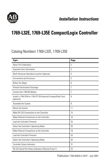
Installation Instructions<br />
<strong>1769</strong>-<strong>L32E</strong>, <strong>1769</strong>-<strong>L35E</strong> <strong>CompactLogix</strong> <strong>Controller</strong><br />
Catalog Numbers <strong>1769</strong>-<strong>L32E</strong>, <strong>1769</strong>-<strong>L35E</strong><br />
Topic Page<br />
About This Publication 2<br />
Important User Information 3<br />
North American Hazardous Location Approval 4<br />
Environment and Enclosure 5<br />
Before You Begin 6<br />
Prevent Electrostatic Discharge 7<br />
Connect the <strong>1769</strong>-BA Battery 7<br />
Install a 1784-CF64 or 1784-CF128 Industrial CompactFlash Card<br />
(optional)<br />
Assemble the System 9<br />
Mount the System 11<br />
Make RS-232 Connections to the <strong>Controller</strong> 15<br />
Make Ethernet Connections to the <strong>Controller</strong> 18<br />
Load the <strong>Controller</strong> Firmware 25<br />
Select the <strong>Controller</strong>’s Operating Mo<strong>de</strong> 30<br />
Make Ethernet Connections to the <strong>Controller</strong> 18<br />
Load the <strong>Controller</strong> Firmware 25<br />
Select the <strong>Controller</strong>’s Operating Mo<strong>de</strong> 30<br />
<strong>Controller</strong> Status Indicators 31<br />
RS-232 Serial Port Status Indicators (Channel 0 and 1) 33<br />
9<br />
Publication <strong>1769</strong>-IN020-C-EN-P - July 2007
2 <strong>1769</strong>-<strong>L32E</strong>, <strong>1769</strong>-<strong>L35E</strong> <strong>CompactLogix</strong> <strong>Controller</strong><br />
Topic Page<br />
CompactFlash Card Status Indicator 33<br />
Module Status (MS) indicator 34<br />
Additional Resources 39<br />
About This Publication<br />
Use this document as a gui<strong>de</strong> to install the <strong>CompactLogix</strong> controller.<br />
Publication <strong>1769</strong>-IN020-C-EN-P - July 2007
Important User Information<br />
<strong>1769</strong>-<strong>L32E</strong>, <strong>1769</strong>-<strong>L35E</strong> <strong>CompactLogix</strong> <strong>Controller</strong> 3<br />
Solid state equipment has operational characteristics differing from those of electromechanical<br />
equipment. Safety Gui<strong>de</strong>lines for the Application, Installation and Maintenance of Solid State Controls<br />
(publication SGI-1.1 available from your local Rockwell Automation sales office or online at<br />
http://literature.rockwellautomation.com) <strong>de</strong>scribes some important differences between solid state<br />
equipment and hard-wired electromechanical <strong>de</strong>vices. Because of this difference, and also because of<br />
the wi<strong>de</strong> variety of uses for solid state equipment, all persons responsible for applying this equipment<br />
must satisfy themselves that each inten<strong>de</strong>d application of this equipment is acceptable.<br />
In no event will Rockwell Automation, Inc. be responsible or liable for indirect or consequential damages<br />
resulting from the use or application of this equipment.<br />
The examples and diagrams in this manual are inclu<strong>de</strong>d solely for illustrative purposes. Because of the<br />
many variables and requirements associated with any particular installation, Rockwell Automation, Inc.<br />
cannot assume responsibility or liability for actual use based on the examples and diagrams.<br />
No patent liability is assumed by Rockwell Automation, Inc. with respect to use of information, circuits,<br />
equipment, or software <strong>de</strong>scribed in this manual.<br />
Reproduction of the contents of this manual, in whole or in part, without written permission of Rockwell<br />
Automation, Inc., is prohibited.<br />
Throughout this manual, when necessary, we use notes to make you aware of safety consi<strong>de</strong>rations.<br />
WARNING<br />
IMPORTANT<br />
ATTENTION<br />
SHOCK HAZARD<br />
BURN HAZARD<br />
I<strong>de</strong>ntifies information about practices or circumstances that can cause an explosion in<br />
a hazardous environment, which may lead to personal injury or <strong>de</strong>ath, property<br />
damage, or economic loss.<br />
I<strong>de</strong>ntifies information that is critical for successful application and un<strong>de</strong>rstanding of<br />
the product.<br />
I<strong>de</strong>ntifies information about practices or circumstances that can lead to personal<br />
injury or <strong>de</strong>ath, property damage, or economic loss. Attentions help you to i<strong>de</strong>ntify a<br />
hazard, avoid a hazard and recognize the consequences.<br />
Labels may be on or insi<strong>de</strong> the equipment, for example, a drive or motor, to alert<br />
people that dangerous voltage may be present.<br />
Labels may be on or insi<strong>de</strong> the equipment, for example, a drive or motor, to alert<br />
people that surfaces may reach dangerous temperatures.<br />
Publication <strong>1769</strong>-IN020-C-EN-P - July 2007
4 <strong>1769</strong>-<strong>L32E</strong>, <strong>1769</strong>-<strong>L35E</strong> <strong>CompactLogix</strong> <strong>Controller</strong><br />
North American Hazardous Location Approval<br />
The following information applies when<br />
operating this equipment in hazardous<br />
locations.<br />
Products marked “CL I, DIV 2, GP A, B, C, D” are<br />
suitable for use in Class I Division 2 Groups A, B,<br />
C, D, Hazardous Locations and nonhazardous<br />
locations only. Each product is supplied with<br />
markings on the rating nameplate indicating the<br />
hazardous location temperature co<strong>de</strong>. When<br />
combining products within a system, the most<br />
adverse temperature co<strong>de</strong> (lowest “T” number)<br />
may be used to help <strong>de</strong>termine the overall<br />
temperature co<strong>de</strong> of the system. Combinations<br />
of equipment in your system are subject to<br />
investigation by the local Authority Having<br />
Jurisdiction at the time of installation.<br />
WARNING<br />
EXPLOSION HAZARD<br />
Do not disconnect equipment<br />
unless power has been<br />
removed or the area is known<br />
to be nonhazardous.<br />
Do not disconnect<br />
connections to this<br />
equipment unless power has<br />
been removed or the area is<br />
known to be nonhazardous.<br />
Secure any external<br />
connections that mate to this<br />
equipment by using screws,<br />
sliding latches, threa<strong>de</strong>d<br />
connectors, or other means<br />
provi<strong>de</strong>d with this product.<br />
Substitution of components<br />
may impair suitability for<br />
Class I, Division 2.<br />
If this product contains<br />
batteries, they must only be<br />
changed in an area known to<br />
be nonhazardous.<br />
Publication <strong>1769</strong>-IN020-C-EN-P - July 2007<br />
Informations sur l'utilisation <strong>de</strong> cet équipement en<br />
environnements dangereux.<br />
Les produits marqués “CL I, DIV 2, GP A, B, C, D” ne<br />
conviennent qu'à une utilisation en environnements<br />
<strong>de</strong> Classe I Division 2 Groupes A, B, C, D dangereux<br />
et non dangereux. Chaque produit est livré avec <strong>de</strong>s<br />
marquages sur sa plaque d'i<strong>de</strong>ntification qui<br />
indiquent le co<strong>de</strong> <strong>de</strong> température pour les<br />
environnements dangereux. Lorsque plusieurs<br />
produits sont combinés dans un système, le co<strong>de</strong> <strong>de</strong><br />
température le plus défavorable (co<strong>de</strong> <strong>de</strong><br />
température le plus faible) peut être utilisé pour<br />
déterminer le co<strong>de</strong> <strong>de</strong> température global du<br />
système. Les combinaisons d'équipements dans le<br />
système sont sujettes à inspection par les autorités<br />
locales qualifiées au moment <strong>de</strong> l'installation.<br />
RISQUE D'EXPLOSION<br />
AVERTISSEMENT<br />
Couper le courant ou s'assurer<br />
que l'environnement est classé<br />
non dangereux avant <strong>de</strong><br />
débrancher l'équipement.<br />
Couper le courant ou s'assurer<br />
que l'environnement est classé<br />
non dangereux avant <strong>de</strong><br />
débrancher les connecteurs.<br />
Fixer tous les connecteurs<br />
externes reliés à cet<br />
équipement à l'ai<strong>de</strong> <strong>de</strong> vis,<br />
loquets coulissants,<br />
connecteurs filetés ou autres<br />
moyens fournis avec ce produit.<br />
La substitution <strong>de</strong> composants<br />
peut rendre cet équipement<br />
inadapté à une utilisation en<br />
environnement <strong>de</strong> Classe I,<br />
Division 2.<br />
S'assurer que l'environnement<br />
est classé non dangereux avant<br />
<strong>de</strong> changer les piles.
Environment and Enclosure<br />
ATTENTION<br />
<strong>1769</strong>-<strong>L32E</strong>, <strong>1769</strong>-<strong>L35E</strong> <strong>CompactLogix</strong> <strong>Controller</strong> 5<br />
This equipment is inten<strong>de</strong>d for use in a Pollution Degree 2 industrial environment, in<br />
overvoltage Category II applications (as <strong>de</strong>fined in IEC publication 60664-1), at altitu<strong>de</strong>s<br />
up to 2000 meters (6562 feet) without <strong>de</strong>rating.<br />
This equipment is consi<strong>de</strong>red Group 1, Class A industrial equipment according to<br />
IEC/CISPR Publication 11. Without appropriate precautions, there may be potential<br />
difficulties ensuring electromagnetic compatibility in other environments due to<br />
conducted as well as radiated disturbance.<br />
This equipment is supplied as open-type equipment. It must be mounted within an<br />
enclosure that is suitably <strong>de</strong>signed for those specific environmental conditions that will<br />
be present and appropriately <strong>de</strong>signed to prevent personal injury resulting from<br />
accessibility to live parts. The enclosure must have suitable flame-retardant properties to<br />
prevent or minimize the spread of flame, complying with a flame spread rating of 5VA, V2,<br />
V1, V0 (or equivalent) if non-metallic. The interior of the enclosure must be accessible only<br />
by the use of a tool. Subsequent sections of this publication may contain additional<br />
information regarding specific enclosure type ratings that are required to comply with<br />
certain product safety certifications.<br />
In addition to this publication, see:<br />
•Industrial Automation Wiring and Grounding Gui<strong>de</strong>lines, publication 1770-4.1, for<br />
additional installation requirements.<br />
•NEMA Standards publication 250 and IEC publication 60529, as applicable, for<br />
explanations of the <strong>de</strong>grees of protection provi<strong>de</strong>d by different types of enclosure.<br />
Publication <strong>1769</strong>-IN020-C-EN-P - July 2007
6 <strong>1769</strong>-<strong>L32E</strong>, <strong>1769</strong>-<strong>L35E</strong> <strong>CompactLogix</strong> <strong>Controller</strong><br />
Before You Begin<br />
Consi<strong>de</strong>r the following when planning your <strong>CompactLogix</strong> system:<br />
• The <strong>CompactLogix</strong> controller is always the leftmost module in<br />
the system.<br />
• The controller must be located within four modules of the<br />
system power supply. Some I/O modules may be located up<br />
to eight modules away from the power supply. See the<br />
documentation for your <strong>1769</strong> I/O modules for <strong>de</strong>tails.<br />
• The <strong>1769</strong>-<strong>L32E</strong> and <strong>1769</strong>-<strong>L35E</strong> controllers support as many as<br />
16 I/O modules in a maximum of 3 I/O banks with 2<br />
expansion cables.<br />
• Each I/O bank requires its own power supply.<br />
• Only one controller can be used in a <strong>CompactLogix</strong> system.<br />
• A <strong>1769</strong>-ECR right end cap or <strong>1769</strong>-ECL left end cap is required<br />
to terminate the end of the communication bus.<br />
Parts List<br />
These components ship with the controller.<br />
Component Description<br />
<strong>1769</strong>-BA battery<br />
You may also use these components with the controller.<br />
Publication <strong>1769</strong>-IN020-C-EN-P - July 2007<br />
Important: The <strong>1769</strong>-BA battery is the only battery you can use<br />
with the <strong>1769</strong>-<strong>L32E</strong> and <strong>1769</strong>-<strong>L35E</strong> controllers.<br />
1747-KY controller key<br />
If you want to Then use this component<br />
Connect a <strong>de</strong>vice to the RS_232 port 1756-CP3 or 1747-CP3 serial cable<br />
Connect a <strong>de</strong>vice to the EtherNet/IP port standard Ethernet cable with RJ-45 connector<br />
Add nonvolatile memory 1784-CF64 or 1784-CF128 Industrial CompactFlash card
Prevent Electrostatic Discharge<br />
<strong>1769</strong>-<strong>L32E</strong>, <strong>1769</strong>-<strong>L35E</strong> <strong>CompactLogix</strong> <strong>Controller</strong> 7<br />
Follow these gui<strong>de</strong>lines to prevent electrostatic damage.<br />
ATTENTION<br />
This equipment is sensitive to electrostatic discharge, which can cause internal<br />
damage and affect normal operation. Follow these gui<strong>de</strong>lines when you handle<br />
this equipment:<br />
•Touch a groun<strong>de</strong>d object to discharge potential static.<br />
•Wear an approved grounding wriststrap.<br />
•Do not touch connectors or pins on component boards.<br />
•Do not touch circuit components insi<strong>de</strong> the equipment.<br />
•Use a static-safe workstation, if available.<br />
•Store the equipment in appropriate static-safe packaging when not in use.<br />
Connect the <strong>1769</strong>-BA Battery<br />
The controller is shipped with the <strong>1769</strong>-BA battery packed separately.<br />
To connect the battery, follow this procedure.<br />
ATTENTION<br />
WARNING<br />
The <strong>1769</strong>-BA battery is the only battery you can use with the <strong>1769</strong>-<strong>L32E</strong> and <strong>1769</strong>-<strong>L35E</strong><br />
controllers. The 1747-BA battery is not compatible with the <strong>1769</strong>-<strong>L32E</strong> and <strong>1769</strong>-<strong>L35E</strong><br />
controllers and may cause problems.<br />
When you connect or disconnect the battery, an electrical arc can occur. This could cause<br />
an explosion in hazardous location installations. Be sure that power is removed or the area<br />
is nonhazardous before proceeding.<br />
For safety information on the handling of lithium batteries, including handling and<br />
disposal of leaking batteries, see Gui<strong>de</strong>lines for Handling Lithium Batteries Technical<br />
Data, publication AG-5.4NOV04.<br />
Publication <strong>1769</strong>-IN020-C-EN-P - July 2007
8 <strong>1769</strong>-<strong>L32E</strong>, <strong>1769</strong>-<strong>L35E</strong> <strong>CompactLogix</strong> <strong>Controller</strong><br />
1. Remove the battery door by sliding it forward.<br />
IMPORTANT<br />
Do not remove the plastic insulation covering the battery. The insulation is necessary<br />
to protect the battery contacts.<br />
2. Insert the battery connector into the connector port.<br />
The connector is keyed to be installed with the correct<br />
polarity.<br />
3. Insert the battery into the battery port in the battery door.<br />
4. Sli<strong>de</strong> the battery door back until it clicks into position.<br />
Publication <strong>1769</strong>-IN020-C-EN-P - July 2007<br />
Battery
<strong>1769</strong>-<strong>L32E</strong>, <strong>1769</strong>-<strong>L35E</strong> <strong>CompactLogix</strong> <strong>Controller</strong> 9<br />
Install a 1784-CF64 or 1784-CF128 Industrial CompactFlash Card<br />
(optional)<br />
ATTENTION<br />
The optional industrial CompactFlash card provi<strong>de</strong>s nonvolatile<br />
memory for a <strong>CompactLogix</strong> controller. The card is not required for<br />
controller operation.<br />
Follow this procedure to install the card.<br />
WARNING<br />
Do not remove the CompactFlash card while the controller is reading from or writing to<br />
the card, as indicated by a flashing green CF status indicator. This could corrupt the data<br />
on the card or in the controller, as well as corrupt the latest firmware in the controller.<br />
When you insert or remove the CompactFlash Card while power is on, an electrical arc can<br />
occur. This could cause an explosion in hazardous location installations.<br />
Be sure that power is removed or the area is nonhazardous before proceeding.<br />
1. Push the locking tab to the right and<br />
insert the industrial CompactFlash<br />
card into the socket on the front of<br />
the controller.<br />
The label of the CompactFlash card<br />
faces toward the left. Match the<br />
orientation arrow on the card with<br />
the arrow on the front of the<br />
controller.<br />
2. To remove the CompactFlash card,<br />
push the locking tab away from the<br />
CompactFlash card and pull the<br />
CompactFlash card from the socket.<br />
Assemble the System<br />
The controller can be attached to an adjacent I/O module or power<br />
supply before or after mounting. For mounting instructions, see<br />
Publication <strong>1769</strong>-IN020-C-EN-P - July 2007
10 <strong>1769</strong>-<strong>L32E</strong>, <strong>1769</strong>-<strong>L35E</strong> <strong>CompactLogix</strong> <strong>Controller</strong><br />
Grounding Consi<strong>de</strong>rations on page 12 or DIN Rail Mounting on page<br />
14.<br />
WARNING<br />
This procedure shows you how to install the controller in a<br />
<strong>CompactLogix</strong> system.<br />
A<br />
The <strong>CompactLogix</strong> controller is not <strong>de</strong>signed for removal and insertion un<strong>de</strong>r power.<br />
If you insert or remove the module while backplane power is on, an electrical arc can<br />
occur. This could cause an explosion in hazardous location installations.<br />
Be sure that power is removed or the area is nonhazardous before proceeding.<br />
1. Disconnect line power.<br />
2. Check that the lever of the adjacent module (A) is in the<br />
unlocked (fully right) position.<br />
3. Use the upper and lower tongue-and-groove slots (B) to<br />
secure the modules together.<br />
4. Move the module back along the tongue-and-groove slots<br />
until the bus connectors line up with each other.<br />
5. Use your fingers or a small screwdriver to push the module’s<br />
bus lever back slightly to clear the positioning tab (C).<br />
Publication <strong>1769</strong>-IN020-C-EN-P - July 2007<br />
B<br />
B<br />
C<br />
E<br />
D<br />
F
<strong>1769</strong>-<strong>L32E</strong>, <strong>1769</strong>-<strong>L35E</strong> <strong>CompactLogix</strong> <strong>Controller</strong> 11<br />
6. Move the module’s bus lever fully to the left (D) until it clicks,<br />
being sure it is locked firmly in place.<br />
ATTENTION<br />
7. Attach an end cap terminator (E) to the last module in the<br />
system by using the tongue-and-groove slots as before.<br />
8. Lock the end cap bus terminator (F).<br />
Mount the System<br />
ATTENTION<br />
Minimum Spacing<br />
When attaching the controller, power supply, and I/O modules, make sure the bus<br />
connectors are securely locked together to be sure of proper electrical connection.<br />
During panel or DIN rail mounting of all <strong>de</strong>vices, be sure that all <strong>de</strong>bris (such as metal<br />
chips or wire strands) is kept from falling into the controller. Debris that falls into the<br />
controller could cause damage while the controller is energized.<br />
Maintain spacing from enclosure walls, wireways, and adjacent<br />
equipment. Allow 50 mm (2 in.) of space on all si<strong>de</strong>s, as shown. This<br />
provi<strong>de</strong>s ventilation and electrical isolation.<br />
50 mm<br />
(1.97 in.)<br />
<strong>CompactLogix</strong><br />
<strong>Controller</strong><br />
Top<br />
Compact I/O<br />
Module<br />
Si<strong>de</strong> Si<strong>de</strong><br />
Bottom<br />
Power Supply<br />
50 mm<br />
(1.97 in.)<br />
Compact I/O<br />
Module<br />
End Cap<br />
50 mm (1.97 in.)<br />
50 mm<br />
(1.97 in.)<br />
Publication <strong>1769</strong>-IN020-C-EN-P - July 2007
12 <strong>1769</strong>-<strong>L32E</strong>, <strong>1769</strong>-<strong>L35E</strong> <strong>CompactLogix</strong> <strong>Controller</strong><br />
System Dimensions<br />
132 mm<br />
(5.20 in.)<br />
TIP<br />
Grounding Consi<strong>de</strong>rations<br />
ATTENTION<br />
15 mm<br />
(.59 in.)<br />
118 mm<br />
(4.65 in.)<br />
67.5 mm<br />
(2.68 in.)<br />
52.5 mm<br />
(2.06 in.)<br />
52.5 mm<br />
(2.07 in.)<br />
Compact I/O expansion cables have the same dimensions as the end caps. Expansion<br />
cables can be used on either the right or left end. A <strong>1769</strong>-ECR right end cap or <strong>1769</strong>-ECL<br />
left end cap terminates the end of the communication bus.<br />
This product is groun<strong>de</strong>d through the DIN rail to chassis ground. Use zinc plated<br />
yellow-chromate steel DIN rail to assure proper grounding. The use of other DIN rail<br />
materials (such as aluminum or plastic) that can corro<strong>de</strong>, oxidize, or are poor conductors,<br />
can result in improper or intermittent grounding. Secure DIN rail to mounting surface<br />
approximately every 200 mm (7.8 in.) and use end-anchors appropriately.<br />
This product is inten<strong>de</strong>d to be mounted to a well-groun<strong>de</strong>d mounting<br />
surface such as a metal panel. Additional grounding connections from<br />
the controller’s mounting tabs or DIN rail (if used) are not required<br />
unless the mounting surface cannot be groun<strong>de</strong>d.<br />
Refer to publication 1770-4.1, Industrial Automation Wiring and<br />
Grounding Gui<strong>de</strong>lines, for additional information.<br />
Publication <strong>1769</strong>-IN020-C-EN-P - July 2007<br />
70 mm<br />
(2.76 in.)<br />
35 mm<br />
(1.38 in.)<br />
35 mm<br />
(1.38 in.)<br />
35 mm<br />
(1.38 in.)<br />
35 mm<br />
(1.38 in.)<br />
35 mm<br />
(1.38 in.)
Panel Mounting<br />
<strong>1769</strong>-<strong>L32E</strong>, <strong>1769</strong>-<strong>L35E</strong> <strong>CompactLogix</strong> <strong>Controller</strong> 13<br />
Mount the controller to a panel by using two screws per module. Use<br />
M4 or #8 panhead screws. Mounting screws are required on every<br />
module.<br />
This procedure lets you use the assembled modules as a template for<br />
drilling holes in the panel.<br />
IMPORTANT Due to module mounting hole tolerance, it is important to follow these procedures.<br />
1. On a clean work surface, assemble no more than three<br />
modules.<br />
2. Using the assembled modules as a template, carefully mark the<br />
center of all module-mounting holes on the panel.<br />
3. Return the assembled modules to the clean work surface,<br />
including any previously mounted modules.<br />
4. Drill and tap the mounting holes for the recommen<strong>de</strong>d M4 or<br />
#8 screw.<br />
5. Place the modules back on the panel and check for proper<br />
hole alignment.<br />
TIP<br />
The grounding plate, located where the you install the mounting screws, enables the<br />
module to be groun<strong>de</strong>d when it is panel-mounted.<br />
Publication <strong>1769</strong>-IN020-C-EN-P - July 2007
14 <strong>1769</strong>-<strong>L32E</strong>, <strong>1769</strong>-<strong>L35E</strong> <strong>CompactLogix</strong> <strong>Controller</strong><br />
6. Attach the modules to the panel by using the mounting<br />
screws.<br />
TIP<br />
7. Repeat steps 1...6 for any remaining modules.<br />
DIN Rail Mounting<br />
The controller can be mounted on the following DIN rails:<br />
• EN 50 022 - 35 x 7.5 mm (1.38 x 0.30 in.)<br />
• EN 50 022 - 35 x 15 mm (1.38 x 0.59 in.)<br />
ATTENTION<br />
If you are mounting more modules, mount only the last one of this group and put the<br />
others asi<strong>de</strong>. This reduces remounting time when you are drilling and tapping the next<br />
group of modules.<br />
This product is groun<strong>de</strong>d through the DIN rail to chassis ground. Use zinc plated<br />
yellow-chromate steel DIN rail to assure proper grounding. The use of other DIN rail<br />
materials (for example, aluminum or plastic) that can corro<strong>de</strong>, oxidize, or are poor<br />
conductors, can result in improper or intermittent grounding. Secure DIN rail to mounting<br />
surface approximately every 200 mm (7.8 in.) and use end-anchors appropriately.<br />
1. Before mounting the controller on a DIN rail, close the DIN<br />
rail latches.<br />
2. Press the DIN rail mounting area of the controller against the<br />
DIN rail.<br />
The latches will momentarily open and lock into place.<br />
Publication <strong>1769</strong>-IN020-C-EN-P - July 2007
Make RS-232 Connections to the <strong>Controller</strong><br />
<strong>1769</strong>-<strong>L32E</strong>, <strong>1769</strong>-<strong>L35E</strong> <strong>CompactLogix</strong> <strong>Controller</strong> 15<br />
Connect the 9-pin female end of the serial cable to the serial port of<br />
the controller.<br />
WARNING<br />
RS-232 Cable<br />
If you connect or disconnect the serial cable with power applied to this module or the<br />
serial <strong>de</strong>vice on the other end of the cable, an electrical arc can occur. This could cause<br />
an explosion in hazardous location installations.<br />
Be sure that power is removed or the area is nonhazardous before proceeding.<br />
9-pin, Male D-shell Straight<br />
Cable End<br />
9-pin, Female D-shell<br />
Right-angle Cable End<br />
1747-CP3 or 1756-CP3<br />
This cable must be shiel<strong>de</strong>d and tied to<br />
the connector housing.<br />
1 CD<br />
2 RDX<br />
3 TXD<br />
4 DTR<br />
COMMON<br />
6 DSR<br />
7 RTS<br />
8 CTS<br />
9<br />
Straight Cable End<br />
1 CD<br />
2 RDX<br />
3 TXD<br />
4 DTR<br />
COMMON<br />
6 DSR<br />
7 RTS<br />
8 CTS<br />
9<br />
Right-angle Cable End<br />
Publication <strong>1769</strong>-IN020-C-EN-P - July 2007
16 <strong>1769</strong>-<strong>L32E</strong>, <strong>1769</strong>-<strong>L35E</strong> <strong>CompactLogix</strong> <strong>Controller</strong><br />
Default Serial Configuration<br />
Channel 0 and Channel 1 (both serial ports) have the following<br />
<strong>de</strong>fault communication configuration.<br />
Parameter Default<br />
Protocol DF1 full-duplex<br />
Communication Rate 19.2 Kbps<br />
Parity None<br />
Station Address 0<br />
Control Lines No Handshaking<br />
Error Detection BCC<br />
Embed<strong>de</strong>d Responses Auto Detect<br />
Duplicate Packet (Message) Detect Enabled<br />
ACK Timeout 50 (x 20 ms)<br />
NAK Receive Limit 3 Retries<br />
ENQ Transmit Limit 3 Retries<br />
Data Bits 8<br />
Stop Bits 1<br />
TIP Only Channel 0 has a <strong>de</strong>fault communication push button (see page 17).<br />
Publication <strong>1769</strong>-IN020-C-EN-P - July 2007
<strong>1769</strong>-<strong>L32E</strong>, <strong>1769</strong>-<strong>L35E</strong> <strong>CompactLogix</strong> <strong>Controller</strong> 17<br />
Using the Channel 0 Default Communication Push Button<br />
The Channel 0 <strong>de</strong>fault communication<br />
push button is located on the front of the<br />
controller in the lower right corner as<br />
shown in the illustration.<br />
Use the Channel 0 <strong>de</strong>fault<br />
communication push button to change<br />
from the user-<strong>de</strong>fined communication<br />
configuration to the <strong>de</strong>fault<br />
communication mo<strong>de</strong>. The Channel 0<br />
<strong>de</strong>fault communication (DCH0) status<br />
indicator turns on (green, steady) to indicate that the <strong>de</strong>fault<br />
communication configuration is active.<br />
TIP<br />
The <strong>de</strong>fault communication push button is recessed.<br />
Before pressing the <strong>de</strong>fault communication push button, be sure to note the present<br />
communication configuration for Channel 0. Pushing the <strong>de</strong>fault communication push<br />
button resets all configured parameters back to their <strong>de</strong>fault settings.<br />
To return the channel to its user-configured parameters, you must enter them manually<br />
while online with the controller or download them as part of an RSLogix 5000 software<br />
project file. To do this online with RSLogix 5000 software, access the <strong>Controller</strong><br />
Properties dialog and enter parameters on the Serial Port, System Protocol, and User<br />
Protocol tabs.<br />
Publication <strong>1769</strong>-IN020-C-EN-P - July 2007
18 <strong>1769</strong>-<strong>L32E</strong>, <strong>1769</strong>-<strong>L35E</strong> <strong>CompactLogix</strong> <strong>Controller</strong><br />
Make Ethernet Connections to the <strong>Controller</strong><br />
The <strong>1769</strong>-<strong>L32E</strong> and <strong>1769</strong>-<strong>L35E</strong> controllers ship with the BOOTP utility<br />
enabled. You must assign an IP address to the Ethernet port in or<strong>de</strong>r<br />
for the controller to communicate over an EtherNet/IP network.<br />
WARNING<br />
Connect the RJ-45 connector of the Ethernet cable to the Ethernet<br />
port (top port, CH1) on the controller.<br />
ATTENTION<br />
If you connect or disconnect the communications cable with power applied to this module<br />
or any <strong>de</strong>vice on the network, an electrical arc can occur. This could cause an explosion in<br />
hazardous location installations.<br />
Be sure that power is removed or the area is nonhazardous before proceeding.<br />
Do not plug a DH-485 network cable or a NAP port cable into the Ethernet port.<br />
Un<strong>de</strong>sirable behavior and/or damage to the port may result.<br />
Publication <strong>1769</strong>-IN020-C-EN-P - July 2007<br />
8 ------ NC<br />
7 ------ NC<br />
6 ------ RD-<br />
5 ------ NC<br />
4 ------ NC<br />
3 ------ RD+<br />
2 ------ TD-<br />
1 ------ TD+
Assigning an IP address<br />
<strong>1769</strong>-<strong>L32E</strong>, <strong>1769</strong>-<strong>L35E</strong> <strong>CompactLogix</strong> <strong>Controller</strong> 19<br />
You can set the IP address using any of these utilities:<br />
• Rockwell BOOTP Utility (available with RSLinx and RSLogix<br />
5000 software)<br />
• RSLinx software<br />
• RSLogix 5000 software<br />
Use BOOTP to set the IP address<br />
The BOOTP utility is a standalone program that is located in one of<br />
the following directories:<br />
• RSLinx Tools directory in the Rockwell Software program<br />
fol<strong>de</strong>r on the Start menu (the utility is automatically installed<br />
when you install RSLinx software)<br />
• Utils directory on the RSLogix 5000 software installation CD<br />
Follow this procedure to use the BOOTP utility.<br />
1. Start the BOOTP software.<br />
2. Select Tools>Network Settings.<br />
3. Enter the Ethernet mask and gateway.<br />
4. Click Ok.<br />
Publication <strong>1769</strong>-IN020-C-EN-P - July 2007
20 <strong>1769</strong>-<strong>L32E</strong>, <strong>1769</strong>-<strong>L35E</strong> <strong>CompactLogix</strong> <strong>Controller</strong><br />
In the BOOTP Request History dialog you see the hardware<br />
addresses of <strong>de</strong>vices issuing BOOTP requests.<br />
5. Double-click on the hardware address of the <strong>de</strong>vice you want<br />
to configure.<br />
TIP<br />
The hardware address is on the sticker located on the left-si<strong>de</strong> circuit board of the<br />
controller next to the battery. See Connect the <strong>1769</strong>-BA Battery on page 7 for<br />
instructions on accessing this area.<br />
The hardware address will be in this format: 00-0b-db-14-55-35.<br />
The New Entry dialog displays the <strong>de</strong>vice’s Ethernet Address<br />
(MAC).<br />
6. Enter the IP address.<br />
Publication <strong>1769</strong>-IN020-C-EN-P - July 2007
7. Click Ok.<br />
<strong>1769</strong>-<strong>L32E</strong>, <strong>1769</strong>-<strong>L35E</strong> <strong>CompactLogix</strong> <strong>Controller</strong> 21<br />
8. To permanently assign this configuration to the <strong>de</strong>vice,<br />
highlight the <strong>de</strong>vice and click Disable BOOTP/DHCP.<br />
When power is recycled, the <strong>de</strong>vice uses the configuration you<br />
assigned and does not issue a BootP request.<br />
Use RSLinx software to set the IP address<br />
You can use RSLinx software, version 2.41 or later, to set the IP<br />
address.<br />
1. Make sure the controller that uses the IP address is installed<br />
and running.<br />
2. Connect to the controller via the serial connection (see page<br />
15).<br />
3. Start RSLinx software.<br />
The RSWho dialog opens.<br />
4. Navigate to the Ethernet network.<br />
Publication <strong>1769</strong>-IN020-C-EN-P - July 2007
22 <strong>1769</strong>-<strong>L32E</strong>, <strong>1769</strong>-<strong>L35E</strong> <strong>CompactLogix</strong> <strong>Controller</strong><br />
5. Right-click the Ethernet port (not the controller) and select<br />
Module Configuration<br />
6. Select the Port Configuration tab.<br />
Publication <strong>1769</strong>-IN020-C-EN-P - July 2007
<strong>1769</strong>-<strong>L32E</strong>, <strong>1769</strong>-<strong>L35E</strong> <strong>CompactLogix</strong> <strong>Controller</strong> 23<br />
7. Click the appropriate radio button to choose the Status<br />
Network Configuration type.<br />
8. Enter the IP address, network (subnet) mask, and gateway<br />
address (if nee<strong>de</strong>d).<br />
Use RSLogix 5000 software to set the IP address<br />
You can use RSLogix software to set the IP address.<br />
1. Make sure the controller that uses the IP address is installed<br />
and running.<br />
2. Connect to the controller via the serial connection (see page<br />
15).<br />
Publication <strong>1769</strong>-IN020-C-EN-P - July 2007
24 <strong>1769</strong>-<strong>L32E</strong>, <strong>1769</strong>-<strong>L35E</strong> <strong>CompactLogix</strong> <strong>Controller</strong><br />
3. Start RSLogix 5000 software. In the <strong>Controller</strong> Organizer, select<br />
properties for the Ethernet port.<br />
4. Choose the Port Configuration tab.<br />
5. Specify the IP address.<br />
6. Click Apply.<br />
7. Click Ok.<br />
This sets the IP address in the hardware. This IP address<br />
should be the same IP address you assigned un<strong>de</strong>r the<br />
General tab.<br />
Publication <strong>1769</strong>-IN020-C-EN-P - July 2007
Install the Appropriate EDS Files<br />
<strong>1769</strong>-<strong>L32E</strong>, <strong>1769</strong>-<strong>L35E</strong> <strong>CompactLogix</strong> <strong>Controller</strong> 25<br />
If you have RSLinx software, version 2.42 or later, the most current<br />
EDS files were installed with the software. If you are using an earlier<br />
version of RSLinx software, you might need to install EDS files.<br />
You need EDS files for these <strong>de</strong>vices:<br />
• <strong>1769</strong>-<strong>L32E</strong> and <strong>1769</strong>-<strong>L35E</strong> controllers<br />
• <strong>1769</strong> CompactBus<br />
• <strong>1769</strong> local adapter<br />
All of these EDS files, except for the <strong>1769</strong> CompactBus file, are<br />
updated for each firmware revision. There is also a version 1 of the<br />
controller EDS file that you need for new controllers. Each controller<br />
ships with revision 1 firmware. In or<strong>de</strong>r to update the firmware, you<br />
must have the revision 1 EDS file (0001000E00410100.eds) installed<br />
for the controller.<br />
The EDS files are available on the RSLogix 5000 Enterprise Series<br />
software CD. The files are also available at<br />
http://www.ab.com/networks/eds.<br />
Load the <strong>Controller</strong> Firmware<br />
You must download the current firmware before you can use the<br />
controller.<br />
To load firmware, you can use any of the following:<br />
• ControlFlash utility that ships with RSLogix 5000 programming<br />
software.<br />
• AutoFlash that launches through RSLogix 5000 software when<br />
you try to open or create a project and the controller does not<br />
have the current firmware.<br />
• A CompactFlash card (catalog number 1784-CF64 or<br />
1784-CF128) with valid memory already loa<strong>de</strong>d.<br />
If you use the ControlFlash or AutoFlash utilities, you need a serial<br />
connection to the controller.<br />
Publication <strong>1769</strong>-IN020-C-EN-P - July 2007
26 <strong>1769</strong>-<strong>L32E</strong>, <strong>1769</strong>-<strong>L35E</strong> <strong>CompactLogix</strong> <strong>Controller</strong><br />
The firmware is available with RSLogix 5000 software or you can<br />
download it from the support website. Go to<br />
http://support.rockwellautomation.com.<br />
Follow these steps to download firmware from the support website.<br />
1. In the left column (frame), click Technical Support.<br />
2. Click Firmware Updates.<br />
3. Select the firmware revision.<br />
4. Enter the serial number of your RSLogix 5000 programming<br />
software.<br />
Publication <strong>1769</strong>-IN020-C-EN-P - July 2007
Use the ControlFlash Utility to Load Firmware<br />
<strong>1769</strong>-<strong>L32E</strong>, <strong>1769</strong>-<strong>L35E</strong> <strong>CompactLogix</strong> <strong>Controller</strong> 27<br />
You can use the ControlFlash utility to load firmware through a serial<br />
connection.<br />
1. Make sure the appropriate network connection is ma<strong>de</strong> before<br />
starting.<br />
2. Start the ControlFlash utility.<br />
3. When the Welcome dialog appears, click Next.<br />
4. Choose the catalog number of the controller and click Next.<br />
5. Expand the network until you see the controller.<br />
6. If the required network is not shown, first configure a driver<br />
for the network in RSLinx software.<br />
7. Choose the controller and click Ok.<br />
8. Choose the revision level to which you want to update the<br />
controller and click Next.<br />
9. To start the update of the controller, click Finish and then click<br />
Yes.<br />
10. After the controller is updated, the status dialog displays<br />
Update complete.<br />
11. Click Ok.<br />
12. To close the ControlFlash utility, click Cancel and then click<br />
Yes.<br />
Publication <strong>1769</strong>-IN020-C-EN-P - July 2007
28 <strong>1769</strong>-<strong>L32E</strong>, <strong>1769</strong>-<strong>L35E</strong> <strong>CompactLogix</strong> <strong>Controller</strong><br />
Use AutoFlash to Load Firmware<br />
You can use AutoFlash to load firmware through a serial connection.<br />
1. Make sure the appropriate network connection is ma<strong>de</strong> before<br />
starting.<br />
2. Use RSLogix 5000 programming software to create a controller<br />
project.<br />
This automatically launches AutoFlash.<br />
3. Choose the catalog number of the controller and click Next.<br />
4. Expand the network until you see the controller.<br />
If the required network is not shown, first configure a driver<br />
for the network in RSLinx software.<br />
5. Choose the controller and click Ok.<br />
6. Choose the revision level to which you want to update the<br />
controller and click Next.<br />
7. To start the update of the controller, click Finish and then click<br />
Yes.<br />
After the controller is updated, the status dialog displays<br />
Update complete.<br />
8. Click Ok.<br />
9. To close the AutoFlash utility, click Cancel and then click Yes.<br />
Publication <strong>1769</strong>-IN020-C-EN-P - July 2007
Use a CompactFlash Card to Load Firmware<br />
<strong>1769</strong>-<strong>L32E</strong>, <strong>1769</strong>-<strong>L35E</strong> <strong>CompactLogix</strong> <strong>Controller</strong> 29<br />
If you have an existing controller that is already configured and has<br />
firmware loa<strong>de</strong>d, you can store the current controller user program<br />
and firmware on the CompactFlash card and use that card to update<br />
other controllers.<br />
1. Use RSLogix 5000 software to store the controller user<br />
program and firmware of a currently configured controller to<br />
the CompactFlash card.<br />
2. Access the Nonvolatile Memory tab of the <strong>Controller</strong><br />
Properties dialog.<br />
Be sure to select Load Image On Powerup when you save to<br />
the card.<br />
3. Remove the card and insert it into a controller that will use the<br />
same firmware and controller user program.<br />
When you apply power to the second controller, the image<br />
stored on the CompactFlash card is loa<strong>de</strong>d into the controller.<br />
Publication <strong>1769</strong>-IN020-C-EN-P - July 2007
30 <strong>1769</strong>-<strong>L32E</strong>, <strong>1769</strong>-<strong>L35E</strong> <strong>CompactLogix</strong> <strong>Controller</strong><br />
Select the <strong>Controller</strong>’s Operating Mo<strong>de</strong><br />
Use the keyswitch on the front panel of the controller to <strong>de</strong>termine<br />
the controller’s operating mo<strong>de</strong>.<br />
Keyswitch<br />
Position<br />
Description<br />
Run •Upload projects.<br />
•Run the program and enable outputs.<br />
•You cannot create or <strong>de</strong>lete tasks, programs, or routines. You cannot create or<br />
<strong>de</strong>lete tags or edit online while the keyswitch is in the Run position.<br />
•You cannot change the mo<strong>de</strong> by using the programming software while the<br />
keyswitch is in the Run position.<br />
Prog •Disable outputs.<br />
•Upload/download projects.<br />
•Create, modify, and <strong>de</strong>lete tasks, programs, or routines.<br />
•The controller does not execute (scan) tasks while the keyswitch is in the Prog<br />
position.<br />
•You cannot change the mo<strong>de</strong> through the programming software while the<br />
keyswitch is in the Prog position.<br />
Rem •Upload/download projects.<br />
•Change between Remote Program, Remote Test, and Remote Run mo<strong>de</strong>s through<br />
the programming software.<br />
Remote Run •The controller executes (scans) tasks.<br />
•Enable outputs.<br />
•Edit online.<br />
Remote Program •Disable outputs.<br />
•Create, modify, and <strong>de</strong>lete tasks, programs or routines.<br />
•Download projects.<br />
•Edit online.<br />
•The controller does not execute (scan) tasks.<br />
Remote Test •Execute tasks with outputs disabled.<br />
•Edit online.<br />
Publication <strong>1769</strong>-IN020-C-EN-P - July 2007
<strong>Controller</strong> Status Indicators<br />
Indicator Status Description<br />
<strong>1769</strong>-<strong>L32E</strong>, <strong>1769</strong>-<strong>L35E</strong> <strong>CompactLogix</strong> <strong>Controller</strong> 31<br />
RUN Off The controller is in Program or Test mo<strong>de</strong>.<br />
Solid green The controller is in Run mo<strong>de</strong>.<br />
FORCE Off •No tags contain I/O force values.<br />
•I/O forces are inactive (disabled).<br />
Solid amber •I/O forces are active (enabled).<br />
•I/O force values may or may not exist.<br />
Flashing amber One or more input or output addresses have been forced to an On<br />
or Off state, but the forces have not been enabled.<br />
BAT Off The battery supports memory.<br />
Solid red Either the battery is:<br />
•not installed.<br />
•95% discharged and should be replaced.<br />
I/O Off Either:<br />
•There are no <strong>de</strong>vices in the I/O configuration of the<br />
controller.<br />
•The controller does not contain a project (controller memory<br />
is empty).<br />
Solid green The controller is communicating with all the <strong>de</strong>vices in its I/O<br />
configuration.<br />
Flashing green One or more <strong>de</strong>vices in the I/O configuration of the controller are<br />
not responding.<br />
Flashing red •The controller is not communicating to any <strong>de</strong>vices.<br />
•The controller is faulted.<br />
Publication <strong>1769</strong>-IN020-C-EN-P - July 2007
32 <strong>1769</strong>-<strong>L32E</strong>, <strong>1769</strong>-<strong>L35E</strong> <strong>CompactLogix</strong> <strong>Controller</strong><br />
Indicator Status Description<br />
OK Off No power is applied.<br />
Flashing red If the controller is new, the controller requires a firmware update.<br />
If the controller is not new, a major fault occurred.<br />
To clear the fault, do one of the following:<br />
Publication <strong>1769</strong>-IN020-C-EN-P - July 2007<br />
•Turn the keyswitch from Prog to Run to Prog.<br />
•Go online with RSLogix 5000 software.<br />
Solid red The controller <strong>de</strong>tected a nonrecoverable fault, so it cleared the<br />
project from memory. Follow these steps to recover.<br />
1. Cycle power to the chassis.<br />
2. Download the project.<br />
3. Change to Run mo<strong>de</strong>.<br />
If the OK status indicator remains solid red, contact your<br />
Rockwell Automation representative or local distributor.<br />
Solid green <strong>Controller</strong> is OK.<br />
Flashing green The controller is storing or loading a project to or from<br />
nonvolatile memory.
<strong>1769</strong>-<strong>L32E</strong>, <strong>1769</strong>-<strong>L35E</strong> <strong>CompactLogix</strong> <strong>Controller</strong> 33<br />
RS-232 Serial Port Status Indicators (Channel 0 and 1)<br />
Indicator Status Description<br />
DCH0 Off Channel 0 is configured differently than the <strong>de</strong>fault serial<br />
configuration.<br />
Solid green Channel 0 has the <strong>de</strong>fault serial configuration.<br />
CH0 Off No RS-232 activity.<br />
Flashing green RS-232 activity.<br />
CH1 Off No RS-232 activity.<br />
CompactFlash Card Status Indicator<br />
ATTENTION<br />
Flashing green RS-232 activity.<br />
Do not remove the CompactFlash card while the controller is reading from or writing to<br />
the card, as indicated by a flashing green CF status indicator. This could corrupt the data<br />
on the card or in the controller, as well as corrupt the latest firmware in the controller.<br />
Indicator Status Description<br />
CF Off No activity.<br />
Flashing green The controller is reading from or writing to the CompactFlash<br />
card.<br />
Flashing red CompactFlash card does not have a valid file system.<br />
Publication <strong>1769</strong>-IN020-C-EN-P - July 2007
34 <strong>1769</strong>-<strong>L32E</strong>, <strong>1769</strong>-<strong>L35E</strong> <strong>CompactLogix</strong> <strong>Controller</strong><br />
Module Status (MS) indicator<br />
Condition Status Indicates Recommen<strong>de</strong>d Action<br />
Off No power The controller does not have<br />
power.<br />
Flashing green Standby The port does not have an IP<br />
address and is operating in<br />
BOOTP mo<strong>de</strong>.<br />
Solid green Ok The port is operating<br />
correctly.<br />
Solid red Held in reset The controller is holding the<br />
port in reset or the controller<br />
is faulted.<br />
Flashing red Updating<br />
firmware<br />
Self-test The port is performing its<br />
power-up self-test.<br />
Major fault An unrecoverable fault has<br />
occurred.<br />
Publication <strong>1769</strong>-IN020-C-EN-P - July 2007<br />
The port firmware is being<br />
updated.<br />
Check the controller power supply.<br />
Verify that the BOOTP server is<br />
running.<br />
Normal operation. No action<br />
required.<br />
Clear the controller fault.<br />
Replace the controller.<br />
Normal operation during<br />
power-up. No action required.<br />
Cycle power to the controller.<br />
Replace the controller.<br />
Normal operation during firmware<br />
update. No action required.
Network Status (NS) indicator<br />
Link Status (LNK) indicator<br />
<strong>1769</strong>-<strong>L32E</strong>, <strong>1769</strong>-<strong>L35E</strong> <strong>CompactLogix</strong> <strong>Controller</strong> 35<br />
Condition Status Indicates Recommen<strong>de</strong>d Action<br />
Off Not initialized The port does not have an IP<br />
address and is operating in<br />
BOOTP mo<strong>de</strong>.<br />
Flashing green No CIP<br />
connections<br />
established<br />
Solid green CIP<br />
connections<br />
established<br />
Solid red Duplicate IP<br />
address<br />
Flashing<br />
Red/green<br />
The port has an IP address,<br />
but no CIP connections are<br />
established.<br />
The port has an IP address<br />
and CIP connections (Class 1<br />
or Class 3) are established.<br />
The port has <strong>de</strong>tected that<br />
the assigned IP address is<br />
already in use.<br />
Self-test The port is performing its<br />
power-up self-test.<br />
Verify that the BOOTP server is<br />
running.<br />
Normal operation if no<br />
connections are configured. No<br />
action required.<br />
If connections are configured,<br />
check connection originator for<br />
connection error co<strong>de</strong>.<br />
Normal operation. No action<br />
required.<br />
Verify that all IP addresses are<br />
unique.<br />
Normal operation during powerup.<br />
Condition Status Indicates Recommen<strong>de</strong>d Action<br />
Off No link The port is not connected to<br />
a powered Ethernet <strong>de</strong>vice.<br />
The port cannot<br />
communicate on Ethernet.<br />
Flashing green Self-test The port is performing its<br />
power-up self-test.<br />
Data<br />
transmission<br />
and reception<br />
The port is communicating<br />
on Ethernet.<br />
Solid green Link Ok The port is connected to a<br />
powered Ethernet <strong>de</strong>vice.<br />
The port can communicate<br />
on Ethernet.<br />
•Verify that all Ethernet cables<br />
are connected.<br />
•Verify that Ethernet switch is<br />
powered.<br />
Normal operation during powerup.<br />
Normal operation. No action<br />
required.<br />
Normal operation. No action<br />
required.<br />
Publication <strong>1769</strong>-IN020-C-EN-P - July 2007
36 <strong>1769</strong>-<strong>L32E</strong>, <strong>1769</strong>-<strong>L35E</strong> <strong>CompactLogix</strong> <strong>Controller</strong><br />
Specifications<br />
<strong>CompactLogix</strong> <strong>Controller</strong> - <strong>1769</strong>-<strong>L32E</strong>, <strong>1769</strong>-<strong>L35E</strong><br />
Attribute Value<br />
Communication ports CH0 - RS-232 CH1 - RS-232<br />
RS-232 RS-232<br />
DF1, DH-485, ASCII DF1, DH-485<br />
fully isolated non-isolated<br />
38.4 Kbps max 38.4 Kbps max<br />
User memory 512 KB<br />
Nonvolatile memory 1784-CF64 or 1784-CF128 CompactFlash card<br />
Number of I/O modules, max 16 I/O modules<br />
Number of I/O banks, max 3 banks<br />
Backplane current 330 mA at 5V dc<br />
40 mA at 24V dc<br />
Power dissipation 2.61 W<br />
Power supply distance rating 4 (The controller must be within four slot positions of the power<br />
supply.)<br />
North American temp co<strong>de</strong> T4A<br />
Battery <strong>1769</strong>-BA<br />
Weight, approx. 0.30 kg (0.66 lb)<br />
Programming cable 1747-CP3 or 1756-CP3<br />
Panel mounting screw torque<br />
(using M4 or #8 screws)<br />
10...16 in-lb. (1.1...1.8 Nm)<br />
Enclosure type rating none (open style)<br />
Wiring category 2 on communication ports (1)<br />
Isolation voltage 30V (continuous), Basic Insulation Type<br />
Type tested at 710V dc for 60 s, RS232 to system, ENET to system,<br />
RS232 to ENET<br />
(1) Use this Conductor Category information for planning conductor routing. See Industrial Automation<br />
Wiring and Grounding Gui<strong>de</strong>lines, publication 1770-4.1.<br />
Publication <strong>1769</strong>-IN020-C-EN-P - July 2007
Environmental Specifications<br />
Attribute Value<br />
Operational temperature<br />
IEC 60068-2-1 (Test Ad, Operating Cold)<br />
IEC 60068-2-2 (Test Bd, Operating Dry Heat)<br />
IEC 60068-2-14 (Test Nb, Operating Thermal Shock)<br />
Storage temperature<br />
IEC 60068-2-1 (Test Ab, Unpackaged Nonoperating<br />
Cold)<br />
IEC 60068-2-2 (Test Bb, Unpackaged Nonoperating<br />
Dry Heat)<br />
IEC 60068-2-14 (Test Na, Unpackaged Thermal<br />
Shock)<br />
Relative humidity<br />
IEC 60068-2-30 (Test Db, Unpackaged)<br />
Vibration<br />
IEC 60068-2-6 (Test Fc, Operating)<br />
Shock<br />
IEC 60068-2-27 (Test Ea, Unpackaged Shock)<br />
DIN rail mount<br />
Panel mount<br />
<strong>1769</strong>-<strong>L32E</strong>, <strong>1769</strong>-<strong>L35E</strong> <strong>CompactLogix</strong> <strong>Controller</strong> 37<br />
0...60 °C (32...+140 °F)<br />
-40... +85 °C (-40...+185 °F)<br />
5...95% non-con<strong>de</strong>nsing<br />
Operating: 5 g @ 10...500 Hz<br />
Emissions (CISPR 11) Group 1, Class A<br />
Operating: 20 g; Nonoperating: 30 g<br />
Operating: 30 g; Nonoperating: 40 g<br />
ESD immunity (IEC61000-4-2) 6 kV contact discharges, 8 kV air discharges<br />
Radiated RF immunity<br />
IEC61000-4-3<br />
10V/m with 1 kHz sine-wave 80%AM from<br />
80…2000 MHz<br />
10V/m with 200 Hz 50% Pulse 100%AM at<br />
900 MHz<br />
10V/m with 200 Hz 50% Pulse 100%AM at<br />
1890 MHz<br />
3V/m with 1 kHz sine-wave 80%AM from<br />
2000…2700 MHz<br />
EFT/B immunity (IEC 61000-4-4) +2 kV at 5 kHz on communication ports<br />
Surge transient immunity (IEC61000-4-5) ±2 kV line-earth(CM) on communication ports<br />
Conducted RF immunity (IEC61000-4-6) 10V rms with 1kHz sine-wave 80% AM from<br />
150 kHz...80 MHz<br />
Publication <strong>1769</strong>-IN020-C-EN-P - July 2007
38 <strong>1769</strong>-<strong>L32E</strong>, <strong>1769</strong>-<strong>L35E</strong> <strong>CompactLogix</strong> <strong>Controller</strong><br />
Certifications<br />
Certifications (1)<br />
(when product is marked)<br />
Value<br />
c-UL-us UL Listed Industrial Control Equipment, certified for US and<br />
Canada. See UL File E65584.<br />
Publication <strong>1769</strong>-IN020-C-EN-P - July 2007<br />
UL Listed for Class I, Division 2 Group A,B,C,D Hazardous Locations,<br />
certified for U.S. and Canada. See UL File E194810.<br />
CE European Union 89/336/EEC EMC Directive, compliant with:<br />
• EN 50082-2; Industrial Immunity<br />
• EN 61326; Meas./Control/Lab., Industrial Requirements<br />
• EN 61000-6-2; Industrial Immunity<br />
• EN 61000-6-4; Industrial Emissions<br />
• EN 61131-2; Programmable <strong>Controller</strong>s (Clause 8, Zone<br />
A & B)<br />
C-Tick Australian Radio Communications Act, compliant with:<br />
• AS/NZS CISPR 11; Industrial Emissions<br />
EtherNet/IP ODVA conformance tested to EtherNet/IP specifications.<br />
(1) See the Product Certification link at http://www.ab.com for Declarations of Conformity, Certificates,<br />
and other certification <strong>de</strong>tails.
Additional Resources<br />
<strong>1769</strong>-<strong>L32E</strong>, <strong>1769</strong>-<strong>L35E</strong> <strong>CompactLogix</strong> <strong>Controller</strong> 39<br />
These documents contain additional information concerning related<br />
Rockwell Auto. mation publications.<br />
Resource Description<br />
Logix5000 <strong>Controller</strong>s Common Procedures,<br />
publication 1756-PM001<br />
Developing projects for Logix5000 controllers<br />
Logix5000 <strong>Controller</strong>s General Instructions<br />
Programming the controller for sequential<br />
Reference Manual, publication 1756-RM003 applications<br />
Logix5000 <strong>Controller</strong>s Process Control and Drives Programming the controller for process or<br />
Instructions Reference Manual, publication<br />
1756-RM006<br />
drives applications<br />
<strong>CompactLogix</strong> System User Manual, publication<br />
<strong>1769</strong>-UM0011<br />
Industrial Automation Wiring and Grounding<br />
Gui<strong>de</strong>lines, publication 1770-4.1<br />
National Electrical Co<strong>de</strong> - Published by the National<br />
Fire Protection Association of Boston, MA.<br />
Planning, mounting, wiring, and troubleshooting<br />
your <strong>CompactLogix</strong> system<br />
Grounding and wiring Allen-Bradley<br />
programmable controllers<br />
Wire sizes and types for grounding electrical<br />
equipment<br />
You can view or download publications at<br />
http://www.literature.rockwellautomation.com. To or<strong>de</strong>r paper<br />
copies of technical documentation, contact your local Rockwell<br />
Automation distributor or sales representative.<br />
Publication <strong>1769</strong>-IN020-C-EN-P - July 2007
Rockwell Automation Support<br />
Rockwell Automation provi<strong>de</strong>s technical information on the Web to assist you<br />
in using its products. At http://support.rockwellautomation.com, you can find<br />
technical manuals, a knowledge base of FAQs, technical and application<br />
notes, sample co<strong>de</strong> and links to software service packs, and a MySupport<br />
feature that you can customize to make the best use of these tools.<br />
For an additional level of technical phone support for installation,<br />
configuration, and troubleshooting, we offer TechConnect Support programs.<br />
For more information, contact your local distributor or Rockwell Automation<br />
representative, or visit http://support.rockwellautomation.com.<br />
Installation Assistance<br />
If you experience a problem with a hardware module within the first 24 hours<br />
of installation, please review the information that's contained in this manual.<br />
You can also contact a special Customer Support number for initial help in<br />
getting your module up and running.<br />
United States 1.440.646.3434 Monday – Friday, 8am – 5pm EST<br />
Outsi<strong>de</strong> United States Please contact your local Rockwell Automation representative for any<br />
technical support issues.<br />
New Product Satisfaction Return<br />
Rockwell tests all of its products to ensure that they are fully operational when<br />
shipped from the manufacturing facility. However, if your product is not<br />
functioning, it may need to be returned.<br />
United States Contact your distributor. You must provi<strong>de</strong> a Customer Support case number<br />
(see phone number above to obtain one) to your distributor in or<strong>de</strong>r to<br />
complete the return process.<br />
Outsi<strong>de</strong> United States Please contact your local Rockwell Automation representative for return<br />
procedure.<br />
Allen-Bradley, <strong>CompactLogix</strong>, ControlFlash, Rockwell Automation, RSLinx, RSLogix 5000, and<br />
TechConnect are tra<strong>de</strong>marks of Rockwell Automation, Inc.<br />
Tra<strong>de</strong>marks not belonging to Rockwell Automation are property of their respective companies.<br />
Publication <strong>1769</strong>-IN020-C-EN-P - July 2007 PN 953157-30<br />
Superse<strong>de</strong>s Publication <strong>1769</strong>-IN020B-EN-P - March 2004 Copyright © 2007 Rockwell Automation, Inc. All rights reserved. Printed in the U.S.A.