FlowMaster™ Rotary Driven Electric Pump - Lincoln Industrial
FlowMaster™ Rotary Driven Electric Pump - Lincoln Industrial
FlowMaster™ Rotary Driven Electric Pump - Lincoln Industrial

You also want an ePaper? Increase the reach of your titles
YUMPU automatically turns print PDFs into web optimized ePapers that Google loves.
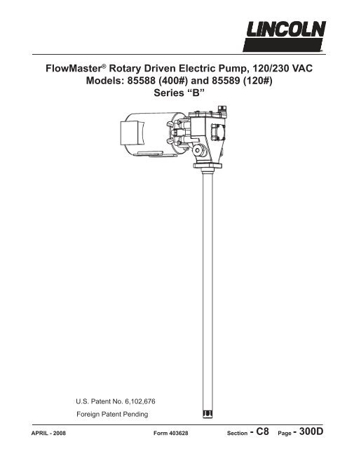
FlowMaster ® <strong>Rotary</strong> <strong>Driven</strong> <strong>Electric</strong> <strong>Pump</strong>, 120/230 VAC<br />
Models: 85588 (400#) and 85589 (120#)<br />
Series “B”<br />
APRIL - 2008<br />
U.S. Patent No. 6,102,676<br />
Foreign Patent Pending<br />
Form 403628<br />
Section<br />
- C8<br />
Page - 300D
FlowMaster <strong>Rotary</strong> <strong>Driven</strong> <strong>Electric</strong> <strong>Pump</strong><br />
Page Number - 2<br />
Table of Contents<br />
Page<br />
Safety..…….……………................................................................2<br />
Description....................................................................................2<br />
Appropriate Use................................................................3<br />
<br />
Installing the <strong>Pump</strong>.....................................................................3<br />
Operation.....................................................................................4<br />
Crank Case Oil................................................................................4<br />
<strong>Pump</strong> Dimensions.............................................................5<br />
Trouble Shooting............................................................................6<br />
Required Tools...............................................................................7<br />
Maintenance and Repair...........................................................8<br />
Repair Parts List............................................................................23<br />
Safety<br />
Read and carefully observe these operating instructions before<br />
unpacking and operating the pump! The pump must be operated,<br />
maintained and repaired exclusively by persons familiar<br />
with the operating instructions. Local safety regulations regarding<br />
installation, operation and maintenance must be followed.<br />
Operate this pump only after safety instructions and this service<br />
manual are fully understood.<br />
Indicates a potentially hazardous situation which, if not avoided,<br />
could result in death or serious injury.<br />
Indicates a potentially hazardous situation which, if not avoided,<br />
may result in minor or moderate injury.<br />
Safety Instructions<br />
This equipment generates very high grease pressure.<br />
Extreme caution should be used when operating this equipment<br />
as material leaks from loose or ruptured<br />
<br />
body causing serious bodily injury. Adequate protection is<br />
recommended to prevent splashing of material onto the skin<br />
or into the eyes.<br />
<br />
medical care immediately. Do not treat as a simple cut. Tell<br />
<br />
Inspection<br />
If overpressurizing of the equipment is believed to have occurred,<br />
contact the factory authorized warranty and service<br />
center nearest you for inspection of the pump.<br />
Specialized equipment and knowledge is required for repair of<br />
this pump. Contact the factory authorized warranty and service<br />
center nearest you for repair or adjus®ents other than mainte-<br />
<br />
Annual inspection by the factory authorized warranty and service<br />
center nearest you is recommended.<br />
A list of factory authorized warranty and service centers is available<br />
upon request at www.lincolnindustrial.com<br />
Damaged <strong>Pump</strong>s<br />
Any pump that appears to be damaged in any way, is badly<br />
worn or operates abnormally, shall be removed from use until<br />
repairs are made. Contact the factory authorized warranty and<br />
service center nearest to you for repairs.<br />
Description<br />
A newer version of the FlowMaster pump was introduced in July of<br />
2008. These units incorporate the following improvements:<br />
* Bushing & plunger seals used along with elastomer cup seals for<br />
longer life and better high temperature operation.<br />
* A crankcase oil dipstick<br />
* Hardened and ground section on the reciprocating tube for longer<br />
life and better crankcase oil control.<br />
<br />
pivot pin anchor.<br />
* Improved pivot pin fastener with deeper Allen hex socket.<br />
All of the improved parts can be used with the older model pumps,<br />
so the upgraded parts and subassemblies will now be supplied<br />
to repair older model pumps. Please see the “Maintenance and<br />
Repair” section for a list of the new repair kits and their proper application.<br />
85588 - 400 pound pump, 360RPM maximum, 5,000 psi<br />
max. pressure rating<br />
85589 - 120 poung pump, 360 RPM maximum, 5,000 psi<br />
maxpressure rating<br />
General Description<br />
The <strong>Lincoln</strong> <strong>Industrial</strong> rotary A/C electric pump uses a 120-230<br />
VAC dual voltage motor and a single stage planetary gear<br />
drive. Grease output is proportional to the pump RPM.<br />
The pump is primarily designed for centralized lubrication systems<br />
such as the Single Line parallel, Single Line Progressive<br />
and Two Line systems.<br />
The pump is driven by the rotary motion of the electric motor.<br />
<strong>Rotary</strong> motion is converted to reciprocating motion through an<br />
eccentric crank mechanism. The reciprocating action causes<br />
the pump cylinder to move up and down. The unit is a positive<br />
displacement double acting pump as grease output occurs during<br />
both the up and down stroke.<br />
During the down stroke, the pump cylinder is extended into the<br />
grease. Through the combination of shovel action and vacuum<br />
generated in the pump cylinder chamber, the grease is forced<br />
into the pump cylinder. Simultaneously, grease is discharged<br />
through the outlet of the pump. The volume of grease during<br />
intake is twice the amount of grease output during one cycle.<br />
During the upstroke, the inlet check closes, and one half of the<br />
grease taken in during the previous stroke is transferred through<br />
Form 403628
the outlet check and discharged to the outlet port. Typical output<br />
of the pump is shown on page 3.<br />
Appropriate Use<br />
All pump models are exclusively designed to pump and<br />
dispense lubricants using 120 VAC or 230 VAC electric<br />
power, depending on how the motor is wired.<br />
<br />
exceeded.<br />
Any other use not in accordance with instructions will<br />
result in loss of claims for warranty and liability.<br />
<br />
Operating Temperature, ºF (ºC)- -40 to +150 (-40 to 65)<br />
Operating Voltage, VAC - 120, 230<br />
Frequency 60 Hz<br />
<strong>Pump</strong> Outlets, In - 1/4 NPTF<br />
Weight, Lbs (Kg) - 45 (20)<br />
Max. Outlet Pressure - 5,000 PSI<br />
Form 403628<br />
©<br />
Do not exceed maximum rated outlet pressure for these<br />
pumps. Exceeding rated pressure may result in damage to<br />
system components and personal injury.<br />
AC ELECTRIC PUMP<br />
PERFORMANCE SPECIFICATIONS<br />
CUBIC IN/MIN Test conducted with NLGI #1©<br />
Grade Grease at 1000 psi Backpressure<br />
TEMPERATURE °F (°C) 350 RPM<br />
80 (27) 25.4©<br />
40 (4) 24.2©<br />
20 (-7) 23©<br />
FlowMaster <strong>Rotary</strong> <strong>Driven</strong> <strong>Electric</strong> <strong>Pump</strong><br />
Illustration 1<br />
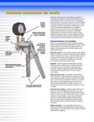
Installing the <strong>Pump</strong><br />
Typical installation is shown only as a guide for selecting and<br />
installing system components. Contact your <strong>Lincoln</strong><br />
<strong>Industrial</strong> representative for assistance in designing a<br />
<br />
The pump was tested in light weight oil which was left in to<br />
protect the pump from corrosion. Flush the pump before connecting<br />
it to the system to prevent contamination of the grease<br />
with residual oil.<br />
1. Mount the pump securely on the drum cover so that it<br />
cannot move or vibrate during operation.<br />
2. Connect material supply line to the pump outlet. Install<br />
Safety Unloader Valve (such as 272722) (Item A, Illuatraion<br />
4, Page 4) to the outlet on the opposite side of the pump to<br />
ensure the maximum pressure is always below 5,000© psi.<br />
3. Install high pressure shut-off valve in the material supply<br />
line. (Required) (Item C, Illustration 4, Page 4)<br />
4. Connect 120 VAC or 230 VAC power supply to the<br />
solenoid valve (35). (See Illustration #1.)<br />
5. Wire the motor for the proper line voltage (see<br />
Illustration 2). Be sure to fuse the motor as recommended<br />
in Illustration 3.<br />
6. Mount the motor to the drum cover using the auxillary<br />
mount.<br />
Mount the pump securely on the drum cover. Failure to do so<br />
could result in personal injury and equipment damage.<br />
Always install a relief valve in the pump outlet to insure pump<br />
pressure is below 5,000 PSI. Use high pressure components<br />
<br />
splashing in the eyes or on the skin.<br />
© Indicates change<br />
Page Number - 3
FlowMaster <strong>Rotary</strong> <strong>Driven</strong> <strong>Electric</strong> <strong>Pump</strong><br />
ELECTRIC FLOWMASTER PUMP<br />
120 (230) VAC, 5:1 gear ratio, 85588 & 85589<br />
BACK PRESSURE (PSI) RPM CURRENT DRAW (AMPS @ 120 (230) VAC)*<br />
0 360 1 (.5)<br />
1000 350 2.6 (1.3)<br />
2000 350 3.7 (1.8)<br />
3000 350 5.1 (2.5)<br />
4000 350 6.5 (3.3)<br />
5000 350 7.8 (3.9)<br />
<br />
VAC) is recommended.<br />
Illustration 3<br />
Page Number - 4<br />
Illustration 2<br />
Illustration 4<br />
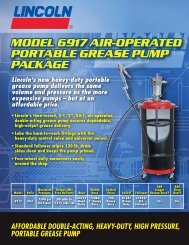
A - Safety Unlader 272722<br />
B -120 VAC or 230 VAC<br />
C- Outlet Shut-off Valve<br />
D - Material Supply Line<br />
E - Follower Plate (85492 for 120 lb. drum only)<br />
F - Drum Cover (85475 for 400 lbs., 85474 for 120 lbs.)<br />
G - Auxillary Motor Mount<br />
H - Field Installed Fuse<br />
AC motor requires an auxillary mount. Do not operate the<br />
pump without properly mounting the motor to the drum cover.<br />
Operation<br />
1. Remove the pump outlet line.<br />
2. With the pump in a full container of lubricant, energize the<br />
pump. Make sure all air has been expelled from the pump<br />
<br />
3. Reattach the pump outlet line.<br />
Never allow the pump to run dry of lubricant. Monitor the<br />
<br />
Maintenance and Repair<br />
<br />
or moving parts, relieve hydraulic and outlet pressure before<br />
servicing or repairing the pump.<br />
Always use <strong>Lincoln</strong> <strong>Industrial</strong> parts for service and repair.<br />
Crankcase Oil Service Interval Recommendations<br />
Check the oil level after every 750 hours of machine operation,<br />
or every month.<br />
Change the oil after every 2,000 hours of machine operation<br />
or every year.<br />
Use SAE 10W30 motor oil in all units used in an ambient<br />
temperature between 150 to -40°F. For ambient temperatures<br />
between 50 to -70°F, use Mobil Arrow HFA Low<br />
Temperature oil.<br />
Oil level should be at the dot on the dipstick (middle of the<br />
crankshaft) using 10W30 motor oil (15 oz.).<br />
Form 403628
© Indicates change<br />
Form 403628<br />
FlowMaster <strong>Rotary</strong> <strong>Driven</strong> <strong>Electric</strong> <strong>Pump</strong><br />
Illustration #5<br />
MODEL DIM "A" in (mm) DIM "B" in (mm)<br />
85588 34.0 (864) 42.1 (1069)©<br />
85589 27.5 (699) 36.1 (917.7)©<br />
Page Number - 5
FlowMaster <strong>Rotary</strong> <strong>Driven</strong> <strong>Electric</strong> <strong>Pump</strong><br />
Page Number - 6<br />
Troubleshooting<br />
Condition Possible Cause Corrective Action<br />
<strong>Pump</strong> does not run. <strong>Pump</strong> is seized or damaged. Dismantle the pump and repair<br />
defective or seized component. See<br />
disassembly and assembly<br />
procedure.<br />
<strong>Pump</strong> speeds up or runs erratically. Low level of grease or reservoir<br />
is empty<br />
<br />
Follower plate is stuck and separated Check follower plate and container<br />
from grease. for damage.<br />
<strong>Pump</strong> piston or checks are worn. Disassemble the pump and repair.<br />
<strong>Pump</strong> runs, but output is low. <strong>Pump</strong> speed set too low. Increase motor speed setting.<br />
Faulty inlet (25, 27), faulty discharge<br />
check (18, 19) or damaged o-rings (26).<br />
Replace faulty components.<br />
Weepage from housing cover 30. Cup seal (15) or O-Ring (13b) wore out. Check the seals and replace if<br />
necessary.<br />
<strong>Pump</strong> becomes noisy. No crank case oil. Add crank case oil. Remove crankcase<br />
cover (30a) from <strong>Pump</strong> Housing (67).<br />
Oil level should be at the middle of<br />
the crankshaft (37). Check dipstick<br />
to verify.<br />
If unit is used in cold climates, use<br />
Mobil Arrow HFA Hydraulic Oil in<br />
crankcase.<br />
Worn wrist pin bushing (12). Check the bushings and replace if<br />
necessary.<br />
<strong>Pump</strong> dies not build pressure. Foreign material holding lower Dismantle & clear check. Consider<br />
check open. installing inlet strainer (272180)<br />
before returning pump to service.<br />
Motor runs, but no pump outlet. Gearset or adapter shaft stripped or Dismantle and replace damaged<br />
broken. part.<br />
Form 403628
Tools Required for Maintenance, Repair and<br />
Adjustment<br />
7/16” open end wrench<br />
1-1/2” open end wrench<br />
3/4 open end wrench<br />
12” cresent wrench<br />
1/8 Allen wrench<br />
5/32 Allen wrench<br />
1/4 Allen wrench<br />
5/16 Allen wrench<br />
3/8 Allen wrench<br />
1/4 drive socket<br />
1/4 socket<br />
5/16 socket<br />
Flat blade screwdriver .10” wide and .025” thick<br />
Pick to remove seals and spiral retaining rings<br />
Small snap ring pliers<br />
Special tool kit 276275<br />
Phillips Screwdriver<br />
1/2 Allen Wrench<br />
Hammer<br />
Torque Wrench (Ft/lbs and In/lbs)<br />
Hex Allen Socket Adapters (Req;d to torque Allen Screws)<br />
Loctite 242 Medium Strength Thread Lock or Equivalent<br />
<br />
Loctite 222MS Threadlock or Equivalent<br />
Form 403628<br />
FlowMaster <strong>Rotary</strong> <strong>Driven</strong> <strong>Electric</strong> <strong>Pump</strong><br />
Page Number - 7
FlowMaster <strong>Rotary</strong> <strong>Driven</strong> <strong>Electric</strong> <strong>Pump</strong><br />
Maintenance and Repair<br />
1. Using a shortened 5/16 allen wrench, remove the four<br />
gearbox assembly mounting screws (item 46). (Reassembly:<br />
Torque to 20-25 Ft. Lbs. (27.1 - 33.9 Nm).)<br />
1a. Remove AC mtoro (Item 50) and gearbox assembly<br />
(Items 43-48).<br />
2. Remove motor mounting screws (Item 51). (Reassembly:<br />
torque to 100-110 in. lbs. (11.3 - 12.4 Nm).)<br />
3. Remove gearbox assembly (Items 43-48).<br />
Page Number - 8<br />
4. Remove O-ring seal from gearbox (Item 44). (Reassembly<br />
recommendations: replace O-ring.)<br />
5. Remove shaft coupler (Item 49).<br />
6. Remove adaptor shaft (item 41).<br />
7. Remove gearbox O-ring seal (Item 44). (Reassembly<br />
recommendation: replace O-ring)<br />
Form 403628
8. Remove dipstick (Item 30b).<br />
9. Drain oil (reassembly recommendations: use SAE 10W30<br />
<br />
10. Remove housing cover screws (Item 28). (reassembly recommendations:<br />
replace screw gaskets(item 29))<br />
11. Remove housing cover (item 30) and Gasket (Item 31).<br />
(Reassembly recommendation: replace gasket)<br />
Form 403628<br />
FlowMaster <strong>Rotary</strong> <strong>Driven</strong> <strong>Electric</strong> <strong>Pump</strong><br />
Maintenance and Repair<br />
12. Remove bearing cover screws (Item 66) with lockwashers<br />
(Item 65). (Reassembly torque: 32-38 in. lbs. (3.6 - 4.3 Nm).)<br />
13. Remove bearing cover (Item 64).<br />
14. Remove bearing cover O-ring (Item 63). (Reassembly<br />
recommendations: replace bearing cover O-ring.)<br />
15. Note C-clip location on shaft (Item 62).<br />
Page Number - 9
FlowMaster <strong>Rotary</strong> <strong>Driven</strong> <strong>Electric</strong> <strong>Pump</strong><br />
Maintenance and Repair<br />
Page Number - 10<br />
16. Remove clip.<br />
17. Using 2 1/2” dia. steel pipe included in the special tool kit<br />
(276275), support the front housing seal and bearing as shown.<br />
18. Support crankrod as shown with a stack of washers or other<br />
spacer of the proper thickness.<br />
19. Drive out the pump shaft<br />
(Item 37) using nylon rod<br />
included in special tool kit<br />
(276275).<br />
20. <strong>Pump</strong> shaft will drop inside the support pipe when it clears<br />
the pump assembly.<br />
21. Loosen outlet pin nuts (Item 32). (Reassembly torque:<br />
30-35 Ft. Lbs. (40.7 - 47.5 Nm).)<br />
22. Remove outlet nuts (item 32) from both sides of pump.<br />
(Reassembly recommendation: use Loctite 242 or equivalent<br />
on outlet nut threads.<br />
Form 403628
23. Remove spiral retaining ring (item 59) from housing tube.<br />
Form 403628<br />
FlowMaster <strong>Rotary</strong> <strong>Driven</strong> <strong>Electric</strong> <strong>Pump</strong><br />
Maintenance and Repair<br />
24. Remove shovel plug (Item 58) and spacer (Item 56b) from<br />
housing tube.<br />
Page Number - 11
FlowMaster <strong>Rotary</strong> <strong>Driven</strong> <strong>Electric</strong> <strong>Pump</strong><br />
Maintenance and Repair<br />
25. Push pump element (items 1 through 27) out of housing<br />
tube with nylon rod included in tool kit (276275) and hammer.<br />
(Reassembly recommendation: replace pump element in housing<br />
tube with housing tube slightly loose, then torque housing<br />
tube (Item 56a) to pump housing (Item 73) to 20-25 Ft. Lbs.<br />
26. Pull pump element free of housing.<br />
Page Number - 12<br />
27. Remove housing tube (Item 56a). (Reassembly Torque: 20<br />
to 25 Ft. Lbs.(27.1 - 33.9 Nm).)<br />
28. Exploded view of housing tube (Item 56a), spacer<br />
(Item 56) and Shovel Plug (Item 58).<br />
29. Remove bronze bushing (Item 52).<br />
30. Remove oil seal O-ring (Item 53) and backup washer (Item<br />
59). (Reassembly recommendation: replace O-ring seal and<br />
<br />
then the O-ring.)<br />
Form 403628
31. Remove wrist pin bushing screws (Item 11). (Reassembly<br />
torque: 100-110 in. lbs. (11.3 - 12.4 Nm).) Reassembly recommendations:<br />
use Loctite 242 or equivalent on screw threads).<br />
32. View of wrist pin bushing (Item 12).<br />
33. Press out wrist pin bushing (Item 12) with 5/16-24 bolt<br />
(from 276275 kit), needed since pivot bushings often stick in<br />
wrist pin anchor (Item 13a).<br />
34. Remove wrist pin bushing (Item 12).<br />
Form 403628<br />
FlowMaster <strong>Rotary</strong> <strong>Driven</strong> <strong>Electric</strong> <strong>Pump</strong><br />
Maintenance and Repair<br />
35. Remove crankkrod and eccentric assembly (Items 1-7).<br />
36. Loosen wrist pin anchor (Item 13a). (Reassembly torque:<br />
20 - 25 Ft. Lbs. (27.1 - 33.9 Nm).)<br />
37. Remove wrist pin anchor (Item 13a). (Reassemblly recommendations:<br />
replace O-ring seal (Item 13b), be sure threads on<br />
wrist pin anchor (Item 13a) are clean and free of all oil or other<br />
<br />
38. View of plunger tube and plunger tube bushing assembly<br />
(Items 10, 10a, 10b, 10c and 10d).<br />
Page Number - 13
FlowMaster <strong>Rotary</strong> <strong>Driven</strong> <strong>Electric</strong> <strong>Pump</strong><br />
Maintenance and Repair<br />
Page Number - 14<br />
39. Loosen plunger tube (Item<br />
10). (Reassembly torque:<br />
100-110 in. lbs. (11.3 - 12.4<br />
Nm).)<br />
40. Remove plunger tube (Item 10) and associated parts.<br />
(Reassembly recommendations: replace O-ring (Item 10c) on<br />
bushing (Item 10a). Use Loctite 242 or equivalent on plunger<br />
tube threads.)<br />
41. View of bushing assembly (Items 10 through 10d) removed.<br />
42. View of wrist pin anchor (Item 13a) showing upper cup seal<br />
(Item 15) and nylon back up washer (Item 14).<br />
43. Pull cup seal (Item 15) out of wrist pin anchor (Item 13a).<br />
44. Remove cup seal (Item 15) and backup washer (Item 14).<br />
(Reassembly recommendations: replace cup and seal and<br />
backup washer. See detail below for orientation)<br />
Series “B”<br />
45. Hold outlet pin (Item 8) and plunger tube (Item 10) in vise.<br />
Form 403628
46. Loosen plunger tube (Item 10) from outlet pin (Item 8). (reassembly<br />
torque: 100-110 in.-lbs. (11.3 - 12.4 Nm).)<br />
47. Remove plunger tube (Item 10). (Ressembly recommendations;<br />
replace o-ring (item 9). use Loctite 242 or equivalent on<br />
plunger tube threads.)<br />
48. Remove O-ring (Item 9).<br />
Form 403628<br />
FlowMaster <strong>Rotary</strong> <strong>Driven</strong> <strong>Electric</strong> <strong>Pump</strong><br />
Maintenance and Repair<br />
49. View of O-ring (Item 9)<br />
removed.<br />
50. Remove C-clip (Item 10d).<br />
51. Remove O-ring (Item 10c).<br />
52. Remove backup washer (Item 10b).<br />
53. View of upper bushing and seals (Items 10-10d).<br />
Page Number - 15
FlowMaster <strong>Rotary</strong> <strong>Driven</strong> <strong>Electric</strong> <strong>Pump</strong><br />
Maintenance and Repair<br />
54. Loosen check seal housing (Item 27) with 3/8 Allen<br />
wrench. (Reassembly torque: 20-25 ft. lbs.(27.1 - 33.9 Nm).)<br />
55. Check seat housing assembly (Item 27) and associated<br />
parts removed. (Reassembly recommendations: replace O-ring<br />
seal (Item 26). Apply Loctite 242 or equivalent to check seat<br />
housing threads.)<br />
Page Number - 16<br />
56. Remove ball cage (Item 24), check ball (Item 25) and Oring<br />
seal (Item 26) from check seat housing (Item 27).<br />
Form 403628
57. Remove plunger and bushing assembly (Item 19) from<br />
reciprocating tube (Item 20). (Reassembly recommendations:<br />
replace O-ring seal (Item 26.)<br />
Remove lower cup (Item 21) from reciprocating tube (Item 20).<br />
(Reassembly recommendations; replace lower cup seal. See<br />
detail for orientation.) Remove pump bushing (19a) from pump<br />
plunger (19).<br />
Top of <strong>Pump</strong> Bottom of <strong>Pump</strong><br />
58. To remove lower plunger, using special tool provided in kit<br />
276275.<br />
59. With the tool in place, insert the pin from tool kit (276275)<br />
through the tool and into the plunger outlet hole.<br />
Form 403628<br />
FlowMaster <strong>Rotary</strong> <strong>Driven</strong> <strong>Electric</strong> <strong>Pump</strong><br />
60. Remove plunger (Item 19). (Reassembly torque: 100-110<br />
in. lbs. (11.3 - 12.4 Nm).) (Reassembly recommendations: use<br />
Loctite 242 or equivalent on plunger threads).<br />
61. Push out check ball (Item 18) and check spring (Item 17).<br />
62. Clamp crank rod/eccentric assembly (Items 1-7) in vise.<br />
Page Number - 17
FlowMaster <strong>Rotary</strong> <strong>Driven</strong> <strong>Electric</strong> <strong>Pump</strong><br />
Maintenance and Repair<br />
<br />
100-110 in. lbs.)<br />
mendation:<br />
use loctite 242 on screw threads).<br />
ance<br />
weights (Item 2).<br />
Page Number - 18<br />
66. Remove inner and outer retaining ring (Item 5 and Item 3)<br />
from both sides.<br />
67. Place assembly on 2” schedule 40 pipe.<br />
68. Drive crank eccentric (Item 6) out of ball bearing (Item 7).<br />
Form 403628
69. Drive ball bearing (Item 7) out of crank rod (Item 4).<br />
70. Remove O-Ring seal (Item 33) from outlet nut (Item 32).<br />
71. Remove O-ring seal (Item 34) and backup washer (Item<br />
35) from outlet nut (Item 32). Note the position of the backupwasher<br />
in photo.<br />
Form 403628<br />
FlowMaster <strong>Rotary</strong> <strong>Driven</strong> <strong>Electric</strong> <strong>Pump</strong><br />
Maintenance and Repair<br />
72. Reassembly recommendations: To install the O-ring (Item<br />
34) and backupwasher (Item35) most easily, install the backup<br />
<br />
73. And then feed the O-ring<br />
(Item 34) under the backup<br />
<br />
bulge of the O-ring with a blunt<br />
rod.<br />
Page Number - 19
FlowMaster <strong>Rotary</strong> <strong>Driven</strong> <strong>Electric</strong> <strong>Pump</strong><br />
Maintenance and Repair<br />
Page Number - 20<br />
50<br />
49<br />
48<br />
47<br />
46<br />
45<br />
44<br />
43<br />
51a<br />
51<br />
Form 403628
41<br />
Form 403628<br />
40<br />
37<br />
38<br />
39<br />
37a<br />
43-51 Previous Page<br />
FlowMaster <strong>Rotary</strong> <strong>Driven</strong> <strong>Electric</strong> <strong>Pump</strong><br />
Maintenance and Repair<br />
30b<br />
30c<br />
55<br />
54<br />
56a<br />
31<br />
53<br />
30a<br />
67<br />
52<br />
57<br />
Part of 56a<br />
56b<br />
58<br />
59<br />
36<br />
28<br />
35<br />
29<br />
60<br />
34 33<br />
62<br />
61<br />
63<br />
32<br />
64<br />
65<br />
66<br />
Page Number - 21
FlowMaster <strong>Rotary</strong> <strong>Driven</strong> <strong>Electric</strong> <strong>Pump</strong><br />
Maintenance and Repair<br />
Page Number - 22<br />
1<br />
2<br />
3<br />
21<br />
19<br />
19a<br />
5<br />
26<br />
7<br />
9<br />
10<br />
10a<br />
10b<br />
10c<br />
10d<br />
4<br />
6<br />
5<br />
8<br />
3<br />
2<br />
24<br />
25<br />
17<br />
18<br />
13b<br />
20<br />
27<br />
16<br />
13a<br />
14<br />
15<br />
11<br />
12<br />
1<br />
Form 403628
© Indicates change<br />
* Included in 275383 Soft Parts Kit.<br />
Note 1: Part is included win item 56a.<br />
Form 403628<br />
FlowMaster <strong>Rotary</strong> <strong>Driven</strong> <strong>Electric</strong> <strong>Pump</strong><br />
Maintenance and Repair<br />
Repair Parts List<br />
(Common to all Models)<br />
Item No. Qty Description All Models Item No. Qty Description All Models<br />
1 2 Flat Head Screw 275006 © 32 2 Outlet, Pin-Nut 270619<br />
2 2 Counter Weight 272197 33 2 O-Ring *<br />
3 2 Retaining Ring 270609 34 2 O-Ring *<br />
4 1 Crankrod 270665 35 2 Backup Washer *<br />
5 2 Retaining Ring 270608 36 1 O-Ring 272567<br />
6 1 Crank Eccentric 270666 37 1 <strong>Pump</strong> Shaft 272548<br />
7 1 Ball Bearing 270607 37a © 1 Woodruff Key 272560<br />
8 1 Outlet Pin 270670 38 © 1 Retaining Ring 272561<br />
9 1 O-Ring (Nitrile) * 39 © 1 Ball Bearing 272556<br />
10 1 Plunger Tube See Note 2 40 1 Shaft Seal 272554<br />
10a 1 Plunger Bushing See Note 2 41 1 Adapter Shaft 272546<br />
10b 1 Steel Back-up Washer See Note 2 43 2 Gearbox Housing 272541<br />
10c 1 O-ring See Note 2* 44 1 O-Ring 272544<br />
10d 1 Retainer Clip See Note 2 45 4 Lock Washer 272566<br />
11 2 Pivot Screw 275006 © 46 4 Screw 272564<br />
12 2 Wrist Pin Bushing 275005 © 47 1 Gear Set 272573<br />
13a 1 Wrist Pin Anchor 274992 © 48 4 Screw 272574<br />
13b 1 O-ring * © 49 © 1 Motor Coupler 272709**<br />
14 1 Backup Washer * 50 1 Motor 272768<br />
15 1 Cup Seal 51 4 Screw 272568<br />
(Polyurethane) * 51a © 3 Lock Washer 272569<br />
16 1 Plunger Link Rod See Chart Below 52 1 Bronze Bearing 270674<br />
17 1 Spring *© 53 1 O-Ring (Polyrethane) *<br />
18 1 Ball *© 54 1 Backup Washer *<br />
19 1 <strong>Pump</strong> Plunger & Bushing 275002 © 55 1 O-Ring (Nitrile) *<br />
19a© 1 <strong>Pump</strong> Bushing See Note 3 56a 1 Housing Tube See Chart Below<br />
20 1 Reciprocating Tube See Chart Below 56b © 1 Spacer 276279<br />
21 1 Cup Seal 57 1 Bronze Bushing Note 1<br />
(Polyurethane) * 58 1 Shovel Plug 270707<br />
24 1 Ball Cage 272179 © 59 1 Retaining Ring 270705<br />
25 1 Ball *© 60 © 1 Retaining Ring 272562<br />
26 1 O-Ring (Nitrile) * 61 © 1 Ball Bearing 272555<br />
27 1 Check Seat 270664 62 1 Retaining Ring 272563<br />
28 6 Self-Threading 63 1 O-Ring 272559<br />
Screw (#8 x 1/2) 270633 64 1 Bearing Cover 272549<br />
29 6 Gaskets (Screw) 252986 65 4 Lock Washer 66051<br />
30a 1 Housing Cover 275009 © 66 4 Screws 272557<br />
30b 1 Dipstick 275008 © 67 © 1 <strong>Pump</strong> Housing 272540<br />
30c 1 O-ring * © * Repair Kit 275383<br />
31 1 Cover Gasket (Nitrile) *<br />
Repair Parts List<br />
(Non-common items)<br />
Item Qty. Description Model Model<br />
No. 85589 (120lb) 85588 (400lb)<br />
16 1 Plunger Link Rod 270648 270645<br />
20 1 Reciprocating Tube 275018 275158<br />
56 1 Housing Tube 275191 275192<br />
1 Safety Unloader 272722 ---<br />
Note 2: Parts included in kits 275186 & 275382.<br />
Note 3: Part is included in item 19.<br />
Page Number - 23
FlowMaster <strong>Rotary</strong> <strong>Driven</strong> <strong>Electric</strong> <strong>Pump</strong><br />
Maintenance and Repair<br />
Converting Series A to Series B <strong>Pump</strong>s<br />
Series A Service page needed for teardown<br />
Series B Service page needed for re-assembly<br />
Page Number - 24<br />
Repair Kit Selection Chart<br />
Item # Kit #<br />
1 to 8, 24, 25, 27, 32, 36 to 52, 58 to 67 No kit – parts identical for Series A and Series B.<br />
9, 10, 10a, 10b, 10c, 10d, 14, 15 275186 - Upper Bushing & Plunger Kit<br />
17, 18, 19, 19a, 21, and 26 275187 - Lower Bushing & Plunger Kit<br />
See chart for reciprocating tube P/N on page 23 for<br />
20<br />
Series B<br />
28, 29, 30, 30a, 30b, and 31 275381 - Housing Cover Kit<br />
Housing tube kits (chart) See chart Pg. 23 Series B<br />
56a, 56b and 57 (pressed into 56a)<br />
(Plus 276279 spacer)<br />
Repair Kit 275383 Repair Kit<br />
Form 403628
Repair Series B Only<br />
Americas:<br />
One <strong>Lincoln</strong> Way<br />
St. Louis, MO 63120-1578<br />
USA<br />
Phone +1.314.679.4200<br />
Fax +1.800.424.5359<br />
Form 403628<br />
FlowMaster <strong>Rotary</strong> <strong>Driven</strong> <strong>Electric</strong> <strong>Pump</strong><br />
Europe /Africa/Middle East<br />
<strong>Lincoln</strong> GmbH<br />
Heinrich-Hertz-Str. 2-8<br />
69190 Walldorf - Germany<br />
Phone/Fax +49.6227.33-0/-259<br />
www.lincolnindustrial.de<br />
Repair Kit Selection Chart<br />
Item # Kit #<br />
1 to 8, 24 to 30a, 36 to 52, 56a to 67 Not in kits, order individually if needed<br />
9, 10, 10a, 10b, 10c, 10d, 14, 15, 275186 - Upper Bushing & Plunger Kit<br />
11, 12, 13a, (do not use spacer # 275376) 275188 - Pivot Pin & Anchor Kit<br />
17, 18, 19, 19a, 21, 26, 275187 - Lower Bushing & Plunger Kit<br />
9, 13b, 14, 15, 17, 18, 21, 25, 26, 30b, 31, 33, 34,<br />
35, 53, 54, 55, 275383 - Repair Kit<br />
<br />
51 Changi Business Park<br />
Central 2<br />
#09-06 The Signature<br />
Singapore 486066<br />
Phone +65.6588.0188<br />
Fax +65.6588.3438<br />
© Copyright <strong>Lincoln</strong> <strong>Industrial</strong> Corp.<br />
2008<br />
Printed in USA<br />
Web site:<br />
www.lincolnindustrial.com<br />
Page Number - 25