Aerospace Research - ISTC Funded Projects 1994-2009
Aerospace Research - ISTC Funded Projects 1994-2009
Aerospace Research - ISTC Funded Projects 1994-2009

You also want an ePaper? Increase the reach of your titles
YUMPU automatically turns print PDFs into web optimized ePapers that Google loves.
INTERNATIONAL SCIENCE AND TECHNOLOGY CENTER<br />
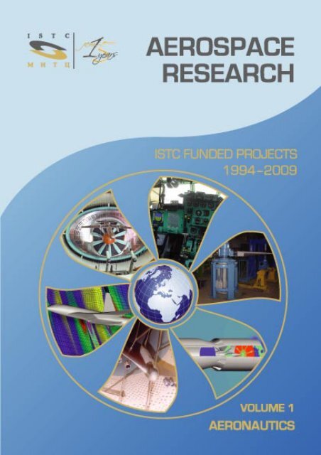
AEROSPACE<br />
RESEARCH<br />
<strong>ISTC</strong> FUNDED PROJECTS<br />
<strong>1994</strong>–<strong>2009</strong><br />
AERONAUTICS<br />
VOLUME 1<br />
Edited by<br />
Waclaw Gudowski (<strong>ISTC</strong>)<br />
Tatiana Ryzhova (<strong>ISTC</strong>)<br />
Sergey Frolov (ICP RAS)<br />
TORUS PRESS<br />
Moscow – <strong>2009</strong>
<strong>Aerospace</strong> <strong>Research</strong>: <strong>ISTC</strong> <strong>Funded</strong> <strong>Projects</strong> <strong>1994</strong>–<strong>2009</strong>. Volume 1. Aeronautics / Edited by<br />
W. Gudowski, T. Ryzhova, S. Frolov. – 172 p.: 86 ill.<br />
The book contains the synopses of 35 projects in Aeronautics funded by <strong>ISTC</strong> Funding Parties – the<br />
European Union, Japan, the United States of America, and Canada – during 15 years (<strong>1994</strong>–<strong>2009</strong>).<br />
Project description gives a brief overview of its background, objectives, scope of work, and<br />
results – expected for ongoing projects and obtained for completed projects. Some administrative<br />
information including tech code/area/field, status and technology development phase according<br />
to <strong>ISTC</strong> taxonomy are also given, as well as information about funding parties, allocated funding,<br />
project duration, and commencement date.<br />
The names of foreign organizations expressed interest in the project and participated in the<br />
project as Foreign Collaborators are presented in the synopses and provide an overview of the<br />
international cooperation in Aeronautics strengthened through <strong>ISTC</strong> projects.<br />
The book also provides information on core and supplemental <strong>ISTC</strong> programs, including Partner<br />
program, and main <strong>ISTC</strong> partners in Aeronautics.<br />
In addition, brief information on institutes – <strong>ISTC</strong> recipients in Aeronautics and a list of project<br />
proposals, which obtained good recommendation by <strong>ISTC</strong> scientific experts, but have not received<br />
funding yet, provide readers with an opportunity to meet their R&D needs through development<br />
cooperation/partnership with Russia/CIS.<br />
© <strong>ISTC</strong>, <strong>2009</strong>
The International Science and Technology<br />
Center is an international organization, created<br />
to serve the goal of international scientific<br />
cooperation. The European Union, Japan, the<br />
Russian Federation, and the United States of<br />
America started work on the basis of a<br />
multinational agreement established in 1992.<br />
Canada, Norway, and the Republic of Korea<br />
later became signatories to the <strong>ISTC</strong><br />
Agreement, with Canada becoming a full<br />
Governing Board Member in 2004.<br />
Consequently, <strong>ISTC</strong> started its work in <strong>1994</strong><br />
based on the Decree of the President of<br />
Russian Federation and since then <strong>ISTC</strong> has<br />
funded and managed more than 2,650 projects<br />
with a total value of 816 million USD. Over $30<br />
million USD has been used to fund aerospace<br />
and aircraft research, with many other projects<br />
completed or developed in related fields.<br />
<strong>ISTC</strong> has today 39 member states and offers a<br />
wide spectrum of programs, services and<br />
activities. The <strong>ISTC</strong> Secretariat, based in<br />
Moscow, has about 150 staff members, among<br />
whom there are researchers, commercialization<br />
specialists, financial experts, and<br />
administrative staff.<br />
Currently, the <strong>ISTC</strong> funds cooperative research<br />
projects in a wide range of scientific disciplines<br />
and technology areas. Future strategic<br />
priorities of <strong>ISTC</strong> are those that make the world<br />
safer and more secure – environment,<br />
renewable and environmental friendly energy,<br />
nuclear safety, and human health are at the<br />
first place. Obviously, many of these areas<br />
directly relate to the development of the<br />
aviation and aerospace industry and <strong>ISTC</strong> is<br />
proud of its record in developing projects and<br />
international relationships in this sphere.<br />
<strong>ISTC</strong> has established strategic partnership<br />
with many Russian and other countries of the<br />
CIS innovation foundations and organizations,<br />
governmental organizations and agencies,<br />
busi ness schools, legal companies, foundations,<br />
and investors that work to further<br />
strengthen the diversity of the national<br />
economies.<br />
Aeronautics<br />
<strong>ISTC</strong> is also an organization that assists private<br />
industry in technology search, connecting<br />
international industry with high quality<br />
institutes in Russia and beyond. <strong>ISTC</strong> has over<br />
400 commercial and governmental agency<br />
partners from around the globe, many of<br />
whom are engaged in R&D projects with<br />
experts from Russia and other countries of the<br />
CIS, and are developing technologies and<br />
applications that all of us will benefit from.<br />
This book profiles many of the success stories<br />
resulting from the efforts of the Center and its<br />
many Partners, from breakthrough research in<br />
physics and aerodynamics, through to the<br />
investigation and development of greener and<br />
safer air transport. As an organization born of<br />
necessity and foresight back in the early<br />
nineties, I believe that <strong>ISTC</strong> has earned its<br />
reputation over 15 years as a respected,<br />
relevant, and progressive motor for<br />
international policy and peaceful science<br />
development. Where better to find justification<br />
for this view than in <strong>ISTC</strong>’s work with the<br />
industries of the international aerospace and<br />
aviation sector and the many Russian and CIS<br />
experts in this field.<br />
Adriaan van der Meer<br />
Executive Director<br />
3
4<br />
<strong>Aerospace</strong> <strong>Research</strong>. Volume 1<br />
Activity in Aeronautics<br />
The <strong>ISTC</strong> projects portfolio in Aeronautics is a<br />
good example of scientific and technological<br />
capabilities of Russian/CIS research centers in<br />
such areas as enhancement of flight performance,<br />
economy and efficiency, im prove ment<br />
of safety and operational capacity and decrease<br />
of environmental impact.<br />
The <strong>ISTC</strong> supports Russian and other CIS<br />
institutes not only by funding projects, but<br />
also through finding international partners for<br />
longterm R&D cooperation, supporting innovation<br />
in compliance with the international<br />
standards, improving communication systems<br />
in the institutes, personnel business training,<br />
and providing international travel grants for<br />
scientists to attend conferences and meetings.<br />
The <strong>ISTC</strong> beneficiary institutes in Russia and<br />
elsewhere working for aerospace applications<br />
are ready to provide services to various<br />
companies in such fields as:<br />
– flight physics: aerodynamics, aero elas ticity,<br />
aeroacoustics; physics and chemistry of highspeed<br />
gas flows; computational fluid dynamics<br />
(CFD); testing facilities; measurement<br />
techniques and instrumentation;<br />
– flight dynamics and GNC: system architecture<br />
and avionics; onboard mission planning,<br />
advanced guidance; control techniques; flight<br />
and ground tests, including qualification,<br />
certification, and posttest analysis;<br />
– turbomachinery and aeroengines, in cluding<br />
new concepts of combustion and propulsion;<br />
– alternative fuels, supersonic/hypersonic aircraft<br />
propulsion, scramjet/multi mode ramjet;<br />
– helicopters, including new rotorcraft configurations;<br />
– structures and materials: advanced<br />
materials, including highperformance steels,<br />
alloys, titanium and other metals, composites,<br />
etc.;<br />
– design of advanced cockpit, including onboard<br />
software, cabin systems, and multimedia<br />
services;<br />
– airtraffic management (ATM) and navi gation<br />
systems;<br />
– micro and nanotechnologies applied to<br />
aerospace, industrial processes, integrated<br />
design and manufacturing, maintenance, etc.<br />
Additional information on the <strong>ISTC</strong> activities:<br />
http://www.istc.ru<br />
Tatiana Ryzhova<br />
<strong>ISTC</strong> Senior Project Manager
<strong>ISTC</strong> Programs<br />
The core <strong>ISTC</strong> programs are Science and<br />
Partner Project Programs.<br />
Science Project Program<br />
<strong>Funded</strong> through the <strong>ISTC</strong> budget (contribution<br />
of Funding Parties: European Union, United<br />
States of America, Japan, Canada).<br />
Foreign organizations participate as collaborators.<br />
Cofunding is possible for foreign collaborators.<br />
Partner Project Program<br />
Foreign Partner funds through <strong>ISTC</strong> 100% of<br />
project expenses making advantage of the<br />
status of <strong>ISTC</strong>.<br />
Supporting programs<br />
Several programs were created at <strong>ISTC</strong> to<br />
improve projects performance and build sustai<br />
nable capabilities and durable partnership.<br />
Patenting Support<br />
Patenting<br />
Support<br />
Partner<br />
Driven<br />
Events<br />
Competency<br />
Building<br />
Commercialization<br />
Support (ComSP)<br />
Project<br />
Programs<br />
Communication<br />
Support<br />
Expert<br />
Support<br />
Science<br />
Workshops<br />
& Seminars<br />
Travel<br />
Support<br />
The Program goal is to provide financial support<br />
to the institutes participating in the <strong>ISTC</strong><br />
projects. Program funds are used to pay costs<br />
associated with the initial stages of patenting in<br />
order to facilitate further national patent<br />
application processing at the territory of the<br />
<strong>ISTC</strong> Parties. Project managers routinely inform<br />
the Center of any patenting activity associated<br />
with an <strong>ISTC</strong> project and may submit an<br />
application for patent support in accordance<br />
with the procedures developed by the <strong>ISTC</strong>.<br />
A Patent Review Committee periodically reviews<br />
Aeronautics<br />
applications and reports on progress made in<br />
supporting patent applications.<br />
Travel Support<br />
The <strong>ISTC</strong> strongly encourages CIS scientific<br />
teams to develop their project proposals with<br />
the participation of foreign collaborating<br />
organizations.<br />
The Travel Support program fosters collaboration<br />
by reimbursing travel and related<br />
expenses for CIS scientists who wish to begin<br />
or continue technical consultations on the<br />
proposals they submit to the <strong>ISTC</strong>.<br />
Program funds also cover travel expenses for<br />
scientist participation in international meetings<br />
and conferences relevant to their specialization.<br />
Funding for the program is voluntary<br />
contributions provided by the <strong>ISTC</strong> Parties,<br />
Partners, and collaborators.<br />
Commercialization Support<br />
<strong>ISTC</strong> Commercialization Support Group is<br />
designed to act as the interface between the<br />
business world and Russian and CIS<br />
innovation. It is able to offer the international<br />
business community a unique service due to<br />
<strong>ISTC</strong>’s international Agreement which aims to<br />
redirect the work of scientists previously<br />
engaged in weapons development toward<br />
peaceful scientific and sustainable commercial<br />
activity.<br />
<strong>ISTC</strong>’s main commercialization support tools<br />
are as follows:<br />
• Innovation Initiatives<br />
• Advanced Matchmaking (AMM)<br />
• IPR Asset Inventory and Analysis<br />
• Precommercialization support<br />
Communication Support<br />
The goal of the Communication Support<br />
Program is to provide financial support for<br />
hardware, software, and connectivity for<br />
eligible CIS institutes where the current<br />
capabilities inhibit the accomplishment of<br />
<strong>ISTC</strong> projects and the development of<br />
commercial opportunities.<br />
5
6<br />
<strong>Aerospace</strong> <strong>Research</strong>. Volume 1<br />
Competency Building<br />
The Program assists CIS scientists participating<br />
in <strong>ISTC</strong> projects in their transition to longterm<br />
sustainability by providing expertise and<br />
knowledge needed for commercialization of<br />
R&D results.<br />
Training forms (from shortterm workshops to<br />
courses over many months).<br />
Training modules (Innovative product marketing;<br />
Use of information technologies in<br />
marketing; IPR protection and commercialization;<br />
Business planning; Project and<br />
financial analysis for securing investment;<br />
Financial sources for R&D activities; Organizational<br />
forms of commercialization; <strong>Research</strong><br />
project management; Business communication<br />
for commercialization; Strategy of effective<br />
presentations of a project to the business<br />
community; Quality standards and product<br />
certification; Export control; Market economy:<br />
general background; Other).<br />
<strong>ISTC</strong> <strong>Projects</strong> by Tech Areas<br />
Total <strong>ISTC</strong> <strong>Projects</strong>: 2678<br />
Total Fund: more than $828 M<br />
Science Workshops & Seminars<br />
The Science Workshop Program is targeted on<br />
establishing effective collaboration and<br />
facilitating longterm scientific partnership<br />
through organizing direct conversations,<br />
meetings, and topical discussions between<br />
beneficiaries of the <strong>ISTC</strong> projects/programs<br />
and their colleagues from the territories of the<br />
<strong>ISTC</strong> Funding Parties. The program is implemented<br />
by organizing separate events in the<br />
form of a workshop dedicated to a particular<br />
technical area and involving limited number of<br />
the participants directly associated with the<br />
discussed topic. Scientific Workshops can be<br />
either specifically <strong>ISTC</strong>dedicated events, <strong>ISTC</strong><br />
sessions linked with topicrelated workshops/<br />
conferences, supported by other organizations<br />
or industry groups, or miniworkshops for the<br />
purpose of developing project ideas or<br />
confirming basis of collaboration.
<strong>Research</strong> <strong>Projects</strong> in Aeronautics<br />
Total funded projects related to аeronautics: 43<br />
Total allocated fund: more than $11M<br />
including:<br />
funded by <strong>ISTC</strong> Funding Parties<br />
(EU, USA, Japan, Canada): 35 projects<br />
funded by Partners: 8 projects<br />
Main research areas<br />
Flight Performance, Economy, and Efficiency<br />
Aeroelasticity (Active and Nonlinear), Flow<br />
Control (subsonic/hypersonic flows), Testing<br />
Efficiency (wind tunnels, flying beds),<br />
Aerodynamic Efficiency (nontraditional configurations),<br />
Structural Strength & Efficiency.<br />
Environmental Impact<br />
Ecological aspects of SST2, Engine emissions<br />
(including contrails), Local noise.<br />
Aeronautics<br />
Safety<br />
Wake Vortex, Crash landing & take off, Short<br />
gust of wind.<br />
Main Project Recipients<br />
<strong>Aerospace</strong> <strong>Projects</strong> by Tech Fields<br />
Total <strong>Projects</strong>: 103<br />
Total Fund: more than $29 M<br />
– Central Aerohydrodynamic Institute (TsAGI),<br />
Russia<br />
– Siberian Branch of RAS/Institute of Theoretical<br />
and Applied Mechanics (ITAM),<br />
Russia<br />
– Central Institute of Aviation Motors (CIAM),<br />
Russia<br />
– Moscow Aviation Institute (MAI), Russia<br />
– Gromov Flight <strong>Research</strong> Institute (LII),<br />
Russia<br />
– Georgian Technical University (GTU),<br />
Georgia<br />
7
8<br />
<strong>Aerospace</strong> <strong>Research</strong>. Volume 1<br />
Partnership in Aeronautics<br />
Through <strong>ISTC</strong><br />
EU Partners:<br />
AIRBUS<br />
Snecma Moteurs, France<br />
DFS German Air Navigation Services, Germany<br />
Fraunhofer Gesellschaft, Germany<br />
ONERA, France<br />
U.S. Partners:<br />
Boeing<br />
European Office of <strong>Aerospace</strong> <strong>Research</strong><br />
Development (EOARD)<br />
Partner Program Services<br />
Technology Search: The <strong>ISTC</strong> database has<br />
more than 4,000 <strong>ISTC</strong> promising research,<br />
technology, and ongoing project abstracts.<br />
Technology areas include biotechnology<br />
Procedure of Partner Project approval<br />
and life sciences, chemistry, physics,<br />
materials, information technologies, etc.<br />
Talented teams from 750 R&D Institutes, with<br />
60,000 scientists are involved (see website:<br />
http://tech-db.istc.ru/).<br />
Project Management: Experienced management<br />
and good governance are essential to<br />
successful and accountable projects. <strong>ISTC</strong><br />
assures financial and operational transparency<br />
audited by internationally recognized 3rd party<br />
consulting companies; Logistics and Monitoring<br />
– <strong>ISTC</strong> assists with projectassociated<br />
logistics; project site visits, meeting project<br />
teams, and reviewing project performance.<br />
Commercialization: For Russian/CIS technologies<br />
that demonstrate market potential, <strong>ISTC</strong><br />
shares risk through cofunding to establish<br />
proof of concept, etc., as well as supports<br />
market research and business plans for CIS<br />
scientists, and develops nearmarket<br />
technologies to the point where they are ready<br />
for business opportunities.
Contents<br />
Aeronautics<br />
Enhancement of Flight Performance, Economy and Efficiency .............................10<br />
Improvement of Safety and Operational Capacity.........................................97<br />
Decrease of Environmental Impact .....................................................121<br />
Institutes – <strong>ISTC</strong> Recipients in Aeronautics .............................................152<br />
List of the Project Proposals (open for funding) .........................................168<br />
9
10<br />
<strong>Aerospace</strong> <strong>Research</strong>. Volume 1<br />
Enhancement of Flight Performance, Economy and Efficiency<br />
Project Number: #0128<br />
Full and Short Title: Experimental investigation of transition of supersonic boundary<br />
layers relevant to highspeed air transportation<br />
Turbulent/Laminar Flow<br />
Tech Code/Area/Field: SATAER/Space, Aircraft and Surface Transportation/Aeronautics<br />
Status: Project completed<br />
Technology<br />
Development Phase: Applied research<br />
Allocated Funding: $400,000 (US)<br />
Commencement date: (starting date) August 1, 1996<br />
Duration: 36 months<br />
Leading Institute: Siberian Branch of RAS/Institute of Theoretical and Applied<br />
Mechanics (ITPMech), Novosibirsk, Russia<br />
Contact Information: Phone: +7 (3832) 350778, fax: +7 (3832) 352268,<br />
email: admin@itam.nsc.ru, website: http://www.itam.nsc.ru<br />
Supporting Institutes: Federal State Unitary Enterprise “Russian Federal Nuclear Centre –<br />
Zababakhin AllRussia <strong>Research</strong> Institute of Technical Physics,”<br />
VNIITF, Snezhinsk, Chelyabinsk reg., Russia<br />
Contact Information: Phone: +7 (35146) 54367, fax: +7 (35146) 54499,<br />
email: webadmin@vniitf.ru, website: http://www. vniitf.ru<br />
Collaborators: Rockwell International Corporation/Rockwell Science Center,<br />
Thousand Oaks, CA, USA<br />
Project Manager: MASLOV Anatoly<br />
Contact Information: Phone: +7 (383) 3303880, fax: +7 (383) 3300655,<br />
email: maslov@itam.nsc.ru<br />
<strong>ISTC</strong> Senior<br />
Project Manager: TOCHENY Lev<br />
Contact Information: Phone: +7 (495) 9823113, fax: +7 (499) 9783603,<br />
email: tocheny@istc.ru<br />
<strong>ISTC</strong> Website: http://www.istc.ru
Background<br />
Laminar–turbulent transition in supersonic<br />
boundary layers is important for the design of<br />
laminar flow control systems for HighSpeed<br />
Civil Transport.<br />
Project Objectives<br />
The objective of the Project is to investigate<br />
experimentally and analyze theoretically the<br />
origin of turbulence in supersonic and<br />
hypersonic boundary layers along with studies<br />
of fundamental processes and development of<br />
theoretical models. Laminar–turbulent transition<br />
has been studied in T325 and T326 wind<br />
tunnels on flatplate, cone and sweptcylinder<br />
models. Constanttemperature anemometer<br />
and artificial wave train methods were used for<br />
this purpose. Experimental studies were<br />
supplemented with theoretical calculations.<br />
Description of the Works<br />
The following tasks were defined for the<br />
research work:<br />
A1. Development of the experimental method<br />
of artificial wave packets (AWP) for<br />
investigating disturbance evolution in a supersonic<br />
boundary layer at Mach numbers typical<br />
for the highspeed civil transport.<br />
A2. Experimental and theoretical studies of<br />
laminar–turbulent transition and stability of<br />
boundary layer on a swept cylinder at Mach<br />
number M = 2.<br />
A3. Experimental investigation of physical<br />
mechanisms related to disturbance propa gation<br />
over various roughness elements. Obtaining<br />
data on interaction between AWP and roughness<br />
elements using the method of Task A1.<br />
A4. Experimental investigation of the nonlinear<br />
dynamics of twodimensional (2D) and threedimensional<br />
(3D) waves in supersonic boundary<br />
layers on a flat plate at Mach number M = 2.<br />
A5. Numerical simulation of disturbance<br />
evolution in a supersonic boundary layer using<br />
the Craik theory and parabolized stability<br />
equations (PSE).<br />
Enhancement of Flight Performance, Economy and Efficiency<br />
A6. Experimental study of wave packet<br />
evolution in a boundary layer on a blunt cone<br />
at Mach number M = 6.<br />
A7. Development of numerical methods and<br />
implementation of supersonic flow calculations<br />
for the configurations relevant to experiments<br />
planned in the Project (swept cylinder and flat<br />
plate with 2D roughness elements), as well as<br />
calculations for hypersonic flow over blunt<br />
bodies.<br />
A8. Investigation of multicomponent gasmixture<br />
effects on the unsteady hypersonic flow<br />
over 2D roughness elements on a flat plate.<br />
Task A1<br />
Fluctuation measurements in the test section of<br />
supersonic wind tunnel T325 at Mach number<br />
M = 2 have been performed using hotwire<br />
anemometry. The level of mass flux fluctuations<br />
was shown to change linearly from 0.07%<br />
to 0.11% at the range of unit Reynolds numbers<br />
Re 1 = 5.6 · 10 6 – 34 · 10 6 m 1 . Compared with the<br />
early work, in the experiments at unit Reynolds<br />
numbers Re 1 > 2 · 10 7 m 1 , the noise level in the<br />
test section was halved. The spectral structure<br />
of disturbances in the free stream has been<br />
measured. The maximum in amplitude spectra<br />
was shown to correspond to frequencies<br />
f = 4–5 kHz.<br />
Task A2 To elucidate the reasons leading to a<br />
laminar–turbulent transition on the leading<br />
edge, the evolution of natural and artificial<br />
disturbances at the attachment line of a<br />
circular cylinder with a slip angle of 68° at<br />
Mach number M = 2 in supersonic wind tunnel<br />
T325 has been studied. Numerical calculations<br />
pertaining to the experiments have been made.<br />
In accordance with the results of numerical<br />
calculations, the experimental data obtained in<br />
the course of implementing Task A2 were<br />
analyzed during the third year and additional<br />
tests were made. The numerical calculations<br />
showed that for the experimental flow<br />
conditions, the disturbances in the boundary<br />
layer on the attachment line were stable. This<br />
result was supported by authors’ previous<br />
11
12<br />
<strong>Aerospace</strong> <strong>Research</strong>. Volume 1<br />
experiments. The numerical results explained<br />
also the absence of laminar–turbulent<br />
transition in a wide range of unit Reynolds<br />
numbers. This result could be ascribed to a<br />
small size of the cylinder model. Reynolds<br />
numbers inherent in different flow regimes<br />
over cylinder were found experimentally.<br />
Experimentally based diagrams of laminar–<br />
turbulent transition with roughness elements<br />
(wires 0.07, 0.115, and 0.2 mm in diameter)<br />
were obtained. The latter data pertained to<br />
experimental data obtained in NASA Ames.<br />
Task A3 The experimental investigation into<br />
the impact of 2D roughness on disturbance<br />
evo lu tion in supersonic boundary layers has<br />
been performed. To this end, measurements<br />
of parameters characterizing development of<br />
modulated wave packets were conducted both<br />
on a smooth model and a model with<br />
roughness. The data for a smooth plate and for<br />
a model with roughness were compared.<br />
Those efforts allowed the authors to evaluate<br />
the changes in the transfer functions<br />
introduced by the influence of roughness.<br />
Disturbance wave spectra were obtained and<br />
variation of the transfer functions with the<br />
spanwise wave number was assessed for<br />
frequencies 10 and 20 kHz. The general<br />
inference which can be made from the results<br />
of the given studies is that the roughness<br />
elements used in the experiments affect quite<br />
insignificantly the evolution of unstable<br />
disturbances in a supersonic boundary layer.<br />
The transfer functions for a smooth surface<br />
and a surface with roughness elements had no<br />
basic qualitative differences and were<br />
quantitatively close.<br />
Task A4 Nonlinear evolution of wave trains<br />
in boundary layer on a flat plate with sharp<br />
leading edge was studied experimentally at<br />
Re 1 = 6.7 · 10 6 m 1 at x ranging from 60 to 200<br />
mm. Absolute values of mass flux pulsations<br />
were detected for the case of controlled<br />
disturbances. Experiments conducted at lowlevel<br />
initial disturbances showed that parametrical<br />
resonance is a realistic mechanism of<br />
nonlinear interaction of unstable waves in a<br />
supersonic boundary layer. The major part of<br />
subharmonic energy was concentrated in waves<br />
with a propagation angle of about 80°. But it has<br />
been revealed in the experiments that when<br />
initial amplitudes increased, nonlinear excitation<br />
of quasi2D subharmonic disturbances (acoustic<br />
waves) occured.<br />
The experiments were conducted at a high<br />
amplitude level of controlled disturbances.<br />
The laminar–turbulent transition zone in these<br />
experiments was 20% closer to the leading<br />
edge. Excitation of controlled disturbances<br />
deformed the velocity profile, so that the<br />
boundary layer thickness increased. In the<br />
experiments,<br />
(i) evolution of a nonlinear modulated largeamplitude<br />
wave train has been investigated; its<br />
evolution was shown to lead to degeneration<br />
of highfrequency harmonics and to<br />
downstream evolution of a quasiharmonic<br />
wave train; and<br />
(ii) strong amplification of 2D disturbances in<br />
a supersonic boundary layer has been observed<br />
which could not be explained within the<br />
framework of existing theoretical models and<br />
had no analogues in other experiments. The<br />
greatest amplification of 2D disturbances<br />
corresponded to the fundamental period of a<br />
modulated wave packet.<br />
Task A5 Lowfrequency disturbancespectra<br />
filling at laminar–turbulent transition in a<br />
supersonic boundary layer was studied<br />
numerically. A resonant mechanism for energy<br />
transfer to subsequent subharmonics based<br />
on resonant parametrical interaction in the<br />
wave triads was suggested. An algorithm for<br />
the numerical solution of this problem was<br />
suggested. Numerical calculations were<br />
performed for the parameters used in<br />
controlleddisturbance experiments. The<br />
results obtained were compared with<br />
experimental data. Good qualitative and<br />
quantitative agreement has been achieved.<br />
Thus, it was shown that three wave resonance<br />
is a realistic mechanism for lowfrequency
spectra filling in the laminartoturbulent<br />
transition zone in a supersonic boundary layer<br />
at lowlevel disturbances. Based on the<br />
appropriate estimates, the linearized Navier–<br />
Stokes equations were parabolized in the<br />
critical layer. The obtained set of equations<br />
was formally parabolic and free from<br />
restrictions imposed on steps of the marching<br />
scheme. The method for stability calculation<br />
was described and some numerical results<br />
were presented for the case with a flat plate.<br />
Task A6 Laminar–turbulent transition in a<br />
hypersonic boundary layer over a 7 degree cone<br />
model at M 7 = 6 has been investigated.<br />
Experimental data on the influence of unit<br />
Reynolds number on transition zone location<br />
were obtained. Mean flow parameters were<br />
measured in the boundary layer at sharp and<br />
blunt cones. Natural disturbance evolution was<br />
studied in a sharpcone boundary layer. Wave<br />
disturbances of the second instability mode<br />
were detected experimentally. Wave increments<br />
for the first and the second instability modes<br />
were assessed. The secondmode disturbances<br />
have been shown to be more unstable than the<br />
firstmode disturbances. The strong stabilizing<br />
effect of bluntness on the natural disturbances<br />
evolution in a hypersonic boundary layer was<br />
confirmed. A method for generation of oblique<br />
waves in a hypersonic boundary layer was<br />
suggested. The appropriate equipment and<br />
software have been developed, tests in T326<br />
wind tunnel have been carried out, and the ways<br />
of further development of the method were<br />
recommended. Evolution of artificial wave<br />
trains in a sharpcone boundary layer was<br />
studied. Spatial structure of the first and<br />
secondmode disturbances was investigated.<br />
For the firstmode disturbances, oblique waves<br />
with wave angles χ = 40°–49° were shown to<br />
be most unstable; the same is true for plane<br />
waves of the second mode. Growth increments<br />
for the most unstable disturbances were<br />
assessed; they agreed well with calculations.<br />
Only preliminary processing of the experimental<br />
data has been completed; more detailed<br />
information will be available later.<br />
Enhancement of Flight Performance, Economy and Efficiency<br />
Task A7 New finitedifference techniques and<br />
codes intended to study the processes of<br />
boundary layer turbulization in the vicinity of<br />
an aerodynamic body were validated by<br />
numerical solution of appropriate equations<br />
and comparison of the results obtained with<br />
analytical solutions. Mathematical simulation<br />
of supersonic and subsonic flow parameters<br />
of an ideal or viscous gas using codes<br />
SPRUTRAPID, TIGER, and TVD could be<br />
performed in 2D formulation. In case the<br />
Project is continued, the results of calculations<br />
using these codes for simulating the evolution<br />
of a small perturbation introduced through a<br />
narrow aperture in flatplate boundary layer<br />
would be compared with experimental data<br />
obtained in the ITAM wind tunnel.<br />
Task A8 Steady flow in the vicinity of a single<br />
roughness (Task A7) was studied at the freestream<br />
Mach number up to M = 2. Air was<br />
treated either as a singlecomponent gas or as<br />
a twocomponent gas mixture containing<br />
nitrogen and oxygen. Analysis of computations<br />
showed that the mean flow characteristics<br />
depend insignificantly on this issue.<br />
Obtained Results<br />
– Experimental AWP method was modified to<br />
meet requirements of Tasks A2–A4 and A6.<br />
The measurement system and data analysis<br />
were computerized.<br />
– Capabilities of the method were extended<br />
to hypersonic flow velocities. Various types<br />
of the sources for generation of different<br />
artificial disturbances, such as sine waves<br />
as well as modulated and pulsing waves,<br />
have been designed. A technique for<br />
measuring the absolute pulsation level with<br />
a constanttemperature anemometer (CTA)<br />
has been developed. A CTA with the<br />
bandwidth of up to 500 kHz has been<br />
designed and manufactured.<br />
– Experimental data on transition zone<br />
location at the attachment line past roughness<br />
elements have being obtained as a solution of<br />
Task A2. Using the AWP method, it was<br />
13
14<br />
<strong>Aerospace</strong> <strong>Research</strong>. Volume 1<br />
demonstrated for the first time that disturbances<br />
arose in the boundary layer in the<br />
attachment line vicinity. Theoretical models of<br />
the attachment line stability and corresponding<br />
computational codes have been developed.<br />
The results of theoretical studies were in good<br />
agreement with experimental data.<br />
– Concerning Task A3, the experimental data<br />
pertinent to the influence of roughness<br />
elements on the boundarylayer disturbance<br />
field and transition in a supersonic flow over a<br />
flat plate were obtained for the first time using<br />
the method developed in Task A1. These data<br />
allowed the mechanism for influence of<br />
roughness elements on laminar–turbulent<br />
transition in supersonic boundary layer to be<br />
understood.<br />
– Experimental and theoretical investigation<br />
of weakly nonlinear phenomena inherent in<br />
laminar–turbulent transition in supersonic<br />
boundary layers have been carried out to<br />
implement Tasks A4 and A5. Linear and<br />
nonlinear evolution of disturbances was<br />
simulated numerically (task A5). The numerical<br />
methods used for investigations of disturbance<br />
evolution were based on threewave approach<br />
and took into account nonlinear resonant wave<br />
interaction. New information on disturbance<br />
growth in the transition zone has been<br />
obtained. Numerical results have been<br />
compared with experiments. The absolute<br />
values of parameters characterizing interacting<br />
disturbances in a supersonic boundary layer<br />
were obtained for the first time (task A4) using<br />
the method of Task A1. Numerical data on the<br />
cascade scenario of laminar–turbulent<br />
transition in a supersonic boundary layer were<br />
obtained for the first time as well. New PSE<br />
were derived and used to simulate linear<br />
evolution of disturbances in a boundary layer<br />
at M = 2 and M = 5.<br />
– According to task A6, the evolution of<br />
natural disturbances has been studied in the<br />
boundary layer of sharp and blunt cones at<br />
M = 6. Evolution of controllable first and<br />
secondmode disturbances in the boundary<br />
layer over a cone model has been studied<br />
for the first time. The results for natural and<br />
controllable experiments have been compared.<br />
Experimental data have been also<br />
compared with theoretical results and the<br />
characteristic features of wave processes in<br />
a cone boundary layer have been ascertained<br />
at M = 6.<br />
– When solving Tasks A7 and A8, the following<br />
results have been obtained. According to the<br />
subcontract with VNIITF, numerical methods<br />
have been developed and a number of model<br />
calculations of the flow in the vicinity of a<br />
standard aerodynamic body have been carried<br />
out. New versions of numerical codes for a<br />
flow around bodies of complex shape in 2D<br />
formulation were suggested. A new method<br />
with smooth, zerodissipation solutions with<br />
minimum oscillations at strong discontinuities<br />
was developed.
Project Number: #0199<br />
Enhancement of Flight Performance, Economy and Efficiency<br />
Full and Short Title: Development of New Methods of Laminar Flow Control<br />
and Turbulent Drag Reduction.<br />
Turbulent Drag Reduction<br />
Tech Code/Area/Field: SATAER/Space, Aircraft and Surface Transportation/Aeronautics<br />
Status:<br />
Technology<br />
Project underway<br />
Development Phase: Technology development<br />
Allocated Funding: $572,995 (EU)<br />
Commencement date: (starting date) April 1, 1995<br />
Duration: 36 months, extended by 9 months<br />
Leading Institute: Central Aerohydrodynamic Institute (TsAGI) Zhukovsky,<br />
Moscow reg., Russia<br />
Contact Information: Phone: +7 (495) 5564000, fax: +7 (495) 7776332, 5564337,<br />
website: http://www.tsagi.ru<br />
Supporting Institutes: No<br />
Collaborators: AIRBUS Industrie, Blagnac, France (Hinsinger R); National<br />
<strong>Aerospace</strong> Laboratory NLR, Amsterdam, The Netherlands;<br />
ONERA, Clamart, France (Duc J M)<br />
Project Manager: KOGAN Mikhail<br />
Contact Information:<br />
<strong>ISTC</strong> Senior Project<br />
Phone: +7 (495) 5564006, fax: +7 (495) 7776332,<br />
email: mkogan@aerocentr.msk.su<br />
Manager: TOCHENY Lev<br />
Contact Information: Phone: 7 (495) 9823113, fax: 7 (499) 9783603,<br />
email: tocheny@istc.ru<br />
<strong>ISTC</strong> Website: http://www.istc.ru<br />
Background<br />
Understanding of general mechanisms of<br />
laminar flow breakdown and transition to<br />
turbulence is one of the basic problems of<br />
modern fluid dynamics. Knowledge of these<br />
mechanisms is of great importance for<br />
developing different methods for delaying<br />
laminar–turbulent transition and drag reduction.<br />
The use of laminarflow control systems and<br />
methods of turbulent drag reduction would<br />
permit one to get a significant fuel economy<br />
and to decrease the harmful effect of airplane<br />
exhausts on the Earth atmosphere. Moreover,<br />
drag reduction for perspective supersonic<br />
passenger airplanes would permit the intensity<br />
of sonic boom to be reduced.<br />
Project Objectives<br />
The main objective of the project was to conduct<br />
theoretical and experimental investigations<br />
15
16<br />
<strong>Aerospace</strong> <strong>Research</strong>. Volume 1<br />
leading to friction drag reduction of civil<br />
subsonic and prospective supersonic aircraft.<br />
Description of the Work<br />
Work Plan of the Project included seven tasks.<br />
Investigations were concentrated on new<br />
laminarflow control techniques for straight<br />
and swept wings. Flow control mechanisms<br />
under investigation included vibratory and<br />
acoustic disturbances; energy supply into the<br />
boundary layer; introduction of solid and liquid<br />
particles into the flow; creation of periodic 3D<br />
flow disturbances; and local boundary layer<br />
suction.<br />
For turbulent drag reduction, the study was<br />
focused on the influence of energy supply into<br />
the turbulent boundary layer; new Large Eddy<br />
Breakup Units (LEBU) in pipelines and external<br />
turbulent boundary layer; and the influence of<br />
riblets on the aftbody drag.<br />
Obtained Results<br />
• Analysis of leading-edge flow stability and<br />
possibilities of combined laminarization of<br />
swept-wing flow using heat/mass transfer and<br />
selection of surface pressure at subsonic and<br />
supersonic velocities<br />
Numerical investigations of boundary layer<br />
stability on a high aspectratio swept wing<br />
have been carried out for various boundary<br />
conditions on the attachment line and various<br />
perturbations of parameters along the wing<br />
leading edge, namely: variable radius of<br />
leadingedge curvature along a wing span;<br />
nonuniform heating/cooling of the leading<br />
edge along the span; nonuniformly distributed<br />
gas suction; and various distributions of<br />
volumetric energy supply. It has been shown<br />
that for supersonic freestream flow, the<br />
nonuniform surface temperature distribution<br />
along the leading edge could be used for<br />
delaying the laminar–turbulent transition on<br />
the swept wing attachment line.<br />
Surface heating failed to allow crossflow<br />
stabilization. The combination of surface<br />
pressure and suction distributions proved to be<br />
an optimal method of stabilizing the boundary<br />
layer crossflow on a swept wing. Surface<br />
heating coupled with suction and particular<br />
pressure distribution was proved to be a<br />
promising solution for suppressing Tollmien–<br />
Schlichting instability in the sweptwing flow.<br />
• Experimental study of surface nonisothermicity<br />
influence on laminar–turbulent<br />
transition at subsonic velocities<br />
In the lowturbulence T36 wind tunnel (Fig. 1),<br />
the tests with a flatplate model with heated<br />
blunt nose (with the heating capacity of 3 kW/m)<br />
were carried out at freestream velocities up<br />
to 55 m/s and Reynolds number (based on the<br />
plate length) up to 6.6 · 10 6 for various heating<br />
distributions. Velocity and temperature profiles<br />
in various boundary layer cross sections as well<br />
as spatial location and statistical properties<br />
(intermittency factor and intermittency number)<br />
of transition region were measured. In all cases,<br />
the transition was determined by the evolution<br />
of Tollmien–Schlichting waves. The nose<br />
heating was found to lead to the significant<br />
growth of the transition Reynolds number even<br />
in the case of adiabatic surface. Leading edge<br />
heating eliminated the early laminar–<br />
turbulent transition caused by the roughness<br />
and unfavorable attachmentline location.<br />
The results of the tests were in agreement with<br />
the data of calculations based on the linear<br />
stability theory.<br />
• Theoretical study of thermal methods of<br />
turbulent skin-friction reduction<br />
Theoretical and numerical studies of turbulent<br />
drag reduction methods based on the local<br />
heat supply into turbulent boundary layer have<br />
shown that<br />
– viscous drag reduction efficiency (ratio of<br />
the mechanical power gain due to drag<br />
reduction to the heat supply power) in a<br />
compressible turbulent boundary layer could<br />
be increased by means of localizing heat<br />
supply regions: at a fixed heat supply power,<br />
the smaller the length of each surface heating<br />
section and the ratio of the heating sections
length to the distance between them, the<br />
higher the amount of drag reduction;<br />
– the account of the body material heat<br />
conductivity led to an essential decrease of the<br />
maximum surface temperature both within the<br />
heat supply regions and closely behind them.<br />
Variations of both local and total friction in<br />
comparison with the case of nonheatconductive<br />
body were insignificant for high<br />
thermal resistance of intervals between the<br />
heating regions; and<br />
– the allowance for the interaction between<br />
turbulent boundary layer and outer supersonic<br />
stream influenced essentially the local friction<br />
Enhancement of Flight Performance, Economy and Efficiency<br />
Fig. 1: Low-turbulence T-36 wind tunnel<br />
coefficient. Reduction in the total friction was<br />
smaller than that without viscous–inviscid<br />
interaction consideration.<br />
The energy efficiency of turbulent drag<br />
reduction on the surface of a fixed length was<br />
virtually independent of the total capacity of<br />
heat supply and was approximately<br />
proportional to a freestream Mach number.<br />
The location of heat sources across the<br />
boundary layer exerted an essential effect on<br />
the method efficiency.<br />
Thus, the use of the turbulent drag reduction<br />
method based on the volumetric gas heating<br />
in boundary layer by burning a high calorific<br />
17
18<br />
<strong>Aerospace</strong> <strong>Research</strong>. Volume 1<br />
power fuel was shown to allow an essential<br />
economy of fuel consumption at Mach number<br />
M > 4 to be achieved.<br />
• Experimental study of turbulent drag<br />
reduction methods using energy supply at<br />
subsonic velocities<br />
Experimental data on the influence of local<br />
surface heating on the turbulent friction<br />
coefficient were in qualitative agreement with<br />
the results of calculations using k–ε<br />
turbulence model. The local sections of<br />
heating provided the main part of friction<br />
reduction. The efficiency of local volumetric<br />
heating of a turbulent boundary layer<br />
increased when the heating position was<br />
closer to the body surface.<br />
The effect of heating a cylindrical LEBU,<br />
installed at a distance from the body surface<br />
equal approximately to the half of boundary<br />
layer thickness, on the turbulent stresses has<br />
not been detected. The effect of friction<br />
reduction was detected when the LEBU was<br />
installed close to the body surface. The own<br />
drag of the LEBU was decreased appreciably<br />
in this case.<br />
• Theoretical study of possibilities for<br />
reduction of laminar boundary layer receptivity<br />
with respect to acoustic, vortex, and vibration<br />
disturbances<br />
The method of suppressing Tollmien–<br />
Schlichting waves in the swept wing boundary<br />
layer using an artificial 2D surface roughness<br />
has been developed. Such suppression<br />
appeared to be possible due to a special choice<br />
of roughness location and height. The natural<br />
and artificial Tollmien–Schlichting waves<br />
generated by the same external coherent<br />
forcing (sound or freestream vortex<br />
perturbations) suppressed one another with<br />
automatic synchronization. Generalization of<br />
the method was suggested for the case when<br />
the spectrum of external forcing contained<br />
several frequencies. In this case, instability<br />
wave damping was ensured by a proper choice<br />
of artificial roughness shape. To prevent the<br />
laminar–turbulent transition of “bypass” type<br />
close to the roughness, the method of shape<br />
optimization was suggested.<br />
The method for suppressing instability of<br />
steady crossflow vortices using crosswise<br />
periodic irregularity has been developed.<br />
Steady instability vortices generated by an<br />
“accidental” roughness were proved to be<br />
suppressed by an artificial roughness with<br />
selected amplitude and phase of transverse<br />
modulation without strict limitations imposed<br />
on its longitudinal location. The calculations<br />
showed that under the action of suppression<br />
the perturbation amplitude in the close vicinity<br />
to the roughness was a factor of 200 larger<br />
than that in the upstream vortices; this<br />
fact could be responsible for laminar–<br />
turbulent transition closely over the roughness<br />
(“bypass”). To prevent this undesirable<br />
phenomenon, the distributed suction localized<br />
in longitudinal direction and periodic in<br />
transverse one was suggested to be applied.<br />
This modification of the method allowed the<br />
relative intensity of perturbations to be reduced<br />
more than by a factor of 30. Such suction<br />
introduced with the aim of receptivity control<br />
is capable of improving the stability properties<br />
of a 3D boundary layer.<br />
• Experimental study of possibilities for<br />
reduction of laminar boundary layer receptivity<br />
with respect to acoustic disturbances<br />
The tests aimed at verification of the developed<br />
method of laminarization were performed for a<br />
2D boundary layer under acoustic forcing with<br />
spectrum containing several frequencies. In the<br />
simplest case of a twofrequency spectrum, the<br />
suppression method of acoustic Tollmien–<br />
Schlichting waves was evaluated using two and<br />
four roughness elements. In principle, such<br />
surface modification allows complete<br />
suppression of natural instability waves at two<br />
discrete frequencies. However, in the tests,<br />
these controlling roughness configurations<br />
exerted a general destabilizing effect on the<br />
boundary layer flow. The use of a single<br />
roughness element located closely to the<br />
position where natural instability waves attained
the maximal intensity was found to be most<br />
efficient. Such roughness allowed essential<br />
damping of unstable oscillations generated by<br />
acoustic waves of a wideband spectrum and<br />
even by “natural” perturbations of freestream<br />
in the absence of sound to be achieved.<br />
• Development of method of laminar boundary<br />
layer stabilization using fine-dispersed<br />
admixture input<br />
The problem of linear stability of dustygas<br />
laminar boundary layer with homogeneous<br />
distribution of particle density was<br />
considered. The 3D linearized Navier–Stokes<br />
equations governing the disturbed flow with<br />
allowance for the particle effect on the<br />
momentum transfer described by the Stokes<br />
force were transformed to the modified<br />
Orr–Sommerfeld equation which has been<br />
solved numerically. The dust was shown to<br />
suppress the instability waves in a wide range<br />
of particle sizes. The most efficient<br />
suppression was achieved when the relaxation<br />
length of particle velocity was close to the<br />
wavelength. In this case, dust with a 4 percent<br />
mass content reduced the maximum<br />
increment more than by one third.<br />
The properties of linear stability of dustygas<br />
Poiseuille flow were investigated for inhomogeneous<br />
distribution of particle density. In this<br />
case, the particle effect on the instability wave<br />
was proved to be much higher than that for<br />
the homogeneous distribution and could be<br />
either stabilizing or destabilizing, depending<br />
on the position of the distributional maximum.<br />
The highest stabilizing effect was obtained for<br />
sharp distributions with the maximum close to<br />
the critical layer.<br />
Dynamics of spherical particles moving<br />
parallel to the walls in a laminar Poiseuille<br />
flow was considered. The transverse force<br />
acting on a particle was evaluated as a<br />
function of three main parameters: (i) the<br />
distance from the channel wall; (ii) the<br />
particle slip velocity; and (iii) the flow<br />
Reynolds number. Particle equilibrium<br />
positions across the channel were evaluated.<br />
Enhancement of Flight Performance, Economy and Efficiency<br />
• Effect of spatial periodic flow inhomogeneity<br />
on laminar–turbulent transition<br />
The investigations were carried out in two<br />
ways. The first is the formation of an artificial<br />
spanwise periodic inhomogeneity leading to<br />
a delay in the growth of instability waves. The<br />
second is the study of laminar–turbulent<br />
transition in a flow with largeamplitude<br />
inhomogeneity simulating striped structures<br />
appeared at high turbulence in a free stream.<br />
The inhomogeneity shape leading to transition<br />
delay was found. However, the realization of<br />
such inhomogeneity by creating a simple<br />
periodic convexity/concavity or blowing/<br />
suction system always led to earlier<br />
transition.<br />
Parameters of spanwiseharmonic, streamwiserestricted<br />
inhomogeneity which led to<br />
essential flow destabilization were<br />
determined. In the flow with harmonic<br />
inhomogeneity, unstable perturbations of<br />
two main types were found, namely, the<br />
modes with symmetric and asymmetric<br />
spanwise velocity distributions. The modes<br />
of the first type had the phase velocity typical<br />
for Tollmien–Schlichting waves. They were<br />
the most fastgrowing perturbations for a<br />
smallamplitude inhomo geneity. The instability<br />
related to the asym metric modes<br />
dominated in the case of largeamplitude<br />
inhomogeneity. These modes differed<br />
qualitatively from Tollmien–Schlichting waves<br />
and propagated with a larger phase velocity.<br />
• Experimental study of riblet coating effect<br />
on afterbody flow separation<br />
Tests with a model revolution body with<br />
afterbodies of various length performed at<br />
freestream Mach number from 0.25 to 0.85<br />
and Reynolds number (based on the model<br />
length without afterbody) from 10 7 to 2.4 · 10 7<br />
have shown that microribbing of the central<br />
cylindrical part of the model reduced the<br />
region of afterbody flow separation located at<br />
the narrowing tail without riblet coating. In the<br />
case of developed afterbody separation (for<br />
models with short tails), drag reduction caused<br />
19
20<br />
<strong>Aerospace</strong> <strong>Research</strong>. Volume 1<br />
by the specified effect could be comparable<br />
with turbulent drag reduction on the ribbed<br />
part of the model.<br />
• Experimental study of ring-shape LEBU<br />
effect on the flow in the duct of circular cross<br />
section<br />
These investigations have performed at mean<br />
flow velocities up to 60 m/s and Reynolds<br />
numbers (based on the duct diameter) up to<br />
2.2 · 10 5 . The profiles of flow velocity and its<br />
streamwise fluctuations in various cross<br />
sections downstream of the LEBU have been<br />
obtained by means of hotwireprobe and<br />
Pitottube measurements. The drag of the duct<br />
has been determined by staticpressure drop<br />
measurements. The tests were performed in a<br />
wide range of LEBU diameters, thicknesses,<br />
and chord lengths. The data have been<br />
obtained for two and three LEBUs installed in<br />
“tandem” configuration. The test results<br />
confirmed the reduction of viscous stress<br />
behind the LEBU, but no reduction of total<br />
drag has been detected.<br />
• Numerical estimates of opportunity for<br />
laminar flow control by means of local<br />
boundary layer suction on swept wing at<br />
subsonic and transonic speeds<br />
The studies of stability of 3D boundary layer<br />
on an infinitespan swept wing with and<br />
without boundary layer suction, performed on<br />
the basis of the linear theory of hydrodynamic<br />
instability and correlation between computed<br />
results and experimental data, have shown<br />
that the flow regimes investigated were<br />
dominated by crossflowtype instability.<br />
Air suction from the boundary layer affected<br />
significantly both the direction of the wave<br />
vector of the fastestgrowing disturbances and<br />
the distribution of the amplification factor.<br />
A generalization of Ellis and Poll criterion<br />
which characterizes the process of 3D<br />
boundary layer turbulization as a result of<br />
disturbing effects of a perforation with suction<br />
was proposed.<br />
• Experimental investigations of flow laminarization<br />
on swept wing by means of local<br />
boundary layer suction<br />
The investigations have been conducted in a<br />
T107 transonic wind tunnel with testsection<br />
diameter of 2.7 m and length of the<br />
nonperforated portion of 3.5 m. The tests with<br />
the halfwing model of a 1.67meter span,<br />
0.73meter chord in streamwise direction,<br />
9.8 percent relative thickness of airfoil, and<br />
35o sweep angle made it possible to<br />
(i) increase more than twofold the length of<br />
the laminar flow region on the upper surface of<br />
the model due to local (0.03–0.11 of the chord)<br />
boundary layer suction and to decrease drag<br />
by up to 14% with a small suction flow<br />
coefficient (1.1 · 10 4 ); (ii) to establish the<br />
dependence of the critical Reynolds number<br />
(based on the orifice diameter) Re d = 114–76<br />
on the freestream Reynolds number within<br />
a Mach number range M = 0.2–0.6; and<br />
(iii) to introduce a new generalized suction<br />
parameter which allows one to formulate some<br />
unified functions valid in wide ranges of the<br />
angle of attack and freestream Reynolds<br />
number.
Project Number: #0501<br />
Enhancement of Flight Performance, Economy and Efficiency<br />
Full and Short Title: Design Studies of the Very Large Commercial Transport (VLCT)<br />
Aircraft with Nontraditional Layout Configurations.<br />
Large Commercial Aircraft<br />
Tech Code/Area/Field: SATAER/Space, Aircraft and Surface Transportation/Aeronautics<br />
Status:<br />
Technology<br />
Project completed<br />
Development Phase: Technology development<br />
Allocated Funding: $300,000 (EU)<br />
Commencement date: (starting date) May 1, 1998<br />
Duration: 36 months<br />
Leading Institute: MAI (Moscow Aviation Institute), Moscow, Russia<br />
Contact Information: Phone: +7 (499) 1584264, fax: +7 (499) 1582927,<br />
email: aet@mai.ru, website: http://www.mai.ru<br />
Supporting Institutes: No<br />
Collaborators: DaimlerChrysler <strong>Aerospace</strong> Airbus, Hamburg, Germany (Anger A)<br />
Deutsches Zentrum fur Luft und Raumfahrt e.V. (DLR)/Institute<br />
of Design Aerodynamics, Braunschweig, Germany (Korner H)<br />
Project Manager: MALTCHEVSKY Victor<br />
Contact Information:<br />
<strong>ISTC</strong> Senior Project<br />
Phone: +7 (499) 1584615, fax: +7 (499) 1582927,<br />
email: design101@mai.ru<br />
Manager:<br />
KULIKOV Gennady<br />
Contact Information: Phone: +7 (495) 9823154, fax: +7 (499) 9784637,<br />
email: kulikov@istc.ru<br />
<strong>ISTC</strong> Website: http://www.istc.ru<br />
Background<br />
The interest to highrange heavy commercial<br />
aircraft is caused by many objective reasons.<br />
According to expert forecast, world companies<br />
need a considerable number of passenger<br />
aircraft with the commercial payload of 70–<br />
100 t and range exceeding 13,000 km in the<br />
next ten years.<br />
Project Objectives<br />
The project was focused on the design,<br />
definition, and comparative analysis of highrange<br />
heavy commercial aircraft characteristics<br />
with conventional and nontraditional<br />
“Polyplane” (Fig. 2) configuration with a<br />
complex lifting wing system.<br />
21
22<br />
<strong>Aerospace</strong> <strong>Research</strong>. Volume 1<br />
Description of the Work<br />
The design of aircraft under comparison was<br />
carried out according to technical requirements<br />
(TR) agreed with project collaborators and<br />
Airbus company partners.<br />
According to the TR, the aircraft had to<br />
provide the transportation of 616 passengers<br />
with three class service on the estimated<br />
range 13,700 km with cruise Mach number<br />
M cr = 0.85. The aircraft had to base at a first<br />
class airport. The latter limited the aircraft<br />
overall dimensions and the parameters of<br />
landing gear roughfield capacity.<br />
The “Polyplane” and basic aircraft<br />
configurations were compared in terms of<br />
the following criteria: takeoff mass, relative<br />
mass of empty aircraft with operational<br />
items, lifttodrag ratio, and total fuel for the<br />
flight.<br />
To increase comparison reliability, the following<br />
conditions and assumptions were<br />
adopted:<br />
– the same techniques for estimating<br />
aerodynamic, mass, strength, and other<br />
characteristics, validated for modern aircraft,<br />
had to be used; and<br />
– the same depth in the design development<br />
and the same level of structural and system<br />
parameters had to be obtained.<br />
For the same reason, deep investigations were<br />
conducted for hydraulic and flight control<br />
systems exhibiting considerable differences<br />
for the aircraft configurations under<br />
comparison. The problems of passenger and<br />
crew evacuation in emergency situations were<br />
also investigated in detail.<br />
Novel techniques for the analysis of the<br />
stresseddeformed state of the aircraft<br />
structure as well as for the estimation of the<br />
corresponding aerodynamic and mass<br />
characteristics, modified with taking into<br />
account specific features of the considered<br />
aircraft configurations, were implemented<br />
in the course of project performance.<br />
Aircraft layouts were made with the help<br />
of newly developed graphic models of combined<br />
element. When developing the aircraft<br />
layouts, other requirements like those related<br />
to aircraft family modifications were also<br />
taken into account.<br />
On the basis of the newly developed technique<br />
of determining aeroelastic “Polyplane” wing<br />
characteristics, new antiflutter means providing<br />
the oscillatory damping margin and<br />
flutter safety were suggested.<br />
The fulfilled investigations made it possible to<br />
obtain the corrected design parameters and to<br />
estimate mass and aerodynamic characteristics<br />
as well as flight performances required for<br />
complex comparison of different aircraft<br />
configurations. The results of the comparative<br />
analysis are presented below.<br />
Comparison of aerodynamic characteristics<br />
In the aerodynamic design of the “Polyplane”<br />
aircraft, the main efforts were focused on<br />
avoiding negative effects of this configuration,<br />
such as:<br />
– the elevated level of the drag interference<br />
component caused by a considerable number<br />
of wing surfaces and volume elements in this<br />
configuration (e. g., fuselage, fuel tanksfairing,<br />
etc.); and<br />
– the elevated friction drag caused by<br />
increased washed surface due to fuel tankfairing<br />
and joints of wings with fuselage.<br />
The comparison of a “Polyplane” aircraft<br />
polar with that of the basic aircraft at specified<br />
altitude and velocity showed that despite<br />
relatively high minimum drag coefficient<br />
C Dmin , the negative influence of increased<br />
washed surface was managed to be<br />
compensated by the decrease of the induced<br />
drag. Moreover, at M > 0.8, function (C L /C D ) =<br />
f(M) for the “Polyplane” configuration was<br />
more monotonous as compared with the<br />
basic aircraft configuration. At M = 0.87, the<br />
advantage of the basic aircraft configuration<br />
in terms of C L /C D ratio was found to disappear.<br />
Nevertheless, at C L = 0.5 the lifttodrag ratio<br />
of the “Polyplane” configuration was up to<br />
4% less than for the basic aircraft<br />
configuration for specified flight altitude and<br />
velocity.
Comparison of weight chara cteristics<br />
In terms of relative mass of empty aircraft with<br />
operational items, m E EQ , the “Polyplane”<br />
aircraft had a considerable advantage against<br />
the basic configuration. The values of m E EQ<br />
were 0.4574 and 0.4824 for the “Polyplane”<br />
and basic aircraft configuration, respectively,<br />
that is by 5.18% lower. The advantage of the<br />
“Polyplane” configuration in terms of the<br />
airframe structure mass was caused first of all<br />
by a decreased (by a factor of 1.5) wing<br />
structure mass due to replacement of a<br />
console wing by a framestructure lifting<br />
system. The fuselage mass decreased<br />
somewhat too.<br />
This advantage compensated completely the<br />
insignificant increase of a flightcontrol<br />
system mass of the “Poiyplane” configuration.<br />
Despite the negative influence of lifttodrag<br />
ratio on fuel consumption, the “Polyplane”<br />
aircraft estimated takeoff mass was 488.21 t,<br />
Enhancement of Flight Performance, Economy and Efficiency<br />
Fig. 2: “Polyplane” aircraft<br />
which was 52.75 t (9.75%) less than the<br />
mass of the traditionalconfiguration aircraft<br />
(m o = 540.96 t). This was treated as a<br />
considerable advantage of the “Polyplane”<br />
aircraft configuration which could influence<br />
positively its economic parameters.<br />
Comparison of fuel effectiveness and flight<br />
performances<br />
Despite somewhat lower lifttodrag ratio in<br />
cruise flight, the “Polyplane” aircraft was<br />
found to exhibit a noticeable advantage in<br />
comparison with the basic aircraft<br />
configuration in terms of fuel effectiveness.<br />
For example, the flock fuel for the “Polyplane”<br />
aircraft was 206.2 t, whereas for the aircraft<br />
of basic configuration it amounted 221.3 t,<br />
that is 15.12 t higher. The estimated q T for the<br />
“Polyplane” and basic aircraft was 23.060<br />
and 24.927 g/p·km, respectively.<br />
23
24<br />
<strong>Aerospace</strong> <strong>Research</strong>. Volume 1<br />
According to the initial TR, the aircraft under<br />
comparison should have had the same main<br />
flight performances, i. e., payload, range,<br />
cruise flight velocity, as well as takeoff and<br />
landing characteristics. Nevertheless, within<br />
the frame of the specified limitations, there<br />
were insignificant differences in the<br />
characteristics of flight profile. For example,<br />
because of a higher starting thrusttoweight<br />
ratio, the “Polyplane” aircraft had better<br />
characteristics of climb than the aircraft of<br />
basic configuration and, in spite of lower<br />
C Lmax at takeoff and landing, it exhibited<br />
virtually the same takeoff and landing<br />
characteristics.<br />
Comparison of other characteristics<br />
Because of lower takeoff mass and higher<br />
thrusttoweight ratio at takeoff, the intensity<br />
of vortices for the “Polyplane” aircraft was<br />
shown to be considerably lower. The aircraft<br />
under comparison had approximately the<br />
same comfort and safety parameters. However,<br />
the “Polyplane” aircraft parameters relevant to<br />
manufacturing and operation service were<br />
shown to be lower than those for the aircraft<br />
with traditional configuration, which was<br />
caused by smaller nomenclature of airframe<br />
sections and onboard system components for<br />
the aircraft of basic configuration.<br />
Conclusions<br />
The scientific and methodological approaches<br />
to aircraft design developed within this project<br />
and a novel aircraft configuration with a system<br />
of lifting surfaces (protected by a patent)<br />
allowed the project team: to design a longrange<br />
aircraft with high passenger capacity<br />
based on both “Polyplane” and traditional<br />
vehicle configuration; and to determine flight<br />
performances of the air craft and to perform<br />
their comparative analysis.<br />
The comparative analysis demonstrated the<br />
advantage of the “Polyplane” configuration in<br />
terms of all main aircraft parameters. Despite 4<br />
percent lower lifttodrag ratio, the “Polyplane”<br />
aircraft was 9.75% lighter than the aircraft of<br />
basic configuration and had 7.5% higher fuel<br />
effectiveness because of the lower mass of<br />
airframe structure. This advantage could be<br />
even more pronounced if the most advanced<br />
technologies relevant to the subsonic flight<br />
were implemented in the design of the both<br />
aircraft under comparison. According to<br />
preliminary estimations, the “Polyplane”<br />
configuration can be considered as perspective<br />
for aircraft of many different intentions.<br />
Nevertheless, for decreasing the level of<br />
technical risk associated with the application of<br />
this aircraft configuration, validation<br />
experiments in wind tunnel are required.
Project Number: #0592<br />
Enhancement of Flight Performance, Economy and Efficiency<br />
Full and Short Title: Development of a Complex Technique for Testing<br />
HighlyEconomical, EcologicallyPromising Civil Aircraft<br />
in Transonic Wind Tunnels.<br />
Wind Tunnels for Aircraft Testing<br />
Tech Code/Area/Field: SATAER/Space, Aircraft and Surface Transportation/Aeronautics<br />
Status:<br />
Technology<br />
Project completed<br />
Development Phase: Applied research<br />
Allocated Funding: $150,000 (EU)<br />
Commencement date: (starting date) June 1, 1998<br />
Duration: 24 months<br />
Leading Institute: Central Aerohydrodynamic Institute (TsAGI) Zhukovsky,<br />
Moscow reg., Russia<br />
Contact Information: Phone: +7 (495) 5564000, fax: +7 (495) 7776332, 5564337,<br />
website: http://www.tsagi.ru<br />
Supporting Institutes: No<br />
Collaborators: Aicraft <strong>Research</strong> Association Ltd., Bedfort, UK (Stanniland D);<br />
European Transonic Windtunnel, Koln, Germany (Quest J)<br />
Project Manager: BOSNYAKOV Sergey<br />
Contact Information:<br />
<strong>ISTC</strong> Senior Project<br />
Phone: +7 (495) 5563587, 5564323, 5563786,<br />
fax: +7 (495) 7776332, email: bosn@progtech.ru<br />
Manager: MALAKHOV Yuri<br />
Contact Information: Phone: +7 (495) 9823157, fax: +7 (499) 9784673,<br />
email: malakhov@istc.ru<br />
<strong>ISTC</strong> Website: http://www.istc.ru<br />
Background<br />
The problem of ensuring ecological safety of<br />
modern civil and transport aircrafts is directly<br />
related to the problem of aerodynamic<br />
efficiency. Groundbased tests provide a wide<br />
gamut of opportunities for relevant<br />
investigations and for solution of arising<br />
problems. There is always the aspiration to<br />
test models of as large size as possible in<br />
available wind tunnels. However, systematic<br />
errors caused by the influence of test section<br />
walls in a Transonic Wind Tunnel (TWT) on the<br />
flow field around a model should be taken into<br />
account or eliminated. In particular, this issue<br />
is important for civil aircraft models as the<br />
25
26<br />
<strong>Aerospace</strong> <strong>Research</strong>. Volume 1<br />
requirements imposed on the test data<br />
accuracy are very stringent. Depending on the<br />
specific features of wind tunnel design, this<br />
issue can be addressed in different ways, for<br />
example, by:<br />
• making corrections in measured data using<br />
technologies of Computational Fluid Dynamics<br />
(CFD) or empirical relations;<br />
• choosing, on the basis of preliminary<br />
investigations, optimal test conditions<br />
providing the minimal wall influence on<br />
specified aerodynamic performances (for<br />
example, by indicating a priori a certain<br />
distribution of wall porosity or by changing the<br />
plenum chamber pressure);<br />
• choosing certain optimal parameter<br />
distributions in boundary conditions directly<br />
during the test, by iterations, and with the use<br />
of the results obtained at the preceding step<br />
on the basis of some CFD strategy for wall<br />
influence minimization (socalled adaptive<br />
wall technique).<br />
Project Objectives<br />
The project objective was to generalize<br />
previous experience and to develop on this<br />
basis a universal technique of model testing<br />
in TWT which could allow the results to be<br />
transferred to other aerodynamic test<br />
facilities. In particular, it was proposed to<br />
adapt high technologies to specific conditions<br />
of testing highlyeconomical, ecologically<br />
promising civil aircraft models. Implementation<br />
of such technologies would make<br />
it possible to evaluate more precisely the<br />
characteristics of such aircraft at the stage of<br />
groundbased tests.<br />
Description of the Work<br />
A wealth of experience on the development of<br />
measuring equipment and wind tunnel test<br />
techniques for vehicle models has been<br />
accumulated at TsAGI. The TWT128 of TsAGI<br />
is an ideal object for comprehensive analysis<br />
of all the approaches mentioned above<br />
(Fig. 3). Its changeable test sections are<br />
equipped with remotely controlled perforated<br />
panels on the walls and it is equipped with a<br />
plenum chamber suction system. Over the<br />
period of its use, great experience was gained<br />
in terms of various technologies for taking<br />
into account and minimizing wall influence<br />
on the aerodynamic characteristics of models.<br />
Further extension of this experience would<br />
make it possible to obtain, in different wind<br />
tunnels, reliable data virtually free from wall<br />
influence.<br />
The following Tasks were expected to be solved<br />
in the course of project implementation:<br />
• to develop a TWT mathematical model and<br />
the corresponding software;<br />
• to develop the technology capable of taking<br />
into account and excluding systematic errors<br />
caused by the influence of TWT walls on<br />
vehicle models;<br />
• to develop the technology of performing<br />
windtunnel experiments in adaptive mode<br />
when optimal test conditions are attained by<br />
iterations during the run; and<br />
• to increase in the accuracy of PSP technology<br />
by a factor of 2.<br />
The TWT mathematical model was based on<br />
the secondorder approximation and<br />
monotonic numerical method for solution of<br />
full Euler equation system developed by<br />
S. Godunov, V. Kolgan, and A. Rodionov.<br />
Solutions were obtained using multiblock<br />
computational grids adapted both to a TWT<br />
test section and to a tested model. Model<br />
geometry corresponded to a tested original<br />
and was imitated most precisely. The influence<br />
Fig. 3: Airbus model in T-128 wind tunnel
of TWT walls was simulated within the<br />
framework of Darcy theory. The advantage of<br />
calculations with realistic geometry for<br />
improving experimental accuracy as compared<br />
to the equivalent-body technologies widely<br />
used in European scientific centers has been<br />
demonstrated.<br />
The idea of TWT adaptive experiments implied<br />
complete elimination of or considerable<br />
decrease in the influence of test section walls<br />
on model performance by controlling the<br />
boundary conditions on porous walls. This<br />
can be achieved by varying the porosity of<br />
discrete TWT wall panels during the<br />
experiment and simultaneous control of<br />
plenum chamber pressure.<br />
For realizing this adaptation procedure, a<br />
system capable of measuring flow parameters<br />
near test section walls, a computational<br />
methodology capable of predicting freestream<br />
distributions of these parameters, and the<br />
coupling approach ensuring the convergence<br />
of the iterative process based on the control of<br />
plenum chamber pressure and boundary<br />
conditions on the walls had to be developed.<br />
The base distribution of flow parameters on a<br />
control surface was obtained using the<br />
Computational TWT. To choose the control<br />
algorithm for the iterative process, a special<br />
code imitating TWT operation was used.<br />
The principle of PSP method is the<br />
measurement of pressure on the model<br />
surface using special paints. Local characteristics<br />
and optical properties of paints<br />
depend on the local partial pressure of oxygen.<br />
In tests, the radiated light was recorded by<br />
analogue or digital cameras and was processed<br />
by a computer. The method permitted<br />
visualization of local regions on the surfaces<br />
of tested model influenced by TWT walls.<br />
A key improvement was the use of a novel<br />
doublecomponent PSP to provide more<br />
precise measurements.<br />
All geometrical objects in the Computational<br />
TWT were divided into compartments,<br />
including aircraft model parts, wind tunnel<br />
walls, sting, etc. A compartment was a uniform<br />
part of an investigated object and was used to<br />
Enhancement of Flight Performance, Economy and Efficiency<br />
create an acceptable grid. As a rule, the<br />
compartment created the boundary of an<br />
appropriate grid block. For example, in the<br />
case of aircraft the nose part was one<br />
compartment whereas the intake served as<br />
another one. Sometimes, it was possible to<br />
divide one aircraft element, for example,<br />
rectangular intake, into several compartments.<br />
All the compartments had to fit each other and<br />
create a continuous surface. In practice, more<br />
than ten compartments were involved in a real<br />
geometry test in the Computational TWT.<br />
Therefore, the task of creating a continuous<br />
surface was quite complex. The best way to<br />
create the geometry was the use of Coons<br />
patches for joining the compartments with<br />
each other. This technology allowed<br />
a continuous but not smooth surface to be<br />
created. It brought about local mistakes in the<br />
solution due to the lack of continuousderivative<br />
functions at all points. Using natural<br />
lines in projected geometry allowed the<br />
mistakes of this type to be diminished.<br />
The numerical Godunov–Kolgan–Rodionov<br />
method applied for calculating a flow field<br />
around vehicle model in the Computational<br />
TWT called for generation of structured<br />
computational grids consisting of hexahedron<br />
cells. The neighboring cells had joint faces. Grid<br />
lines (lines formed by cell edges) had to be<br />
continuous and begin on the boundaries of a<br />
computational domain. It was found out that the<br />
best lines were those which satisfied a<br />
smoothness condition. As a rule, the<br />
computational domain in a Computational TWT<br />
had a complex topology hardly represented by<br />
analytical formulae. To gain the best results in<br />
approximating the boundary conditions, the<br />
computational domain was split in subdomains<br />
(blocks) and, as a result, a multiblock<br />
computational grid was generated (Fig. 4).<br />
Grid blocks were built in such a way as to<br />
provide the use of bilinear functions for<br />
transformation of the physical space confined<br />
by block boundaries into unit cubes of<br />
mathematical space (index space). In reality,<br />
the blocks were curvilinear hexahedrons based<br />
on the model surface or on wind tunnel walls.<br />
27
28<br />
<strong>Aerospace</strong> <strong>Research</strong>. Volume 1<br />
Each side of the hexahedron was a 3D surface<br />
split into cells by lines connecting the opposite<br />
boundaries of this surface. The volumetric grid<br />
inside the block was created taking into<br />
account the corresponding surface grids with<br />
the use of an algorithm described below. The<br />
use of multiblock grids permitted the aircraft<br />
geometry of arbitrary complexity to be<br />
approximated and the specific features of wall<br />
geometry and supporting devices to be<br />
taken into account. The solvers for multiblock<br />
grids were adopted for massive parallel<br />
calculations.<br />
Each regime of wind tunnel tests was<br />
accompanied with two Computational TWT<br />
runs: the first for an unconfined and the second<br />
for Darcytype conditions. The direct<br />
comparison of these regimes made it possible<br />
to properly correct experimental data (Fig. 5).<br />
Obtained Results<br />
1. A Computational TWT code has been<br />
developed and applied for studies of the<br />
influence of the computationaldomain<br />
boundaries on the flow over a vehicle model.<br />
The influence of boundaries was shown to be<br />
significant: it can result in a crucial flow<br />
distortion in the vicinity of the model.<br />
Fig. 4: Computer model of Airbus<br />
in T-128 wind tunnel<br />
2. The TWT walls of different porosity were<br />
tested experimentally in TWT128. The<br />
parametric dependencies of the Darcy<br />
coefficient were obtained and used in the<br />
Computational TWT code.<br />
3. The effect of variable porosity of TWT walls<br />
was also studied experimentally in TWT125.<br />
The experimental data were corrected using<br />
the suggested methodology. As a result, the<br />
data obtained in TWT128 and TWT125 were<br />
identical, which is indicative of method<br />
effectiveness.<br />
4. Wall porosity, which is optimal in terms of<br />
diminishing the induction downwash, was<br />
ascertained. Its value equaled 3%–4%.<br />
5. The technology of adaptive experiment has<br />
been developed.<br />
6. Error sources in the PSP method were<br />
investigated and the technology of decreasing<br />
these errors has been developed. The<br />
experiments performed in TWT125 proved<br />
effectiveness of the developed approach.<br />
Fig. 5: Correction of experimental data
Project Number: #0548<br />
Enhancement of Flight Performance, Economy and Efficiency<br />
Full and Short Title: Investigations of Technologies, Critical for Implementing an<br />
Airplane of Flying Wing Type with Superhigh Seating Capacity<br />
Flying Wing Airplane<br />
Tech Code/Area/Field: SATAER/Space, Aircraft and Surface Transportation/Aeronautics<br />
Status:<br />
Technology<br />
Project completed<br />
Development Phase: Applied research<br />
Allocated Funding: $695,000 (EU: $347,500, US: $347,500)<br />
Commencement date: (starting date) December 1, 1997<br />
Duration: 36 months, extended by 3 months<br />
Leading Institute: Central Aerohydrodynamic Institute (TsAGI) Zhukovsky,<br />
Moscow reg., Russia<br />
Contact Information: Phone: +7 (495) 5564000, fax: +7 (495) 7776332, 5564337,<br />
website: http://www.tsagi.ru<br />
Supporting Institutes: No<br />
Collaborators: AIRBUS Industrie/ET Engineering Directorate, Blagnac, France<br />
(Hinsinger R); Boeing Company, Long Beach, CA, USA (Liebeck R);<br />
DaimlerChrysler <strong>Aerospace</strong> (Satellites), Friedrichshafen, Germany<br />
(Hormann F); NASA/Lengley <strong>Research</strong> Center, Hampton, VA, USA<br />
(Bushnell D M)<br />
Project Manager: DENISOV Vladimir<br />
Contact Information:<br />
<strong>ISTC</strong> Senior Project<br />
Phone: +7 (495) 5563162, fax: +7 (495) 7776332<br />
Manager: MEYER Uwe<br />
Contact Information: Phone: +7 (495) 9823236, fax: +7 (499) 9780110<br />
<strong>ISTC</strong> Website: http://www.istc.ru<br />
Background<br />
Within recent years, a considerable progress<br />
has been achieved in improving aerodynamic<br />
efficiency of transport airplanes. The main<br />
technique used to improve the lifttodrag<br />
ratio was the development of supercritical<br />
wings, which made it possible to increase<br />
wing thickness and L/D (aspect) ratio. Another<br />
method for increasing the L/D ratio is reduction<br />
of the relative wetted surface S ws , that is,<br />
reduction of the airplane surfaceareatothewingarea<br />
ratio, which can be realized to a<br />
maximum degree in an airplane of flyingwing<br />
configuration with passengers and cargo fully<br />
or partly accommodated in the centerwing<br />
section (Fig. 6). The relative wetted surface in<br />
an airplane of conventional configuration S ws<br />
is 5–6, whereas for the flyingwing<br />
configuration, S ws = 2.3–2.5.<br />
29
30<br />
<strong>Aerospace</strong> <strong>Research</strong>. Volume 1<br />
Such a decrease in S ws results in the increase<br />
of the L/D ratio by 25% and corresponding<br />
improvement in fuel efficiency.<br />
The advantages of the flyingwing configuration<br />
(lower fuel consumption and operating costs<br />
against a conventional airplane) can be realized<br />
in airplanes of large seating capacity.<br />
There are a number of conceptual designs for<br />
superhighcapacity airplanes of the conventional<br />
configuration: A–3XX (Airbus Industry),<br />
B787 (Boeing), and Deutsche <strong>Aerospace</strong><br />
concepts.<br />
In the course of investigations of airplanes<br />
with superhighseating capacity, flyingwing<br />
designs (Aerospatiale – 1989, Deutsche <strong>Aerospace</strong><br />
– 1990, McDonnell Douglas – 1995,<br />
Airbus Industry – 1995) were also considered.<br />
Since the mid1980s, TsAGI has been<br />
conducting research aimed at revealing<br />
possible advantages of flyingwing airplanes.<br />
Preliminary estimations of the flying wing<br />
effectiveness as compared to a conventional<br />
airplane showed that the fuel consumption per<br />
pass/mile could be reduced considerably<br />
(up to 20%); the direct operating costs could<br />
be also decreased.<br />
However, the fullscale development of a<br />
flyingwing design calls for a comprehensive<br />
study including a number of “critical technologies”<br />
characteristic of this configu ration.<br />
The main output intended to be achieved in the<br />
course of project implementation would be a<br />
stock of accumulated scientific and technical<br />
solutions enabling practical design of lowrisk<br />
airplanes of the flyingwing configuration.<br />
Fig. 6: Passenger cabin<br />
in a Flying Wing design<br />
Project Objectives<br />
The project objective was to develop critical<br />
technologies for a flyingwing aircraft with<br />
superhighseating capacity, including:<br />
– assessment of possible cruise, takeoff, and<br />
landing aerodynamic characteristics on the<br />
basis of theoretical and experimental<br />
investigations in TsAGI wind tunnels;<br />
– exploration of stability and control<br />
characteristics, including the use of flight<br />
simulators;<br />
– generation of the structural concept of a<br />
centerwing section and calculations of the<br />
stressstrained state by the finite element<br />
method;<br />
– experimental studies of interference<br />
between the propulsion unit mounted over the<br />
upper wing surface and airplane airframe in<br />
windtunnels with simulation of engine jets;<br />
and<br />
– design of a passenger cabin in the centerwing<br />
section with due regard for the<br />
requirements of FAR25.<br />
Description of the Work<br />
The project was aimed at exploring and<br />
developing technologies needed to design a<br />
commercial flyingwing (FW) aircraft with a<br />
seating capacity of up to 1000 seats. Aircraft<br />
with such seating capacities, both of<br />
conventional and flyingwing configurations,<br />
are of significant interest to major airplane<br />
manufacturers. TsAGI has been investigating<br />
flyingwing aircraft since the mid1980s, and<br />
this project was based on the gained<br />
experience. The works included studies of<br />
takeoff and landing characteristics,<br />
investigations aimed at solution of<br />
accompanying stability and control problems,<br />
and the development of a baseline structural<br />
design, including engine mount and<br />
interference studies. Theoretical models were<br />
developed and experimental mockups were<br />
built and tested in large windtunnel facilities<br />
available in TsAGI.
An integrated analysis was made by separate<br />
directions:<br />
– ascertaining a rational aerodynamic airframe<br />
configuration, including rational wingplan,<br />
shapes of airfoil sections and other airplane<br />
components, such as units of control and trim,<br />
with the use of uptoshape numerical methods<br />
of aerodynamics;<br />
– development and manufacturing of aerodynamic<br />
models as well as a drained wing<br />
compartment, ejector suction system, air<br />
intake simulator and nozzle for experimental<br />
investigations of powerplant/airframe<br />
interference;<br />
– experimental tests in TsAGI wind tunnels<br />
(T102, T106) aimed at refining takeoff–<br />
landing aerodynamic characteristics and<br />
determining their achievable level more<br />
precisely (Fig. 7);<br />
– studies of the interference effect of the<br />
propulsion unit mounted on the upper wing<br />
surface, near the trailing edge, as applied to<br />
airplanes with turbojet engine T129;<br />
– formulation of a rational airframe structural<br />
concept on the basis of finite element methods,<br />
analysis of stressedstrained state, stiffness,<br />
and weight characteristics;<br />
– exploration of possibilities to use the<br />
structure elasticity and mass distribution for<br />
enhancing the aerodynamic characteristics of<br />
the airplane, its lift qualities, reducing the<br />
aeroelastic aerodynamic center shift,<br />
increasing control effectiveness and critical<br />
flutter speed;<br />
– formulation of recommendations on passive<br />
and active reduction of wing bending moments<br />
and increase in the load ratio;<br />
– generation of controls with due regard for<br />
their multifunctional application, selection of a<br />
rational structure and parameters of the flybywirecontrol<br />
system and active control<br />
systems with consideration for the<br />
requirements providing the comfort of<br />
passengers and crew;<br />
Enhancement of Flight Performance, Economy and Efficiency<br />
– analysis of the agreement between the<br />
requirements of aeroelstic stability of the<br />
airplane and the automatic flight control in all<br />
regimes;<br />
– experimental studies of stability and<br />
controllability characteristics using piloted<br />
simulators of TsAGI;<br />
– configurational studies related to<br />
accommodation of passengers and cargo to<br />
verify the possibility of meeting the<br />
airworthiness standards; and<br />
– comparative analysis of fuel and cost<br />
efficiency of flyingwing and conventional<br />
airplanes similar in their purposes.<br />
Obtained Results<br />
The major Project result is generation of<br />
technologies that enable designing of fullscale<br />
FW airplanes with a low technical risk.<br />
The comparison with a conventional<br />
configuration has revealed that the FW design<br />
offered the following advantages:<br />
Takeoff weight 13,4% lower<br />
Operating empty weight 6,4% lower<br />
Engine thrust 12% lower<br />
L/D ratio 19% higher<br />
Fuel consumption per flight 24% lower<br />
DOC 7%–9% lower (depending on fuel price)<br />
Fig. 7: Flying Wing model<br />
in TsAGI wind-tunnel<br />
31
32<br />
<strong>Aerospace</strong> <strong>Research</strong>. Volume 1<br />
Project Number: #0672<br />
Full and Short Title: Experimental Installation for <strong>Research</strong> of Unstable Processes<br />
and Means for Increasing of Efficiency of Compressors<br />
Compressors Efficiency<br />
Tech Code/Area/Field: SATAER/Space, Aircraft and Surface Transportation/Aeronautics<br />
Status:<br />
Technology<br />
Project completed<br />
Development Phase: Market ready technology<br />
Allocated Funding: $200,000 (EU)<br />
Commencement date: (starting date) April 1, 1998<br />
Duration: 36 months<br />
Leading Institute: Central Institute of Aviation Motors (CIAM) Moscow, Russia<br />
Contact Information: Phone: +7 (499) 7635747, +7 (495) 3624928, 3616481,<br />
fax: +7 (499) 7636110, email: avim@ciam.ru, ved@ciam.ru,<br />
website: http://www.ciam.ru<br />
Supporting Institutes: No<br />
Collaborators: Royal Institute of Technology/Division of Heat and Power<br />
Technology, Stockholm, Sweden (Torsten F); University of<br />
Cambridge/Whittle Laboratory, Cambridge, UK (Cumpsty N)<br />
Project Manager: SAREN Victor<br />
Contact Information:<br />
<strong>ISTC</strong> Senior Project<br />
Phone: +7 (495) 3629323, fax: +7 (495) 3616696,<br />
email: saren@ciam.ru<br />
Manager: TOCHENY Lev<br />
Contact Information: Phone: +7 (495) 9823113, fax: +7 (499) 9783603,<br />
email: tocheny@istc.ru<br />
<strong>ISTC</strong> Website: http://www.istc.ru
Background<br />
Development of modern turbomachines widely<br />
used both in aircraft engines and in power<br />
plants applied in power engineering is impeded<br />
because of poor knowledge of gasdynamic<br />
properties of rotor–stator interaction. Many<br />
periodical processes taking place in<br />
turbomachines are not sufficiently studied and<br />
can be understood only based on a combined<br />
theoretical and experimental approach. The<br />
problem the Project was aimed at developing a<br />
special test facility for performing investigations<br />
of rotor–stator interaction physics in axial<br />
compressors.<br />
Project Objectives<br />
The objective of the Project was to create the<br />
experimental basis for developing approaches<br />
to improve efficiency and reliability of<br />
turbomachines.<br />
Description of the Work<br />
The technical approach was based on<br />
manufacturing a largescale, lowspeed,<br />
research axial compressor equipped with<br />
modern measuring instrumentation including<br />
laser flow anemometry. Experimental<br />
investigations of various effects of rotor–stator<br />
interaction was performed in the stator–rotor–<br />
stator row system.<br />
Enhancement of Flight Performance, Economy and Efficiency<br />
Obtained Results<br />
To study rotor–stator interactions in<br />
turbomachines, largescale experimental<br />
facilities were designed and manufactured.<br />
A patent was filed, namely, the Patent of the<br />
Russian Federation for the invention<br />
№ 2255319 “Experimental setup for studying<br />
gasdynamic interaction of rotor and stator<br />
blade rows in axial turbomachines” (Patenter:<br />
Federal State Unitary Enterprise “Central<br />
Institute of Aviation Motors” (RU), Authors:<br />
Saren V. E. (RU), Savin N. M. (RU), Zverev<br />
V. F. (RU), Suslennikov L. A. (RU));<br />
the application № 2003133384 with the priority<br />
date of November 18, 2003.<br />
A set of experiments was performed to study<br />
the stator clocking effect in the stator–rotor–<br />
stator row system in an axial compressor at<br />
various axial gaps between the rows and various<br />
numbers of blades in the rows. Experimental<br />
and theoretical studies performed allowed the<br />
basic gasdynamic mechanism responsible for<br />
the influence of stator clocking on the level of<br />
pressure fluctuations in the working channel,<br />
total pressure ratio, and efficiency of the axial<br />
compressor to be elucidated. Optimization of<br />
the mutual circumferential positions of stators<br />
and the numbers of their blades allowed the<br />
level of pressure fluctuations in the flow to be<br />
halved and the efficiency to be increased by 1%<br />
or 1.5% as compared with a nonoptimized row<br />
system.<br />
33
34<br />
<strong>Aerospace</strong> <strong>Research</strong>. Volume 1<br />
Project Number: #0672.2<br />
Full and Short Title: Experimental Installation for <strong>Research</strong> of Unstable Processes<br />
and Means for Increasing of Efficiency of Compressors.<br />
Compressors Efficiency<br />
Tech Code/Area/Field: SATAER/Space, Aircraft and Surface Transportation/Aeronautics<br />
Status:<br />
Technology<br />
Project completed<br />
Development Phase: Applied research<br />
Allocated Funding: 150,000 € (EU)<br />
Commencement date: (starting date) November 1, 2002<br />
Duration: 34 months, extended by 5 months<br />
Leading Institute: Central Institute of Aviation Motors (CIAM) Moscow, Russia<br />
Contact Information: Phone: +7 (499) 7635747, +7 (495) 3624928, 3616481,<br />
fax: +7 (499) 7636110, email: avim@ciam.ru, ved@ciam.ru,<br />
website: http://www.ciam.ru<br />
Supporting Institutes: No<br />
Collaborators: RollsRoyce, London, UK (Cumpsty N A);<br />
SNECMA, Moissy Cramayel, France (Caron S)<br />
Project Manager: SAREN Victor<br />
Contact Information:<br />
<strong>ISTC</strong> Senior Project<br />
Phone: +7 (495) 3629323, fax: +7 (495) 3616696,<br />
email: saren@ciam.ru<br />
Manager: TOCHENY Lev<br />
Contact Information: Phone: +7 (495) 9823113, fax: +7 (499) 9783603,<br />
email: tocheny@istc.ru<br />
<strong>ISTC</strong> Website: http://www.istc.ru<br />
Background<br />
This Project was the direct continuation of the<br />
study performed in the framework of <strong>ISTC</strong> #0672<br />
Project. The new Project was aimed at practical<br />
application of developed means of noise reduction<br />
and compressor efficiency and reliability increase<br />
by controlling rotor–stator interaction. The issues<br />
addressed are important for ecological and<br />
economic aspects in compressorengineering, in<br />
particular, for peakload gasturbine power plants<br />
and gaspumping stations.<br />
Project Objectives<br />
The objective of the Project was to develop<br />
new approaches for decreasing the level of<br />
pressure pulsations and the radiated noise<br />
caused by rotor–stator interactions in axial<br />
compressors. In particular, clocking of stators<br />
in the stator–rotor–stator bladerow system<br />
and tangential statorvane bowing in one of<br />
the stators were studied both experimentally<br />
and theoretically.
Description of the Work<br />
The experimental setup comprised a largescale<br />
subsonic stage of an axial compressor<br />
including inlet guide vanes (IGV), rotor, and<br />
stator (Figs. 8 and 9). The entrance receiver<br />
(smoothing chamber) of the setup has been<br />
certified as a reverberation chamber.<br />
Experimental studies allowed the sources of<br />
generated interaction noise to be ascertained<br />
and the effect of IGV and stator clocking as<br />
well as tangential bowing of stator vanes on<br />
the noise level to be assessed. The experiments<br />
have been made for 6 assemblies of the setup<br />
with different shapes of longitudinal axes of<br />
the stator vanes.<br />
To provide hydrodynamic explanation of the<br />
experimentally found influence of tangential<br />
statorvane bowing on the rotor flow, the<br />
following theoretical studies of the following<br />
phenomena were carried out:<br />
– diffusion of free vortices in turbulent wakes<br />
behind turbomachine blades; and<br />
– rotor–stator interaction employing the<br />
generalized axisymmetric flow theory.<br />
Obtained Results<br />
The clocking effect for all compared compressor<br />
assemblies manifested themselves most<br />
remarkably in pressure pulsations on rotor<br />
Fig. 8: Axial compressor (in the middle), inlet<br />
plenum (right) and gas collector (left)<br />
Enhancement of Flight Performance, Economy and Efficiency<br />
blades, in the intensity of free vortices behind<br />
the blades, and in the intensity of radiated<br />
noise on individual rotorblade passing<br />
frequencies. Based on this finding, a patent<br />
was filed, namely, the Patent of the Russian<br />
Federation for the invention № 2280169 “An<br />
axial turbomachine with a lowered level of the<br />
pressure pulsations, exciting blade vibrations<br />
and radiated noise” (Patenter: Federal State<br />
Unitary Enterprise “Central Institute of Aviation<br />
Motors” (RU); Authors: Saren V. E. (RU), Savin<br />
N. M. (RU)); the application № 2004128965<br />
with the priority date of October 5, 2004.<br />
The tangential statorvane bowing in the<br />
stator–rotor–stator row system of a subsonic<br />
axial compressor was found to affect the stator<br />
clocking insignificantly. The experiments<br />
demonstrated that the tangential statorvane<br />
bowing entailed essential redistribution of<br />
timeaveraged flow parameters both in stator<br />
and rotor. However, the overall pressure ratio<br />
for a particular stage was found to change<br />
insignificantly. The tangential bowing of stator<br />
vanes of crescent and sabre shapes resulted in<br />
essential decrease, as compared to radial<br />
stator vanes, of the total pressure losses<br />
caused by rotor–stator interaction, in the midspan<br />
radius. In the hub and case areas, the<br />
losses caused by unsteady rotor–stator<br />
interaction were less significant.<br />
Fig. 9: Window in axial compressor<br />
for laser flow anemometry<br />
35
36<br />
<strong>Aerospace</strong> <strong>Research</strong>. Volume 1<br />
Project Number: #0761<br />
Full and Short Title: Multidisciplinary Approach to Preparing the Concept of Secondgeneration<br />
Supersonic Transport Airplane (SST2) Ensuring<br />
Perfect Aerodynamic, High Static/Fatigue Strength, Good Structural<br />
Efficiency and Safe Flights<br />
Supersonic Transport Airplane<br />
Tech Code/Area/Field: SATAER/Space, Aircraft and Surface Transportation/Aeronautics<br />
Status: Project completed<br />
Technology<br />
Development Phase: Applied research<br />
Allocated Funding: $60,000 +301,877 € (EU: 301,877 €,<br />
Other Funding Sources: $60,000)<br />
Commencement date: (starting date) June 1, 1999<br />
Duration: 24 months<br />
Leading Institute: Central Aerohydrodynamic Institute (TsAGI) Zhukovsky, Moscow<br />
reg., Russia<br />
Contact Information: Phone: +7 (495) 5564000, fax: +7 (495) 7776332; 5564337,<br />
website: http://www.tsagi.ru<br />
Supporting Institutes: No<br />
Collaborators: Aerospatiale Airbus, Toulouse, France; DaimlerChrysler <strong>Aerospace</strong><br />
Airbus, Hamburg, Germany; British <strong>Aerospace</strong>, Bristol, UK<br />
Project Manager: SCHERBAN Konstantin<br />
Contact Information: Phone: +7 (495) 5564297, 5564002, fax: +7 (495) 7776332,<br />
email: scherban@tsagi.ru<br />
<strong>ISTC</strong> Senior Project<br />
Manager: TYURIN Igor<br />
Contact Information: Phone: +7 (495) 9823196, fax: +7 (499) 9783603,<br />
email: tyurin@istc.ru<br />
<strong>ISTC</strong> Website: http://www.istc.ru<br />
Background<br />
Works on secondgeneration supersonic<br />
passengercarrying airplanes SST2 are<br />
currently conducted by major aircraft<br />
companies and research centers in the UK,<br />
France, USA, and Russia. In the course of<br />
investigations conducted in TsAGI, possible<br />
approaches to enhance structural efficiency,<br />
to increase lifetime, and to improve<br />
aeroelastic stability characteristics at high<br />
lifttodrag ratio of twomode SST2 at flight<br />
Mach number M < 1 and M > 1 were<br />
suggested. To simplify the search for and<br />
utilization of the ways of implementing these<br />
approaches at the design stage, it is<br />
reasonable to start from considering only<br />
key SST2 characteristics.
The aim of the project was to investigate the<br />
gamut of possible solutions for the European<br />
supersonic commercial transport airplane<br />
(ESCT). The development of highly economic<br />
and effective ESCT requires a multidisciplinary<br />
approach and should meet many constraints<br />
in terms of strength, weight, and service life<br />
requirements, as well as requirements to the<br />
aeroelastic stability of the airplane structure<br />
aimed at airplane shape optimization. Among<br />
the parameters whose selection requires such<br />
a multidisciplinary approach are an increased<br />
outer wing sweep angle, reduced airfoil<br />
thicknesstochord ratio, and greater aspect<br />
ratio which could be useful in terms of<br />
aerodynamics, on the one hand, but could<br />
increase the airframe structure weight and<br />
shorten its lifetime, on the other hand.<br />
An increase in the supersonic cruise flight<br />
Mach number advisable in terms of economics<br />
complicates the task of ensuring high static/<br />
fatigue strength due to more intense aerodynamic<br />
heating and can necessitate replacement<br />
of cheap Alalloys by more expensive Tialloys<br />
and composites and deteriorate the airplane<br />
economic merit figures.<br />
Project Objectives<br />
The objective of the project was to develop the<br />
SCT2 structural concept meeting the<br />
requirements imposed on static strength,<br />
aeroelasticity, and service life at strict weight<br />
constraints. In the course of project implementation<br />
for the ESCT in accordance with the<br />
FAR25 and JAR25 requirements on ensuring<br />
airframe strength with regard for the structural<br />
effect of elevated temperatures arising in the<br />
supersonic flight, the comprehen sive strength<br />
estimates should be made, including:<br />
– loads for flight and ground segments;<br />
– structural configuration of the airframe and<br />
structural elements;<br />
– loadcarrying material distribution in the<br />
structure;<br />
– structural stressedstrained state based on<br />
a finiteelement airframe model in the basic<br />
design cases; and<br />
Enhancement of Flight Performance, Economy and Efficiency<br />
– shapes and frequencies of oscillations, as<br />
well as characteristics of aeroelasticity.<br />
Description of the Work<br />
1.1 Design basis and conditions<br />
The problems of design selection in terms of<br />
the loads affecting the supersonic passenger<br />
airplane of second generation were considered.<br />
Experience of TsAGI in designing supersonic<br />
passenger and military airplanes as well as in<br />
harmonising home and foreign standard<br />
requirements to airplane strength was widely<br />
used. The requirements developed for the<br />
supersonic passenger airplane Tu144<br />
(VNLGSS76) were compared to the appropriate<br />
requirements for the Concord airplane<br />
(Concord TSS Standards). Several loading<br />
cases were considered for the flight Mach<br />
number ranging from 0.5 to 2.1 and impact<br />
pressure ranging from 1500 to 3500 kgf/ mm 2 .<br />
For the subsonic flight conditions, the flight<br />
mass was assumed to be 340 t whereas for the<br />
supersonic flight conditions it was taken equal<br />
to 325 t with regard for 15 t fuel consumed for<br />
climbing and speedingup. The maximum<br />
loading was found to be realized:<br />
• for positive overload n = 2.5, at M = 1.1–1.5<br />
and minimum flight speeds appropriate to the<br />
maximum lift coefficient of an airplane or<br />
critical elevon deviation angle;<br />
• for negative overload n = – 1, at M = 1.1–1.5<br />
and maximum flight speeds.<br />
1.2 Analysis of inertial and aerodynamic span<br />
and chord distributed loads<br />
To determine the aerodynamic loads, three<br />
design cases with limit load factor n y = 2.5<br />
were selected exhibiting the following<br />
characteristics:<br />
– q at Mach number M = 2.2;<br />
max max d<br />
max – subsonic flight at C = 1; and<br />
N<br />
max – flight at C = 1, M = 0.95.<br />
N<br />
For these cases, the aerodynamic loads on a<br />
rigid airplane and the appropriate inertia<br />
unloading were calculated. Some attempts<br />
were undertaken to improve the methods<br />
37
38<br />
<strong>Aerospace</strong> <strong>Research</strong>. Volume 1<br />
for calculating aerodynamic loads on the<br />
deformed structure applying various procedures<br />
of optimising the design nets. A new<br />
method has been developed to calculate static<br />
aerodynamic loads on the deformed structure<br />
in a supersonic flow in the form of circulation<br />
distribution. The validity of all the proposed<br />
methods was checked by comparing the<br />
calculated data with measurements for a<br />
model of tested type.<br />
The loads on the landing gear unit during<br />
landing of a rigid plane were preliminary<br />
estimated. Possible structural layouts for<br />
landing gear units were considered with the<br />
appropriate hydrodynamic characteristics of<br />
shock absorption and diagrams of vertical<br />
shockabsorber deflection under standard<br />
conditions were plotted. Based on the<br />
experience collected with the supersonic<br />
passenger transport and on the required<br />
properties of ESCT2, a novel design<br />
of the landinggear shock absorber was<br />
suggested.<br />
1.3 Selection of structural concept and<br />
structural materials<br />
Based on the experience in the development of<br />
Tupolev Tu144 as well as on main requirements<br />
to the secondgeneration supersonic transport,<br />
the design strength concepts and design<br />
criteria for ESCT2 airframe structure have<br />
been formulated. It was shown to be expedient<br />
to fabricate the wing box structure from<br />
titanium rather than aluminium alloys because<br />
of very small construction heights in the box<br />
and difficulties in assembling structural joints.<br />
According to weight estimates of wing<br />
structure, the stringer structure of a wing<br />
central part and the wall structure of a<br />
separated wing part were preferable. The<br />
multiwall structure was considered in three<br />
options depending on the wall number (19, 24,<br />
31). As a result, the optimum option in terms<br />
of weight was the stringer wing box made of Ti<br />
alloy at the wing central part, the wall made of<br />
highstrength composite for the separated<br />
wing part, and the traditional fuselage layout<br />
made of heatresistant Al alloy.<br />
1.4 Developments of airframe finite-element<br />
model for the sake of structural analysis,<br />
stress-strain state analysis and structural<br />
weight definition<br />
A finiteelement (FE) model was developed for<br />
the airframe with a wing, empennage, and<br />
fuselage essentially resembling the structural<br />
layout taken from BAE. The geometrical data<br />
were obtained from data processing of CADDS5<br />
contents. The FE model of a half aircraft<br />
structure consisted of 8549 elements and 3366<br />
nodes. The wing, fuselage, and fin skins as well<br />
as the frame, spar, and rib webs were simulated<br />
by membrane elements, while the spar, rib and<br />
frame caps were represented by rod elements.<br />
The structural layout for main wing components<br />
(spars, ribs, skins, etc.) was assumed to be<br />
close to BAE drawings. The wing was divided<br />
into separate blocks including elevon structures,<br />
wingbox, front wing, leading edge, tip part of<br />
the wing, and landing gear cutout. In order to<br />
transfer mass loads from the engine structures<br />
to the primary wingbox, some rough FE models<br />
of the engines have been developed. The outer<br />
wing was connected with the fuselage through<br />
a centerwing.<br />
The aircraft fuselage consisted of a central<br />
part of a nearly cylindrical cross section, while<br />
its nose and tail parts had conical narrowing of<br />
cross section. The skin, primary frames,<br />
longitudinal webs and stringers, as well as the<br />
floor were considered as the primary structural<br />
elements. The fin structure was assumed to<br />
transfer forces to the aftfuselage under<br />
asymmetric loads.<br />
1.5 Optimization of selecting load-carrying<br />
material in the assumed structural concept<br />
The aircraft primary structure was studied in<br />
detail using athe FE model. The design analysis<br />
was performed using the FE block of the<br />
ARGON multidisciplinary design system.<br />
In the design analysis, the following strength<br />
allowable stresses were selected for aircraft<br />
metallic parts:<br />
– upper skin and stringers (titanium) –<br />
80 kgf/ mm 2 ;
– lower skin and stringers (titanium) –<br />
60 kgf/ mm 2 ; and<br />
– wing and fuselage elements of Al alloy –<br />
40 kgf/ mm 2 .<br />
The number of stringers in the panel and the<br />
panel sizes were taken as the most important<br />
parameters to be considered when determining<br />
the thicknesses required to prevent buckling.<br />
Therefore a parametric optimization study was<br />
performed with variation of their values. For<br />
the flight load spectrum considered in the<br />
project, the wing was found to be the most<br />
loaded structure. Fig. 10 illustrates the predicted<br />
wing displacement distribution.<br />
1.6 Aeroelasticity characteristics<br />
Standard calculations of aeroelasticity<br />
characteristics were performed using the<br />
prescribed form method (PFM), i. e., the<br />
polynomial Ritz method. Provision of the<br />
required SST aeroelastic characteristics was<br />
Enhancement of Flight Performance, Economy and Efficiency<br />
found to be important. On the basis of<br />
parametric studies, a new approach for solving<br />
the problems of dynamic and static<br />
aeroelasticity has been envisaged. The<br />
calculations of static aeroelasticity characteristics<br />
have demonstrated a significant unfavourable<br />
effect of the structural elasticity on the<br />
elevon efficiency in the roll motion. The main<br />
trouble was the bendingbending flutter shape<br />
with the frequency of 2 Hz for both types of<br />
fuel loadings (Fig. 11).<br />
The comprehensive parametric study resulted<br />
in the conclusion that the most effective means<br />
to increase the critical dynamic pressure of<br />
such flutter type is to replace the engines<br />
forward towards the wing leading edge. Due to<br />
the fact that the forward engine displacement<br />
results in increasing of the critical dynamic<br />
pressure of the bendingbending flutter and in<br />
decreasing that of the bendingtorsion flutter,<br />
the optimal engine location in terms of flatter<br />
should be found.<br />
Fig. 10: Predicted wing displacement distribution. Maximum stresses are attained<br />
in the main wing box where the skin is made of Titanium alloy<br />
(a) (b)<br />
Fig. 11: Flutter mode f = 2 Hz with phase 0 (a) and 0.25 (b)<br />
39
40<br />
<strong>Aerospace</strong> <strong>Research</strong>. Volume 1<br />
1.7 Structural Weight Analysis<br />
For evaluating airframe weight, a particular<br />
WGS procedure has been developed within the<br />
FE model with making a provision for refining<br />
sequentially the weight breakdown among<br />
finite elements. The weights had to be<br />
corrected by applying certain coefficients to<br />
take into account main stages of both<br />
fabricating the individual parts and assembling<br />
the airframe. Fig. 12 demonstrates the<br />
methodology of weight computations for basic<br />
units in a wing, fuselage, and vertical stabilizer<br />
as well as shows the resulting weights.<br />
Obtained Results<br />
Comprehensive estimates of strength<br />
characteristics have been obtained for the<br />
Fig. 12: Evaluation of airframe weight<br />
second generation of supersonic passengercarrying<br />
airplane ESCT. These estimates could<br />
be used to ensure airframe strength with<br />
regard for the effect of elevated temperatures<br />
arising in the supersonic flight on the aircraft<br />
structure, including:<br />
– loads for flight and ground segments;<br />
– structural configuration of the airframe and<br />
structural elements;<br />
– loadcarrying material distribution in the<br />
structure;<br />
– structural stressstrain state based on the<br />
FE airframe model in the principal design<br />
cases; and<br />
– modes and frequencies of oscillations, as<br />
well as aeroelasticity characteristics.
Number: #0808<br />
Enhancement of Flight Performance, Economy and Efficiency<br />
Full and Short Title: New Approaches to Predictive Joints Design Based on a Detailed<br />
Description of Local ElastoPlastic Strain History by Combining<br />
the Holographic Interferometry Data and Numerical Simulation<br />
Predictive Design of Joints<br />
Tech Code/Area/Field: MANMAT/Manufacturing Technology/Engineering Materials<br />
SATAER/Space, Aircraft and Surface Transportation/Aeronautics<br />
Status: Project completed<br />
Technology<br />
Development Phase: Applied research<br />
Allocated Funding: 229,655 € (EU)<br />
Commencement date: (starting date) April 1, 1999<br />
Duration: 18 months<br />
Leading Institute: Central Aerohydrodynamic Institute (TsAGI) Zhukovsky,<br />
Moscow reg., Russia<br />
Contact Information: Phone: +7 (495) 5564000, fax: +7 (495) 7776332; 5564337,<br />
website: http://www.tsagi.ru<br />
Supporting Institutes: No<br />
Collaborators: Aeronautical <strong>Research</strong> Institute of Sweden, Bromma, Sweden<br />
(Blom A F); Bremer Institute of Aplied Beam Technology (BIAS),<br />
Bremen, Germany (Juptner I W)<br />
Project Manager: PISAREV Vladimir<br />
Contact Information: Phone: +7 (495) 5564150; 5563656, fax: +7 (495) 7776332,<br />
email: pisarev@tsagi.ru<br />
<strong>ISTC</strong> Senior Project<br />
Manager: KULIKOV Gennady<br />
Contact Information: Phone: +7 (495) 9823154, fax: +7 (499) 9784637,<br />
email: kulikov@istc.ru<br />
<strong>ISTC</strong> Website: http://www.istc.ru<br />
Background<br />
In many cases, joints are the primary sources<br />
of structural weakness because they bear the<br />
most part of applied load. The following<br />
illustrates the importance of this issue. In<br />
modern passenger airplanes of airbus type,<br />
the number of rivets varies from 1,500,000 to<br />
2,000,000 and the average number of bolts is<br />
about 300,000. A total mass of joints<br />
comprises about 25% of the airframe mass.<br />
The number of joint elements to be tested for<br />
validating the airframe fatigue strength can<br />
be as great as 1000. Such tests contribute<br />
considerably to a total cost of airplane<br />
production and service. Moreover, it is well<br />
41
42<br />
<strong>Aerospace</strong> <strong>Research</strong>. Volume 1<br />
known that about 85% of aircraft structure<br />
failures occur at joint elements of pin and<br />
rivet joints. Recent trends are directed toward<br />
substitution of traditional pin or rivet joints of<br />
airframe structures with analogous welded<br />
joints. However, in <strong>2009</strong>, this process is still<br />
far from its completion. Thus, tackling the<br />
problem of reliable lifetime prediction for<br />
various highloaded joints and their optimal<br />
design would be an essential step forward in<br />
the development of advanced structural<br />
elements with higher reliability.<br />
Project Objectives<br />
The main objective of the project was to<br />
develop and implement new design<br />
techniques capable of increasing the<br />
reliability and lifetime of permanent joints at<br />
lowcyclic fatigue conditions. The proposed<br />
techniques were based on the unique<br />
information obtained by the application of<br />
the holographic inter ferometry method. The<br />
method provides information on local<br />
elastoplastic strains and crack history in<br />
contact interaction zones of bolted and rivet<br />
joints. The techniques also involved modern<br />
powerful computational tools and sophisticated<br />
algorithms capable of detailed<br />
simulation of both local and general deformation<br />
processes in real joints of various<br />
design for any loading cycle investigated,<br />
including random loading.<br />
Description of the Work<br />
The proposed techniques were based on<br />
unique information on the evolution of local<br />
elastoplastic strain fields near irregular<br />
zones of various joints prior to crack<br />
appearance with taking into account both<br />
initial/residual redistribution of stresses and<br />
the character of actual contact interaction.<br />
The required data were obtained by the<br />
holographic interferometry method. Similar<br />
data related to processes of fatigue crack<br />
appearance and propagation in residual<br />
stress fields was also available. The second<br />
essential component of the techniques dealt<br />
with modern powerful computational tools<br />
capable of detailed and accurate numerical<br />
simulating of both local and general<br />
deformation process in real joints of various<br />
design for any loading cycle of interest.<br />
Progress in predictive design of joints<br />
demands the development and implementation<br />
of novel approaches to quantitatively<br />
describe local elastoplastic strain<br />
and crack history near each separate joint<br />
element at any possible loading cycle. The<br />
techniques to be developed must take into<br />
account at least the actual character of<br />
contact interaction and evolution of local<br />
mechanical properties of the material under<br />
cyclic inservice loading. The solution of<br />
similar problems for welded joints has to be<br />
based on quantitative data on the level of<br />
initial residual stresses and on the accurate<br />
description of evolution of these stresses<br />
under operation conditions.<br />
The holographic interferometry technique<br />
was used as methodological and metrological<br />
basis of the experimental part of the project.<br />
Essential features of this approach are that<br />
it provides noncontact and highly accurate<br />
measurements of local displacement fields<br />
on the surface of real objects. Of great<br />
importance is that such measurements can<br />
be performed in both elastic and elastoplastic<br />
deformation regime in a similar way. The<br />
initial experimental information which was<br />
essential for optimal design of various pinloaded<br />
joints was represented by the values<br />
of local strains in the vicinity of individual<br />
joint elements. Some novel measurement<br />
techniques based on reflection hologram<br />
interferometry served for deriving the<br />
required information. Most of these<br />
approaches were developed by the project<br />
authors and have no analogues so far.<br />
The other essential component of the project<br />
was a set of mathematical models of<br />
different complexity. Most of traditional<br />
approaches to the analysis of local strain<br />
evolution are restricted by oversimplified<br />
models. Availability of holographic<br />
interferometry data provides remarkable
opportunities for creating novel hybrid<br />
techniques for the numerical simulation of<br />
local deformation processes under cyclic<br />
loading based on the most advanced<br />
mathematical models. The numerical procedures<br />
were realized in the project using the<br />
MSC/NASTRAN software code.<br />
The idea of using an overlay holographic<br />
interferometer in combination with visualization<br />
of zeroorder fringes was proposed and<br />
realized for obtaining required experimental<br />
data for the first time. Such an approach<br />
allowed the local deformation processes to be<br />
studied in the course of loading plane<br />
specimens of dimensions 260 × 60 × t mm in<br />
a real testing machine. Samples with thickness<br />
of 3 (Nos.2 and 3) and 6 mm (Nos.1, 4, 5,<br />
and 6) and hole radius of 9 (No.3) and 6 mm<br />
(others) were the main objects of investigations<br />
and loading programs. The testing conditions<br />
involved an open hole (Nos.1, 2, and 3), a hole<br />
filled by steel inclusion with interference fit<br />
(Nos.4 and 5) and without clearance or<br />
interference (push fit) (No.6).<br />
(a)<br />
Enhancement of Flight Performance, Economy and Efficiency<br />
The types and ranges of loading involved cyclic<br />
loading in net stress range 120 ≤ σ 0 ≤<br />
230 MPa with different loading shape (Nos.1, 4,<br />
5, and 6), single static tension in net stress<br />
ranges 0 ≤ σ 0 ≤ 244 MPa (No.2) and 0 ≤ σ 0 ≤<br />
232 MPa (No.3).<br />
More than 1000 holographic interferograms<br />
which became a source of more than 9000<br />
interference fringe patterns were recorded<br />
during the study of local deformation<br />
processes inherent in tested specimens.<br />
Great volume of obtained experimental data<br />
provided a unique opportunity for developing<br />
mathematical models needed for quantitative<br />
description of the evolution of local<br />
elastoplastic strains near joint elements.<br />
Single static tension tests were used for<br />
validating the models of the first complexity<br />
level (for Specimens Nos.2 and 3) describing<br />
a deformation process in elastoplastic<br />
range, with both specimens loaded up to<br />
plastic yielding. Figures 13a and 13b show<br />
the typical fringe patterns caused by tension<br />
of Specimens No.2 and No.3, respectively,<br />
Fig. 13 Typical interference fringe patterns obtained at tension of plane specimens with open<br />
holes in the range of highly developed plastic strains: (a) Specimen No.2 for net stress interval<br />
σ 0 from 198 to 223 MPa; and (b) Specimen No.3 for net stress interval σ 0 from 208 to 222 MPa<br />
(b)<br />
43
44<br />
<strong>Aerospace</strong> <strong>Research</strong>. Volume 1<br />
in a region of high elastoplastic strains. Note<br />
that the maximum values of local strains<br />
were determined for the first time based on<br />
the measured fields of local displacement<br />
components. The “local strain vs. net stress”<br />
diagrams obtained both experimentally and<br />
numerically appeared to agree with each<br />
other within 5 percent accuracy. The<br />
numerical model of such a high predictive<br />
capability was possible to develop only due<br />
to the use of experimental distributions of<br />
local displacement components.<br />
The mathematical model of the second<br />
complexity level (MM2) was applied for<br />
describing local deformation processes at<br />
cyclic loading. It was validated against the<br />
experimental data obtained for Specimen<br />
No.1. Figure 14 compares the results with<br />
the experimental data denoted by dots and<br />
the numerical simulation represented by<br />
curves. Availability of MM2 made it<br />
(a)<br />
possible to derive the dependencies of the<br />
maximum acting stresses on the openhole<br />
edge on the corresponding local<br />
strains (“maximum local stress vs.<br />
maximum local strain” diagram). Such<br />
dependencies were the key points for the<br />
optimal design of pin and rivet joints. The<br />
developed approach can be reliably used<br />
for obtaining a set of “maximum local<br />
stress vs. maximum local strain” diagrams<br />
for different loading cycles for elements<br />
with different hole diameter. In fact, such<br />
a set itself is a foundation of an engineering<br />
technique for evaluating the fatigue<br />
lifetime of joints. Moreover, the research<br />
tools developed and the experimental data<br />
obtained allow the following step to be<br />
made, namely, they allow taking into<br />
account contact interaction (geometrical<br />
nonlinearity) in the analysis of local<br />
deformation process at cyclic loading.<br />
Fig. 14: Maximum local strain vs. net stress diagrams obtained for Specimen No.1<br />
using the standard combined hardening law included in the MSC/NASTRAN software code:<br />
(a) first two loading cycles; and (b) the 14 th cycle<br />
(b)
Unfortunately, with the computational tools,<br />
which were available during project<br />
performance terms (19992000), the<br />
numerical simulation was limited with only<br />
local contact interaction in a joint element<br />
with push fit (Specimen No.6). Figure 15a<br />
shows typical realistic interferograms<br />
recorded for Specimen No.6 at the 14 th (σ 0<br />
ranging from 174 to 203 MPa) loading cycle.<br />
Nearly perfect quality of fringe patterns in<br />
the figure has to be pointed out. The<br />
experimental information of this kind was<br />
used for validation of the mathematical<br />
model of the 3 rd complexity level (MM3),<br />
which was applied for numerical simulation<br />
of local deformation processes in contact<br />
interaction zones at cyclic loading. The<br />
performance of the model was perfectly<br />
(a)<br />
Enhancement of Flight Performance, Economy and Efficiency<br />
demonstrated by socalled reference fringe<br />
patterns. The artificial image of local<br />
displacement component fields obtained by<br />
numerical simulation for the case of Fig. 15a<br />
is presented in Fig. 15b. Virtually perfect<br />
agreement of real interferograms and<br />
reference fringe patterns illustrates a very<br />
high quality of MM3. In addition, Fig. 16<br />
compares experimental (dots) and numerical<br />
(curve) “local strain vs. net stress” diagrams<br />
for the 14 th loading cycle.<br />
Obtained Results<br />
Novel experimental, numerical, and hybrid<br />
research tools capable of providing the<br />
optimal design of highlyloaded pin/rivet<br />
joints with increased fatigue lifetime have<br />
Fig. 15: Real interferogram (a) and reference fringe patterns (b) obtained in the range<br />
of elastoplastic strains and contact interaction at the 14 th loading cycle<br />
for net stress interval σ 0 from 174 to 203 MPa<br />
(b)<br />
45
46<br />
<strong>Aerospace</strong> <strong>Research</strong>. Volume 1<br />
been developed and validated. Experimental<br />
techniques for determining local displacement<br />
component fields by electronic<br />
specklepattern interferometry and powerful<br />
computational tools which are currently<br />
available open up unique opportunities for<br />
implementing these approaches in the<br />
design of advanced airframe structures.<br />
Fig. 16: Maximum local strain vs. net stress<br />
diagram obtained for Specimen No.6 at the<br />
14 th loading cycle<br />
A general approach to determine membrane<br />
and bending res dual stress components<br />
based on the combined hole drilling method<br />
and reflection hologram interferometry and<br />
surpasses all known techniques in terms of<br />
the accuracy and reliability has been<br />
developed. A capability of recording highquality<br />
interferograms with high fringe<br />
density at small hole proximity (Fig. 17) is a<br />
key point of this approach.<br />
Fig. 17: Typical interference fringe<br />
pattern obtained in the course of residual<br />
characterization by combining the holedrilling<br />
method and reflection hologram<br />
interferometry with high resolution
Number: #0887<br />
Enhancement of Flight Performance, Economy and Efficiency<br />
Full and Short Title: Experimental Investigation Concerning the Optimitisation<br />
of Supersonic Inlets<br />
Supersonic Inlets<br />
Tech Code/Area/Field: SATAER/Space, Aircraft and Surface Transportation/Aeronautics<br />
Status:<br />
Technology<br />
Project completed<br />
Development Phase: Technology development<br />
Allocated Funding: $250,000 +235,715 €<br />
(EU: 235,715 €, Other Funding Sources: $250,000)<br />
Commencement date: (starting date) July 1, 2001<br />
Duration: 18 months, extended by 32 months<br />
Leading Institute: Siberian Branch of RAS/Institute of Theoretical and Applied<br />
Mechanics (ITPMech), Novosibirsk, Russia<br />
Contact Information: Phone: +7 (3832) 350778, fax: +7 (3832) 352268,<br />
email: admin@itam.nsc.ru, website: http://www.itam.nsc.ru<br />
Supporting Institutes: No<br />
Collaborators: Aerospatiale, Les Mureaux, France Rutgers University, Piscataway,<br />
NJ, USA; MBDA France, Chatillon, France<br />
Project Manager: MASLOV Anatoly<br />
Contact Information:<br />
<strong>ISTC</strong> Senior Project<br />
Phone: +7 (383) 3303880, fax: +7 (383) 2342268; 2352268,<br />
email: maslov@itam.nsc.ru<br />
Manager: TOCHENY Lev<br />
Contact Information: Phone: 7 (495) 9823113, fax: 7 (499) 9783603,<br />
email: tocheny@istc.ru<br />
<strong>ISTC</strong> Website: http://www.istc.ru<br />
Background<br />
Investigations of operation process and<br />
characteristics of airjet power plants for highspeed<br />
flying vehicles of different purposes are<br />
important for further development of civil<br />
transport. The project is closely connected<br />
with the <strong>ISTC</strong> Project #128 “Experimental<br />
Investigation of Transition of Supersonic<br />
Boundary Layers Relevant to HighSpeed Air<br />
Transportation” dealing with the development<br />
of turbulent and laminar flow theory.<br />
Project Objectives<br />
The objective of this project was the<br />
experimental investigation of supersonic inlet<br />
optimization, as well as the study of<br />
fundamental processes in gasdynamic flows<br />
and validation of theoretical models.<br />
Description of the Work<br />
The special attention was paid to investigations<br />
of flows in inlet channels and to the possibility<br />
47
48<br />
<strong>Aerospace</strong> <strong>Research</strong>. Volume 1<br />
of flow control for providing acceptable levels<br />
of flow rate and total pressure recovery, as<br />
well as flow nonuniformity and total pressure<br />
pulsations. The conditions of flow separation<br />
and the possibility of preventing flow<br />
separation by proper changing of diffuser<br />
configuration, boundary layer bleed, or fluid<br />
injection were also investigated.<br />
All elements of the model (forebody, inlet,<br />
flowmeter) were manufactured, control and<br />
regulation systems were assembled and<br />
adjusted, and the systems of gas supply into<br />
the model channel and boundary layer bleed<br />
(control) were fabricated. The calibrating<br />
tests of the measuring and control systems<br />
were performed.<br />
The blow down (T313) and hotshot (IT<br />
302M) wind tunnels were used for experiments.<br />
The flow field parameters in the test sections<br />
of the wind tunnels were measured.<br />
At the first stage of the work, experiments with<br />
an inlet model combined with a flowmeter<br />
device were performed in the blow wind tunnel<br />
T313. At the second stage, the inlet model<br />
tests were performed with a new forebody.<br />
These tests included model tests at Mach<br />
numbers ranging from 2 to 6 within the range of<br />
unit Reynolds numbers from 10 to 60 million/m.<br />
The main purpose was to ascertain the airflow<br />
rate, total pressure coefficient, and inlet start<br />
(nonstart) conditions. The results obtained<br />
served as a basis for the choice of configurations<br />
and parameters for tests with an inlet model in<br />
the hotshot wind tunnel, including experiments<br />
with hydrogen combustion.<br />
During the experiments, the measurements of<br />
the following flow parameters were performed:<br />
static pressure distribution on the walls; total<br />
pressure distribution in the control sections; air<br />
flow rate; total pressure recovery; and<br />
nonuniformity of total pressure fields. In all runs,<br />
the flow around the model channel entrance and<br />
flow in the inlet channel were visualized.<br />
Ten main modifications of the inlet model were<br />
tested in wind tunnel T313:<br />
– extra bleed of boundary layer was realized<br />
in the model nose part (deverter);<br />
– bleeding of the boundary layer was modified<br />
in the inlet throat;<br />
– a deflector was mounted in the flowmeter;<br />
– cowl size, configuration, and rotation angle<br />
were changed;<br />
– new model forebody was manufactured<br />
(new geometry);<br />
– cowl sizes and configuration were changed<br />
and longitudinal displacement was realized;<br />
– the boundary layer bleed was implemented<br />
before the first wedge and at the inlet throat;<br />
– an additional boundary layer bleed was<br />
implemented on the model forebody before<br />
the inlet throat;<br />
– the boundary layer bleed was modified at<br />
the model throat; and<br />
– a device was fabricated for inlet shock start<br />
in the blowdown wind tunnel.<br />
Totally 18 configurations have been tested.<br />
The experiments performed furnished throttle<br />
characteristics for all Mach numbers.<br />
One way to control effectively the boundary<br />
layer and to reduce its influence on the inlet<br />
characteristics was to test the inlet without<br />
sidewalls or to vary their sizes (configurations).<br />
The tests of the model without side walls at<br />
Mach numbers 5 and 6 resulted in a much<br />
higher air flow rate.<br />
Another way to control the boundary layer was<br />
to arrange the boundary layer bleed through a<br />
slot ahead of the first compression surface<br />
(diverter) or through a cavity in the inlet throat.<br />
The boundary layer bleed through the diverter<br />
was used at Mach number M = 4. It turned out<br />
that such a kind of boundary layer bleed was<br />
not efficient for this configuration. There was<br />
no inlet start, no growth of the airflow rate or<br />
full pressure recovery coefficient. Combined<br />
boundary layer bleed at the central body and in<br />
the inlet throat did not lead to significantly<br />
better characteristics of the inlet, either.<br />
According to the studies performed, the<br />
porous bleed appeared to be an effective<br />
approach to achieve inlet start. The inlet with<br />
sidewalls was started at Mach number M = 4
along with a flow rate approaching the<br />
designed value and a full pressure recovery<br />
coefficient being quite high. The porous bleed<br />
permitted the increase of the airflow rate in<br />
the model with sidewalls to be more than<br />
doubled. This flow rate was more than 30%<br />
higher than the airflow rate in the model<br />
without sidewalls. It was also found that the<br />
downstream porous bleed was the most<br />
efficient. The upstream bleed closing exerted<br />
virtually no effect on the airflow rate and did<br />
not entail reduction in the flow rate. The<br />
efficiency of the porous bleed increased with<br />
the flow Mach number. At the same time, it<br />
was found that, after inlet start, porous bleed<br />
closing did not result in the inlet nonstart,<br />
i. e., the inlet remained in the started state.<br />
It was natural that the inlet flow rate increased<br />
when the boundary layer bleed was closed.<br />
Concurrently, the pressure distribution over<br />
the model channel walls and Pitot pressure<br />
fields in the typical channel cross sections<br />
behind the inlet throat, airflow rate and full<br />
pressure recovery coefficient were measured.<br />
Evidently, modification of the geometrical<br />
configuration of the model or shape of<br />
the boundary layer bleed entailed a significant<br />
change in the pressure distribution in<br />
the model channel. The pressure distributions<br />
in the models with and without side<br />
walls, being compared, showed that the<br />
inlet start was accompanied by a decrease<br />
of the static pressure in the channel and<br />
corresponding increase of the airflow rate<br />
owing to the absence of a shock wave at the<br />
inlet entrance and side spreading reduction.<br />
Enhancement of Flight Performance, Economy and Efficiency<br />
Fig. 18: Photo of the model with starting device<br />
It should be noticed that the pressure<br />
distribution differed not only quantitatively<br />
but also qualitatively in the case of inlet<br />
nonstart. Such a difference in the pressure<br />
distributions at the inlet nonstart was typical<br />
at any Mach number studied.<br />
Tests with the inlet were carried out using 0,<br />
2, and 4 degree angles of attack (Figs. 18<br />
and 19). The measurement results have<br />
revealed that at any Mach number the air flow<br />
rates and full pressure recovery coefficients<br />
were smaller for 0 degree angle of attack.<br />
This was caused by the decreasing angle of<br />
compression on the first compression surface<br />
and by corresponding reduction of the<br />
entrapped jet in the undisturbed stream.<br />
The effect of the position of the cowl leading<br />
edge on the varying air was studied (Fig. 20).<br />
The upstream movement of the cowl resulted<br />
in more air captured and more intense inner<br />
compression, i.e., the mass flow rate and total<br />
pressure recovery coefficient increased<br />
(Fig. 21). It is evident that in this case there<br />
was a certain optimum position of the cowl<br />
leading edge, which would provide inlet start<br />
and maximum value of the airflow rate and full<br />
pressure recovery coefficients.<br />
The model tests in hotshot wind tunnel<br />
IT302M were conducted at Mach numbers<br />
ranging from 5 to 8 within the range<br />
of Reynolds numbers from 5 · 10 6 to 30 · l0 6 .<br />
The main goal of the investigations of the inlet<br />
model was to check the adequacy of results<br />
of tests in different wind tunnels, to obtain<br />
the experimental data at Mach numbers from<br />
5 to 8, to ascertain the inlet start (nonstart)<br />
49
50<br />
<strong>Aerospace</strong> <strong>Research</strong>. Volume 1<br />
conditions, and to study ignition and<br />
combustion in the channel at hydrogen supply.<br />
In these investigations, the adequacy of results<br />
of tests in different wind tunnels was checked<br />
and experimental data at Mach numbers from<br />
5 to 8, inlet start (nonstart) conditions were<br />
accumulated, effectiveness of different<br />
methods of inlet control was assessed, and<br />
ignition and combustion in the channel at<br />
hydrogen supply were studied<br />
In spite of the change in the free stream<br />
parameters during the operation regime, a<br />
quasistationary flow regime was realized in<br />
the hotshot wind tunnel. Free stream Mach<br />
number dependence on time can prove this<br />
fact. The quasistationary flow regime was<br />
realized at all Mach numbers within the time<br />
range from 15 to 80 ms. The Mach number<br />
value was constant during the regime.<br />
Because of the short time of the operation<br />
regime defining the angle of cowl installation,<br />
which resulted in the inlet start, was of<br />
particular interest. The fact of inlet start was<br />
checked individually in every run. It was<br />
found that the values of selfstart angles were<br />
smaller in the hotshot wind tunnel than<br />
those in the blowdown wind tunnel, and they<br />
were closely related to the minimum angles<br />
of the start with control.<br />
The comparison of the results of pressure<br />
distribution measurements on the model<br />
compression surfaces in two wind tunnels has<br />
proved the effect of Reynolds number on the<br />
pressure distribution in the channel. The<br />
pressure distribution at Mach number of 5<br />
showed virtually complete identity of the<br />
Fig. 19: Forebody units<br />
pressure fields on the external compression<br />
surfaces, and a certain discrepancy between<br />
them in the channel. An especially significant<br />
difference was observed at the channel exit.<br />
When the Reynolds number decreased during<br />
the wind tunnel operation, the pressure at the<br />
channel exit (X = 745 mm) varied from the full<br />
identity to the data in wind tunnel T313 to a<br />
twofold difference.<br />
Two main configurations without injection<br />
have been studied in the wind tunnel: with and<br />
without cavity. The results of the experiments<br />
have demonstrated that the static pressure<br />
distribution over the model differed only<br />
insignificantly. The presence of a cavity (closed<br />
throat bleed) slightly affected the inlet flow<br />
rate. It is evident that the difference in the flow<br />
rate was small.<br />
At the same time, during these tests it has<br />
been founded that the change of pressure in<br />
the channel at Reynolds number variation and<br />
flow structure in the inlet channel entailed no<br />
changes in the pressure distribution on the<br />
external compression surfaces ahead of the<br />
entrance in the inlet channel. In each case, the<br />
pressure on the external compression surfaces<br />
was virtually invariable and very similar in both<br />
wind tunnels. Therefore, the identity of flow<br />
rate values should be expected, too.<br />
The comparison of obtained flow rate<br />
coefficients in the hotshot and blowdown<br />
wind tunnels has confirmed their good<br />
agreement if the experiments were carried<br />
out with profiled nozzles at M = 5 and 6.<br />
At the same time, it was found that tests of<br />
a long model in the hotshot wind tunnel<br />
Fig. 20: Channel configuration<br />
at various cowl rotation angles
with a conical nozzle failed to obtain the<br />
correct results because of the considerable<br />
Mach number increase along the jet (along<br />
model nose part). As a result, the regularity<br />
of variation of the flow rate coefficient<br />
dependence on Mach number was broken. It<br />
was confirmed by the data for the same<br />
angles of cowl position. These data were<br />
obtained at Mach number equal to 6 in the<br />
hotshot wind tunnel with a conic and<br />
profiled nozzle at the same parameters of<br />
the model and wind tunnel. They suggest<br />
that the tests with models of such a<br />
configuration in the wind tunnel with the<br />
conical nozzle failed to provide correct<br />
results. This was caused by considerable<br />
changes in the Mach number along the<br />
model and, as a result, by changes in the<br />
compression conditions and indeterminacy<br />
in the free stream. At the same time, such<br />
tests allowed one to arrive at qualitatively<br />
correct dependencies of the flow rate on<br />
cowl installation angle and angle of attack. It<br />
was also demonstrated by the data for Mach<br />
number of 7.<br />
Enhancement of Flight Performance, Economy and Efficiency<br />
The effect of conical flow in the wind tunnel<br />
can be seen in the pressure distribution on the<br />
model nose part. The pressure in the model<br />
symmetry plane decreased downstream. The<br />
pressure was lower on the second compression<br />
surface than that at the first point on the model<br />
forebody. The comparison of the results at<br />
Mach number M = 6 confirmed the effect of<br />
the conical flow on the pressure distribution<br />
along the surfaces of external compression. It<br />
was also found that the level of pressure<br />
increase in the channel was appreciably<br />
smaller in tests with the conical nozzle than<br />
that in tests with the profiled nozzle.<br />
Injection of air into the inlet channel did not<br />
change the flow structure in the channel or<br />
airflow rate. The pressure distribution in the<br />
channel showed that the air injection resulted<br />
in a pressure rise in the channel but did not<br />
affect the pressure distribution ahead of the<br />
channel entrance. A slight increase in the flow<br />
rate during the regime was dictated by the<br />
relative increase of the injected air flow rate<br />
arising from the decrease of the air flow rate<br />
through the inlet.<br />
(a) (b)<br />
(c)<br />
Fig. 21: Computed and experimental pressure distributions along the central body (a)<br />
and the cowl (b) at М = 7 and pressure contours (c)<br />
51
52<br />
<strong>Aerospace</strong> <strong>Research</strong>. Volume 1<br />
At Mach number M = 8, air injection into the<br />
channel through the second injector row on<br />
the central body and cowl caused inlet choking<br />
even by 5 th ms and a drastic decrease of the air<br />
flow rate. A change in the injector row on the<br />
central body (4 th row) has eliminated channel<br />
choking and resulted in airflow rate increase.<br />
The experiments with hydrogen combustion<br />
were carried out with the purpose of exploring<br />
the possibility of selfignition and combustion<br />
stabilization in the diverging channel when<br />
fuel was supplied from the wall without extra<br />
combustion stabilization means. First<br />
experiments at Mach number M = 8 demonstrated<br />
that ignition took place at the wind<br />
tunnel beginning starting from 5 th ms and the<br />
flow in the channel choked after 15 th ms. The<br />
pressure was increasing on the external<br />
compression surface and decreasing in the<br />
channel.<br />
At the same value of the fuel equivalence<br />
ratio, an increase in the cowl installation<br />
angle by 2° (the expanding channel) increased<br />
the combu stion process duration up to<br />
100 milliseconds with no channel choking.<br />
Comparison of the pressure distributions for<br />
the flows with and without combustion<br />
demonstrated a more than 4fold increase of<br />
the pressure. The flow regime obtained was<br />
thought to be closely related to the choking<br />
regime because combustion increased the<br />
pressure before the channel entrance. This<br />
assumption was confirmed by the data for<br />
the divergent channel obtained at the fuel–air<br />
equivalence ratio close to 1. The channel<br />
choking was observed after 6 th ms.<br />
The channel throttling at hydrogen combustion,<br />
i. e., transition to a subsonic<br />
combustion regime, caused the channel<br />
choking already at 16 th ms and intense<br />
pulsating combustion after the choking,<br />
whereas combustion in the supersonic regime<br />
continued up to 60 ms with no flow choking.<br />
At the same time, it can be seen that in the<br />
subsonic combustion regime, the pressure<br />
increase level is higher at equal values of the<br />
equivalence ratio and the parameters at the<br />
combustion chamber entrance.<br />
The data obtained in the experiments with<br />
hydrogen combustion have demonstrated that<br />
the minimum angle of cowl installation<br />
(according to the start conditions) does not<br />
allow one to guarantee fuel combustion without<br />
channel choking, in spite of the fact that Mach<br />
number at the combustion chamber entrance<br />
increased with the cowl installation angle.<br />
The skin friction gauge was tested in a hotshot<br />
wind tunnel at a total pressure of 100 bar<br />
and total temperature of 1500 K. The results of<br />
these tests pertain to the range of Reynolds<br />
numbers from 10.6 up to 3.2 million. These<br />
data show a fairly good consistency between<br />
the calculation and experimental results<br />
without inflow breaking.<br />
The computations performed demonstrated the<br />
opportunity of mathematical modeling of the<br />
mixed external/internal flows in inlets. The<br />
results of the computations agreed with<br />
available experimental data. The joint analysis<br />
of computed and experimental results permitted<br />
the wave picture of complex flows with multiple<br />
shock waves and expansion fans/turbulent<br />
boundary layer Interactions to be constructed<br />
and its specific features to be explained.<br />
The results obtained have allowed determining<br />
the main characteristics of the inlet, pressure<br />
distribution, and start conditions, and possible<br />
ways of modification of the inlet model. At the<br />
same time, the data made it possible to choose<br />
a fixed geometry and/or the bounds of inlet<br />
adjustment depending on the requirements for<br />
propulsion.<br />
Based on the investigations performed it can<br />
be concluded that:<br />
– the extra efforts are needed to increase the<br />
flow rate, especially at small Mach numbers<br />
up to M = 4;<br />
– there is a significant influence of the<br />
subsonic diffuser on the flow structure in the<br />
inlet channel. The back facing step is not<br />
typical for a real inlet and has been produced<br />
by virtue of necessary cowl motion;<br />
– application of the boundary layer bleeding<br />
in the inlet throat failed to provide considerable<br />
improvement of inlet characteristics.
Bleed of the boundary layer on the model<br />
forebody can be more effective at small Mach<br />
numbers.<br />
The results obtained served as a basis for the<br />
choice of configurations and parameters for<br />
testing the inlet model in the hotshot wind<br />
tunnel, including experiments with hydrogen<br />
combustion.<br />
The adequacy of the results of experiments<br />
with the inlet model in the wind tunnels of two<br />
types: blowdown wind tunnel and hotshot<br />
wind tunnel, has been proved.<br />
Injection of air in the channel at the minimum<br />
angles of cowl installation did not cause<br />
channel choking when the injected airflow rate<br />
did not exceed 10% of the inlet flow rate. The<br />
efficient method of choking prevention was to<br />
change the injector row positions. This<br />
modification has been realized at Mach number<br />
of 8 in a constantarea channel.<br />
Selfignition and intense hydrogen burning<br />
was realized in the hotshot wind tunnel<br />
when hydrogen was supplied from the top<br />
and bottom walls. It has been ascertained<br />
that channel choking occurred at such cowl<br />
installation angles which corresponded<br />
to the inlet selfstarting if the fuel–air<br />
equivalence ratio was higher than 0.8.<br />
A proper increase of the cowl installation<br />
angle allowed realizing the combustion<br />
process in a divergent channel without flow<br />
choking<br />
It has been found that the tests with long<br />
models in the wind tunnel with a conic<br />
nozzle did not provide correct quantitative<br />
results because of the strong effect of the<br />
lengthwise Mach number gradient, and<br />
hence of subsequent changes in the compression<br />
conditions and pressure distribution<br />
over the external compression surfaces.<br />
Investigations of this class models should<br />
be carried out in wind tunnels with profiled<br />
nozzles.<br />
Investigations of the inlet with a new forebody<br />
configuration have demonstrated that the start<br />
was realizable at Mach number of 5 and 6 only<br />
without sidewalls. At the same time, the air flow<br />
Enhancement of Flight Performance, Economy and Efficiency<br />
rate in these tests was much lower than that<br />
predicted by the calculations. It can be assumed<br />
that the decreased flow rate resulted from:<br />
– the effect of the thick boundary layer at the<br />
inlet channel entrance; and<br />
– the inlet nonstart due to the high level of the<br />
inner compression.<br />
These two reasons, combined or not, led to<br />
boundary layer separation and to a decrease in<br />
the effective open flow area. Because of this,<br />
some extra means were applied to control the<br />
boundary layer and flow rate growth.<br />
According to the studies performed, the<br />
porous bleed was an effective procedure to<br />
achieve inlet start. With the use of this<br />
procedure, the inlet with sidewalls was started<br />
at all Mach numbers, the flow rate approached<br />
the designed value and the total pressure<br />
recovery coefficient was quite high. The<br />
porous bleed permitted more than twice as<br />
high increase of the airflow rate in the model<br />
with sidewalls to be achieved. It was also<br />
established that the downstream porous bleed<br />
was the most efficient.<br />
The possibility of shock start was explored in<br />
the blow downwind tunnel. The tests<br />
performed showed that, in spite of the<br />
evacuated inlet inner channel, the shock start<br />
could be realized only at a Mach number equal<br />
to 6. The characteristics obtained in the blowdown<br />
wind tunnel were identical to the data<br />
obtained in the hotshot wind tunnel IT302M.<br />
In the latter case, the shock start happenned<br />
naturally and simultaneously with the shock<br />
start of the wind tunnel.<br />
The series of computations of the flows in<br />
inlets were carried out at M = 6, 7, and 8, for<br />
conditions corresponding to experimental<br />
runs performed in IT302M. The fields of all<br />
the gasdynamics parameters have been<br />
obtained together with the pressure, skin<br />
friction and heat flux distributions over the<br />
channel walls. The results of computations<br />
were compared with experimental data<br />
showing satisfactory agreement. The influence<br />
of inlet geometry and Reynolds number on the<br />
flow parameters was studied.<br />
53
54<br />
<strong>Aerospace</strong> <strong>Research</strong>. Volume 1<br />
Obtained Results<br />
1. The model tests in hotshot wind tunnel<br />
IT302M were carried out at Mach numbers<br />
ranging from 5 to 8 within the range of<br />
Reynolds numbers from 5 · 10 6 to 30 · 10 6 .<br />
Adequacy of the test results acquired in<br />
different wind tunnels was checked. Inlet<br />
start (nonstart) conditions, effectiveness of<br />
different methods of inlet control and<br />
feasibility of ignition and combustion in the<br />
channel when hydrogen was injected in it<br />
were ascertained.<br />
2. The results of measurements performed in<br />
two types of the wind tunnels: blowwind<br />
tunnel and hotshot wind tunnel on the inlet<br />
model were proven to be adequate. Hydrogen<br />
selfignited and burned intensively when<br />
injected at the bottom and top walls of the hotshot<br />
wind tunnel.<br />
3. The skin friction gauge was tested in the<br />
hotshot wind tunnel at a total pressure of<br />
100 bar and total temperature of 1500 K.<br />
The results of these tests were obtained<br />
at Reynolds numbers ranging from 10.6 up<br />
to 3.2 million. The data show the accordance<br />
between the calculation and experimental<br />
results without inflow breaking.<br />
4. The computations performed demonstrated<br />
the opportunity of mathematical modeling of<br />
the mixed external/internal flows in inlets. The<br />
results of computations agreed with the<br />
available experimental data. The joint analysis<br />
of computed and experimental results<br />
permitted the wave picture of complex flows<br />
with interaction of multiple shock waves and<br />
expansion fans with the turbulent boundary<br />
layer to be constructed and its specific features<br />
to be explained.
Project Number: #0935<br />
Enhancement of Flight Performance, Economy and Efficiency<br />
Full and Short Title: Problem Investigation of Onboard Measurement System of<br />
Hypersonic Flying Test Bed Intended to Attack Hypersonic Flight<br />
Problems<br />
Onboard Measurements for Hypersonic Flights<br />
Tech Code/Area/Field: SATAER/Space, Aircraft and Surface Transportation/Aeronautics<br />
Status:<br />
Technology<br />
Project completed<br />
Development Phase: Basic research<br />
Allocated Funding: 337,462 € (EU)<br />
Commencement date: (starting date) December 1, 1999<br />
Duration: 24 months, extended by 3 months<br />
Leading Institute: Central Institute of Aviation Motors (CIAM) Moscow, Russia<br />
Contact Information: Phone: +7 (499) 7635747, +7 (495) 3624928; 3616481,<br />
fax: +7 (499) 7636110, email: avim@ciam.ru, ved@ciam.ru,<br />
website: http://www.ciam.ru<br />
Supporting Institutes: Gromov Flight <strong>Research</strong> Institute, Zhukovsky, Moscow reg., Russia<br />
Contact Information: Phone: +7 (495) 5565544; 5565607, fax: +7 (495) 5565334,<br />
website: http://www.lii.ru<br />
Collaborators: Aerospatiale, Les Mureaux, France (Laruelle G);<br />
European Space Agency, Noordwijk, The Netherlands<br />
Project Manager: SEMENOV Vjacheslav<br />
Contact Information: Phone: +7 (495) 3624950, fax: +7 (495) 2671354,<br />
email: semenov@ciam.ru<br />
<strong>ISTC</strong> Senior Project<br />
Manager:<br />
RUDNEVA Valentina<br />
Contact Information: Phone: +7 (495) 9823206, fax: +7 (499) 9784637,<br />
email: rudneva@istc.ru<br />
<strong>ISTC</strong> Website: http://www.istc.ru<br />
Background<br />
Hypersonic flight of a vehicle in the atmosphere<br />
is a complex physical process. The complexity<br />
is caused by highenthalpy air flow around<br />
vehicle airframe with a complex structure of<br />
boundary layers, laminar–turbulent transition,<br />
interaction of shock waves, ionization of gas<br />
molecules, and recombination of atoms and<br />
radicals on the vehicle surface. These<br />
processes affect strongly hypersonicvehicle<br />
stability and controllability, particularly, the<br />
heat shielding of airframe and engine. In view<br />
of it, as distinct from airplanes and missiles,<br />
onboard measurement system in a hypersonic<br />
flying vehicle is of primary significance.<br />
55
56<br />
<strong>Aerospace</strong> <strong>Research</strong>. Volume 1<br />
As every flight of the hypersonic flying test<br />
bed is rather expensive and is still considered<br />
as a unique experiment, it is desirable to use<br />
highprecision transducers and measurement<br />
system units for obtaining the most reliable<br />
information on parameters measured on the<br />
Hypersonic Flying Test Bed (HFTB) board.<br />
However, a limited volume of the internal<br />
compartment in HFTB fuselage along with<br />
the severe effects of external factors<br />
accompanying the flight make problematic<br />
the use of standard highprecision<br />
measurement equipment. Therefore,<br />
exploration of the service conditions of<br />
measurement instrumentation in flight on<br />
board of HFTB, of the effect of external factors<br />
along the flight path, and of physical<br />
processes taking place in the flow around<br />
hypersonic flight laboratory (HFL) airframe in<br />
flight is a significant and important part of<br />
the Work Plan of the present Project. As a<br />
result of work, special requirements to be<br />
imposed on transducers and other measuring<br />
instruments that can be used on HFTB board<br />
were formulated.<br />
The main results of experimental and<br />
computational investigations of hypersonic<br />
vehicle flight along trajectory as well as the<br />
processes in the flow around the airframe<br />
Fig. 22: Original geometry of “ARES”<br />
hypersonic flight laboratory<br />
Fig. 23: Modified geometry of “ARES”<br />
hypersonic flight laboratory (side view)<br />
and heating of critical structure elements<br />
permitted parameters and positions of<br />
measurements points which furnished<br />
maximal information on real physical<br />
processes to be determined.<br />
Analysis of the domains in which various<br />
types of hypersonic flying vehicles can be<br />
applied has shown that though various types<br />
of hypersonic flying vehicles are at present<br />
being developed in USA, Japan, and<br />
Germany, the development of an unmanned<br />
hypersonic flying vehicle with fuselage<br />
shorter than 10 m in length and mass of<br />
about 2 t delivered to a prescribed trajectory<br />
point by a rocket booster is the most<br />
expedient way of obtaining required<br />
scientific information at minimal costs. In<br />
the investigations planned within the Project,<br />
a HFL “ARES” (Figs. 22 to 24) developed by<br />
EADS LV with mass and dimension<br />
parameters close to those mentioned above<br />
was chosen as a HFTB prototype.<br />
Project Objectives<br />
The objective of the Project was to develop an<br />
optimal scheme of HFTB onboard measurement<br />
system for solving hypersonic flight<br />
problems.<br />
Fig. 24: Modified geometry of “ARES”<br />
HFL (bottom view)
Description of the Work<br />
Within the framework of the Project,<br />
computational investigations of the<br />
aerodynamic flow over HFTB airframe and<br />
laminar–turbulent transition in the boundary<br />
layer at hypersonic flight were conducted<br />
with the aim of determining the optimal<br />
positions and number of gauges measuring<br />
pressure and temperature on the fuselage;<br />
performing the comparative analysis of the<br />
possibility to use gauges of loads, pressure,<br />
and temperature of various design for the<br />
HFTB onboard measuring system at real<br />
flight conditions; developing technique and<br />
instrumentation for measuring real thrust of<br />
an engine similar to a scramjet integrated<br />
Enhancement of Flight Performance, Economy and Efficiency<br />
with airframe; and developing special tools<br />
for monitoring the combustion efficiency in<br />
the engine (Figs. 25 and 26).<br />
Several types of measurements included<br />
in the HFTB onboard system were studied.<br />
They permitted the following conclusions<br />
to be drawn:<br />
– HFL “ARES” flight trajectory parameters<br />
were found to be measured most expediently<br />
with the use of at least two independent<br />
methods: radar measurements using ground<br />
facilities and measurements with the use of<br />
satellite navigation systems “GLONASS”<br />
and “NAVSTAR.” In addition, it was found to<br />
be expedient to measure some parameters,<br />
for example, flight velocity, acceleration,<br />
Fig. 25: Predicted static temperature field (in K) for “ARES” scramjet in a hypersonic flight<br />
Fig. 26: Predicted OH mass fraction field for “ARES” scramjet in a hypersonic flight<br />
57
58<br />
<strong>Aerospace</strong> <strong>Research</strong>. Volume 1<br />
angle of attack, and slide angle of HFL by<br />
gasdynamic techniques and with an inertial<br />
flight control system. The interrelated<br />
analysis of the results of all trajectory<br />
measurements allowed the measurement<br />
accuracy of 1% for flight velocity, 1.5% for<br />
flight altitude, and 2% for airframe situation<br />
angles to be achieved;<br />
– gasdynamic measurements of flow<br />
parameters around the HFL airframe is fairly<br />
well developed in terms of available<br />
instruments. An ample number of pressure<br />
transducers manufactured by several<br />
companies are available that differ in cost,<br />
construction, measurement accuracy, and<br />
operation principle. Therefore, the main<br />
efforts in the development of an onboard<br />
system of gasdynamic measurements should<br />
be focused on determining measurement<br />
point positions on the airframe surface based<br />
on the computational results for pressure<br />
distribution over the airframe surface in a<br />
hypersonic flow, shock wave interactions,<br />
and boundary layer structure. Measurement<br />
accuracy of available transducers can change<br />
in a wide range from 0.1% to 3%; the cost of<br />
transducers can also vary appreciably. Highaccuracy<br />
(and high cost) sensors are to be<br />
used for pressure measurements in the flight<br />
control system or for exploring physical<br />
processes under investigation. In addition, it<br />
was found to be expedient to range and<br />
duplicate pressure transducers to increase<br />
measurement accuracy;<br />
– temperature distributions in structural<br />
units subjected to thermal loads and<br />
hypersonic vehicle heat shielding are worth<br />
to be measured concurrently applying<br />
several methods. Standard thermocouples<br />
made from different materials for<br />
corresponding temperature ranges are used<br />
most widely. The errors of temperature<br />
measurements with standard thermocouples<br />
usually do not exceed 0.8% of the upper<br />
limit. To measure the heat shielding<br />
temperature, it was found to be expedient to<br />
use crystalline transducers, temperature<br />
indicators of melting and thermally sensitive<br />
paints. These sensors are most efficient for<br />
the conditions of vehicle landing on the<br />
ground in the absence of water. Currently<br />
available crystalline transducers and<br />
temperature indicators with a very narrow<br />
temperature range for the transformation<br />
reaction possess quite high accuracy<br />
of temperature measurements with an error<br />
of about 1%;<br />
– measurements of loads on rudders with the<br />
use of resistivestrain sensors pasted on<br />
forcetransmitting elements of constructions<br />
are usually carried out individually for every<br />
kind of a forcetransmitting device. Thus, the<br />
methods of sensor calibration and estimations<br />
of measurement errors have to be developed<br />
for any specific case. Authors’ estimations<br />
showed that measurement error could attain<br />
at least 2% or 3%;<br />
– measurements of hypersonic vehicle<br />
propulsion performance can be performed<br />
using both direct and indirect methods. Direct<br />
measurements of loads provide high accuracy<br />
on the level of 0.5%. However, in order to<br />
install standard transducers for load<br />
measurements, significant complications in<br />
terms of engine mounting on the airframe<br />
system are required. To obviate this difficulty,<br />
it is necessary to develop a fundamentally new<br />
design of load measurement transducers<br />
which could be compatible with the system of<br />
engine fastening to fuselage or could be one of<br />
the units of this system; and<br />
– special techniques for measurements of<br />
specific parameters inherent in hypersonic<br />
flows were developed on the basis of the<br />
experience with “Bor” and “Kholod” HFL<br />
flights. Among them are the measurements of<br />
gas friction on the airframe surface, gas<br />
ionization degree in the boundary layer, heat<br />
fluxes into heat shielding, pressure pulsations<br />
on airframe surface, etc. These measurements<br />
are well justified as they are needed for<br />
theoretical and computational analyses of<br />
physical processes inherent in hypersonic<br />
flight. Nevertheless, the design of transducers<br />
must be properly modified to be used aboard<br />
of any particular vehicle.
Obtained Results<br />
The following results were obtained in the<br />
course of project implementation:<br />
• at present, the required set of transducers<br />
for measuring all main parameters inherent in<br />
“ARES”type hypersonic vehicle flight is<br />
available;<br />
• it is necessary to make a provision for<br />
mounting various transducers of an onboard<br />
measurement system at the earliest stages of<br />
vehicle design;<br />
• despite the possibility of using transducers<br />
of different types in the onboard measurement<br />
system has been shown, the practical<br />
application of transducers calls for special<br />
investigations aimed at design refining;<br />
• to acquire the planned measurement<br />
information, the onboard measurement system<br />
must involve at least 650 transducers, among<br />
them:<br />
Pressure transducers 175<br />
Thermocouples 200<br />
Thermistors 30<br />
Crystal thermometer probes 100<br />
Pressure pulsation transducers 20<br />
Transducers of motion acceleration 20<br />
Transducers of angular rotation velocities 10<br />
Vibration transducers 10<br />
Transducers for special measurements 70<br />
Enhancement of Flight Performance, Economy and Efficiency<br />
– The main aspects of construction of the<br />
onboard measurement system were<br />
ascertained.<br />
– The values of flow parameters on the<br />
hypersonic vehicle surface and the parameters<br />
of ambient atmosphere (with fluctuations<br />
taken into account) under flight conditions<br />
were estimated.<br />
– Calibration tests of special tools for<br />
measurements of hypersonic flight parameters<br />
were accomplished.<br />
– Telemetry systems for transmitting and<br />
receiving measured parameters under<br />
hypersonic flight conditions were considered.<br />
– The testing programs of onboard measurement<br />
system channels were formulated.<br />
– The values of power potential needed for<br />
radio signal transmitting links and coverage<br />
areas by ground stations along the hypersonic<br />
vehicle flight route ensuring required noise<br />
immunity and minimum errors of data channels<br />
were estimated.<br />
– A system of onboard measurements in a<br />
hypersonic vehicle of “ARES” type with<br />
positioning of the measurement points on the<br />
vehicle airframe and in flow passage of<br />
propulsion unit was developed.<br />
59
60<br />
<strong>Aerospace</strong> <strong>Research</strong>. Volume 1<br />
Number: #1978<br />
Full and Short Title: Development of a Complex Technique<br />
for Testing HighlyEconomical Civil Aircraft in Transonic Wind<br />
Tunnels with Slotted Walls<br />
Civil Aircraft Testing Technique<br />
Tech Code/Area/Field: SATAER/Space, Aircraft and Surface Transportation/Aeronautics<br />
Status:<br />
Technology<br />
Project completed<br />
Development Phase: Applied research<br />
Allocated Funding: 330,000 € (EU)<br />
Commencement date: (starting date) July 1, 2001<br />
Duration: 24 months, extended by 3 months<br />
Leading Institute: Central Aerohydrodynamic Institute (TsAGI) Zhukovsky,<br />
Moscow reg., Russia<br />
Contact Information: Phone: +7 (495) 5564000, fax: +7 (495) 7776332; 5564337,<br />
website: http://www.tsagi.ru<br />
Supporting Institutes: No<br />
Collaborators: European Transonic Windtunnel, Koln, Germany (Quest J)<br />
Project Manager: BOSNYAKOV Sergey<br />
Contact Information:<br />
<strong>ISTC</strong> Senior Project<br />
Phone: +7 (495) 5563587; 5564323; 5563786,<br />
fax: +7 (495) 7776332, email: bosn@progtech.ru<br />
Manager: KULIKOV Gennady<br />
Contact Information: Phone: +7 (495) 9823154, fax: +7 (499) 9784637,<br />
email: kulikov@istc.ru<br />
<strong>ISTC</strong> Website: http://www.istc.ru<br />
Background<br />
This study deals with cryogenic tests in the<br />
European Transonic Wind tunnel (ETW). It was<br />
supposed to summarize the present experience<br />
and to create a linear calculation method that<br />
could take into account slotted boundary<br />
conditions in direct accordance with ETW<br />
geometrical parameters. Special experimental<br />
and computational studies and literature<br />
reviews were supposed to be performed for<br />
the formulation of slotted boundary conditions.<br />
The essential direction of investigations was<br />
to formulate the “smooth” slotted boundary<br />
conditions and to present it in linear<br />
approximation. These conditions were the<br />
key for developing the linear method.<br />
A computer code realizing the nonlinear<br />
method for direct fitting the shape of slots<br />
with “plenum chamber” had to be developed.<br />
This code was referred to as “sharp fitting”<br />
procedure.
Project Objectives<br />
The objective of the project was to summarize<br />
the previous experience and to develop on its<br />
basis a universal technique for correcting<br />
experimental data.<br />
Description of the Work<br />
The mathematical model of transonic wind<br />
tunnel (TWT) was based on the secondorder<br />
approximation and monotonic numerical<br />
method for solution of full Euler equation<br />
system developed by S. Godunov, V. Kolgan,<br />
and A. Rodionov. Solutions were obtained<br />
using multiblock computational grids adapted<br />
to a TWT test section (including slots) and to<br />
a tested model. Model geometry corresponded<br />
to a tested original and was imitated most<br />
precisely.<br />
The computer code allowed the flow around<br />
a model to be calculated in two cases: (i) in<br />
the presence of slotted walls, and (ii) in<br />
freestream conditions. Comparison of the<br />
computational results for both flow<br />
configurations in a control section made it<br />
Enhancement of Flight Performance, Economy and Efficiency<br />
possible to determine additional blockage<br />
and additional upwash caused by the<br />
presence of the model in a wind tunnel.<br />
These values were used for correcting<br />
experimental data.<br />
All geometrical objects in the “Computational”<br />
wind tunnel were divided into compartments<br />
including aircraft model parts, wind tunnel<br />
walls, sting, etc. (Fig. 27).<br />
All tested surfaces were covered by the<br />
surface grid. The numerical method required<br />
generation of the structured computational<br />
grid comprising hexahedron cells. The faces<br />
of neighboring cells should coincide with<br />
each other. Grid lines (lines formed by cell<br />
edges) had to be continuous and begin on<br />
the boundaries of the computational domain.<br />
It was found that the best grid lines were<br />
those which satisfied the smoothness<br />
condition. As a rule, the computational<br />
domain of the wind tunnel had a complex<br />
topology which could not be represented by<br />
analytical formulae. To gain the best<br />
approximation of boundary conditions, the<br />
computational domain was split into<br />
Fig. 27: Compartments in the “Computational” wind tunnel model<br />
61
62<br />
<strong>Aerospace</strong> <strong>Research</strong>. Volume 1<br />
subdomains (blocks) and, as a result,<br />
a multiblock computational grid was<br />
generated (Fig. 28).<br />
Based on the data provided by ETW,<br />
a computational grid of the ETW test section<br />
geometry has been developed. The ETW test<br />
section was assumed to be symmetrical<br />
with respect to vertical and horizontal planes<br />
passing through the ETW longitudinal axis.<br />
Therefore, the computational grid contained<br />
only lower quarters of the following<br />
elements: Bottom Wall, Center Body,<br />
Centerline Probe, Reentry Flap, Horizontal<br />
Wall, Side Wall, Plate, Partitions, and<br />
Plenum chamber (Fig. 29).<br />
The approach used for simulating the flow in the<br />
ETW test section was as follows: The flow was<br />
calculated on the basis of Euler equations;<br />
however, the geometry of the test section<br />
(including slotted walls) was corrected by the<br />
displacement thickness of the boundary layer. As<br />
a matter of fact, the equivalentlength method<br />
proposed by Prof. E. Repick, was used.<br />
Fig. 28: Multiblock computational grid<br />
The first series of ETW flow calculations<br />
implied closed slots. The main goal of these<br />
calculations was to test the capabilities of the<br />
Basic Approach (Euler calculations with<br />
boundarylayer corrections of geometry) to<br />
predict the characteristics of this simplest flow<br />
in the ETW.<br />
The second series of ETW flow calculations<br />
was implied open slots. The geometry of slots,<br />
reentry flaps, short axial probe, and sting was<br />
reproduced as accurately as possible.<br />
The analysis of the results showed that flow<br />
unsteadiness always existed in the case with<br />
open slots. The prolonged calculations<br />
showed that flow oscillations were periodic.<br />
Thus, in this case, the numerical solutions<br />
were timeaveraged. Timeaveraged pressure<br />
distributions on the ETW walls were in a good<br />
agreement with available experimental data.<br />
The parametrical calculations of the ETW<br />
test section with an aircraft model were<br />
performed. The geometry of the model was<br />
provided by AIRBUSUK. The model was
mounted on a cylindrical sting with a conical<br />
part. For each flow regime, Euler calculations<br />
were performed for a flow in the EWT and<br />
for a free flow. The comparison of the results<br />
obtained allowed the influence of ETW walls<br />
on the flow around the model to be<br />
estimated.<br />
For subsonic flows, the differences between<br />
the flow around an isolated model and the<br />
flow in the ETW test section were distributed<br />
allover the wing surface. For flow regimes<br />
with supersonic zones, significant shock<br />
“smoothing” in the timeaveraged solution<br />
was the most important difference.<br />
Concurrently, within the framework of<br />
Project #1978, a possibility of simulating<br />
the flow in slotted ETW walls in Navier<br />
Stokes calculations with a differential model<br />
of turbulence were investigated. A computer<br />
code was developed and tested. Preliminary<br />
calculations of a singleslot flow were<br />
performed.<br />
The computational grid included detailed<br />
geometry of a single slot, with reentry<br />
region (including the reentry flap inclined<br />
at a needed angle), with the exact depth<br />
and crosssection contour of the slot duct,<br />
and with an additional bottom panel below<br />
the slot duct (Fig. 30).<br />
Fig. 29: The computational grid of the<br />
European Transonic Wind tunnel<br />
Enhancement of Flight Performance, Economy and Efficiency<br />
As the basic experimental part of the work,<br />
experiments in TsAGI wind tunnel T125<br />
simulating a flow in the ETW were planned<br />
within the <strong>ISTC</strong> Project #1978. Before<br />
starting the work, at the stage of searching<br />
for an appropriate wind tunnel, a general<br />
approach to solve the problem experimentally<br />
was developed and the main<br />
simulation criteria were formulated. It was<br />
obvious from the outset that flow regimes<br />
in ETW cannot be simulated completely<br />
because of extremely high Reynolds<br />
numbers of cryogenic flow. Therefore, this<br />
problem was not assigned. The similarity<br />
parameters used in experiments resulted<br />
mainly from the previous experience and<br />
from the analysis of the literature on slotted<br />
boundaries.<br />
Wind tunnel Т125 at TsAGI is a continuously<br />
operating setup utilizing bottled gas. It was<br />
developed as a wind tunnel of low turbulence.<br />
Its compression ratio exceeds 20 and it is<br />
equipped with deturbulizing grids and noisesuppression<br />
systems. The first test section is<br />
intended for smooth nozzle inserts providing<br />
Fig. 30: Computational grid for a single-slot<br />
tunnel configuration<br />
63
64<br />
<strong>Aerospace</strong> <strong>Research</strong>. Volume 1<br />
subsonic regimes and supersonic regimes<br />
of up to М = 4.0 with a 0.5 discontinuity.<br />
The second test section has perforated<br />
and slotted subsonic inserts. The total<br />
prechamber pressure can be varied in a wide<br />
range (from 2 · 10 4 to 4 · 10 5 Pa) at appropriately<br />
constant total temperature (about 270 К).<br />
Wind tunnel Т125 is equipped with optical<br />
glasses for visualizing the model by photo and<br />
video shooting.<br />
The test section of T125 was modified. A new<br />
bottom subsonic insert simulating a half of<br />
ETW bottom wall was fabricated and mounted<br />
without changing a smooth upper subsonic<br />
insert. The test section height, length, and<br />
width were 180, 1500, and 200 mm,<br />
respectively. Thus, only a quarter of the ETW<br />
section could be simulated; therefore, the<br />
arising asymmetry with respect to the tunnel<br />
axis was not important. In the region of the<br />
first optical window, two types of models<br />
could be mounted, namely, 2D wing profiles<br />
and halfmodels. These models were mounted<br />
on a αmechanism with hand drive. Figure 31<br />
shows three slots on the bottom wall in plane.<br />
Model of 1 /4 ETW<br />
slotted wall, scale 1:6<br />
Fig. 31: Modified test section of T-125<br />
wind tunnel at TsAGI<br />
The geometry of these slots corresponded to<br />
slots in the ETW.<br />
For more correct interpretation of the results<br />
obtained in T125 tests and for more accurate<br />
simulation of the flow with the use of modern<br />
numerical methods, it was necessary to get<br />
information on nonstationary characteristics<br />
of the windtunnel flow. Because investigations<br />
of pulse flow characteristics in the wind tunnel<br />
were beyond the scope of the project, it was<br />
decided to use available wind tunnel data.<br />
The test program implied investigation of flow<br />
fields both with and without a model. In both<br />
cases, it was supposed to perform detailed<br />
pressure measurements along the longitudinal<br />
generatrixes of walls and in the cross sections<br />
of slots. The results of these measurements<br />
were supplemented with data on the nearwall<br />
boundary layer.<br />
Electronic scanners with multichannel pressure<br />
modules applied in T125 served as a recording<br />
system. Pressure at different locations was<br />
measured with differential Kistler type probes.<br />
The most important part of the program was<br />
scanning the flow fields near the slots with the<br />
use of combined microprobes.<br />
The most interesting flow zones were<br />
visualized with the use of color oils and silk<br />
thread. The visualization results were extracted<br />
from the photos and videotape and subjected<br />
to subsequentdecoding and interpretation.<br />
Obtained Results<br />
• Development of a “Computational ETW wind<br />
tunnel” software code for a PC.<br />
• Development of linear methodology for<br />
taking into account the influence of slotted<br />
wind tunnel walls on experimental results.
Project Number: #2050<br />
Enhancement of Flight Performance, Economy and Efficiency<br />
Full and Short Title: Theoretical and numerical investigations of active/passiveconcepts<br />
to demonstrate the impacts from aeroelasticity on the<br />
improvement of aircraft performance<br />
Active Air-elasticity<br />
Tech Code/Area/Field: SATAER/Space, Aircraft and Surface Transportation/Aeronautics<br />
Status: Project completed<br />
Technology<br />
Development Phase: Applied research<br />
Allocated Funding: 175,000 € (EU)<br />
Commencement date: (starting date) April 1, 2002<br />
Duration: 36 months, extended by 12 months<br />
Leading Institute: Central Aerohydrodynamic Institute (TsAGI) Zhukovsky,<br />
Moscow reg., Russia<br />
Contact Information: Phone: +7 (495) 5564000, fax: +7 (495) 7776332; 556 43 37,<br />
website: http://www.tsagi.ru<br />
Supporting Institutes: No<br />
Collaborators: Airbus Deutschland GmbH, Munich, Germany (Schweiger J);<br />
Deutsches Zentrum fur Luft und Raumfahrt e.V.,<br />
Institut fur Aeroelastik, Gottingen, Germany (Honlinger H)<br />
Project Manager: KUZMINA Svetlana<br />
Contact Information: Phone: +7 (495) 5563216, fax: +7 (495) 7776332,<br />
email: kuzmina@tsagi.ru<br />
<strong>ISTC</strong> Senior Project<br />
Manager: RYZHOVA Tatiana<br />
Contact Information: Phone: +7 (495) 9823280, fax: +7 (499) 9784637,<br />
email: Ryzhova@istc.ru<br />
<strong>ISTC</strong> Website: http://www.istc.ru<br />
Background<br />
Aeroelasticity implies the behavior of an elastic<br />
body or vehicle in airflow wherein there is<br />
significant interaction or feedback between<br />
structure deformation and flow (Fig. 32).<br />
Aeroelasticity plays a crucial role both in the<br />
design of modern aerospace vehicles and in<br />
design of such civil objects as bridges or tall<br />
buildings.<br />
On the one hand, in terms of aeroelasticity,<br />
airplanes suffer from aeroelastic degradation<br />
of aerodynamic performance; aeroelastic<br />
degradation of longitudinal and lateral stability<br />
and maneuverability; adverse coupling effects<br />
between a flexible structure and a flight control<br />
system; increased static and dynamic loads;<br />
and aeroelastic instabilities.<br />
65
66<br />
<strong>Aerospace</strong> <strong>Research</strong>. Volume 1<br />
“Aeroelastic weight penalty” is therefore a<br />
frequently used expression in aeronautical<br />
engineering.<br />
On the other hand, structural elasticity<br />
sometimes can produce a positive effect on<br />
flight performance, e. g., reduce the root<br />
bending moment at a swept wing. Such<br />
favorable effects can be achieved when special<br />
measures are undertaken in construction<br />
design to control elastic deformations. The<br />
project was aimed at exploiting such effects to<br />
solve aeromechanical problems based on the<br />
“passive and active aeroelasticity” concept.<br />
The essence of the “active and passive”<br />
concept was to reduce structure weight with<br />
keeping aircraft safety with respect to flutter,<br />
controls reversal, divergence, strength, as well<br />
as to improve design performance with the aid<br />
of favorable deformations.<br />
Project Objectives<br />
The main Project objective was to develop<br />
recommendations aimed at improving flight<br />
performance, economy, and efficiency of<br />
aircraft by exploiting the concept of “active<br />
and passive aeroelasticity,” including:<br />
• improving characteristics of static<br />
aeroelasticity;<br />
• increasing lifttodrag ratio by means of<br />
changing elastic deformations in flight;<br />
• providing favorable redistribution of aerodynamic<br />
loads; and<br />
• improving characteristics of dynamic aeroelasticity,<br />
particularly to increase flutter speed.<br />
The main expected result was recommendation<br />
on how to reduce the lifting surface<br />
weight by 5%–15% and tail lifting surface<br />
area by 10%–20%.<br />
Fig. 32 Comparison of the second elastic vibration shape for FS airplane (a)<br />
and wind-tunnel model (b)<br />
(a)<br />
(b)
Description of the Work<br />
The following four tasks were included in the<br />
Work Plan:<br />
A. Selection of the baseline configuration of a<br />
civil aircraft and its aeroelastic analysis.<br />
B. Investigation of an “active and passive aero elasticity”<br />
concept to improve aircraft performance.<br />
C. Assessment of the parameters of elastically<br />
scaled and dynamically scaled models of an<br />
aircraft to demonstrate the effectiveness of the<br />
“active and passive aeroelasticity” concept in<br />
wind tunnels. Elaboration of recommendations<br />
to improve flight performance.<br />
D. Development of an active control system to<br />
enhance the dynamic characteristics of aircraft.<br />
The baseline configuration has been selected in<br />
agreement with collaborators. The results of<br />
analysis were compared with those obtained by<br />
collaborators. The means to realize the “active and<br />
passive aeroelasticity” concept have been<br />
investigated on the selected baseline configuration<br />
(EuRAM). The effects to be demonstrated in wind<br />
tunnel tests were selected based on the solution of<br />
Task B. The results of solution of Task C were<br />
transferred to collaborators for manufacturing a<br />
EuRAM model and performing experimental<br />
studies within European Project 3AS (EU FP 5),<br />
Figs. 33 and 34. The theoretical and experimental<br />
results obtained were used for further validation of<br />
the concept. The recommendations on application<br />
of the aeroelasticity effects in aircraft design were<br />
among the major results. Additional task D was<br />
planned in order to develop an active control<br />
system to enhance airplane dynamic characte ristics.<br />
Preliminary recommendations were refined.<br />
Obtained Results<br />
1. The weight of wing construction panels with<br />
nontraditional tip aileron can be reduced by<br />
4% taking into account the stress and<br />
aeroelasticity constraints and providing the<br />
required roll aileron effectiveness when the<br />
area of the wingtip lifting surface is 30% of<br />
the regular aileron area.<br />
2. Reduction of the vertical tail lifting surface by<br />
35% for the required rotation stiffness allows<br />
Enhancement of Flight Performance, Economy and Efficiency<br />
the acceptable flight dynamics characteristics<br />
to be attained in all operational regimes.<br />
3. Roll effectiveness has been increased when<br />
using additional wing tip and outofplane<br />
ailerons, which are most efficient at the maximum<br />
flow velocity. In this case, the roll effectiveness<br />
can be increased by a factor of two when the area<br />
of the wing tip aileron is 2% of the wing area.<br />
4. Wing tip and outofplane ailerons can be used<br />
for active alleviation of dynamic loads (bending<br />
moments) caused by a single discrete air gust.<br />
A simple control law was derived that provided a<br />
1015 percent reduction of the bendingmoment<br />
maximum in the wing root under discrete<br />
sinusoidal air gust.<br />
The use of selective deformable structures in<br />
fabrication of an adaptive inner aileron allowed the<br />
lifttodrag ratio coefficients of the compartment<br />
for adaptive aileron to be increased by appro xi mately<br />
15% with respect to a conventional aileron.<br />
Fig. 33: Design of an adaptive aileron<br />
Fig. 34: EuRAM model in wind tunnel T-104<br />
67
68<br />
<strong>Aerospace</strong> <strong>Research</strong>. Volume 1<br />
Number: #2633<br />
Full and Short Title: Investigation and Development of New Methods of Flow Control<br />
for Modern Passenger Aircraft Aerodynamics Improvement<br />
Flow Control for Modern Passenger Aircraft<br />
Tech Code/Area/Field: SATAER/Space, Aircraft and Surface Transportation/Aeronautics<br />
Status:<br />
Technology<br />
Project underway<br />
Development Phase: Basic and Applied Reserach<br />
Allocated Funding: EU: 152,010 €, Other Funding Sources: $68,245<br />
Commencement date: (starting date) May 1, 2007<br />
Duration: 24 months, extended by 6 months<br />
Leading Institute: Central Aerohydrodynamic Institute (TsAGI) Zhukovsky,<br />
Moscow reg., Russia<br />
Contact Information: Phone: +7 (495) 5564000, fax: +7 (495) 7776332; 5564337,<br />
website: http://www.tsagi.ru<br />
Supporting Institutes: No<br />
Collaborators: AIRBUS Industrie, Blagnac, France (Hinsinger R)<br />
Project Manager: KOGAN Mikhail<br />
Contact Information: Phone: +7 (495) 5564006, fax: +7 (495) 7776332,<br />
email: mkogan@aerocentr.msk.su<br />
<strong>ISTC</strong> Senior Project<br />
Manager:<br />
RYZHOVA Tatiana<br />
Contact Information: Phone: +7 (495) 9823280, fax: +7 (499) 9784637,<br />
email: ryzhova@istc.ru<br />
<strong>ISTC</strong> Website: http://www.istc.ru<br />
Background<br />
Progress in modern aircraft design depends to<br />
a considerable extent on new methods for flow<br />
control. In view of it, one has to know flow<br />
receptivity to different governing natural and<br />
artificial influences. Nowadays, various flow<br />
control methods are known and used<br />
(geometry optimization, boundary layer<br />
suction, blowing/jets, etc.). Nevertheless,<br />
further progress in commercial efficiency,<br />
safety, and ecology of aviation calls for the<br />
development of new flow control methods.<br />
Project Objectives<br />
The objective of the project was to study<br />
mainly theoretically several new flow control<br />
methods and to estimate their aerodynamic<br />
efficiency.<br />
Description of the Work<br />
In the main part, the project dealt with control<br />
of laminar–turbulent transition in a boundary<br />
layer, the phenomenon known to be very<br />
complex. Novel approaches to control
turbulent boundary layers and boundary<br />
layer – shock wave interaction on a transonic<br />
airfoil were considered as well. To elaborate<br />
the novel control methods, it was intended to<br />
refine physical and mathematical models of<br />
some flow configurations, to develop relevant<br />
computational methods, and to carry out<br />
appropriate parametric studies.<br />
The project was considered as continuation of<br />
investigations within the <strong>ISTC</strong> project #19995<br />
dedicated to civil aircraft drag reduction<br />
enabling decrease in fuel consumption.<br />
Boundary layer receptivity to free-stream<br />
vortical disturbances (natural and wind<br />
tunnel) for straight and swept wing:<br />
Receptivity control<br />
Investigations included the study of interaction<br />
of steady vorticity normal to the leading edge<br />
of straight and swept wings with a boundary<br />
layer. The flow outside the boundary layer was<br />
determined using the rapid distortion theory.<br />
Evolution of disturbances in the boundary<br />
layer was studied by the PSEmethod.<br />
Generation of crossflow instability modes due<br />
to steadyflow nonuniformity/swept wing<br />
interaction was studied as well. The knowledge<br />
of the receptivity mechanisms obtained was<br />
employed to elaborate transition delay<br />
methods.<br />
Control of cross-flow dominated transition<br />
Crossflow instability is one of important<br />
factors controlling laminar–turbulent transition<br />
in the boundary layer at swept wings of modern<br />
transport aircrafts. Boundary layer suction is<br />
the most thoroughly investigated technique<br />
applied for transition delay. However, there are<br />
still many issues to be addressed before its<br />
efficient practical use. This is the reason why<br />
elaboration of new alternative methods of<br />
crossflow dominated transition delay is an<br />
urgent task. This part of the project was<br />
devoted to theoretical development of such an<br />
alternative technique based on introduction of<br />
artificial disturbances in the boundary layer.<br />
Under natural conditions, laminar–turbulent<br />
Enhancement of Flight Performance, Economy and Efficiency<br />
transition is triggered by a steady crossflow<br />
instability mode. This mode will be referred to<br />
as the basic mode. The investigations were<br />
aimed at demonstration of basic mode growth<br />
suppression by means of generation of other<br />
crossflow instability modes. The artificial<br />
disturbances should change the basic flow<br />
properties in such a way as to prevent the<br />
basic mode growth. Artificial disturbances<br />
themselves should be chosen so that their<br />
growth levels off and does not result in<br />
transition. It was proposed to study both<br />
steady and nonsteady artificial disturbances<br />
(produced by MEMS). The parameters of<br />
artificial disturbances (amplitude, frequency,<br />
and spanwise period) providing the best<br />
suppression of the basic mode growth were<br />
chosen in the course of theoretical studies of<br />
interactions between different crossflow<br />
instability modes. Direct numerical simulation<br />
(DNS) and nonlinear PSE codes were used in<br />
these studies. The efficiency of the suggested<br />
methods of transition delay by the artificial<br />
disturbances was assessed.<br />
Semiactive control of laminar–turbulent<br />
transition in three-dimensional<br />
compressible boundary layer<br />
This part of the project was devoted to<br />
theoretical investigation of laminarization of<br />
boundary layer on a swept wing using a steady<br />
artificial irregularity (semiactive control).<br />
Laminar–turbulent transition was assumed to<br />
be caused by freestream disturbances (sound<br />
or flow vorticity) or roughness of the wing<br />
surface. The general idea of the laminarization<br />
method was to attain mutual cancellation of<br />
unstable modes excited by external disturbances<br />
in the vicinity of the leading wing edge and over<br />
artificial irregularity of the wing surface. This<br />
cancellation becomes possible because of the<br />
special choice of the irregularity location and<br />
amplitude (in order to achieve opposite phases<br />
of the incoming and artificial instabilities).<br />
As these two modes are excited by the<br />
same external disturbance, the adjustment<br />
of irregularity parameters is independent<br />
of the disturbance amplitude and phase.<br />
69
70<br />
<strong>Aerospace</strong> <strong>Research</strong>. Volume 1<br />
Thus, the physical mechanisms of the method<br />
consist in total receptivity relaxation.<br />
Various types of artificial (MEMS) irregularities<br />
were considered. The optimum type and the<br />
longitudinal shape of the irregularity were<br />
found capable of preventing the generation of<br />
‘bypass’ transition immediately over the<br />
controlling MEMS irregularity.<br />
Investigation of thermal transpiration<br />
phenomenon<br />
Thermal transpiration method is based on the<br />
thermal slip effect: slip velocity arises along the<br />
surface whenever a tangential gradient on it<br />
exists. If a surface is the inner surface of a pore<br />
in a porous membrane, then the gas flow arises<br />
once a temperature difference is imposed<br />
across the membrane. The important feature of<br />
this flow control method is high uniformity of<br />
flow rate through membrane, which results<br />
from the small pore diameter in the membrane.<br />
The mathematical model of a gas flow in such<br />
small channels and porous membrane was<br />
based on the kinetic theory of gases (Boltzmann<br />
equation). Numerical investigation of the flow<br />
through a porous medium with the help of the<br />
kinetic approach was carried out by the direct<br />
simulation MonteCarlo method (DSMC) and<br />
other MonteCarlo methods. Asymptotic<br />
limiting flow regime in a porous medium and<br />
flow in connecting channels was investigated<br />
using NavierStokes equations.<br />
The numerical and analytical results permitted<br />
the optimal values of the flow rate, temperature,<br />
geometrical and other parameters of a<br />
thermomolecular (Knudsen) pump to be<br />
determined and the energy efficiency of the<br />
thermaltranspiration boundarylayer control<br />
method with conjugated heat and mass<br />
transfer processes to be estimated.<br />
Flow control by electrogasdynamic methods<br />
Different electrogasdynamic (EGD) methods<br />
were investigated to assess a possibility of<br />
both laminar and turbulent boundary layer flow<br />
control. Influence of direct current (DC) plasma<br />
actuators on evolution of TollmienSchlichting<br />
disturbances in a laminar boundary layer on a<br />
flat plate was studied. The boundary value<br />
problem modeling effect of spatiallyperiodic<br />
bulk force generated by plasma actuators on<br />
crossflow type disturbances in a boundary<br />
layer on an infinite span swept wing was<br />
formulated and solved. The efficiency of the<br />
EGD methods for laminar–turbulent transition<br />
delay was assessed.<br />
A physical model of plasma actuators based<br />
on a dielectric barrier discharge (DBD) and<br />
operating in air flows as well as appropriate<br />
computer codes were developed. Using these<br />
codes, an impact of DBD plasma actuators on<br />
laminar and turbulent boundary layers was<br />
studied.<br />
A qualitative theoretical estimation of DC<br />
plasma actuator influence on a turbulent<br />
boundary layer is expected to be obtained.<br />
A model for turbulent skin friction involving<br />
consideration of quasistreamwise vortices in<br />
the crossstream plane will be developed to<br />
study the effect on the skin friction of EGDinteraction<br />
generated by the DC plasma<br />
actuator.<br />
The efficiency of such flow control as EGDforcing,<br />
caused by local heating and bulk force<br />
additions, and relaxation processes, on shock<br />
wave/boundary layer interaction in transonic<br />
flows will be studied based on solution of<br />
timedependent Reynolds averaged Navier<br />
Stokes equations (URANSmethod) with the<br />
use of the popular twoequation SST model of<br />
turbulence.<br />
Obtained and Expected Results<br />
Several new methods of boundary layer control<br />
were investigated and their efficiency for drag<br />
reduction and buffet onset delay was assessed.<br />
The most effective and beneficial methods will<br />
be chosen and recommended for subsequent<br />
experimental verification and refinement. The<br />
positive results will promote fuel consumption<br />
reduction and increase of flight safety in<br />
passenger aviation.
Project Number: #3085<br />
Enhancement of Flight Performance, Economy and Efficiency<br />
Full and Short Title: Investigation of Steady and Unsteady Phenomena in Transonic<br />
Wind Tunnels with Slotted Walls to Improve a Complex Technique<br />
for Testing HighlyEconomical Civil Aircrafts<br />
Civil Aircraft Testing<br />
Tech Code/Area/Field: SATAER/Space, Aircraft and Surface Transportation/Aeronautics<br />
Status:<br />
Technology<br />
Project completed<br />
Development Phase: Applied research/Technology development<br />
Allocated Funding: 240,000 € (EU)<br />
Commencement date: (starting date) March 3, 2005<br />
Duration: 24 months, extended by 3 months<br />
Leading Institute: Central Aerohydrodynamic Institute (TsAGI) Zhukovsky,<br />
Moscow reg., Russia<br />
Contact Information: Phone: +7 (495) 5564000, fax: +7 (495) 7776332; 5564337,<br />
website: http://www.tsagi.ru<br />
Supporting Institutes: No<br />
Collaborators: Aerospatiale Airbus, Toulouse, France (Collercandy R);<br />
European Transonic Windtunnel, Koln, Germany (Quest J)<br />
Project Manager: BOSNYAKOV Sergey<br />
Contact Information: Phone: +7 (495) 5563587; 5564323; 5563786,<br />
fax: +7 (495) 7776332, email: bosn@progtech.ru<br />
<strong>ISTC</strong> Senior Project<br />
Manager:<br />
RYZHOVA Tatiana<br />
Contact Information: Phone: +7 (495) 9823280, fax: +7 (499) 9784637,<br />
email: ryzhova@istc.ru<br />
<strong>ISTC</strong> Website: http://www.istc.ru<br />
Background<br />
This Project is the direct continuation of the<br />
study performed within the <strong>ISTC</strong> Project<br />
#1978. It was concluded at the final workshop<br />
on the Project #1978 that the Computational<br />
Fluid Dynamics (CFD) model of European<br />
Transonic Wind tunnel (ETW) based on Euler<br />
equations could be used for correcting<br />
experimental data. A new approach for<br />
simulating flows in ETW and T128 (working<br />
part No.3) has been proposed within the<br />
present Project. The new approach allows<br />
stationary and nonstationary phenomena in<br />
the aforesaid wind tunnels to be investigated<br />
with taking into account the effects of viscosity<br />
and turbulence. For this purpose, it was<br />
necessary to develop a CFD code based on<br />
Reynoldsaveraged NavierStokes equations<br />
(RANS). A preliminary version of this code<br />
was presented as complimentary to the <strong>ISTC</strong><br />
Project #1978. Verification of this code against<br />
71
72<br />
<strong>Aerospace</strong> <strong>Research</strong>. Volume 1<br />
experimental data confirmed the reliability of<br />
the method suggested. It was also proposed to<br />
apply the method for correcting the<br />
experimental data obtained in the course of<br />
civilaircraft model testing in transonic wind<br />
tunnels with slotted walls. The method<br />
developed within Project #1978 was based on<br />
a linear computer code permitting one to<br />
correct the experimental results obtained in<br />
model tests by taking into account the<br />
influence of wind tunnel walls. It applied<br />
“distributed” boundary conditions. These<br />
boundary conditions were formulated on the<br />
Fig. 35: CFD model of ETW<br />
based on Navier–Stokes equations<br />
Fig. 36: Fine structure of slots<br />
in the CFD model of ETW<br />
basis of experimental data. It was proposed to<br />
increase the range of linear technology<br />
implementation up to transonic Mach numbers<br />
(M ~ 0.85). This investigation was closely<br />
related and consistent with requirements of<br />
ETW in Cologne and T128 in TsAGI.<br />
Project Objectives<br />
The objective of the Project was to develop and<br />
verify the universal technique for calculating<br />
stationary and nonstationary phenomena in a<br />
wind tunnel (WT) with slotted walls permitting<br />
the improvement of a Complex Technique for<br />
Testing Civil Aircrafts in wind tunnels.<br />
Description of the Work<br />
To achieve the Project objective, three mutually<br />
connected problems were solved:<br />
(1) Reynoldsaveraged NavierStokes equation<br />
system (closed by differential models<br />
of turbulence) was solved and Large Eddy<br />
Simulation (LES) approach was used<br />
(Figs. 35 to 37);<br />
(2) the approach suggested was verified and<br />
the range of subsonic and transonic regimes<br />
where the linear method (called “estimation of<br />
the influence of slotted boundaries on the flow<br />
around models in wind tunnels”) could be<br />
applied was extended (Figs. 38 to 40);<br />
Fig. 37: Fine structure<br />
of computational<br />
grid around the model
Enhancement of Flight Performance, Economy and Efficiency<br />
Fig. 38: Comparison of computational results with experimental data<br />
Fig. 39: Prediction of a separation zone<br />
Fig. 40: Predicted filed of flow Mach<br />
number in EWT<br />
73
74<br />
<strong>Aerospace</strong> <strong>Research</strong>. Volume 1<br />
(3) numerical and experimental investigations<br />
of nonstationary flows were performed for an<br />
isolated slot representing a copy of the<br />
appropriate element in ETW wall.<br />
The objective of experiments was to investigate<br />
fine features of nonstationary slot flows. The<br />
task formulation was simplified due to the fact<br />
that the experimental model already existed: it<br />
was designed and manufactured during<br />
implementation of Project #1978. It was<br />
proposed to modify this model by installing<br />
additional tools for investigating unsteady<br />
phenomena in the slots. It was also planned to<br />
modify the model for additional optical<br />
observations. Measurements of nonstationary<br />
flow parameters were performed using smallsize<br />
fluctuation gauges and thermoanemometers.<br />
The main component of the proposed numerical<br />
methodology was a special algorithm of<br />
computational grid generation with fitting of<br />
various geometry features (both of wind tunnel<br />
and aircraft model) referred below as to the<br />
“sharpfitting” approach. In calculations, all<br />
main geometry elements were taken into<br />
account, namely, test section of wind tunnel,<br />
plenum chamber, slots in the walls, reentry flap,<br />
sting, model, etc. The computational grids were<br />
compressed towards the surfaces of all<br />
investigated bodies to allow for computation of<br />
the nearwall viscid flow (boundary layer). As a<br />
basic numerical approach, the pointimplicit<br />
monotonic numerical method of 2 nd<br />
approximation order was used. To accelerate<br />
calculations, the method of fractional timesteps<br />
was developed. This method ensured the<br />
correct description of nonstationary processes.<br />
In the framework of this approach, one global<br />
timestep (the same for all computational cells)<br />
was divided into many local timesteps (with<br />
different number of local timesteps in different<br />
cells). The number of local timesteps in a<br />
particular cell depended upon the local stability<br />
condition. This method can be realized using<br />
multiprocessor computers. It was proposed to<br />
compose a cluster from Pentium computers<br />
and to develop a new code on the basis of the<br />
MPI technology.<br />
The CFD code was verified using a fourstep<br />
procedure. At Step 1, solutions at different grids<br />
were compared. At Step 2, an idea that the<br />
solution of the same task provided by different<br />
codes must be the same was verified. At Step 3,<br />
the numerical solution convergence to a known<br />
theoretical solution (e. g., asymptotic solution)<br />
was investigated. At Step 4, consistency of the<br />
CFD solution with experimental data was<br />
verified. Verification answered two types of<br />
questions: (i) Are there mistakes in the code?<br />
(ii) Do the mathematical models (for example,<br />
turbulence model) comply with the requirements<br />
to the flows under study?<br />
The presence of an aircraft model in the wind<br />
tunnel gave rise to the following main effects:<br />
(i) variation of flow Mach number at a reference<br />
point in the wind tunnel and in the vicinity of<br />
the model (blockage); and (ii) variation of the<br />
effective angle of attack (additional upwash).<br />
The computational data were used to estimate<br />
these effects. Experimental data were corrected<br />
with the use of the estimates and were<br />
recalculated to “freestream conditions.”<br />
Nonstationary effects arising around slotted<br />
walls were investigated as well.<br />
The main steps in the work can be formulated<br />
as follows:<br />
• development of a RANS CFD code taking<br />
into account the real geometry of ETW and<br />
T128 wind tunnels;<br />
• experimental study of nonstationary flow<br />
characteristics near the slotted walls;<br />
• ascertaining of applicability limits of the<br />
linear method at high subsonic velocities by<br />
comparing its results with the CFD data<br />
obtained with the RANS code;<br />
• using CFD code for correction of the experimental<br />
data for freestream conditions.<br />
The ETW mathematical model was based on<br />
the numerical method for solving a full system<br />
of Reynolds equations closed by the differential<br />
model of turbulence. This method was<br />
developed within the framework of the present<br />
Project. This method had a second order<br />
of approximation and was monotonic.<br />
The solution was obtained using a multiblock
computational grid adapted to a WT test<br />
section with slots. The model geometry was<br />
simulated with the maximal accuracy and<br />
corresponded to the original tested. The effect<br />
of slotted walls was simulated by means of<br />
exact formulation of boundary conditions.<br />
The methodology described above made it<br />
possible to calculate flowfields around an<br />
aircraft model in two cases: (i) with slotted<br />
walls, and (ii) in free flow. Direct comparison<br />
of the numerical data for these two cases<br />
permits the influence of slotted boundaries on<br />
the distribution of local parameters near the<br />
model to be assessed.<br />
One can anticipate that the results obtained<br />
take correctly into account major specific<br />
features of nonstationary phenomena in slots<br />
of wind tunnel walls and permit the technology<br />
of civil aircraft tests to be improved.<br />
Obtained Results<br />
1. A new method for calculating stationary<br />
and nonstationary flows in WT based on<br />
Enhancement of Flight Performance, Economy and Efficiency<br />
solution of Reynoldsaveraged Navier–Stokes<br />
equations and using the LES approach has<br />
been developed.<br />
2. Structure of nonstationary flow near slots<br />
has been investigated and methods for<br />
diminishing the level of flow parameter<br />
pulsations have been proposed.<br />
3. The calculation method has been verified.<br />
In addition:<br />
4. The border induction correction coefficients<br />
obtained for linear case were compared with<br />
the CFD data.<br />
5. The correction calculated using different<br />
methods based on linear aerodynamics were<br />
in good agreement with each other.<br />
6. Linear methods for perforated walls were<br />
valid up to flow Mach number M = 0.85.<br />
7. For wind tunnels with slotted walls, new<br />
“integral” boundary conditions taking into<br />
account the influence of slots on the<br />
experimental results were recommended.<br />
75
76<br />
<strong>Aerospace</strong> <strong>Research</strong>. Volume 1<br />
Number: #3319<br />
Full and Short Title: Stress determination on a base of advanced interferometric<br />
measurements of deformation response induced by local<br />
mechanical influence<br />
Experimental Determination of Residual Stresses<br />
Tech Code/Area/Field: SATAER/Space, Aircraft and Surface Transportation/Aeronautics<br />
INSMEA/Instrumentation/Measuring Instruments PHYOPL/<br />
Physics/Optics and Lasers<br />
Status: Project underway<br />
Technology<br />
Development Phase: Technology development<br />
Allocated Funding: 82,781 € (EU)<br />
Commencement date: (starting date) August 1, 2006<br />
Duration: 24 months<br />
Leading Institute: Central Aerohydrodynamic Institute (TsAGI) Zhukovsky,<br />
Moscow reg., Russia<br />
Contact Information: Phone: +7 (495) 5564000, fax: +7 (495) 77763 32; 5564337,<br />
website: http://www.tsagi.ru<br />
Supporting Institutes: No<br />
Collaborators: Deutsches Zentrum fur Luft und Raumfahrt e.V./Institute<br />
of Materials <strong>Research</strong>, Koln, Germany (Doeker H);<br />
Universitat Stuttgart/Institut fuer Technische Optik, Stuttgart,<br />
Germany (Osten W)<br />
Project Manager: PISAREV Vladimir<br />
Contact Information: Phone: +7 (495) 5564150; 5563656, fax: +7 (495) 7776332,<br />
email: pisarev@tsagi.ru<br />
<strong>ISTC</strong> Senior Project<br />
Manager: KULIKOV Gennady<br />
Contact Information: Phone: +7 (495) 9823154, fax: +7 (499) 9784637,<br />
email: kulikov@istc.ru<br />
<strong>ISTC</strong> Website: http://www.istc.ru<br />
Background<br />
The use of welding joints is currently<br />
considered as the most promising way for<br />
decreasing a weight of advanced airplane<br />
structures. However, the availability of residual<br />
stresses is a serious barrier of their wide<br />
application. Numerical methods related to<br />
residual stress characterization are quite<br />
complex and unreliable. Traditional experimental<br />
techniques of residual stress<br />
determination are inaccurate and time<br />
consuming. That is why current research<br />
efforts are mainly directed toward the<br />
development and implementation of new<br />
methods of residual stress determination
possessing metrological parameters exceeding<br />
those for traditional approaches. The essential<br />
feature of the techniques involved is their<br />
capability to reliably identify a type of stress<br />
field of interest based on the initial experimental<br />
data obtained in the form of local residual<br />
stress fields.<br />
The general approach to determine both<br />
membrane and bending residual stress<br />
components based on combining the hole<br />
drilling method and reflection hologram<br />
interferometry and possessing unique<br />
metrological parameters, has been developed<br />
and carefully verified earlier within the <strong>ISTC</strong><br />
Project #0808.<br />
Project Objectives<br />
The main objective of the Project was to develop<br />
new methods for determining stresses whose<br />
metrological parameters exceed considerably<br />
those pertinent to known techniques, in<br />
particular, for curved cylindrical shells and<br />
tubes. A remarkable feature of the new technique<br />
under consideration is its capability of<br />
recognizing a stress state type based on the<br />
wholefield initial experimental data.<br />
Description of the Work<br />
The validity of the general approach developed<br />
in the previous <strong>ISTC</strong> Project was further<br />
supported in investigations of residual stress<br />
fields near welded joints of different types. It<br />
has been shown that an error in determining<br />
the values of residual stress components was<br />
within only 5%. The key point of the novel<br />
technique is a capability of recording highquality<br />
holographic interferograms with high<br />
fringe density at small hole proximities.<br />
The research tools developed within the Project<br />
became a basis for a cooperation with DLR<br />
Institute of Material <strong>Research</strong> in studies of<br />
mechanical behavior and strength parameters<br />
of friction stir welded (FSW) joints. Friction stir<br />
welding is a novel solidstate joining process<br />
with a high potential in many modern industrial<br />
applications, especially those dealing with<br />
joining aluminum alloys in aerospace<br />
Enhancement of Flight Performance, Economy and Efficiency<br />
engineering. The emphasis is made on<br />
characterization of initial residualstress level<br />
and its influence on fatigue crack propagation in<br />
welded structures under cyclic loading.<br />
A set of residual stress distributions inherent<br />
in FSW joints of thin plate made from 2024<br />
Aluminum alloy were obtained for the first<br />
time by combining the hole drilling method<br />
and optical interferometric measurements of<br />
local mechanical response. The studies<br />
performed are related to a regular plane<br />
specimen with FSW joint taking into account<br />
temporal relaxation of initial stress values,<br />
FSW joint in transverse compact tension<br />
specimen, and FSW Tjoint.<br />
Figure 41 shows the typical fringe patterns<br />
obtained by reflection hologram interferometry<br />
at the proximity of FSW Tjoint. Figure 42<br />
presents the typical distribution of maximum<br />
residual stress component in the direction<br />
normal to the weld line. All specimens were<br />
provided by DLR Institute of Material <strong>Research</strong>,<br />
where they were used for investigations of<br />
fatigue crack propagation in residual stress<br />
fields by the crack compliance method.<br />
This was the reason why special attention was<br />
paid to characterization of initial residual<br />
stress level and its influence on fatigue crack<br />
Fig. 41: Typical interference fringe pattern<br />
obtained in the course of residual stress<br />
characterization based on the combination of<br />
the hole-drilling method and high-resolution<br />
reflection hologram interferometry<br />
77
78<br />
<strong>Aerospace</strong> <strong>Research</strong>. Volume 1<br />
propagation in welded structures under cyclic<br />
loading. Both these problems were of decisive<br />
importance for predicting airplane lifetime.<br />
Practical applications of optical interferometric<br />
techniques in this field has to be based on an<br />
automated measurement procedure. To solve<br />
this problem, an optical system of electronic<br />
specklepattern interferometer capable of<br />
obtaining required interferograms in digital<br />
format was designed, fabricated, and carefully<br />
tested. The measurement accuracy was<br />
estimated in the course of residual stress<br />
determination by combining the hole drilling<br />
method and electronic specklepattern<br />
interferometry. Figure 43 shows the typical<br />
interferogram with a high fringe density and<br />
resolution recorded near a drilled small hole. It<br />
is worth noting that the quality of these<br />
interferograms is comparable with the quality<br />
of perfect interference fringe patterns<br />
presented in Fig. 41.<br />
Availability of the electronic specklepattern<br />
interferometer is an essential condition for<br />
developing a novel technique based on<br />
Fig. 42: Distribution of σ 1 residual<br />
stress component near FSW T-joint<br />
in direction normal to the weld line<br />
combining the crack compliance method and<br />
optical interferometric measurements of local<br />
mechanical response. The initial experimental<br />
information is presented in the form of<br />
interference fringe patterns corresponding to<br />
a local increment of crack length (Fig. 44).<br />
A wide set of unique interference fringe<br />
patterns describing the fields of inplane<br />
displacement components at the crack tip<br />
proximity was obtained for the first time. All<br />
cracks propagated under modeI conditions.<br />
Both edge cracks and nonsymmetrical cracks<br />
with the initial point located near the welding<br />
seam axis were studied.<br />
The available experimental database is needed<br />
for describing fatigue crack propagation in<br />
residual stress fields of different nature by a<br />
combined approach using the crack compliance<br />
method and electronic specklepattern<br />
interferometry. A wide set of unique<br />
investigations has been performed for the first<br />
time. They include:<br />
• a study of edge crack propagation in residual<br />
stress fields inherent in FSW in Tjoint specimen<br />
and compact tension specimen 4 mm thick and<br />
made from 2024 Aluminum alloys. The<br />
dependencies of “crack closer vs. total crack<br />
length” type were obtained for both specimens.<br />
Such dependencies were shown to be useful for<br />
quantitative description of crack growth process<br />
in residual stress field; and<br />
Fig. 43: Typical interference fringe pattern<br />
obtained in the course of residual stress<br />
characterization by the hole-drilling method<br />
and high-resolution electronic interferometry
• a study of nonsymmetrical crack propagation<br />
in residual stress fields of different nature.<br />
The initial points of these cracks were located<br />
near the welding seam axis. Three electronically<br />
welded plane specimens served for developing<br />
and refining the experimental procedure.<br />
In the case considered, the dependencies of<br />
“crack opening vs. total crack length” type<br />
allowed revealing a point of crack stopping.<br />
It was also shown that there was a limit of<br />
the maximum residual stress value σ 1 , after<br />
reaching of which a crack had no barriers<br />
for growth up to a fracture of structural<br />
element. A process of central crack propagation<br />
inherent in FSW was investigated for plane<br />
specimen (Blech 469) and Tjoint specimen<br />
(Blech 616) 4 mm thick and made from<br />
2024 Aluminum alloys. As an example,<br />
Fig. 45 shows the dependencies of “crack<br />
opening vs. total crack length” type obtained<br />
in both cases. Revealed deviations between<br />
crack stopping instants quantitatively<br />
demonstrate a role of the stiffener in slowing<br />
down the crack growth process. It is, however,<br />
seen that the rate of crack propagation<br />
is virtually the same in both cases.<br />
Fig. 44: Typical interference fringe pattern<br />
related to a process of crack propagation<br />
in residual stress field obtained by<br />
combining the cut compliance technique<br />
and high-resolution electronic<br />
speckle-pattern interferometry<br />
Enhancement of Flight Performance, Economy and Efficiency<br />
Obtained Results<br />
The form of dependency “crack opening<br />
(closer) vs. total crack length” was shown to<br />
be mainly determined by the type of welding<br />
technology if the compared specimens are<br />
made from the same material. This fact<br />
means that the developed approach can be<br />
implemented for studies of fatigue crack<br />
propagation at any loading cycle without<br />
interpreting initial experimental data in terms<br />
of force parameters such as residual stress<br />
values σ 1 , stress intensity factors K I , or<br />
Jintegrals.<br />
Joint patent application “Determination of<br />
stress intensity factor and crack stopping<br />
instant in stress field from data of optical<br />
interferometric measurements” has been<br />
prepared by TsAGI and DLR. Further works will<br />
be directed toward promoting the technique<br />
developed and implementation of the obtained<br />
results in aerospace industry.<br />
Fig. 45: Dependencies of crack opening on<br />
the total crack length for Specimen<br />
Blech 469 and Specimen Blech 616<br />
79
80<br />
<strong>Aerospace</strong> <strong>Research</strong>. Volume 1<br />
Number: #3622<br />
Full and Short Title: Analysis of Aircraft Aeroelasticity with Taking into Account<br />
Nonlinearities and Uncertainties<br />
Nonlinear Aeroelasticity<br />
Tech Code/Area/Field: SATAER/Space, Aircraft and Surface Transportation/Aeronautics<br />
Status:<br />
Technology<br />
Project underway<br />
Development Phase: Applied research<br />
Allocated Funding: $240,000 (Canada)<br />
Commencement date: (starting date) April 1, 2007<br />
Duration: 30 months<br />
Leading Institute: Central Aerohydrodynamic Institute (TsAGI) Zhukovsky,<br />
Moscow reg., Russia<br />
Contact Information: Phone: +7 (495) 5564000, fax: +7 (495) 7776332; 5564337,<br />
website: http://www.tsagi.ru<br />
Supporting Institutes: No<br />
Collaborators: National <strong>Research</strong> Council Canada/Institute for <strong>Aerospace</strong><br />
<strong>Research</strong>/Structures and Materials Performance Laboratory,<br />
Ottawa, ON, Canada (Zimcik D G)<br />
Project Manager: KUZMINA Svetlana<br />
Contact Information:<br />
<strong>ISTC</strong> Senior Project<br />
Phone: +7 (495) 5563216, fax: +7 (495) 7776332,<br />
email: kuzmina@tsagi.ru<br />
Manager: RYZHOVA Tatiana<br />
Contact Information: Phone: +7 (495) 9823280, fax: +7 (499) 9784637,<br />
email: ryzhova@istc.ru<br />
<strong>ISTC</strong> Website: http://www.istc.ru<br />
Background<br />
Virtually, all structures of a flight vehicle are<br />
nonlinear systems. The main nonlinearities in<br />
the aircraft structure are local nonlinearities<br />
which include, for example, freeplay and dry<br />
friction in mounting components of controls,<br />
engines, nonlinearity of actuators, antiflutter<br />
dampers, etc. In most cases, the nonlinear<br />
dependencies can be linearized; therefore,<br />
their dynamic characteristics can be studied<br />
with the help of relevant approximate linear<br />
mathematical models. Nevertheless, only the<br />
boundaries of the stability domain of relevant<br />
linearized systems can be explored by this<br />
method.
For example, freeplay can arise in modern<br />
airplanes due to technological reasons or in<br />
operational regimes of a control system.<br />
The value of the freeplay can exceed the<br />
values, regulated by normal requirements.<br />
Therefore, the important problem to be<br />
investigated is the assessment of the<br />
influence of freeplay on the aeroelastic<br />
performance and dynamic response of an<br />
airplane for estimating a danger of flutter<br />
onset and for getting the confirmation that<br />
the normal requirements are satisfied for<br />
the expected values of freeplay in the<br />
system. Airplane selfoscillations in flight<br />
can affect the strength and resource of the<br />
structure at large values of freeplay in the<br />
control surfaces. It is necessary to specify<br />
the maximum permissible values of freeplay<br />
based on the results of studies of<br />
structure stressdeformation conditions for<br />
various flatter modes.<br />
There are several sources of nonlinearity either<br />
in the aerodynamic flow or in the elastic<br />
structure of a flying vehicle and in a control<br />
system. The main types of nonlinearities are<br />
listed below.<br />
Aerodynamics:<br />
I. Oscillatory motion of shock waves in<br />
transonic flow.<br />
II. Stalled phenomena such as buffets.<br />
III. Consideration of large deformations in<br />
calculations of the aerodynamic flow.<br />
Structure:<br />
I. Freeplay in connection units resulting in<br />
nonlinear stiffness.<br />
II. Geometrical nonlinearity arising from large<br />
displacement gradients and/or loss of skin<br />
stability.<br />
III. Dry friction – nonlinear damping arising<br />
from structural components in sliding<br />
contacts.<br />
Enhancement of Flight Performance, Economy and Efficiency<br />
Control system:<br />
I. Limitation of the actuatorrod motion velocity<br />
(saturation) and dead zone.<br />
II. Nonlinear filters in control laws.<br />
One of the most important problems in the<br />
analysis of aeroelasticity is the great many<br />
inevitable uncertainties existing in mathematical<br />
models of real aircraft structures. They<br />
include: dispersion of material properties,<br />
irregularity of weight report, idealization of<br />
various boundary conditions, etc. In view of it,<br />
prediction of effects of possible uncertainties<br />
on aeroelasticity characteristics at the design<br />
stage of flyingvehicle is the issue of primary<br />
importance.<br />
Project Objectives<br />
The main objective of the project was to<br />
develop the methodology for studying new<br />
aspects of aeroelasticity phenomena for<br />
advanced passenger airplanes taking into<br />
account nonlinearities and uncertainties.<br />
Description of the Work<br />
The methodology proposed is applicable for<br />
studying not only flutter boundaries of an<br />
airplane, but also for calculating the parameters<br />
of both limitcycle oscillations (LCO) and<br />
flutter onset and evolution in the supercritical<br />
domain (Figs. 46 and 47).<br />
6.88-002<br />
Fig. 46: Example of a symmetrical<br />
flutter mode<br />
81
82<br />
<strong>Aerospace</strong> <strong>Research</strong>. Volume 1<br />
The development of the methodology was<br />
based on the solution of the following tasks:<br />
• formulating mathematical models of flutter<br />
to study oscillations of controls with local<br />
nonlinearity, for example, with freeplay;<br />
• calculating flutter margins for an airplane<br />
considered as a linear system;<br />
• determining the dependence of limit cycle<br />
on flow parameters;<br />
• calculating a response of an airplane with<br />
nonlinearities in a controls actuator to<br />
normalized effects;<br />
• formulating a computational model of flatter<br />
taking into account nonlinearity caused by<br />
motion of shock waves in a transonic flow;<br />
Fig. 47: Natural vibration modes of airplane<br />
• investigating nonlinear flutter in the time<br />
domain by a numerical integration method.<br />
On the basis of existing experience in design<br />
and certification of passenger aircraft, the<br />
following problems of nonlinear aeroelasticity<br />
had to be considered:<br />
– freeplay and friction in the controls<br />
mounting portiobs;<br />
– transonic oscillations connected with motion<br />
of shock waves on lifting surfaces; and<br />
– geometrical nonlinearity arising from large<br />
wing deformations.<br />
Within the project, novel methods, algorithms,<br />
and software dealing with the new aeroelasticity<br />
aspects will be developed to include<br />
f 1 = 2.10 Hz f 1 = 2.50 Hz<br />
f 4 = 5.27 Hz f 4 = 4.96 Hz
nonlinearities and uncertainties. The strength<br />
and aeroelasticity of the considered structures<br />
of a baseline passenger regional airplane will<br />
be studied theoretically. The sensitivity of<br />
main aeroelastic characteristics to structural<br />
parameters will be estimated and the most<br />
critical combination of parameters will be<br />
ascertained during the design stage of an<br />
airplane investigated with taking into account<br />
their possible uncertainties.<br />
As a whole, the project should allow the most<br />
useful approaches to be suggested and<br />
recommendations on the application of the<br />
results obtained in various situations to be<br />
developed.<br />
During implementation of the project:<br />
• the possible types of nonlinearities and<br />
spread of parameter values will be ascertained<br />
and investigated for a structure of an airplane<br />
selected;<br />
• the flutter margins and parameters of limitcycle<br />
oscillations of a baseline airplane will be<br />
determined with allowance for nonlinearities<br />
and uncertainties;<br />
• calculation approaches capable of increasing<br />
the accuracy of the limitcycle oscillation level<br />
Enhancement of Flight Performance, Economy and Efficiency<br />
and corresponding load predictions by 20%–<br />
30% will be proposed;<br />
• the procedure for optimization and reduction<br />
by 10%–20% of the number of tests needed to<br />
assess safety of the proposed perspective<br />
regional airplanes in terms of aeroelasticity<br />
requirements will be proposed; and<br />
• inflight wing deformations will be updated<br />
with due regard for nonlinearities by<br />
approximately 10%.<br />
Expected Results<br />
The main expected benefits would be:<br />
• improved quality of analytical investigations<br />
of airplane structures at the design stage;<br />
• prevention of possible costly changes in the<br />
airplane structure elements related to flying<br />
vehicle safety due to aeroelasticity<br />
requirements at the design stage; and<br />
• reduced duration of the certification test<br />
program associated with safety of regional<br />
passenger airplanes in terms of aeroelasticity<br />
requirements and corresponding reduction<br />
of costs of airplane creation by 0.05%–<br />
0.08%.<br />
83
84<br />
<strong>Aerospace</strong> <strong>Research</strong>. Volume 1<br />
Project Number: #3872<br />
Full and Short Title: Comprehensive Study of Shock Wave Interference with a Turbulent<br />
Boundary Layer, HighEnthalpy Layer, and Vortex Structure<br />
Shock Wave and Vortex Interference with the Body Surface<br />
Tech Code/Area/Field: SATAER/Space, Aircraft and Surface Transportation/Aeronautics<br />
Status: Project underway<br />
Technology<br />
Development Phase: Basic research<br />
Allocated Funding: 222,250 € (EU)<br />
Commencement date: (starting date) January 1, <strong>2009</strong><br />
Duration: 36 months<br />
Leading Institute: Central Aerohydrodynamic Institute (TsAGI) Zhukovsky,<br />
Moscow reg., Russia<br />
Contact Information: Phone: +7 (495) 5564000, fax: +7 (495) 7776332; 5564337,<br />
website: http://www.tsagi.ru<br />
Supporting Institutes: Siberian Branch of RAS/Institute of Theoretical and Applied<br />
Mechanics (ITPMech), Novosibirsk, Russia<br />
Contact Information: Phone: +7 (3832) 350778, fax: +7 (3832) 352268,<br />
email: admin@itam.nsc.ru, website: http://www.itam.nsc.ru<br />
Collaborators: ONERA, Chatillon, France (Chanetz B); RheinischWestfalische<br />
Technische Hochschule/Stobwellenlabor, Aachen, Germany<br />
(Olivier H); Universite Libre de Bruxelles/Faculte des Sciences<br />
Appliquees, Brussels, Belgium (Degrez G)<br />
Project Manager: SKURATOV Arkady<br />
Contact Information: Phone: +7 (495) 5564720; 5564064, fax: +7 (495) 7776332,<br />
email: skuratov@progtech.ru<br />
<strong>ISTC</strong> Senior Project RYZHOVA Tatiana<br />
Manager:<br />
Contact Information: Phone: +7 (495) 9823280, fax: +7 (499) 9784637,<br />
email: ryzhova@istc.ru<br />
<strong>ISTC</strong> Website: http://www.istc.ru<br />
Background<br />
Shock wave/boundary layer interaction is one<br />
of the most complex problems of modern<br />
aerodynamics. Intense research in this field<br />
has been performed for almost 60 years. Some<br />
fundamental features of interference flows<br />
have been identified. A great bulk of quantitative<br />
information has been accumulated, and the<br />
dependence of the maximum pressure and<br />
heattransfer coefficient on freestream<br />
parameters and shockwave intensity has
een found. <strong>Research</strong> of interference flows<br />
has been substantially intensified for the past<br />
two decades. Much attention is paid to threedimensional<br />
(3D) flows in the vicinity of an<br />
isolated wedge or a pair of wedges generating<br />
intersecting shock waves, which is typical of<br />
the inlet entrance. The main challenge here is<br />
the development of adequate methods for<br />
numerical simulations of interference flows.<br />
Various approaches and various turbulence<br />
models are used for turbulent flow calculations.<br />
Significant progress has been achieved due to<br />
using advanced computational capabilities.<br />
Nevertheless, the distributions of heat transfer<br />
and friction in developed separation zones<br />
formed by strong shock waves impinging the<br />
body surface cannot yet be calculated with<br />
acceptable accuracy. It has been recognized<br />
that the amount of experimental data has to be<br />
substantially increased to solve the problem.<br />
Almost all activities aimed at studying<br />
interference flows deal with shockwave<br />
interaction with a boundary layer on a flat<br />
plate with a sharp leading edge (or a sharp<br />
cone). The effect of smallradius bluntness of<br />
the body on the gas flow and heat transfer in<br />
the interference zone was ignored. On the<br />
one hand, the leading edges of the flying<br />
body are bounded to have certain bluntness:<br />
it is necessary to reduce the heat flux from<br />
the gas toward the leading edge and to<br />
restrict the maximum temperature. On the<br />
other hand, the radius of bluntness of the<br />
leading edges has also to be restricted to<br />
avoid an increase in drag.<br />
The influence of smallradius bluntness on<br />
the flow past a flat plate or a cone in the<br />
absence of any incident shock waves was<br />
comprehensively studied in the 1950–1960s.<br />
It was demonstrated that the highentropy<br />
layer generated by bluntness exerted a large<br />
effect on the distributions of pressure and<br />
heattransfer coefficients on the plate (or<br />
cone) surface even at a large distance from<br />
the leading edge (or cone tip). The similarity<br />
criteria determining the influence of smallradius<br />
bluntness on the pressure and heatflux<br />
distributions were established. The<br />
Enhancement of Flight Performance, Economy and Efficiency<br />
influence of smallradius bluntness on the<br />
flow in the interference zone, however, was<br />
first studied only recently by the participants<br />
of the present project. Some gasdynamic<br />
effects were found which could facilitate<br />
solving the thermal problem of the hypersonic<br />
inlet without significant deterioration of its<br />
aerodynamic performance. The effects<br />
observed were explained on the basis of<br />
considering the highentropy layer<br />
characteristics; the influence of the Mach<br />
number on the threshold value of bluntness<br />
and the maximum heattransfer coefficient in<br />
the interference zone was estimated.<br />
In the works performed, the undisturbed<br />
boundary layer was laminar, and the laminar–<br />
turbulent transition occurred only inside the<br />
separation zone generated by the incident<br />
shock wave. At the same time, of the greatest<br />
practical interest is the influence of bluntness<br />
on interference between the shock wave and<br />
the turbulent boundary layer. One can assume<br />
that plate bluntness will reduce the heat inflow<br />
in the interference region in the turbulent flow<br />
as well. Probably, there is also a certain<br />
threshold value of bluntness above which the<br />
heat transfer is not attenuated and only<br />
additional losses of pressure are ensured. The<br />
planned study has to provide an answer to this<br />
question, as applied to twodimensional (2D)<br />
and 3D flows. Obviously, the transition of the<br />
boundary layer to the turbulent state ahead of<br />
the interference zone will also affect the<br />
quantitative characteristics that describe the<br />
influence of bluntness on the gas flow and<br />
heat transfer in the interference zone.<br />
Project Objectives<br />
The objective of the Project was a<br />
comprehensive experimental and theoretical<br />
(numerical) study of gas flows in regions of<br />
shock wave and vortex interference with the<br />
body surface. The study of interference zones<br />
is of great interest for two reasons. First,<br />
interference zones are critical regions of the<br />
surface of flying vehicles, because these are<br />
the zones with intense heating of the surface<br />
and a manifold increase in pressure. Second,<br />
85
86<br />
<strong>Aerospace</strong> <strong>Research</strong>. Volume 1<br />
despite significant achievements of computer<br />
technologies and computational methods, it is<br />
still impossible to get reliable computations in<br />
interference zones, as it could be done for<br />
other parts of the flying body. Particularly<br />
large difficulties are encountered in calculating<br />
turbulent interference flows. Experimental<br />
investigations still remain the only means for<br />
obtaining principally new information in this<br />
field of knowledge.<br />
Description of the Work<br />
The project implies experimental investigations<br />
of the flow in the zone of incidence of an oblique<br />
shock wave at Mach numbers M = 6 and 8<br />
in a wide range of Reynolds numbers<br />
(up to 25 million, based on the model<br />
length), predominantly with a turbulent<br />
boundary layer. These experiments will be<br />
performed in shortduration wind tunnels of<br />
TsAGI and ITAM SB RAS, which provide high<br />
flow parameters in moderatecost experiments.<br />
Various methods of research will be used: both<br />
conventional methods and new techniques<br />
developed by the project participants. The<br />
experimental studies will be supported by<br />
numerical simulations of the flow within the<br />
framework of Reynolds equations, which will<br />
give additional information about the flow and<br />
elucidate the capabilities and constraints of<br />
numerical codes used.<br />
Another important problem is the streamwise<br />
vortex/shock wave interaction. Interference of<br />
a vortex with shock waves often leads to<br />
vortex breakdown, which, in turn, can<br />
deteriorate the lifting capacity of aerodynamic<br />
surfaces, to inadequate regimes of engine<br />
operation, and to a drastic increase in heat<br />
transfer. Despite the adverse features of this<br />
phenomenon, it can be used as one of the<br />
methods for improving mixing in the<br />
combustor. Therefore, it is also planned to<br />
study this type of interaction within the<br />
framework of the present project.<br />
One specific feature of interaction of a vortex<br />
wake with a shock wave is the unsteadiness of<br />
this process. There is an obvious lack of<br />
experimental data for quantitative estimates of<br />
unsteadiness. The lack of numerical and<br />
experimental data for hypersonic velocities<br />
should be particularly mentioned. Preliminary<br />
results of experiments performed in T313 and<br />
T326 wind tunnels at ITAM SB RAS by the<br />
project participants at M = 6 demonstrated<br />
qualitative and quantitative differences of<br />
hypersonic interaction from the data for<br />
supersonic velocities at M = 2–4. The project<br />
participants also found that the streamwise<br />
vortex can qualitatively change heat transfer<br />
on the surface of a blunted body at M = 3. This<br />
effect can be logically expected to become<br />
stronger at hypersonic velocities.<br />
The project proposed includes the study of<br />
hypersonic interaction of a streamwise<br />
vortex with normal and oblique shocks and<br />
obtaining systematic data for Mach numbers<br />
M = 6 and 8 on the influence of the angle of<br />
attack of the vortex generator, vortex<br />
strength, and slope of the shock wave on<br />
the interaction process. It is also planned to<br />
study the effect of vortex strength and the<br />
shape of the forebody interacting with the<br />
vortex on heattransfer characteristics.<br />
Special attention will be paid to unsteady<br />
effects during the interaction process.<br />
The project is intended to help one to<br />
understand specific features of shockwave<br />
interaction with a turbulent boundary layer on<br />
a slightly blunted body. Information will be<br />
obtained on the possibility of reducing heating<br />
of the body surface in the region of shockwave<br />
incidence and on the rational size of<br />
bluntness with allowance for the influence on<br />
heat transfer and on pressure losses caused<br />
by formation of an entropy layer. New<br />
experimental data will be obtained related to a<br />
supersonic streamwise vortex, its structure,<br />
its interaction with the shock wave, specific<br />
features of interaction at hypersonic velocities,<br />
vortex breakdown phenomenon, and its effect<br />
on body heating.<br />
A database of new experimental results will be<br />
obtained, including information on pressure,<br />
heattransfer coefficient, and structure of<br />
interference flows. It can be used for
verification of numerical codes designed for<br />
computing the turbulent flow around various<br />
bodies under complicated conditions: incident<br />
shock waves, entropy layer, and vortices.<br />
The project proposed is consistent with <strong>ISTC</strong><br />
goals. It will allow former weapon scientists<br />
from TsAGI and ITAM to conduct basic research<br />
in peaceful areas, for instance, in creating<br />
costefficient means for launching payloads to<br />
the nearEarth orbit with the use of an airbreathing<br />
engine. Close collaboration between<br />
TsAGI and ITAM scientists and European<br />
partners will be reached.<br />
At all stages, the project will be performed in<br />
close cooperation with foreign collaborators,<br />
who will participate in the development and<br />
approval of the test program, choosing models<br />
and methods of research, discussing the<br />
results obtained, and preparing joint<br />
publications and presentations for international<br />
conferences and workshops.<br />
Advanced methods and means of aerodynamic<br />
experiments, including panoramic measurement<br />
methods, will be used to implement the<br />
tasks of the project.<br />
Expected Results<br />
The following basic results are expected to be<br />
obtained:<br />
– database of experimental results on the flow<br />
structure, local characteristics of the flow, and<br />
distributions of the heattransfer coefficient in<br />
regions of interference of an oblique shock wave<br />
and a streamwise vortex with the body surface;<br />
Enhancement of Flight Performance, Economy and Efficiency<br />
– dependence of the maximum heattransfer<br />
coefficient in the region of shockwave<br />
incidence on the degree of bluntness of the<br />
leading edge of a flat plate for a turbulent state<br />
of an undisturbed boundary layer;<br />
– conclusion concerning the hypothesis on<br />
the existence of a threshold value of bluntness<br />
in the case of interference of an oblique shock<br />
wave with a turbulent boundary layer on a<br />
blunted plate;<br />
– laws of propagation of the vortex wake and<br />
its dissipation at hypersonic velocities;<br />
– unsteady characteristics of the process and<br />
regimes of interaction of the vortex wake with<br />
the bow shock wave generated by a cylindrical<br />
obstacle;<br />
– unsteady characteristics of the process and<br />
regimes of interaction of the vortex wake<br />
behind the wing with an oblique shock wave<br />
generated by an inclined flat plate;<br />
– validated codes for numerical simulations<br />
of interference flows of the types considered.<br />
As a result of project fulfillment:<br />
• better understanding of specific features of<br />
interference of an oblique shock wave and a<br />
streamwise vortex with the body surface will<br />
be achieved;<br />
• vast experimental data will be used for<br />
verification of numerical codes and models<br />
designed for calculating complicated interference<br />
flows accompanied by generation<br />
of separation regions and streamwise<br />
vortices.<br />
87
88<br />
<strong>Aerospace</strong> <strong>Research</strong>. Volume 1<br />
Project Number: #G- 060<br />
Full and Short Title: Variable Geometry Propeller and its Control Aids<br />
Variable Geometry Propeller<br />
Tech Code/Area/Field: SATAER/Space, Aircraft and Surface Transportation/Aeronautics<br />
Status:<br />
Technology<br />
Project completed<br />
Development Phase: Technology development<br />
Allocated Funding: $30,000 (US)<br />
Commencement date: (starting date) March 1, 1998<br />
Duration: 6 months, extended by 3 months<br />
Leading Institute: Georgian Technical University, Tbilisi, Georgia<br />
Contact Information: Phone: +995 (32) 940052; 332329; 943716,<br />
fax: +995 (32) 942033; 9437I6, email: inform@gtu.edu.ge<br />
Supporting Institutes: No<br />
Collaborators: Boeing Defense & Space Group, Philadelphia, PA, USA (Taylor R B)<br />
Project Manager: KHUTSISHVILI Shota<br />
Contact Information:<br />
<strong>ISTC</strong> Senior Project<br />
Phone: +995 (32) 940052; 332329; 943716,<br />
fax: +995 (32) 942033; 9437I6, email: inform@gtu.edu.ge<br />
Manager: TYURIN Igor<br />
Contact Information: Phone: +7 (495) 9823196, fax: +7 (499) 9783603,<br />
email: tyurin@istc.ru<br />
<strong>ISTC</strong> Website: http://www.istc.ru
Background<br />
Propeller driven aviation (helicopters, turboprop<br />
airplanes, compound helicopters) is still<br />
essential for transportation needs.<br />
A rotor, having changeable diameter or<br />
geometry of blades during operation, is<br />
determined as the variablegeometry rotor<br />
(VGR). Development of rotors with variable<br />
diameter and blade twist during flight is a<br />
promising research direction.<br />
A rotor with fixed geometry is a result of<br />
compromise between requirements of regimes<br />
of takeoff and high speed in cruise flight.<br />
Takeoff is optimal at the large diameter and<br />
small twist and cruise flight is optimal at the<br />
small diameter and large twist. The optimality<br />
is in large payload capacity at takeoff and<br />
high maximum speed of cruise flight, which<br />
can be provided by VGR. The VGR is effective<br />
both for helicopters and airplanes. However,<br />
the VGR is especially effective for the airplanes<br />
with vertical takeoff and landing (VTOL) in the<br />
both regimes (takeoff and cruise flight).<br />
The idea of VGR application is not a new one.<br />
There are patents with various schemes of<br />
rotor diameter changing, but they suggest very<br />
complex technical solutions not applicable<br />
Enhancement of Flight Performance, Economy and Efficiency<br />
nowadays. Thus, the problem of VGR has not<br />
been solved yet. In the USA, the Boeing<br />
Company concentrated on the problem of<br />
rotor blade twist, whereas the Sikorsky<br />
Company investigated the variable diameter<br />
rotor concept.<br />
Project Objectives<br />
The objective of this project was to develop<br />
and create a prototype of a variablegeometry<br />
propeller for vertical and fast takeoff<br />
airplanes.<br />
Description of the Work<br />
This is a feasibility stage of an initial full project<br />
aimed at creation of a prototype of a variablegeometry<br />
propeller for vertical and fast takeoff<br />
airplanes.<br />
Obtained Results<br />
Scientific and experimental approaches<br />
suggested for the accomplishment of Project<br />
objectives have been substantiated. A Georgian<br />
patent was filed: GE P I844B of May 8, I999 for<br />
invention of “Control Device of the Variable<br />
Geometry Rotor,” authored by S.Khutsishvili.<br />
89
90<br />
<strong>Aerospace</strong> <strong>Research</strong>. Volume 1<br />
Number: #G-060-2<br />
Full and Short Title: Variable Geometry Propeller (VGP) and Actuating Means<br />
(Actuating Components)<br />
Variable Geometry Propeller<br />
Tech Code/Area/Field: SATAER/Space, Aircraft and Surface Transportation/Aeronautics<br />
Status: Project completed<br />
Technology<br />
Development Phase:<br />
Technology development<br />
Allocated Funding: $289,529 (US)<br />
Commencement date: (starting date) April 1, 2000<br />
Duration: 30 months<br />
Leading Institute: Georgian Technical University, Tbilisi, Georgia<br />
Contact Information: Phone: +995 (32) 940052; 332329, 943716, fax: +995 (32)<br />
942033; 9437I6, email: inform@gtu.edu.ge<br />
Supporting Institutes: No<br />
Collaborators: Boeing Defense & Space Group, Philadelphia, PA, USA (Dadone L)<br />
Project Manager: TURMANIDZE Raul<br />
Contact Information: Phone: +995 (32) 940052; 332329; 943716, fax: +995 (32)<br />
942033, 9437I6, email: inform@gtu.edu.ge<br />
<strong>ISTC</strong> Senior Project<br />
Manager:<br />
TYURIN Igor<br />
Contact Information: Phone: +7 (495) 9823196, fax: +7 (499) 9783603, email: tyurin@<br />
istc.ru<br />
<strong>ISTC</strong> Website: http://www.istc.ru<br />
Background<br />
Propeller driven aviation (helicopters, turboprop<br />
airplanes, compound helicopters) is still<br />
essential for transportation needs.<br />
A rotor, having changeable diameter or<br />
geometry of blades during operation, is<br />
determined as the variablegeometry rotor<br />
(VGR). Development of rotors with variable<br />
diameter and blade twist during flight is a<br />
promising research direction.<br />
Project Objectives<br />
The objectives of the Project were to investigate<br />
and develop a rotor with variable diameter,<br />
pitch, blade twist, and actuators.<br />
Description of the Work<br />
The work on designing and fabrication of the<br />
VGR and a test stand were performed. The<br />
rotor was developed step by step. Initially, a<br />
model of the VGR was designed and
fabricated. Thereafter, a model of the variable<br />
bladetwist rotor was designed and fabricated.<br />
Then the bench tests of principal units of the<br />
fabricated models were carried out. On the<br />
basis of the obtained results, a rotor with<br />
variable diameter and blade twist as well as<br />
Enhancement of Flight Performance, Economy and Efficiency<br />
an experimental stand for its testing were<br />
created. The operability conditions of rotor<br />
units and the test stand were determined.<br />
Preliminary thrust measurements and its<br />
dependence on various governing parameters<br />
have been conducted.<br />
Fig. 48: Stand for testing a variable-geometry rotor:<br />
1 – electric engine; 2 – reducing gear; 3 – transmission; 4 – hub;<br />
5 – reducer; 6 – lower frame; 7 – upper frame; 8 – hub; and 9 – blade<br />
91
92<br />
<strong>Aerospace</strong> <strong>Research</strong>. Volume 1<br />
The aerodynamic analysis of the developed<br />
VGR was carried out. In addition, the following<br />
tasks were solved:<br />
– specification of aerodynamic calculations of<br />
the VGR;<br />
– checking VGR geometrical parameters;<br />
– definition of rotor thrust by tensometric and<br />
dynamometric methods;<br />
– specification of calculations of forces and<br />
moments of important units in the kinematics<br />
chain;<br />
– estimation of operability of twist and blade<br />
extension mechanisms;<br />
– measurement and analysis of vibrations<br />
during the VGR operation, development of<br />
measures on their elimination; and<br />
– development of measures on VGR design<br />
perfection and estimation of proposed<br />
versions.<br />
Obtained Results<br />
An original VGR with combinations of variable<br />
diameter and twist during flight has been<br />
created. The mechanisms and units controlling<br />
rotor diameter and twist variation have been<br />
developed. The versatile program of VGR tests<br />
on the specially designed test stand has been<br />
implemented. Tensometric and dynamometric<br />
measurements of rotor thrust at simulation of<br />
takeoff have been conducted.<br />
The VGR stand tests showed that at high<br />
rotational frequencies, significant centrifugal<br />
forces arise which affect the blade movable<br />
part. They appeared to be the most loaded<br />
elements of the VGR design with the<br />
jackscrew being its weakest unit. Therefore,<br />
the reduction of harmful influence of these<br />
forces is the problem to be attacked.<br />
The solution to this problem will open the<br />
ways of practical application of the VGR in<br />
flying vehicles.<br />
As a result of project implementation, the<br />
following patents were filed:<br />
1. Patent of Georgia No. GE P 2322B of<br />
September 10, 2000 for invention “Flying<br />
vehicle,” authored by S.Khutsishvili and R.<br />
Turmanidze.<br />
2. Patent of Georgia No. GE P 2264B of October<br />
25, 2000 for invention “Variable Geometry<br />
Rotor,” authored by S.Khutsishvlli and R.<br />
Turmanidze.
Number: #G-0916<br />
Enhancement of Flight Performance, Economy and Efficiency<br />
Full and Short Title: Controlled Variable Geometry Rotor<br />
with Centrifugal Force Compensation<br />
Variable Geometry Rotor with Compensation of Centrifugal Forces<br />
Tech Code/Area/Field: SATAER/Space, Aircraft and Surface Transportation/Aeronautics<br />
Status:<br />
Technology<br />
Project completed<br />
Development Phase: Technology development<br />
Allocated Funding: 234,380 € (EU)<br />
Commencement date: (starting date) June 1, 2005<br />
Duration: 24 months<br />
Leading Institute: Georgian Technical University, Tbilisi, Georgia<br />
Contact Information: Phone: +995 (32) 940052; 332329; 943716,<br />
fax: +995 (32) 942033; 9437I6, email: inform@gtu.edu.ge<br />
Supporting Institutes: No<br />
Collaborators: Boeing Defense & Space Group, Philadelphia, PA,<br />
USA (Dadone L); Boeing Operations International, Inc., Moscow,<br />
Russia (Kravchenko S V, Dadunashvili S);<br />
ONERA, Chatillon, France (Philippe J J)<br />
Project Manager: TURMANIDZE Raul<br />
Contact Information:<br />
<strong>ISTC</strong> Senior Project<br />
Phone: +995 (32) 940052; 332329; 943716,<br />
fax: +995 (32) 942033; 9437I6, email: inform@gtu.edu.ge<br />
Manager:<br />
GOZAL Albert<br />
Contact Information: Phone: +7 (495) 9823281, fax: +7 (499) 9784637,<br />
email: gozal@istc.ru<br />
<strong>ISTC</strong> Website: http://www.istc.ru<br />
Background<br />
The Project is the direct continuation of the<br />
<strong>ISTC</strong> Project #G0602. Within the frame of<br />
Project #G0602, an original variable<br />
geometry rotor (VGR) was created with<br />
dynamic changes in rotor diameter, setting<br />
angle, and twist of the rotor blade. However,<br />
the synchronism of rotor operation was<br />
violated by the influence of centrifugal forces<br />
on the mechanism responsible for changing<br />
the rotorblade diameter.<br />
Project Objectives<br />
The objective of the Project was to investigate<br />
and develop a rotor with controlled diameter<br />
and blade twist during flight with compensation<br />
of harmful influence of centrifugal forces.<br />
Description of the Work<br />
A VGR equipped with the hydroaccumulation<br />
system compensating the effect of centrifugal<br />
forces has been developed and tested. Several<br />
93
94<br />
<strong>Aerospace</strong> <strong>Research</strong>. Volume 1<br />
versions were considered and the most optimal<br />
one was used for creating a modified test facility<br />
(stand) on the basis of the test stand developed<br />
and manufactured earlier within the previous<br />
project (Fig. 49). The new test stand allowed<br />
simulation of takeoff and cruise flight, and<br />
what is of particular importance, the simulation<br />
of transition regimes from takeoff to cruise<br />
flight. The new test stand can be also used for<br />
aerodynamic investigations.<br />
The scope of work was divided into 8 Tasks,<br />
including both theoretical (computer simulations)<br />
and experimental studies. In dynamic experimental<br />
tests, the stand imitated the engine and the VGR<br />
model simulating a propeller. Measurements were<br />
made at various rotation modes, including fan<br />
mode of thrust with changing the rotor rotational<br />
speed and diameter. This imitated the conditions<br />
of the aircraft hover mode. Based on the performed<br />
analysis, hydraulic compensation was chosen as<br />
the most flexible in control.<br />
Experimental proof of at least partial discharge<br />
of the mechanism of rotor diameter variation<br />
from the influence of centrifugal forces was a<br />
primary issue. Accumulation of the acting<br />
energy of centrifugal forces in the<br />
hydropneumoaccumulator was used in the<br />
system of the centrifugal force compensation<br />
in tests with blade extension with its<br />
subsequent use for the partial discharge of the<br />
mechanism of rotor diameter variation during<br />
retraction of blades. Several versions of the<br />
system have been developed and analyzed<br />
and, as a result, the optimal one was selected<br />
and manufactured.<br />
Fig. 49: Test stand<br />
with the variable geometry rotor<br />
The safety of VGR dynamic tests was ensured<br />
by reliability of VGR units with the compensation<br />
system. The stand for static tests was also<br />
designed and manufactured for evaluating<br />
VGR reliability. At this stand, the loads acting<br />
at various rotor rotational speeds were<br />
imitated. The lines of elasticity of the blade<br />
depending on simulated rotation frequencies<br />
have been defined at the shifted and moved<br />
apart blade; also, the dependence of forces<br />
acting on a control lever on the simulated<br />
rotation frequencies has been obtained.<br />
Experiments at the dynamic test stand were<br />
performed using a method of gauging an air flow<br />
speed with the revolving vane analyzer. The<br />
dependence of VGR thrust on the rotation speed<br />
at rotor minimum and maximum diameters was<br />
determined (Fig. 50). The distribution of induced<br />
speeds of the air flow along the rotor blade span<br />
has been investigated. It was found that increase<br />
of rotor diameter by a factor of 1.4 and change in<br />
blade twist in the range of up to 16 degrees, the<br />
thrust could increase by a factor of 1.6.<br />
Obtained Results<br />
The system for compensating the effect of<br />
centrifugal forces on the synchronism of rotor<br />
operation has been developed. The effectiveness<br />
of the system was proved by continuous retractionextension<br />
of the rotor blade in the entire range of<br />
rotation speeds. Synchronic and reliable operation<br />
of the VGR mechanisms in various loading<br />
conditions has been demonstrated.<br />
Fig. 50: Rotor blade prepared<br />
for the thrust test
Number: #G-1600<br />
Enhancement of Flight Performance, Economy and Efficiency<br />
Full and Short Title: Updating of the Variable Geometry Rotor (VGR) Blade Diameter<br />
Change Mechanism Combined with the System of the Centrifugal<br />
Force Compensation and Extension of the Range of the Blade Twist<br />
Change<br />
Variable Geometry Rotor<br />
Tech Code/Area/Field: SATAER/Space, Aircraft and Surface Transportation/Aeronautics<br />
Status:<br />
Technology<br />
Project underway<br />
Development Phase: Technology demonstration<br />
Allocated Funding: 186,716 € (EU)<br />
Commencement date: (starting date) 1 September 2008<br />
Duration: 24 months<br />
Leading Institute: Georgian Technical University, Tbilisi, Georgia<br />
Contact Information: Phone: +995 (32) 940052; 332329; 943716,<br />
fax: +995 (32) 942033; 9437I6, email: inform@gtu.edu.ge<br />
Supporting Institutes: No<br />
Collaborators: AgustaWestland, Samarate, Italy (Pagnano G);<br />
The Boeing Company, Philadelphia, PA, USA (Dadone L)<br />
Project Manager: TURMANIDZE Raul<br />
Contact Information:<br />
<strong>ISTC</strong> Senior Project<br />
Phone: +995 (32) 940052; 332329; 943716,<br />
fax: +995 (32) 942033; 9437I6, email: inform@gtu.edu.ge<br />
Manager:<br />
RYZHOVA Tatiana<br />
Contact Information: Phone: +7 (495) 9823280, fax: +7 (499) 9784637,<br />
email: ryzhova@istc.ru<br />
<strong>ISTC</strong> Website: http://www.istc.ru<br />
Background<br />
The Project G1600 is the direct continuation<br />
of previous <strong>ISTC</strong> <strong>Projects</strong> G060, G060.2 and<br />
G916.<br />
Project Objectives<br />
The objective of the Project was to update the<br />
mechanism of VGR blade diameter variation<br />
combined with the system compensating<br />
centrifugal forces at extended twist range.<br />
Description of the Work<br />
The goal to increase the twist change range<br />
and develop a mechanism of its provision<br />
was discussed with the Project Collaborators<br />
and stated for the Project team, that is, to<br />
increase the range of twist change to 5°–35°.<br />
This means that during takeoff (at the<br />
maximum diameter), the twist of blades will<br />
be within 5°–6° and at the cruise flight, when<br />
the rotor diameter is minimal, the twist value<br />
increases to 35°.<br />
95
96<br />
<strong>Aerospace</strong> <strong>Research</strong>. Volume 1<br />
Expected Results<br />
The VGR demonstration model equipped with<br />
the advanced mechanism of diameter variation<br />
combined with the system compensating<br />
centrifugal forces and operating at the<br />
extended range of twist change will be created<br />
and tested. The model will provide a con <br />
siderable increase in VGR efficiency and can<br />
be considered for such areas of application as<br />
aircraft industry, shipbuilding, wind power<br />
engineering, etc. Commercial potential of VGR<br />
will be considered and the Technology<br />
Implementation Plan will be developed.<br />
Fig. 51: Modified test stand: 1 – stand of VGR; 2 – pressure integrator; and 3 – manometer
Improvement of Safety and Operational Capacity<br />
Project Number: #0138<br />
Improvement of Safety and Operational Capacity<br />
Full and Short Title: Lowcost hemispherical resonator for small, commercial<br />
navigation systems.<br />
Resonator Gyroscope<br />
Tech Code/Area/Field: SATAER/Space, Aircraft and Surface Transportation/Aeronautics<br />
Status:<br />
Technology<br />
Project completed<br />
Development Phase: Technology demonstration<br />
Allocated Funding: $491,000 (US)<br />
Commencement date: (starting date) December 1, <strong>1994</strong><br />
Duration: 36 months, extended by 3 months<br />
Leading Institute: MEDICON, Miass, Chelyabinsk reg., Russia<br />
Contact Information: Phone: +7 (3513) 531575; 288982; 535920; 535424,<br />
fax: +7 (3513) 531575; 535920, email: mdcn@mediconmiass.ru,<br />
email: sales@mediconmiass.ru,<br />
website: http://www.mediconmiass.ru<br />
Supporting Institutes: No<br />
Collaborators: Litton Guidance & Control System, Space Operations, Goleta, CA,<br />
USA (Lynch D D)<br />
Project Manager: BODUNOV Bogdan<br />
Contact Information:<br />
<strong>ISTC</strong> Senior Project<br />
Phone: +7 (35135) 28793, fax: +7 (35135) 21575,<br />
email: mdcn@medicon.miass.chel.su<br />
Manager:<br />
Tyurin Igor A.<br />
Contact Information: Phone: +7 (495) 9823196, fax: +7 (499) 9783603,<br />
email: tyurin@istc.ru<br />
<strong>ISTC</strong> Website: http://www.istc.ru<br />
Background<br />
A Hemispherical Resonator Gyroscope (HRG)<br />
is a new type of gyroscopes developed in USA<br />
by Delco Systems Operations and in Russia<br />
by Medicon Ltd. in Miass for using in ballistic<br />
missiles. The major advantages of HRG in<br />
comparison with other gyroscopes are: longer<br />
lifetime; lighter weight; higher reliability;<br />
lower power requirement; and smaller size.<br />
The HRG can be used for different applications.<br />
The HRG advantages stem from its operation<br />
principle based on the Bryan effect. This effect<br />
is the sensitivity of a thin vibrating shell to<br />
rotation. Although this phenomenon was<br />
discovered at the end of the 19 th century, the<br />
first gyroscopes based on this effect were<br />
developed only in the 1970s.<br />
97
98<br />
<strong>Aerospace</strong> <strong>Research</strong>. Volume 1<br />
The only HRG disadvantage is its relatively high<br />
cost. For military applications, the equipment<br />
cost is usually not too significant but it is very<br />
important for commercial applications. Due<br />
to its relatively high cost, today the HRG is<br />
mainly used for space systems, although one<br />
can successfully use it for aircraft, drilling oil<br />
wells, etc. Therefore, the reduction of HRG cost<br />
is an important problem. The development a<br />
lowcost hemispherical HRG resonator (the<br />
most expensive HRG part) allows this problem<br />
to be solved for the most part.<br />
Project Objectives<br />
The objective of the Project was to develop<br />
a lowcost hemispherical resonator for a<br />
commercial HRG.<br />
Description of the Work<br />
This project has been implemented by Medicon<br />
Ltd. with the support of Litton Guidance and<br />
Control Systems, Space Operations that has<br />
over 40 years experience in manufacturing<br />
inertial systems. The development was<br />
structured to achieve the results which would<br />
contribute toward a new HRG to be used by<br />
both Medicon Ltd. and Litton Guidance and<br />
Control Systems.<br />
The project was based on two technical<br />
approaches aimed at:<br />
– changing/simplifying the resonator design;<br />
and<br />
– developing a new balancing technology.<br />
The new resonator has no balancing tines,<br />
has only one support stem and a small size.<br />
Ionmilling was used to balance the developed<br />
resonator; ionmilling balancing technology<br />
allows one both to balance tineless resonators<br />
and to achieve high accuracy as ionmilling<br />
treatment is controlled much more simply<br />
than evaporation of fused quartz by laser or<br />
mechanical removing of the material from<br />
the hemispherical surface. One can remove<br />
unbalanced mass according to any law; as<br />
a result, the balancing algorithm is simpler<br />
and the total amount of material removed is<br />
smaller than under a point mass removal.<br />
Such a balancing process can be readily<br />
automated. As a whole, the ionmilling<br />
balancing technology results in a reduction of<br />
the resonator cost.<br />
The Work Plan of the Project included four<br />
subtasks. Brief descriptions of each subtask<br />
and corresponding results are given below.<br />
1. Development of the new resonator design<br />
Medicon and Litton experience was used in<br />
developing the resonator design. Besides, the<br />
results of mathematical simulation and tests of<br />
resonator samples were used. Both Medicon<br />
and Litton manufactured new resonators.<br />
The manufactured resonators were used to<br />
develop the balancing process.<br />
2. Balancing equipment and process<br />
The balancing equipment was developed<br />
and manufactured by Medicon according to<br />
the Technical Schedule of the Project. The<br />
balancing equipment was located in a special<br />
clean room together with instruments, control<br />
computer, and power supplies.<br />
Experiments led to a balancing technology<br />
that allowed the frequency splitting of the<br />
resonators and the magnitudes of the first<br />
three harmonics of the mass defect to be<br />
effectively reduced. Test results confirmed<br />
the developed method. A set of engineering<br />
specifications for the balancing equipment<br />
and process was developed.<br />
3. Identifying the balancing algorithm<br />
The balancing algorithm was identified and<br />
verified on the basis of calculations and<br />
experiments. It is a sequence of treatment and<br />
test operations to effectively reduce the 1 st to<br />
4 th harmonics of the resonator mass defect.<br />
4. Test resonators<br />
To testing the resonators, special test<br />
equipment and test procedures were developed<br />
and manufactured. The values of the first four
harmonics of the mass defect and the Qfactor<br />
were among the measurement parameters.<br />
More than 50 resonators were manufactured<br />
and tested. The results of tests were used<br />
to correct the balancing technology and<br />
engineering specifications.<br />
Obtained Results<br />
Design and manufacturing technologies of<br />
tineless, hemispherical HRG resonator 30<br />
mm in diameter were developed. Engineering<br />
specifications for the resonator and technology<br />
were completed.<br />
An ionmilling balancing method for tineless<br />
resonators allowing the removal of the 1 st to 4 th<br />
harmonics of the mass defect was developed<br />
and a set of engineering specifications was<br />
generated.<br />
Medicon and Litton test results agreed within<br />
experimental error and indicated the suitability<br />
Improvement of Safety and Operational Capacity<br />
of these resonators for small, lowcost<br />
commercial navigation systems.<br />
Conclusions<br />
1. The ionmilling balancing technology<br />
developed reduced the frequency splitting<br />
down to 0.01 Hz.<br />
2. The magnitudes of the 1 st –3 rd harmonics of<br />
the mass defect were reduced to 30 µg and<br />
less.<br />
3. Balancing leads to the increase of the<br />
Qfactor of most resonators and to the<br />
reduction of Qsplitting.<br />
Litton resonator test<br />
After Medicon tests, Litton resonators<br />
were passed back to Litton for tests. Litton<br />
measured the frequency splitting. Litton<br />
measurements agreed with Medicon results<br />
within experimental error.<br />
99
100<br />
<strong>Aerospace</strong> <strong>Research</strong>. Volume 1<br />
Number: #0138-2<br />
Full and Short Title: Optimization of Characteristics of Lowcost Hemispherical<br />
Resonator for small, Commercial Navigation Systems<br />
Resonator Gyroscope<br />
Tech Code/Area/Field: SATAER/Space, Aircraft and Surface Transportation/Aeronautics<br />
Status:<br />
Technology<br />
Project completed<br />
Development Phase: Technology development<br />
Allocated Funding: $125,000 (US)<br />
Commencement date: (starting date) May 1, 1998<br />
Duration: 18 months<br />
Leading Institute: MEDICON, Miass, Chelyabinsk reg., Russia<br />
Contact Information: Phone: +7 (3513) 531575; 288982; 535920; 535424,<br />
fax: +7 (3513) 531575; 535920, email: mdcn@mediconmiass.ru,<br />
sales@mediconmiass.ru, website: http://www.mediconmiass.ru<br />
Supporting Institutes: No<br />
Collaborators: Litton Guidance & Control System, Space Operations, Goleta, CA,<br />
USA (Lynch D D)<br />
Project Manager: BODUNOV Bogdan<br />
Contact Information:<br />
<strong>ISTC</strong> Senior Project<br />
Phone: +7 (35135) 28793, fax: +7 (35135) 21575,<br />
email: mdcn@medicon.miass.chel.su<br />
Manager:<br />
TYURIN Igor<br />
Contact Information: Phone: (+7 495) 982 31 96, fax: (+7 499) 978 36 03,<br />
email: tyurin@istc.ru<br />
<strong>ISTC</strong> Website: http://www.istc.ru<br />
Background<br />
A Hemispherical Resonator Gyroscope<br />
(HRG) is a new type of gyroscope. By its<br />
potential, the HRG can replace most types<br />
of gyroscopes, which are currently used.<br />
The only significant disadvantage of the HRG<br />
is its relatively high cost. This factor is very<br />
important for commercial applications. The<br />
development of methods of manufacturing of<br />
a lowcost HRG resonator, which is the most<br />
expensive part of the device, makes it possible<br />
to solve the cost problem and to expand the<br />
fields of commercial application of the HRG.<br />
Since <strong>1994</strong>, Medicon Ltd. (Russia) and Litton<br />
Guidance and Control Systems, Space Operations<br />
(USA) have been carrying out research to<br />
develop a lowcost hemispherical resonator<br />
for commercial navigation systems within the<br />
framework of the <strong>ISTC</strong> project. The cost of highquality<br />
silica glass and the cost of metallization<br />
process are essential components in the total<br />
cost of the resonator. Though the price of silica<br />
glass can vary within the range of 100–2000 $ per<br />
kilogram (depending on its optical parameters),<br />
its acoustic parameters, which are particularly
important for the HRG, are not measured during<br />
glass manufacture and they are not directly<br />
related to its optical quality. Therefore, the use of<br />
silica glass with the best optical parameters for<br />
resonator manufacturing can be too expensive,<br />
but the final characteristics of the resonator<br />
would be mediocre. The procedure of control of<br />
acoustic quality of silica glass billets will make<br />
it possible, on the one hand, to increase a yield<br />
ratio, and, on the other hand, to use lowcost, but<br />
acoustically good grades of silica glass.<br />
After manufacturing and balancing, the HRG<br />
resonator is metallized. The characteristics of<br />
metal coating influence the performance of the<br />
whole HRG heavily enough. The influence of<br />
the metal coating strongly depends both on the<br />
coating material and the method of metallization.<br />
The nature of internal friction in a thin metal<br />
coating is littlestudied. Therefore, it is possible to<br />
develop the methods of metallization only on the<br />
basis of research of coating acoustic properties.<br />
The Project is the direct continuation of<br />
the technologies developed within the <strong>ISTC</strong><br />
Project #0138.<br />
Project Objectives<br />
The main objective of the Project was to<br />
develop a method of metallization of a lowcost<br />
hemispherical HRG resonator and a procedure<br />
of quality control of silica glass billets used for<br />
manufacturing of such resonators.<br />
Description of the Works<br />
The Work Plan of the Project included 2 tasks.<br />
Each task and the results obtained are<br />
described below.<br />
1. <strong>Research</strong> of acoustic losses in different<br />
kinds of silica glass<br />
The equipment for investigating acoustic<br />
characteristics of cylindrical and hemispherical<br />
resonators in the temperature range from 100<br />
to +300 °C at frequencies up to 100 kHz, as<br />
well as the set of model cylindrical resonators<br />
made of 7 different grades of silica glass were<br />
manufactured.<br />
Improvement of Safety and Operational Capacity<br />
In the specified temperature range, the<br />
acoustic characteristics of these resonators<br />
were measured for different frequencies.<br />
The selected procedure made it possible to<br />
determine the internal friction both in silica<br />
glass and in the surface layer, and also in the<br />
metal coating, as well as to calculate elastic<br />
moduli of these glasses. Besides, the optical<br />
characteristics of these silica glasses were<br />
measured. All these experimental data formed<br />
the basis of a procedure of quality control of<br />
silicaglass resonator billets. The obtained<br />
values of elastic moduli permit the estimation<br />
of change of frequency of the resonator in the<br />
specified temperature range.<br />
2. Metallization of fused quartz hemispherical<br />
resonators<br />
On the basis of experimental testing of<br />
different metallization methods of resonator,<br />
a method providing uniform coating of<br />
the hemispherical resonator surface was<br />
developed. For the selected method of<br />
metallization, special equipment was designed<br />
and manufactured.<br />
The metallized resonators were controlled<br />
and tested: the coating quality and acoustic<br />
parameters of resonators were checked.<br />
The metallization method was adjusted<br />
successively on the basis of the test results.<br />
Finally, the manufacturing process and the<br />
instructions on coating were developed.<br />
The developed metallization process was<br />
included in the general manufacturing process;<br />
thus, the development of the technology of<br />
the lowcost hemispherical resonator was<br />
completed.<br />
Obtained Results<br />
The equipment, which was used for investigating<br />
and selecting silica glasses suitable<br />
for production of fused quartz resonators, was<br />
developed and manufactured.<br />
The tested grades of silica glasses, taking into<br />
account their acoustic characteristics, were<br />
divided into 3 groups:<br />
101
102<br />
<strong>Aerospace</strong> <strong>Research</strong>. Volume 1<br />
Group A: Anhydrous silica glasses with a<br />
low impurity content. This group included<br />
expensive highquality optical silica glasses.<br />
Most grades of these glasses were suitable for<br />
manufacture of resonators.<br />
Group B: Silica glasses with an average<br />
impurity content. The manufacturing process of<br />
these glasses did not provide a quality cleaning<br />
from impurities. These glasses had low optical<br />
transmission in the ultraviolet spectrum and<br />
were not suitable for manufacturing high Q<br />
resonators.<br />
Group C: Silica glasses with a high OH<br />
concentration. The glasses of this group<br />
occupy an intermediate position but under<br />
certain conditions they can provide high<br />
acoustic characteristics. It is possible to<br />
determine a potential level of this silica glass<br />
on the basis of complex acoustic and optical<br />
investigations. The glasses of this group<br />
have a rather low price and they are attractive<br />
due to optimum combination of price and<br />
quality. Taking into account the instability of<br />
acoustic characteristics, this silica glass can<br />
be recommended for the serial production of<br />
hemispherical resonators only after complex<br />
tests of each batch of material.<br />
During investigations, the valuable results,<br />
which have a fundamental value for<br />
understanding of processes of internal and<br />
external friction in silica glasses, were obtained.<br />
The application value of these results consists<br />
in adjustment of processes of manufacture of<br />
highquality fused quartz resonators.<br />
A method of metallization of hemispherical<br />
resonator was developed and tested<br />
experimentally. An equipment, devices and<br />
production accessories for the selected<br />
method were designed, manufactured, and<br />
tested successfully.<br />
The tests of the metallized resonators with the<br />
quality control of metal coating and the control<br />
of acoustic parameters of the resonators were<br />
carried out.<br />
The sets of appropriate engineering specifications<br />
for the designed equipment and the<br />
metallization process were developed.<br />
The developed procedure of material control<br />
and the metallization process were included<br />
in the resonator manufacturing process, thus<br />
the development of the technology of a lowcost<br />
fused quartz resonator for the HRG was<br />
completed.
Project Number: #0201<br />
Improvement of Safety and Operational Capacity<br />
Full and Short Title: Problems of Investigation of Aircraft Vortex Wake Evolution<br />
and Flight Safety.<br />
Aircraft Wake Safety Problem<br />
Tech Code/Area/Field: SATAER/Space, Aircraft and Surface Transportation/Aeronautics<br />
Status: Project completed<br />
Technology<br />
Development Phase: Applied research<br />
Allocated Funding: $328,790 (EU: $109,596.67, JP: $109,596.66, US: $109,596.67)<br />
Commencement date: (starting date) April 1, 1995<br />
Duration: 24 months<br />
Leading Institute: Central Aerohydrodynamic Institute (TsAGI) Zhukovsky,<br />
Moscow reg., Russia<br />
Contact Information: Phone: +7 (495) 5564000, fax: +7 (495) 7776332; 5564337,<br />
website: http://www.tsagi.ru<br />
Supporting Institutes: No<br />
Collaborators: AIRBUS Industrie, Blagnac, France (Hinsinger R); Boeing Technical<br />
<strong>Research</strong> Center, Moscow, Russia; Japan Aircraft Development<br />
Corporation, Tokyo, Japan (Amano K); National <strong>Aerospace</strong><br />
Laboratory NLR, Amsterdam, The Netherlands ONERA, Clamart,<br />
France (Duc J M)<br />
Project Manager: VYSHINSKY Victor<br />
Contact Information: Phone: +7 (495) 5568421, email: vyshinsky@falt.ru,<br />
vyshinsky@rambler.ru<br />
<strong>ISTC</strong> Senior Project<br />
Manager:<br />
TOCHENY Lev<br />
Contact Information: Phone: +7 (495) 9823113, fax: +7 (499) 9783603,<br />
email: tocheny@istc.ru<br />
<strong>ISTC</strong> Website: http://www.istc.ru<br />
Background<br />
Air transport continues to be the preferred mode<br />
of travel for a vast majority of citizens. However,<br />
many of world’s airports have been overloaded<br />
since the early 1980s, and traffic would keep<br />
increasing over the next 20 years while very<br />
few new runways are brought into service.<br />
These trends would at least double the number<br />
of takeoffs and landings at the world’s largest<br />
airports, even if a full transition to widebodied<br />
aircraft like A3XX and Boeing 747 is realized.<br />
Therefore, the determination and possible<br />
reduction of the minimum safe separation<br />
distance between airplanes during takeoff and<br />
landing is a critical operational problem.<br />
103
104<br />
<strong>Aerospace</strong> <strong>Research</strong>. Volume 1<br />
The emergence of jumbo aircraft (capable<br />
of carrying approximately 1000 passengers)<br />
is expected to partially alleviate the<br />
traffic congestion, but also magnifies the<br />
importance of reduction of the hazard caused<br />
by strong vortex wakes. These powerful<br />
vortices, caused by the combination of<br />
longitudinal and spanwise flows, are shed<br />
from aircraft wings in sheets. They can<br />
persist in the vicinity of runways for 2 to 3<br />
min (during this time, a passenger aircraft<br />
can travel 25 km). The danger associated<br />
with another aircraft entering these vortices<br />
is real and potentially severe because the<br />
resultant radical lift change can cause wing<br />
stall, structural damage or engine failure<br />
due to compressor stall.<br />
The Project is a continuation and extension of<br />
Project #20195 “Investigation of vortex wake<br />
evolution and flight safety problems.” The<br />
present project was focused on the analysis<br />
of specific technical solutions and measures<br />
intended to increase operational capacities of<br />
a contemporary busy airport.<br />
Project Objectives<br />
The objective of the Project was to study the<br />
vortex wake dynamics behind an aircraft and<br />
to search for specific measures and technical<br />
solutions aimed at enhancing the operational<br />
capacity of busy airports.<br />
Description of the Work<br />
The Project was aimed at the investigation<br />
of the stability of a farfield vortex<br />
wake behind an aircraft as well as at the<br />
development of specific recommendations<br />
on artificial vortex aging and decay<br />
acceleration.<br />
The following aspects of the problem were<br />
investigated:<br />
• the impact of aircraft configuration (cruise,<br />
takeoff, landing) and flight regime (including<br />
power setting) on generation of a nearfield<br />
vortex system and on its subsequent rolling<br />
up into two strong vortices;<br />
• stability of a farfield vortex wake depending<br />
on initial conditions (determined by the core<br />
structure of the vortices and their relative<br />
disposition) and conditions of its existence with<br />
due regard for atmospheric factors (including<br />
atmospheric turbulence, wind situation, and<br />
atmospheric stratification) and earth proximity,<br />
vortex wake life and decay mechanisms;<br />
• safe separation distances and procedures<br />
to prevent inflight accidents arising when the<br />
following aircraft enters the wake of the lead<br />
aircraft during takeoff and landing. This can<br />
cause a sudden radical lift change, aircraft<br />
departure, engine failure, structural damage,<br />
etc.<br />
Theoretical and experimental investigations<br />
in the framework of the Project were<br />
underway in the following five directions:<br />
aerohydrodynamics, physics of atmosphere,<br />
strength and aeroelasticity, applied<br />
aeromechanics, and flight dynamics and<br />
control.<br />
Aerohydromechanics investigations<br />
Wake-vortex models were created; they<br />
include the ZONWAKE code, an asymptotically<br />
rigorous model, and the block engineering<br />
model (BEM). The last one is the pivotal model,<br />
which is used in flightdynamics and strength<br />
and aeroelasticity models, and combines them<br />
in a single structure.<br />
Zonal approach: four zones are considered<br />
with proper equations and boundary conditions<br />
in each zone:<br />
(1) aircraft nearfield where the panel method<br />
with vortex sheet deformation module is<br />
used;<br />
(2) twodimensional (2D) unsteady analogy<br />
for farwake simulation including sinuous<br />
instability effects based on Crow’s solution<br />
with empirical correction;<br />
(3) Euler equations for a narrow zone along<br />
the wake axis;<br />
(4) Reynoldsaveraged equations for the<br />
Eulerian internal subzone where the anisotropic<br />
algebraic turbulence model was used.
Numerical matching at the zone boundaries<br />
were used to close the problem. Comparison of<br />
zonal approach calculations (for B747 aircraft<br />
wake in the cruise regime) and experimental<br />
results demonstrated a good agreement<br />
both in vortex core growth and in flow field<br />
simulation.<br />
Some preliminary results of comparison<br />
of the A3XX and B747 layouts in terms of<br />
their vortexwake generation were obtained.<br />
Although the A3XX aircraft generated<br />
60% more intense total wake circulation as<br />
compared to B747, its turbulent core radius<br />
and circulation were only 20% greater, which<br />
can be explained by similar tipchord lengths.<br />
Thus, both aircraft pose approximately the<br />
same wake hazard for the follower, at least<br />
in the near field. The wake vortex lifetime for<br />
A3XX was somewhat longer than that for<br />
the B747 aircraft. The pictures of wake in<br />
horizontal and crosssectional planes offer<br />
the possibility of safe separationdistance<br />
estimation using the vortexwake model and<br />
crosslink time as its criteria.<br />
The block engineering wake model (BEM) was<br />
an asymptotically nonrigorous combination of<br />
experimental results, analytical investigations,<br />
and CFD modeling. This model included the<br />
basic physical phenomena inherent in the<br />
wake flow:<br />
• aircraft geometry effect (including takeoff,<br />
cruise, and landing regimes);<br />
• turbulent vortex core growth and circulation<br />
loss due to atmospheric turbulence;<br />
• atmospheric stratification effect;<br />
• vortex lifetime evaluation according to<br />
Crow’s theory and empirical correlation.<br />
Engineering model permitted one to calculate<br />
such characteristics as the circumferential<br />
velocity profile at each instant of time and<br />
wake height including the effect of atmospheric<br />
stratification.<br />
The results of investigation of enginejet and<br />
highliftdevices influence on the wingvortex<br />
formation in the near field were obtained in the<br />
water tunnel (GT400). The strong jet influence<br />
on the multiple vortexstructure formation was<br />
Improvement of Safety and Operational Capacity<br />
observed. Not only vortices do affect the jet, as<br />
is well known, but the jet influences vortices<br />
rather heavily, too. The same problem was<br />
studied in a lowturbulence wind tunnel T124.<br />
The investigation was aimed at the creation of<br />
a jetvortex engineering model in the coldjet<br />
approximation, finding means for artificial<br />
vortexwake aging, and ascertaining optimal<br />
layouts from the wake danger standpoint.<br />
Applied aeromechanics investigations<br />
Differential deflections of aerodynamic wing<br />
surfaces (spoilers, flaps) were studied as<br />
a possible means of increasing the aircraft<br />
survivability in vortexwake turbulence<br />
environment (mathematical modeling and<br />
experimental investigations in lowspeed wind<br />
tunnel with a cascade of airfoils, T103).<br />
The obtained results are:<br />
• an effective method was developed for<br />
simulating the impact of the vortex wake in<br />
the wind tunnel;<br />
• for the model aircraft in cruise, takeoff, and<br />
landing regimes, variations of the rolling and<br />
yawing moments as functions of the distance<br />
between aircrafts were close to the linear ones;<br />
the disturbing rolling moment on the model<br />
was virtually independent of flap deflection<br />
angles, while the disturbing yawing moment<br />
tended to increase with flap deflection angles;<br />
• for reduction of the safeseparation<br />
distances, it was necessary to significantly<br />
enhance the available roll and yaw control<br />
powers of the following aircraft; preliminary<br />
investigations of the effectiveness of wing<br />
control surfaces have shown that the available<br />
rolling moment can significantly be increased<br />
at the cost of little variations in lifting capacity<br />
and longitudinal aerodynamic characteristics.<br />
Vortex-wake visualization investigations<br />
Light scattering on the water droplets<br />
arising during water vapor condensation,<br />
droplet coagulation and reverse processes<br />
(recondensation and recoagulation) have been<br />
considered. The picture observed depends<br />
105
106<br />
<strong>Aerospace</strong> <strong>Research</strong>. Volume 1<br />
on the wave length of sounding radiation,<br />
phase state, mass spectrum of particulates,<br />
and angle of observation. Intensity of the<br />
scattered electromagnetic radiation, its<br />
ellipticity, polarization, and rotation of the<br />
electric field vector (components of the socalled<br />
Stokes optical vector) can be used<br />
to identify an aircraft wake in the ambient<br />
atmosphere.<br />
Numerical results were obtained on gasdynamic,<br />
optical, and chemical properties of<br />
the aerosolcontaining wakes of the Boeing<br />
747type aircraft and on the advanced secondgeneration<br />
supersonic civil transport.<br />
The onboard and groundbased wakevortex<br />
monitoring facility should be developed using<br />
a jetvortex wake model, flight dynamics, and<br />
strength and aeroelasticity models. The first<br />
model helps one to understand the picture<br />
observed, the other two furnish criteria for<br />
searching – what vortices are dangerous in<br />
alongtrack and crosstrack penetrations.<br />
Dangerous vortices must be visible.<br />
Flight-dynamic investigations<br />
The main goal of investigations is the<br />
evaluation of safe distances between two<br />
aircraft landing on the same runway. Two<br />
kinds of control regimes, automatic and<br />
manual, were considered.<br />
A probabilistic approach was used to create an<br />
adequate model of a vortex wake generated by<br />
the leading aircraft and an aerodynamic and<br />
dynamic model of impact on the following<br />
aircraft.<br />
The models take into account movement<br />
of the vortices near the ground, circulation<br />
distribution and dissipation, as well as unstable<br />
oscillations of the vortices. The wind model<br />
includes two components: a steady wind and<br />
turbulent gusts. The methodology of statistical<br />
modeling for assessing the probability of large<br />
deviations of the kinematic aircraft trajectory<br />
parameters has been developed.<br />
The allowable distances were determined both<br />
with and without vortex deformation.<br />
Investigations pertaining to manual control<br />
were more expensive and exhaustive due to<br />
the necessity of using modern flight simulators<br />
and participation of experienced pilots, but<br />
some versions of vortex wake diagnostics<br />
and elimination can be checked only with this<br />
control mode.<br />
The results showed that aircraft deviation<br />
by approximately 15–20 m from a vortex<br />
core suffices to safely execute the landing<br />
or takeoff operation. Thus, one of the ways<br />
for increasing the airport capacity is timely<br />
vortexwake detection using onboard rollrate<br />
sensors.<br />
For the proper decision on aircraft control<br />
under vortex wake conditions to be made, the<br />
following information will suffice:<br />
• the aircraft approaches the wake vortex;<br />
• vortex is positioned to the right or to the left<br />
of the aircraft.<br />
The results showed that:<br />
• the use of a wake detection and avoidance<br />
system allows one to evade dangerous effects<br />
of a vortex wake on the aircraft;<br />
• the proposed lateral vortex avoidance<br />
maneuver gains a positive appraisal of pilots<br />
and can be easily performed;<br />
• a visual contact with the ground surface<br />
on completing the lateral maneuver provides<br />
sufficient time for the pilot to eliminate the<br />
lateral deviation of the aircraft from the runway<br />
center line.<br />
Strength and Aeroelasticity investigations<br />
The main goal was to develop the criteria of<br />
safe separation distances between aircraft<br />
from structure and aeroelasticity standpoint.<br />
The critical situation in this case is the crosstrack<br />
wake encounters (symmetrical mode of<br />
oscillation is determining).<br />
Experimental simulation in a lowspeed wind<br />
tunnel with the gust simulator and fixed<br />
and free flying Froudesimilar models were<br />
used for testing the mathematical model<br />
developed.
The time history (for a time interval between<br />
a B747 passage and an IL103 aircraft cross<br />
wake penetration) of the maximum wing root<br />
bending moment ∆M on the follower was<br />
obtained. The safe time interval was found<br />
as the time of reaching the limit load. At the<br />
standard turbulence level, it equals 45 s,<br />
whereas at very weak turbulence, it reaches<br />
165 s. That is, for an IL103 flight speed of<br />
78 m/s, safe distances are 3510 and 12,870<br />
m, respectively. For comparison, the USA<br />
regulations demand it be 11,100 m.<br />
By taking into account the random character of<br />
atmospheric turbulence by means of statistical<br />
modeling with defined distribution density, the<br />
probabilities of safely executing vortexwake<br />
crossing were assessed. The worst case of<br />
vortex core encounter was considered. In the<br />
framework of this model, the new regulations<br />
do not guarantee that wake intersection is safe<br />
from the structural strength standpoint.<br />
Thus, a safety zone diagram around a<br />
particular wakegenerating aircraft can be<br />
plotted for particular atmospheric conditions<br />
(with account for an effect of atmospheric<br />
turbulence on a vortex wake decay) and<br />
following aircraft.<br />
Plotting of the safetyzone diagram is the first<br />
step. The next steps are:<br />
• finding the means of artificial vortexwake<br />
aging and optimal layouts from a wake danger<br />
standpoint,<br />
• vortex wake visualization and monitoring<br />
system creation,<br />
Improvement of Safety and Operational Capacity<br />
• vortex avoidance maneuver,<br />
• increasing the second aircraft controllability<br />
and survivability (gust attenuation) in<br />
turbulence environment.<br />
Obtained Results<br />
On the basis of experimental results and<br />
theoretical investigations, a probabilistic<br />
mathematical model of the vortex wake<br />
produced by an aircraft during landing was<br />
constructed. Accounted for in this model are the<br />
effects of ground proximity and atmospheric<br />
disturbances on moving and spatially curving<br />
vortex plaits. A methodology was developed<br />
for approximate calculations of velocity fields<br />
induced by curved vortices and a technique<br />
for calculating the aerodynamic loads and<br />
moments acting on an aircraft both in a quasisteady<br />
flow regime and with taking into account<br />
unsteady effects. Estimates were obtained<br />
for the probability of inflight reaching large<br />
values of the ffactor, which is the measure of<br />
hazard strength of a possible aircraft accident.<br />
On the basis of these estimates, a preliminary<br />
assessment of the soundness of existing safeseparation<br />
regulations for aircrafts of various<br />
types was performed and indicator diagram<br />
was plotted which showed that for small<br />
intersection angles close to the parallel flight,<br />
the safe distances were specified by stability<br />
and controllability of an aircraft encountering<br />
the vortex wake, whereas at large encounter<br />
angles, the safety zone was limited by the<br />
aircraft strength.<br />
107
108<br />
<strong>Aerospace</strong> <strong>Research</strong>. Volume 1<br />
Project Number: #1018<br />
Full and Short Title: Flight Safety, Aircraft Vortex Wake and Airport Operation Capacity<br />
Aircraft Vortex Wake<br />
Tech Code/Area/Field: SATAER/Space, Aircraft and Surface Transportation/Aeronautics<br />
Status: Project completed<br />
Technology<br />
Development Phase: Technology development<br />
Allocated Funding: $250,000 (EU)<br />
Commencement date: (starting date) 1 May 1998<br />
Duration: 24 months<br />
Leading Institute: Central Aerohydrodynamic Institute (TsAGI) Zhukovsky,<br />
Moscow reg., Russia<br />
Contact Information: Phone: +7 (495) 5564000, fax: +7 (495) 7776332; 5564337,<br />
website: http://www.tsagi.ru<br />
Supporting Institutes: No<br />
Collaborators: AIRBUS Industrie, Blagnac, France (Hinsinger R); DaimlerChrysler<br />
<strong>Aerospace</strong> Airbus, Bremen, Germany (Hueneske K); Deutsches<br />
Zentrum fur Luft und Raumfahrt e.V./Institut fur Physik der<br />
Atmosphare, Wessling, Germany (Gerz T); National <strong>Aerospace</strong><br />
Laboratory NLR, Amsterdam, The Netherlands<br />
Project Manager: VYSHINSKY Victor<br />
Contact Information: Phone: +7 (495) 5568421,<br />
email: vyshinsky@falt.ru, vyshinsky@rambler.ru<br />
<strong>ISTC</strong> Senior Project<br />
Manager:<br />
TOCHENY Lev<br />
Contact Information: Phone: +7 (495) 9823113, fax: +7 (499) 9783603,<br />
email: tocheny@istc.ru<br />
<strong>ISTC</strong> Website: http://www.istc.ru<br />
Background<br />
According to ICAO forecasts, for some years<br />
to come the world annual growth of air traffic<br />
required will amount to 6.5% for freight traffic<br />
and 5% for passenger transportation. For the<br />
AsiaPacific region countries, these figures<br />
will be twice as high. The impossibility of<br />
realizing the required freight and passenger<br />
traffic leads to economic losses (today’s<br />
annual losses of USA economy makes up<br />
2 billion USD and, according to the European<br />
Strategic <strong>Research</strong> Institute, annual total<br />
losses of European economies will reach<br />
10 billion USD by 2000). By the year 2010,<br />
13 European airports, even modernized, will<br />
have entered a period of crisis and will not<br />
be able to satisfy growing demands in air<br />
traffic. Still more severe crisis is in store for<br />
the AsiaPacific countries.
<strong>ISTC</strong> Project #101898 “Flight safety, aircraft<br />
vortex wake and airport operation capacity”<br />
is a continuation and extension of Project<br />
# 20195 “Investigation of vortex wake<br />
evolution and flight safety problems.” The<br />
present project was focused on the analysis<br />
of specific technical solutions and measures<br />
intended for increasing operating capacities of<br />
a contemporary busy airport.<br />
Project Objectives<br />
The objective of the Project was to study the<br />
vortex wake dynamics behind an aircraft and<br />
to search for particular measures and technical<br />
solutions aimed at enhancing the operational<br />
capacity of today’s busy airports.<br />
Description of the Work<br />
In accordance with the objective specified, the<br />
following measures have been considered in<br />
the framework of the Project:<br />
1. Alleviation of the vortex wake behind<br />
a wakegenerating aircraft. For this purpose:<br />
– comparative investigations of various<br />
layouts of heavy and medium aircraft have<br />
been performed and the configurations most<br />
hazardous from the standpoint of their wakes<br />
strength have been revealed;<br />
– an extendable data base on vortex wakes<br />
has been formed, requiring a minimum of<br />
information about aircraft; and<br />
– a variety of specific measures have been<br />
considered to alleviate the strength of vortices<br />
and shorten the wake lifetime.<br />
2. Vortex wake visualization behind a wakegenerating<br />
aircraft. The following directions<br />
have been considered:<br />
– existing methods;<br />
– new developments of visualization methods<br />
(in particular, the use of molecular clusters<br />
forming in a jetvortex wake as tracer<br />
particles); and<br />
– concept of selfvisualization of the wake<br />
behind ultrahigh capacity aircraft carrying a<br />
required visualization equipment.<br />
Improvement of Safety and Operational Capacity<br />
3. Control augmentation on a following aircraft<br />
in a wake turbulence environment. Apart from<br />
mathematical simulation, an experimental<br />
investigation has been performed in a wind<br />
tunnel fitted with a flow angularity generator.<br />
In particular, the following means were<br />
considered to counteract the induced rolling<br />
moment:<br />
– differential deflection of the spoilers;<br />
– additional aerodynamic control surfaces;<br />
and<br />
– highlift blowing systems.<br />
4. The creation of a flight simulator to serve<br />
as a research tool and equipment for flight<br />
crew training in a simulated wake turbulence<br />
environment. The developed software included<br />
the following mathematical models:<br />
– near and far wake models with allowance made<br />
for atmosphere stratification, ground proximity,<br />
atmospheric turbulence, and cross wind;<br />
– a model of the aerodynamics of a following<br />
aircraft and its control surfaces in nonpotential<br />
vortical flow; and<br />
– a flight dynamics model for a wake<br />
turbulence environment.<br />
5. Based on the developed mathematical<br />
models, the creation of an onboard system<br />
for detecting and displaying vortex wake<br />
encounters using standard onboard sensors of<br />
angular velocities and gloads. Such a system<br />
may be used for:<br />
– an avoidance maneuver performance; and<br />
– automatic deflection of additional control<br />
surfaces.<br />
6. Possible changes in air traffic control<br />
procedures (problems of airports with several<br />
runways and mountain airfields), refinement<br />
of the safeseparation distance matrix (taking<br />
into account meteorological conditions).<br />
Theoretical and experimental investigations<br />
in the framework of the Project have been<br />
carried in the following five basic directions:<br />
aerohydrodynamics, physics of atmosphere,<br />
strength and aeroelasticity, applied<br />
aeromechanics, flight dynamics, and control.<br />
109
110<br />
<strong>Aerospace</strong> <strong>Research</strong>. Volume 1<br />
Aerohydromechanics investigations<br />
The case of an aircraft in a landing<br />
configuration with highlift devices deflected<br />
was considered with a series of features that<br />
complicate the problem. In the near wake field,<br />
the vortex sheet rolls up into several vortices<br />
of complex structure. At a distance of 610<br />
wingspans, a multicore vortex structure is<br />
transformed into a coherent vortex pair. In the<br />
far wake zone (100 wingspans and over) the<br />
twocore structure breaks down due to vortex<br />
diffusion and sinuous instability development<br />
in the turbulent atmosphere.<br />
The aerodynamic vortex wake model was<br />
created on the following basis:<br />
1. Numerical methods (basic tool for wake<br />
evolution research):<br />
• discrete vortex method and approximate<br />
engineering techniques (engineering approach<br />
and numerical experiment are combined in<br />
the code ENGWAKE; a nonlinear far vortex<br />
wake model in the turbulent atmosphere was<br />
constructed which did not require that the<br />
disturbance amplitude be smaller than the<br />
vortex wake span);<br />
• zonal approach (asymptotic analysis with<br />
dividing the region studied into a set of zones<br />
where the equations of their own were solved<br />
numerically followed by matching the solutions<br />
on the zone interfaces); and<br />
• boundaryvalue CFD problems for studying<br />
separate fragments of the phenomenon<br />
where modified algebraic and differential two<br />
parameter k-ε and qω turbulence models were<br />
considered aimed at adequately accounting for<br />
the flow swirl and the smallscale turbulence<br />
effect on the vortex diffusion and dissipation.<br />
2. Analytical approaches which allow<br />
revealing some fundamental flow features in<br />
the wake, for example, the topology of the<br />
multicore vortex structure, mechanism of<br />
circulation loss in the wake or the possibility<br />
of appearing a local maximum in the radial<br />
circulation distribution.<br />
3. Experimental investigations and validation<br />
of the model. TsAGI T124 lowturbulence and<br />
T105 verticalwind tunnels (Fig. 52) allowed<br />
detailed wake characteristics to be obtained at<br />
distances of 06 wingspans behind an aircraft.<br />
The qualitative characteristics of the wake<br />
behavior were also studied in the GT400 water<br />
tunnel. Used for the verification were also the<br />
experimental data obtained in tests on a flying<br />
model in ONERA catapult setup.<br />
Vortex-wake visualization investigations<br />
To visualize vortex wakes in the atmosphere,<br />
the following phenomena can be used:<br />
• Doppler shift due to rotational motion of air<br />
masses (this approach is widely employed<br />
presently);<br />
• significant difference in the concentration<br />
levels of water vapor, carbon oxide and<br />
dioxide, nitrogen oxides against the average<br />
atmospheric background;<br />
• elevated concentration of molecules and<br />
molecular clusters with exited internal energy<br />
levels due to temperature differences between<br />
“hot” exhaust jets, “cold” vortex cores and the<br />
average atmospheric background;<br />
• the presence in engine exhaust jets of<br />
foreign impurities (for instance, hydroxyl,<br />
soot particles) or tracer particles intentionally<br />
introduced into the wake; and<br />
• entrainment and prolonged persistence of<br />
elevated concentrations of impurities in vortex<br />
cores.<br />
The best natural tracers are condensable water<br />
droplets and molecular clusters preceding their<br />
formation. In the Project, careful consideration<br />
was given to formation of such tracers.<br />
Fig. 52: Experiment in TsAGI<br />
wind tunnel T-105
In recent years, remote sounding of the<br />
earth atmosphere in the millimeter radio<br />
wave band has become widely used<br />
with the purpose of determining spatial<br />
distributions of its minor components.<br />
Millimeter and submillimeter wave bands<br />
meet the need for reliable, timely and<br />
continuous monitoring of processes taking<br />
place in the atmosphere, which is not<br />
always possible in the optical range. In the<br />
wavenumber range 1 < ν < 20 cm 1 , the<br />
radiation absorption coefficient for water<br />
vapor dimers is comparable to or even<br />
in excess of the absorption coefficient<br />
for monomers. The range 7 < ν < 8 cm 1<br />
appears to be especially promising, since<br />
the dimeric absorption mechanism is in<br />
this case in the atmospheric transparency<br />
window. The radiofrequency radiation<br />
absorption coefficient for water vapor<br />
dimers in millimeter and submillimeter<br />
bands is directly proportional to the<br />
square of concentration of monomers,<br />
whose content in engine exhaust jets is<br />
considerably greater than in the ambient<br />
atmosphere. Entrainment of combustion<br />
products by vortices results in a noticeable<br />
increase in the water vapor concentration<br />
in them. With increasing water vapor<br />
concentration, the absorption coefficient of<br />
monomers grows linearly, but this growth is<br />
little noticeable in the center of absorption<br />
lines against the background of its initially<br />
high level. In the atmospheric transparency<br />
windows, where the dimeric absorption<br />
mechanism dominates, a noticeable growth<br />
of the absorption coefficient is observed<br />
with increasing humidity. Thus, entrainment<br />
of humid combustion products by aircraft<br />
vortices makes them observable against<br />
the background of the ambient atmosphere<br />
due to formation of water vapor dimers in<br />
the vortices.<br />
In the course of Project implementation,<br />
an algorithm was developed for computing<br />
the number density of the simplest clusters<br />
of water vapor (dimers, trimers, tetramers,<br />
etc.) in atmospheric air. In developing this<br />
algorithm, quantummechanical computations<br />
Improvement of Safety and Operational Capacity<br />
of the simplest cluster structure were used. The<br />
number density of clusters is very sensitive to<br />
temperature and pressure of the ambient<br />
gas, which places stringent requirements on<br />
gasdynamic simulation. It was found that the<br />
clasterization process takes place in mixing<br />
layers and near the axes of vortices, which<br />
is consistent with the results obtained in the<br />
framework of heterogeneous condensation<br />
studies.<br />
For additional formation of clusters, corona<br />
discharge can be employed. This method<br />
necessitates a study of formation of clusters<br />
and microparticles being condensed on ions<br />
generated in the flow by corona discharge.<br />
In practice, such a discharge can be realized<br />
in locations of vortex shedding (in the<br />
neighborhood of the wingtips and flap edges).<br />
It is supposed that such a system can be<br />
created to simplify vortex visualization behind<br />
a heavy aircraft.<br />
A further step forward has been made in<br />
developing the theory of droplets collision<br />
speed, the linkage has been taken into account<br />
between the characteristic time of turbulent<br />
fluctuations and the Stokes relaxation of the<br />
gas speed.<br />
A simplified quasionedimensional algorithm<br />
(Q1D) was verified, which was able<br />
to take into account a variety of chemical<br />
reactions between impurities and to<br />
determine their concentration at a distance<br />
from the engine nozzle.<br />
A complex numerical algorithm was also<br />
developed which allowed taking into<br />
consideration the growth of micronsize<br />
droplets during their condensation and<br />
coagulation.<br />
Strength & Aeroelasticity investigations<br />
The problem of statistically mean displacements<br />
of an aircraft under the action of atmospheric<br />
turbulence has been addressed. These studies<br />
arose from the necessity to assess the initial<br />
amplitude of oscillations of the vortices<br />
forming behind a wing, and for this purpose,<br />
amplitudes of oscillations of an aircraft center<br />
111
112<br />
<strong>Aerospace</strong> <strong>Research</strong>. Volume 1<br />
of gravity and the tips of its flexible wing<br />
were determined for various atmospheric<br />
conditions and flight regimes, including the<br />
use of an autopilot. In solving that problem,<br />
a methodology was used, which was widely<br />
employed in strength analysis to determine<br />
dynamic loads (gforces) experienced by<br />
an aircraft flying in turbulent atmosphere.<br />
To verify the theoretical model, experiments<br />
were carried out with a Froudesimilar freeflying<br />
aircraft model with a flexible wing in the<br />
TsAGI T103 wind tunnel. In these tests, a gust<br />
simulator was used – a cascade of deflectable<br />
airfoils installed at the beginning of the tunnel<br />
test section.<br />
The performed measurements showed<br />
good agreement between the theoretical<br />
and experimental assessments of the model<br />
displacements. The developed methodology<br />
was used in computing the displacements of<br />
an IL96 aircraft in a turbulent atmosphere.<br />
These studies showed that the main effect on<br />
the development of the vortex wake sinuous<br />
instability in turbulent atmosphere comes<br />
directly from the action of turbulent gusts<br />
on the wake coherent structure rather than<br />
from the vortices initial amplitude. The results<br />
obtained will be used later on in studying the<br />
influence of atmospheric turbulence on the<br />
vortices initial structure through the action of<br />
gusts on oscillations of the wing sharp, vortexgenerating<br />
edges.<br />
To assess the probability of a structural<br />
failure of an aircraft encountering vortex<br />
wake, the airspace of a generalized airport<br />
was considered with an aircraft flying in a<br />
lowaltitude holding regime. It is in such<br />
a situation that wake encounters are most<br />
probable. The probability of a structural failure<br />
due to the encounter is compared with that<br />
due to flying in a turbulent atmosphere. It<br />
was shown that in a number of cases vortex<br />
wakes are more dangerous (sometimes by<br />
an order of magnitude) than are roughair<br />
gusts, but it is such gusts that airframes are<br />
frequently designed for. These data are the<br />
first results of research where both the vortex<br />
wake and structural strength are considered<br />
from a probabilistic standpoint. In so doing,<br />
to obtain a closedform solution, a lot of<br />
simplifying approximations and assumptions<br />
were made. The methodology developed can<br />
be applied to a specific busy airport whose<br />
capacity limit is being approached or has<br />
already reached. Analogously, assessments<br />
of the risk of structural failures can be made<br />
for cases of wake encounters at airports with<br />
crossing runways.<br />
Applied aeromechanics investigations<br />
An aircraft which encounters a vortex wake can<br />
experience significant changes in the pitching,<br />
rolling and yawing moments as well as in lift.<br />
The most dangerous is the upsetting rolling<br />
moment occurring due to a considerable<br />
difference in the left and right wing lifts.<br />
Investigations directed to increasing the<br />
available maximum rolling moment are very<br />
prospective from the standpoint of flight safety<br />
in trailing wake turbulence. To effectively<br />
counteract the wakeinduced rolling moment,<br />
it is necessary to have an exceeding control<br />
of the rolling moment and an effective flight<br />
control system. The carriedout experimental<br />
investigations have shown the possibility<br />
of a twofold increase in the available rolling<br />
moments while maintaining a satisfactory level<br />
of the remaining aerodynamic characteristics<br />
of an aircraft. The differential deflection of the<br />
flaps in this case can be replaced later on by<br />
the deflection of only the outboard sections<br />
of the flaps in combination with the ailerons<br />
or by use of special methods for increasing<br />
the available rolling moments. Particular<br />
proposals are presently being analyzed for<br />
implementing this approach, including the use<br />
of a radio controlled aircraft model.<br />
In solving the problem of increasing the<br />
passenger throughput of airports, an initial<br />
stage of investigation is required to collect<br />
experimental data associated with the effects<br />
of vortex gusts on aircraft aerodynamic<br />
characteristics. In addition to direct vortex<br />
wake simulation in a wind tunnel with the use<br />
of a wakegenerating aircraft model installed
at a distance of 1020 wingspans upstream<br />
of a following aircraft model, it is desirable to<br />
simulate vortex gust effects, using a special<br />
setups able to create in the tunnel test section a<br />
flow structure equivalent to a vortex wake with<br />
respect to the action on a following aircraft.<br />
For this purpose, in Project #201 an airfoil<br />
cascade was used with differentially deflectable<br />
airfoil sections, which was mounted at the exit<br />
of the tunnel nozzle. Further development of<br />
this approach has led to a modification of this<br />
setup to simulate flow angularity: the airfoil<br />
cascade was replaced by a single twosection<br />
tapered airfoil whose sections were able to<br />
be deflected differentially. Computational<br />
and experimental investigations have shown<br />
that the modified setup generates in the test<br />
section a flow structure which is closer to the<br />
flow in a vortex wake.<br />
A great variety of aerodynamic layouts of<br />
aircraft (conventional configuration, canard,<br />
threesurface layout) and their geometrical<br />
parameters preclude experimental<br />
investigations into effects of wakeinduced<br />
turbulence for every conceivable configuration.<br />
Computational methods are of a great help<br />
in this case (Figs. 53 and 54). Because of<br />
the complexity of numerical simulation, the<br />
problem of determining aerodynamic loads on<br />
an aircraft can be solved to a first approximation<br />
without taking into consideration the influence<br />
of the aircraft on the vortex structure (“frozenflow”<br />
hypothesis). Such an assumption,<br />
Improvement of Safety and Operational Capacity<br />
as shown by investigations, does not<br />
result in significant errors in aerodynamic<br />
characteristics of aircraft whose trajectories<br />
are close to the vortex axis.<br />
In solving problems of flight dynamics in<br />
a quasisteady approximation (automatic<br />
landing modes, piloted flight simulator<br />
operating regimes), it is necessary to compute<br />
repeatedly aircraft aerodynamic characteristics<br />
in simultaneously integrating the equations<br />
of aerodynamics and flight dynamics, which<br />
requires highly effective numerical methods.<br />
They must take into consideration specific<br />
features of the configurations and flows<br />
under study. These requirements are met<br />
by numerical methods based on the vortex<br />
lattice theory, which, to allow for vortexwake<br />
effects, introduces corrections in local<br />
Fig. 53: Setting up<br />
of wind tunnel experiment<br />
Fig. 54: Validating of mathematical models against experimental results<br />
113
114<br />
<strong>Aerospace</strong> <strong>Research</strong>. Volume 1<br />
angles of attack of the configuration cross<br />
sections in compliance with flow angularity<br />
caused by the vortex wake. These methods<br />
take into account viscosity in the boundarylayer<br />
approximation and in the framework of<br />
engineering approaches, they allow simulation<br />
of flows with separation on one of the wings<br />
and of the associated change of the rolling<br />
moment sign.<br />
The computed flow field around an aircraft<br />
model in the wake of the flow angularity<br />
simulator in the TsAGI T103 wind tunnel<br />
and the computed flow in the wake behind an<br />
aircraft model in the DNW largescale wind<br />
tunnel were compared with the appropriate<br />
experimental data obtained in these wind<br />
tunnels. A satisfactory agreement between the<br />
computed and experimental data was observed.<br />
Further development of the numerical methods<br />
is associated with determining distributed<br />
aerodynamic characteristics of aircraft<br />
components in a vortexwake environment.<br />
In particular, the modification of the panel<br />
method previously used allowed sufficiently<br />
accurate computation of integrated and<br />
distributed aerodynamic characteristics in<br />
the linear range of the wing lifting qualities<br />
variation.<br />
Flight-dynamic investigations<br />
Studies into vortex wake problems are<br />
ultimately directed to enhancement of flight<br />
safety and their results must be reflected<br />
in instructions for pilots. The pilot opinion<br />
is determining and final. The central point<br />
uniting all directions of research is a flight<br />
dynamics model based, on the one hand,<br />
on a model of vortex wake and atmospheric<br />
turbulence and, on the other, on models of<br />
aircraft aerodynamics in a wake turbulence<br />
environment. All of this will result in the fact<br />
that only slow, gradual changes in the air<br />
traffic control and piloting procedures can find<br />
practical implementation and application.<br />
Studies into flight dynamics in turbulent<br />
atmospheric conditions in the presence of the<br />
trailing wake vortical structure are aimed at a<br />
practical solution to the problem of increasing<br />
passenger throughput of busy airports.<br />
Piloted flight simulators adequately representing<br />
trailingwake turbulence will be<br />
useful in training pilots and working out<br />
emergency recovery procedures associated<br />
with vortexwake encounters. Such simulators<br />
can also be helpful in comparative investigations<br />
of wakegenerating aircraft and versions of an<br />
aerodynamic configuration under study to find<br />
measures for wake alleviation, assess and<br />
select criteria for safeseparation distances<br />
between aircraft on approach to landing, and<br />
preliminary analyze proposals concerning<br />
changes in air traffic control.<br />
An airborne system for detecting vortexwake<br />
encountering situations must help the pilot to<br />
execute an optimum avoidance maneuver or<br />
timely make a decision about goaround.<br />
A proposed automatic landing mode is not<br />
intended to be practically used, at least in the<br />
near future, but it is needed for theoretical<br />
investigations in the framework of simplified<br />
approaches without the pilot in the control<br />
loop.<br />
The created models render an invaluable<br />
service in solving specific practical problems<br />
for real airports. In particular, in the context of<br />
stochastic simulation one can prove that the<br />
considered changes in air traffic control do not<br />
increase the probability of aviation accidents<br />
compared to the current regulations.<br />
Obtained Results<br />
Based on available experimental data<br />
and theoretical studies, the engineering<br />
(ENGWAKE), asymptotic (ZONWAKE), and<br />
stochastic (FARWAKE) models of the aircraft<br />
vortex wake were constructed. Accounted<br />
for in the models are the details of aircraft<br />
aerodynamic configuration, effects of ground<br />
proximity and atmospheric disturbances on<br />
the motion and curvature variation of the<br />
wake vortices; vortex diffusion and circulation<br />
loss are also taken into consideration. A<br />
replenishable data base on the vortex wakes<br />
behind particular aircraft was created.
Engineering (VORTSEC) and simplified<br />
(VORTRAN and VORTLAT) mathematical<br />
models of aircraft and control surface<br />
aerodynamics for the trailing turbulence<br />
environment were developed.<br />
To validate the mathematical models, tests<br />
were carried out in TsAGI T103 (with flow<br />
angularity and gust simulators), T105, T124<br />
wind tunnels and GT400 water tunnel. The<br />
models were also verified against the results<br />
obtained in ONERA IMEL catapult setup, as<br />
well as in small and large DNW wind tunnels<br />
(the Netherlands).<br />
Improvement of Safety and Operational Capacity<br />
Specific measures aimed at enhancing<br />
the airport throughput were considered,<br />
such as alleviation of heavy aircraft vortex<br />
wake, vortex wake visualization, aircraft<br />
controllability improvement under trailing<br />
turbulence conditions, onboard system for<br />
identification and displaying of the vortex<br />
wake encounter situations in combination<br />
with the vortex avoidance algorithm and<br />
automatically bringing into action additional<br />
control surfaces, and use of flight simulators<br />
for studying and pilot training in the trailing<br />
turbulence conditions.<br />
115
116<br />
<strong>Aerospace</strong> <strong>Research</strong>. Volume 1<br />
Project Number: #0990<br />
Full and Short Title: Study of Airframe and Cargo Mechanical Response at Accident<br />
Impact Transport Aircraft to Takeoff and Landing Runway<br />
Transport Aircraft Impact<br />
Tech Code/Area/Field: SATAER/Space, Aircraft and Surface Transportation/Aeronautics<br />
Status:<br />
Technology<br />
Project completed<br />
Development Phase: Technology development<br />
Allocated Funding: $150,000 (US)<br />
Commencement date: (starting date) April 1, 1999<br />
Duration: 24 months, extended by 5 months<br />
Leading Institute: VNIIEF, Sarov, N. Novgorod reg., Russia<br />
Contact Information: Phone: +7 (83130) 44802, fax: +7 (83130) 29494,<br />
email: staff@vniief.ru, website: http://www.vniief.ru<br />
Supporting Institutes: No<br />
Collaborators: Sandia National Laboratories, Albuquerque, NM, USA (Smith R E)<br />
Project Manager: SINITSIN Vladimir<br />
Contact Information:<br />
<strong>ISTC</strong> Senior Project<br />
Phone: +7 (83130) 45097, fax: +7 (83130) 45958,<br />
email: root@gdd.vniief.ru<br />
Manager:<br />
KULIKOV Gennady<br />
Contact Information: Phone: +7 (495) 9823154, fax: +7 (499) 9784637,<br />
email: kulikov@istc.ru<br />
<strong>ISTC</strong> Website: http://www.istc.ru<br />
Background<br />
Worldwide aircraft practice indicates that<br />
a significant part of accidents (about 50%)<br />
occurs at landing of airplanes. Emergency<br />
landing takes place in airports or nearby (in<br />
inhabited areas); therefore, the consequences<br />
of such accidents can be dramatic. Accidents<br />
of airplanes with dangerous cargo onboard<br />
(containing explosive, radioactive, poisoning,<br />
or other harmful and hazardous materials) are<br />
of particular danger. Detailed information on<br />
the response of airframe and cargo to airplane<br />
accidental impact against takeoff and landing<br />
runway (TOLR) is important for increasing<br />
safety of cargo in such accidents and for<br />
mitigating impact consequences.<br />
Direct testing of accidental landing of a radiocontrolled<br />
airplane is very costly and requires<br />
the development of telemetry equipment<br />
monitoring basic parameters of airplane and<br />
cargo describing their response to accidental<br />
impact in the course of crash, and a system<br />
of aircraft remote control. A simpler and more<br />
reliable way of obtaining necessary information<br />
is inverse impact testing. In experiments of
this type, a sample (aircraft) is at rest prior<br />
to impact, and the strikerimitator of TOLR<br />
moves at a preset velocity. Inverse impact tests<br />
require no TOLR, decommissioned aircraft<br />
can be tested, and usual cable communication<br />
circuits can be used for receiving data from<br />
the gauges installed on the sample.<br />
The tests by inverse impact method were suggested<br />
to be carried out on a gasdynamic shock<br />
stand including the following components:<br />
– gasdynamically accelerated device with<br />
an accelerating compartment (tube) and<br />
explosive pressure generat ors (EPG);<br />
– the strikersimulator of TOLR;<br />
– the device for test object (TO) suspension<br />
that allows TO (fragment of the airplane) to be<br />
released from fastening prior to impact with the<br />
TOLR simulator, the brake device allowing TO<br />
to be stopped and caught after loading; and<br />
– the computermetering complex (CMC) for<br />
data acquisition and processing.<br />
The stand was mounted in an open test site in<br />
VNIIEF used for explosion experiments. To facilitate<br />
the work on stand designing and manufacturing,<br />
some elements of available VM1EF gasdynamic<br />
stand were used. As a TO, AN26 transport<br />
airplane widely spread in transport aviation was<br />
considered; its purchasing has been arranged<br />
preliminary. As this airplane was not too large,<br />
it was possible to test fragments of wings and<br />
fuselage at the stand.<br />
The important virtue of the bench tests, apart<br />
from those indicated above, was a possibility<br />
to perform testing of individual aircraft<br />
fragments (for example, fragment of a cargo<br />
compartment with a cargo). Such experiments<br />
allowed monitoring signals from gauges<br />
mounted on frame elements and furnishing<br />
reliable information on expected parameters<br />
in tests with entire aircraft.<br />
The gasdynamic testbench and testing<br />
methodology developed within this project<br />
could be used in future for testing the response<br />
of protective containers for transportation<br />
of hazardous and dangerous cargoes to<br />
accidental impacts.<br />
Improvement of Safety and Operational Capacity<br />
RFNCVNIIEF possesses modern experimental<br />
facilities and high skilled scientists and<br />
technicians with rich experience in conducting<br />
complex gasdynamic experiments. This<br />
guaranteed successful implementation of<br />
project tasks.<br />
In <strong>1994</strong>, RFNCVNIIEF has developed a<br />
conceptual plan of aircraft crash and fire<br />
testing under the contract with Sandia<br />
National Laboratories (SNL). SNL were<br />
interested in continuation of the work and<br />
were ready to collaborate in the project in<br />
implementing technical tasks and experiments,<br />
as well as in discussions on the<br />
results.<br />
Activity on this project was also of interest<br />
for Transnucleaire: its products could be in<br />
future tested at RFNCVNIIEF for resistance to<br />
accidental impacts.<br />
Project Objectives<br />
The objective of the Project was to substantiate<br />
a possibility to determine mechanical response<br />
of airplane and cargo at accidental impact<br />
against TOLR based on the results of testing<br />
the models of fuselage fragments and cargo<br />
at gasdynamic test bench by the method of<br />
inverse impact.<br />
Description of the Work<br />
The tests by the method of inverse impact<br />
were performed at the gasdynamic test bench<br />
including the following basic components:<br />
– two gasdynamic accelerating devices of the<br />
gun type with accelerating compartments –<br />
tubes 0.357 m (small device) and 0.792 m<br />
(large device) in diameter, and EPG;<br />
– impactorssimulators of TOLR 55–57 kg<br />
and 370–390 kg mass – pistons of the small<br />
and large accelerating devices, respectively,<br />
accelerated to the required velocity by the<br />
pressure of explosion products of high<br />
explosive charges; and<br />
– CMC for conducting measurements and<br />
data processing.<br />
117
118<br />
<strong>Aerospace</strong> <strong>Research</strong>. Volume 1<br />
The metal impactor had the surface clad<br />
with concrete. It was impacted against a<br />
TO – a simplified model of transportairplane<br />
fuselage fragment of reduced scale (1:10 and<br />
1:5) with a cargo weight model fastened in it.<br />
In the experiments, the emergency landing<br />
of airplane with cargo with retracted chassis<br />
was imitated. The characteristics of accidental<br />
impact of airplane against TOLR (the value<br />
and direction of airplane velocity vector,<br />
landing angle, etc.) were specified by the<br />
collaborator.<br />
The technique of calculating the airplane<br />
response to impact against TOLR was validated<br />
in the experiments at the gasdynamic test<br />
bench with a simplified model of fuselage. The<br />
numerical method was used for selecting and<br />
justifying the basic geometrical parameters<br />
of the representative model of fuselage (the<br />
ratio between the longitudinal and cross<br />
sizes of a fuselage fragment), for determining<br />
the influence of wing on fuselage fragment<br />
behavior at impact, and for determining a<br />
timedependent load on the fastened cargo.<br />
Simplified and reduced (with scales 1:10 and<br />
1:5) models of a cargo compartment fragment<br />
from AN26 transportairplane fuselage with a<br />
weight model of cargo fastened in it has been<br />
chosen as the TO. The TO scaled 1:10 was a<br />
thinwalled (wall 1 mm thick) cylinder made of<br />
aluminum alloy D16T (density 2.8 g/cm 3 , Young<br />
modulus 72 GPa, yield strength 300 MPa).<br />
The cylinder was supported by five ribs from<br />
inside which simulated the airframe. Also,<br />
it contained a floor simulator in the form of an<br />
aluminum plate 1 mm thick. This plate was<br />
fastened to the cylinder by screws and<br />
supported by aluminum partitions from the side<br />
of TO bottom, which, in turn, were rested on the<br />
airframe. The weight model of the transported<br />
cargo was a rectangular steel plate of 1 kg mass<br />
(the mass of typical cargo was assumed to<br />
be 1 t) which was fastened to the floor simulator<br />
by screws. The TO was 200 mm in diameter and<br />
400 mm long.<br />
The TO scaled 1:5 was a bit different in design<br />
and was manufactured from aluminum alloy<br />
Amg6 with strength characteristics slightly<br />
different from D16 alloy. The basic difference<br />
between the TOs of various scales was in the<br />
way of weight model fastening. In the TO of<br />
larger scale, the weight model was fastened<br />
to one end of the platedynamometer rather<br />
than to the floor. The other end of this plate<br />
was fastened to the floor by screws. Besides,<br />
the cargo model was placed inside frames<br />
fastened to the floor. The frames allowed cargo<br />
to move along the TO axis but prevented cargo<br />
displacement from the floor in the normal<br />
direction. The cargo mass was 8 kg.<br />
A response of AN26 transportairplane fuselage<br />
cargo model and the weight model of<br />
cargo fastened in it to the impact against TOLR<br />
was determined experimentally. The impact<br />
conditions (characteristics of emergency landing)<br />
were as follows: landing velocity 100 m/s,<br />
velocity vector direction 30° to TOLR, landing<br />
angle 0°, chassis not extended, and landing on<br />
concrete TOLR.<br />
The experiments with the TO scaled 1:10<br />
were performed with simpler models and in<br />
simpler experimental setup as compared to<br />
the experiments with the TO scaled 1:5. The<br />
experiments were performed at the small<br />
test bench. In these experiments, TOLR was<br />
modeled by a piece of steel tube (219 mm<br />
in diameter, 534 mm long) with steel plugs<br />
welded to its end faces (disks 20 mm thick<br />
and 356 mm in diameter). It was accelerated<br />
at the gasdynamic test bench up to velocity<br />
of 50 m/s and was impacted against the TO<br />
placed on its path. The TOLR simulator mass<br />
was 43 kg. The impactor velocity vector was<br />
directed normally to the longitudinal axis of<br />
the TO: its value was equal to the value of the<br />
vertical component of the airplane landing<br />
velocity. The experiments with the TO model<br />
scaled 1:10 were performed with the purpose<br />
to adapt DRAKON3D/S software code for<br />
numerical simulation of TOTOLR impact.<br />
Besides, in these tests, the experimental<br />
procedure was verified in detail.<br />
The experiments with the TO model scaled<br />
1:5 were performed at the large test bench.<br />
In these experiments, emergency airplane<br />
landing with impact against TOLR was also
simulated. The impactorsimulator of TOLR<br />
was manufactured from a piece of steel tube<br />
(738 mm in diameter, 1200 mm long) with<br />
plugs welded to its end faces (disks 8 mm<br />
thick and 787 mm in diameter). At one side,<br />
the tube with a part of plug was cut at an angle<br />
of 30° to the axis in such a way that a segment<br />
10 cm high was left after plug cut. The tube<br />
cavity was filled with pieces of wooden boards<br />
up to the cut place and concreted by a concrete<br />
layer of about 4 cm thick on the cut plane.<br />
The concreted surface was carefully leveled.<br />
The impactor mass in this case was varied<br />
within 370–390 kg. Before testing, the TO was<br />
mounted at a special wooden support on a<br />
path of TOLR simulator motion at a distance<br />
of about 2 m from the exit cross section of<br />
the accelerating compartment. To obtain the<br />
required impact parameters in the experiment,<br />
the TO was placed in such a way that the<br />
angle between the TO axis and the axis of<br />
the accelerating compartment was equal to<br />
30°. Then, the generatrix of the cylinder was<br />
parallel to the plane of oblique cut of the TOLR<br />
simulator (landing angle 0°), and the angle<br />
between the TO axis and the direction of TOLR<br />
simulator velocity vector was 30°. The bottom<br />
end of the TO was placed 2–3 cm above the<br />
lower point of the plane of the TOLR model<br />
cut that allowed simulating not only TOTOLR<br />
impact but also subsequent sliding of the TO<br />
along TOLR.<br />
For determining the TO response to the impact<br />
against TOLR in the experiments with the TO<br />
scaled 1:10, electrocontact gauges were used<br />
to measure mutual displacement of the cargo<br />
weight model and TO bottom during the impact,<br />
as well as piezoaccelerometers to measure<br />
the cargo weight model acceleration in the<br />
impact direction. In the experiments with the<br />
TO scaled 1:5, the abovelisted measurements<br />
were supplemented with measurements<br />
of dynamometer deformation by foil strain<br />
gauges, whereas cargo acceleration was<br />
measured in two directions: along the<br />
longitudinal axis of the TO and normally to the<br />
floor plane.<br />
Improvement of Safety and Operational Capacity<br />
The dependencies “dinamometer deformation<br />
vs. time,” “cargo displacement relative<br />
to TO bottom vs. time,” and “impact induced<br />
cargo acceleration vs. time” were obtained<br />
experimentally. Visual examination of the<br />
TO after impact experiments revealed that<br />
their deformation was qualitatively similar<br />
for both models scaled 1:5 and 1:10 but<br />
there were also significant differences<br />
associated with loading directions (normal<br />
impact in the first case and oblique in the<br />
second). In particular, deformation from the<br />
normal impact was appreciably larger from<br />
the impact side compared with that at the<br />
opposite side of the TO. This was explained<br />
by the effect of inertial forces during TO<br />
TOLR impact and further deceleration in<br />
the course of TO sliding along the concrete<br />
surface of TOLR.<br />
Numerical simulation of TO response to<br />
impact was carried out using DRAKON<br />
3D/S software package intended for solving<br />
problems of transient deformation of threedimensional<br />
constructions consisting of<br />
branching shell elements and nondeformable<br />
solids at contact interaction. The calculations<br />
were performed with account for friction at<br />
a contact of aluminum and concrete. The<br />
friction coefficient was assumed to be 0.3.<br />
The results of calculations were compared<br />
with experimental data for the TO scaled 1:10.<br />
Excellent agreement was obtained for cargo<br />
displacement and for time history of cargo<br />
acceleration. This comparison substantiated<br />
the possibility of using numerical simulation<br />
for adequate modeling of normal TO<br />
TOLR impact of given configuration with<br />
a nondeformable cargo weight model.<br />
Comparison of numerical simulations with<br />
experimental data for the TO scaled 1:5 also<br />
showed satisfactory agreement. The time<br />
history of dynamometer deformation was<br />
close to that obtained in the calculations.<br />
Satisfactory agreement between predicted<br />
and measured cargo accelerations in the<br />
normal direction to the impactor surface<br />
was also obtained.<br />
119
120<br />
<strong>Aerospace</strong> <strong>Research</strong>. Volume 1<br />
Obtained Results<br />
Extensive experimental and computational<br />
studies of response of smallscale models of<br />
transportairplane fuselage fragments with<br />
cargo to accidental impact against TOLR<br />
have been carried out using the inverse<br />
impact method. The method of inverse impact<br />
proved to be very efficient in determining the<br />
mechanical response of scaled TO models to<br />
accidental impact against TOLR. Despite it is<br />
too early to extend the results of these studies<br />
to fullscale impact conditions, one can claim<br />
with confidence that such studies provide<br />
comparative efficiencies of different design<br />
solutions towards improving airplane resistance<br />
to the impact and, in particular, increasing the<br />
resistance of transported cargos to the effects<br />
of accidental loading. The testing approach<br />
requires further improvements. To reduce the<br />
influence of scaling on TO behavior, it is worth<br />
to increase the scale of models. To incorporate<br />
the influence of realistic features of airplane<br />
design (which were absent in the simplified<br />
TOs) on mechanical response of both airplane<br />
and cargo to accidental impact against TOLR,<br />
it is worth to continue the studies towards<br />
testing fragments of a real airplane fuselage.
Decrease of Environmental Impact<br />
Project Number: #0200<br />
Decrease of Environmental Impact<br />
Full and Short Title: Ecological Aspects of the Impact of a Supersonic Civil Aircraft<br />
(SST) of the Second Generation of Environment. Methods of<br />
Reducing Sonic Boom, Community Noise and the Supersonic Civil<br />
Aircraft Impact on the Ozone Layer<br />
Sonic Boom for Supersonic Aircraft<br />
Tech Code/Area/Field: SATAER/Space, Aircraft and Surface Transportation/Aeronautics<br />
Status: Project completed<br />
Technology<br />
Development Phase: Applied research<br />
Allocated Funding: $800,000 (EU: $400,000, US: $400,000)<br />
Commencement date: (starting date) October 1, 1995<br />
Duration: 36 months, extended by 2 months<br />
Leading Institute: Central Aerohydrodynamic Institute (TsAGI) Zhukovsky,<br />
Moscow reg., Russia<br />
Contact Information: Phone: +7 (495) 5564000, fax: +7 (495) 7776332; 5564337,<br />
website: http://www.tsagi.ru<br />
Supporting Institutes: No<br />
Collaborators: AIRBUS Industrie, Blagnac, France (Hinsinger R); Boeing Technical<br />
<strong>Research</strong> Center, Moscow, Russia; DaimlerChrysler <strong>Aerospace</strong><br />
(Satellites), Friedrichshafen, Germany (Fischer B); National<br />
<strong>Aerospace</strong> Laboratory NLR, Amsterdam, The Netherlands; Snecma<br />
Moteurs/Direction de ProductionLAY, Evry, France (Karadimas G)<br />
Project Manager: PAVLYUKOV Yevgeny<br />
Contact Information: Phone: +7 (495) 5564000, fax: +7 (495) 7776332<br />
<strong>ISTC</strong> Senior Project<br />
Manager:<br />
KULIKOV Gennady<br />
Contact Information: Phone: +7 (495) 9823154, fax: +7 (499) 9784637,<br />
email: kulikov@istc.ru<br />
<strong>ISTC</strong> Website: http://www.istc.ru<br />
Background<br />
Future of supersonic transport (SST) is closely<br />
connected with solving relevant ecological<br />
problems such as the impact of aircraft on the<br />
Earth’s ozone layer, community noise, and the<br />
sonic boom problem. In particular, SST takeoff<br />
and landing generates high level of community<br />
noise, which significantly exceeds the level of<br />
noise produced by subsonic passenger aircraft.<br />
According to the current regulations of International<br />
Civil Aviation Organization (ICAO) specifying<br />
121
122<br />
<strong>Aerospace</strong> <strong>Research</strong>. Volume 1<br />
the allowable impact of civil aviation on the<br />
environment, SST community noise level cannot<br />
exceed noise requirements for modern subsonic<br />
aircraft (ICAO, Annex 16, Ch. 3). The intent of the<br />
Project was to investigate methods of achieving<br />
SST community noise compliance with ICAO<br />
reference requirements for subsonic civil aircraft.<br />
Another goal was to elaborate recommendations<br />
regarding powerplant noise suppressing systems<br />
which reduce jet noise with relatively low thrust<br />
loss. Recommendations on application of other<br />
SST community noise reduction methods were<br />
also a subject of the Project.<br />
Project Objectives<br />
The objective of the project was to develop theoretical<br />
grounds and experimental verification of different<br />
methods worked out for mitigating deleterious<br />
environmental effects of prospective supersonic<br />
transport of second generation (SST2), namely,<br />
for reducing the community noise and sonic boom,<br />
and preserving the Earth’s ozone layer.<br />
Description of the Work<br />
The work started with the formulation of the basic<br />
concept of SST2 configuration, its powerplant,<br />
characteristics, and conditions of cruise flight.<br />
The main parameters of the SST2 basic version<br />
were chosen as the initial data for the analysis of<br />
environmental impact of SST2 fleet operation.<br />
On the one hand, SST2 must feature better<br />
seat capacity, longer range of flight, and<br />
higher lifttodrag ratio as compared to aircraft<br />
of first generation (Tu144, Concorde). On the<br />
other hand, it must meet FAR363 standards<br />
in terms of the community noise, ozone layer<br />
impact, and sonic boom minimization.<br />
Community noise reduction<br />
Two mechanisms of noise radiation caused by<br />
generation of instability waves in supersonic<br />
jets were studied. Main mechanisms of noise<br />
generation in axisymmetric supersonic jets, namely,<br />
mixing noise responsible for discrete components<br />
of noise spectrum and a broadband shock noise<br />
component, were analyzed experimentally by the<br />
Project team earlier. In this Project, interaction of the<br />
shock and discrete noise with the flow structure and<br />
influence of external disturbances on supersonic<br />
jet noise generation were considered. Flowdriven<br />
largescale vortices were shown to be a significant<br />
source of noise in supersonic jets. Concurrent flow<br />
influence on the noise generated by a supersonic jet<br />
was discussed as well.<br />
Acoustic characteristics of jets issuing from<br />
a multicomponent rectangular ejector nozzle<br />
were studied, including analysis of the effect<br />
different components exert on radiated sound.<br />
A combination of the multicomponent nozzle<br />
with an ejector changed the spectrum of radiated<br />
sound. A fourlobed nozzle reduced lowfrequency<br />
noise (socalled mixing noise generated at the<br />
ejector exit) by 10–11 dB whereas a nozzle with<br />
three lobes reduced the noise by 11–12 dB in the<br />
direction of the most intense sound radiation.<br />
The Project Work Plan also included studies of<br />
thrust characteristics and flow field relevant to<br />
and axisymmetric noise suppressor nozzle. The<br />
data obtained made it possible to modify the<br />
nozzle. Both numerical analysis and experiments<br />
(Figs. 55–59) showed that the modified nozzle had<br />
thrust losses less than in Tu144 aircraft within the<br />
studied range of flight Mach number M = 0–0.95.<br />
Detailed investigations of soundabsorbing<br />
ejector coatings resulted in determining the<br />
optimal impedance value and parameters for<br />
onelayer (homogeneous) resonant structures<br />
ensuring maximum noise suppression at<br />
a tuned frequency. It was shown that the<br />
attenuation frequency band could be extended<br />
by means of twolayer, threelayer, and<br />
combined coatings covering the same area.<br />
Numerical simulation of the flow field inside<br />
the noisesuppressing nozzle was based on the<br />
explicit Godunov–Kolgan–Rodionov method<br />
for convective fluxes, explicit central difference<br />
method for diffusion fluxes, and locally implicit<br />
approximation of source terms in the equations<br />
governing turbulence parameters. This was<br />
a secondorder approximation method for all<br />
variables. A corresponding software module was<br />
developed. Test calculations of known flows with<br />
free and nearwall turbulence verified the software<br />
code and showed its high performance.
The analysis of flow fields in the noisesuppressing<br />
nozzle allowed the acoustic<br />
nozzle properties to be evaluated. A numerical<br />
method developed for this purpose was based<br />
on the analytical solution to the Lighthill wave<br />
equation as well as on the sound quantum<br />
tracing approach in geometrical acoustics.<br />
With the known detailed flow field inside<br />
the nozzle, this method was very helpful in<br />
assessing the noise radiation intensity for<br />
“natural” and “shear” jet noise in all directions<br />
as well as the radiation frequency spectrum.<br />
Sonic boom<br />
In the course of Project implementation,<br />
techniques for calculating pressure distribution<br />
in a sonic boom wave produced by a flying<br />
supersonic aircraft have been developed.<br />
The problem was solved for different aircraft<br />
configurations, flight speeds, and altitudes for<br />
the conditions of standard atmosphere.<br />
The minimum possible levels of sonic boom<br />
(within the concept of equivalent body<br />
of revolution) were determined for wide<br />
ranges of flight regimes in terms of Mach<br />
numbers and flight altitudes, as well as for<br />
different aircraft dimensions and weight<br />
(light business aircraft, medium and heavy<br />
vehicles). These data were further used<br />
Decrease of Environmental Impact<br />
when solving the problem of minimization<br />
of the sonic boom produced by aircraft of<br />
arbitrary configuration.<br />
Fig. 55: Calculations of SST-2 flow field<br />
Fig. 56: Three-dimensional rectangular<br />
mixer-ejector nozzle for SST-2<br />
noise suppressing<br />
(а) (b)<br />
Fig. 57: Computational fluid dynamics (a) and experimental (b)<br />
study of 3D rectangular mixer-ejector nozzle flow for SST-2<br />
123
124<br />
<strong>Aerospace</strong> <strong>Research</strong>. Volume 1<br />
Parametric numerical analysis of the effect<br />
produced by the shape and dimensions of different<br />
aircraft components on sonic boom intensity was<br />
conducted. The analysis was supplemented by<br />
calculations aimed at revealing the effect of aircraft<br />
shape variation on its aerodynamic characteristics<br />
and possible reduction of sonic boom.<br />
As a result, several means aimed at reduction<br />
of sonic boom intensity proved to be effective,<br />
namely, backward shift of the dihedral wing<br />
combined with a modified form of the wing<br />
(longer extension of the wing leading edge),<br />
higher sweep angle of outer wings, canards,<br />
changed nose, and total redistribution of<br />
loading along the aircraft body.<br />
A software code developed for calculating<br />
characteristic ray trajectories allowed the<br />
primary and secondary sonic boom audibility<br />
zones to be determined. As a demonstration<br />
example, the code was successfully applied for<br />
calculations of audibility zones for aircraft landing<br />
in the United Kingdom. The areas exposed to<br />
both primary and secondary sonic booms were<br />
Fig. 58: Axial mixer-ejector nozzle for SST-2<br />
determined. The direction of landing approach<br />
was shown to be of crucial importance for<br />
shaping a secondary boom carpet, which could<br />
be completely avoided under certain conditions<br />
including meteorological conditions.<br />
The effect of aircraft acceleration on the<br />
geometry of the sonic boom carpet was also<br />
studied. A particular attention was paid to<br />
characteristic ray focalization (locations where<br />
the sonic boom exhibits maximum intensity).<br />
Stringent constraints on aircraft maneuvering<br />
were shown to help in avoiding focalization.<br />
Propagation of sound signals with randomly<br />
varying amplitude and phase through<br />
turbulent atmosphere was analyzed<br />
theoretically. Signal amplitude and phase<br />
fluctuations in heterogeneous turbulent<br />
atmosphere can make the sound level higher<br />
as compared with its nominal volume in<br />
still air when received by a stationary sonic<br />
detector. For analyzing this phenomenon<br />
with respect to SST2 sonic boom problem,<br />
a special algorithm was developed.
Ozone layer impact<br />
Combustion products penetrating the troposphere<br />
and stratosphere can affect environmental<br />
photochemistry, thermal balance,<br />
and eventually, the Earth’s climate. Before<br />
the chemical species arrive in the air, they<br />
have undergone numerous transformations in<br />
aircraft jets and vortices, e. g., water vapor and<br />
sulfur oxides SO 2 and SO 3 change into the sulfur<br />
acid vapor H 2 SO 4 . H 2 SO 4 based aerosol has a<br />
pronounced effect on the atmosphere radiation<br />
affecting thereby the air temperature.<br />
The gasdynamic parameters of twodimensional<br />
(2D) plane and axisymmetric flows were<br />
numerically analyzed with regard for elementary<br />
clusters. Spatial configurations and vibrational<br />
mode frequencies of the clusters were<br />
estimated on the grounds of statistical and<br />
quantum chemistry. Formulae for calculating<br />
cluster formation and dissociation rates were<br />
suggested. A numerical algorithm for calculating<br />
nonequilibrium concentrations of elementary Van<br />
der Waals clusters inside a nozzle, emanating jet,<br />
and near wake of the SST2 vehicle was suggested.<br />
The combustion process in air was modeled for<br />
several flight regimes at various altitudes and for<br />
different values of the equivalence ratio.<br />
The studies performed allow a set of recommen<br />
dations on the flight conditions favorable<br />
from the ecological point of view to be suggested.<br />
The following conclusions were drawn:<br />
• intensification of jet mixing entails a sharp<br />
temperature drop and subsequent “freezing” of<br />
chemical reactions, which inevitably reduces<br />
damage to ozone in turbulent mixing layers;<br />
• increase in hydroxyl concentration at the nozzle<br />
exit by 2–3 orders of magnitude makes the engine<br />
jets producing ozone, at least compensating<br />
thereby for its absorption by aircraft engines;<br />
• SST2 engine jets can generate species (that<br />
are absent at the nozzle exit) in concentrations<br />
much higher than their natural air concentrations.<br />
These are sulfur containing (SO 3 , HSO 3 , H 2 SO 4 )<br />
and nitrogen containing (N 2 O 5 , HNO 3 ) chemicals,<br />
whose further evolution should be considered in<br />
global atmosphere chemistry as they can play an<br />
important role in terms of environmental impact.<br />
Decrease of Environmental Impact<br />
An engineering methodology for calculating<br />
engine emission parameters has been developed.<br />
Emission indices of carbon oxides, unburned<br />
hydrocarbons, and nitrogen oxides in the cruise<br />
flight conditions were determined. Two types<br />
of SST2 vehicle cruise flight conditions were<br />
analyzed, namely, subsonic and supersonic,<br />
to estimate the required engine thrust. Engine<br />
power and parameters for SST2 cruise flight<br />
were determined assuming equality between<br />
the required and available thrust for these flight<br />
paths. The calculations were performed with<br />
regard for loss of the air intake total pressure<br />
and nozzle thrust loss, as well as air bleed for<br />
powering various aircraft systems.<br />
New criteria for estimating SST2 ecological<br />
soundness were suggested and analyzed. The<br />
study resulted in the elaboration of three main<br />
criteria for:<br />
• loss of ozone as determined from numerical<br />
modeling of aircraft operation scenarios;<br />
Fig. 59: Wind tunnel tests of axial<br />
mixer-ejector nozzle for SST-2<br />
125
126<br />
<strong>Aerospace</strong> <strong>Research</strong>. Volume 1<br />
• effective specific emission coefficient for<br />
discharged gas components (to be determined<br />
for every gaseous species in combustion<br />
products);<br />
• mass of the gas component introduced in<br />
air above the tropopause (to be determined<br />
for every gaseous species in combustion<br />
products).<br />
The calculations showed that a fleet of 500<br />
SST2 vehicles should have no significant<br />
effect on the Earth ozone layer when flying<br />
at a subsonic speed (subsonic cruise flight).<br />
However, the altitude gain in supersonic cruise<br />
flight would result in higher loss of ozone<br />
and elevated values of the specific emission<br />
coefficient for NOx, which could become<br />
much higher than at subsonic cruise flight.<br />
The mass of nitrogen oxides discharged into<br />
air above the tropopause was shown to follow<br />
a similar trend. The results obtained should be<br />
further specified. This is particularly important<br />
for 2D and threedimensional (3D) models of<br />
atmospheric circulation.<br />
A new technique of laser monitoring of air<br />
contamination has been developed. It is<br />
based on diagnostics of trace molecular<br />
species in multicomponent mixtures by<br />
infrared spectroscopy of double resonance<br />
at saturated absorption. The technique<br />
suggests preliminary excitation of a selected<br />
vibrational level of molecules being detected<br />
and differential absorption at the adjacent<br />
hot transition. Systematic study into the<br />
possibility of spectral diagnostics of SST2<br />
engine emissions within different bands of<br />
contaminant molecule radiation spectrum has<br />
been carried out based on available calculated<br />
data on concentrations of electronically<br />
excited molecules and the developed software<br />
complex for analysis of radiation intensity of<br />
molecular band systems.<br />
Thus, the calculation techniques developed<br />
during the Project and validated against<br />
experiments enable<br />
• determining the achievable noise reduction<br />
in the ejector noisesuppressing nozzles at<br />
a minimum nozzle thrust loss; working out<br />
recommendations on the noisesuppressing<br />
nozzle design and air route parameters as well<br />
as engine control procedures for the aircraft<br />
takeoff and landing;<br />
• evaluating the sonic boom intensity and<br />
ascertaining measures aimed at reducing it<br />
by finding an optimal configuration of SST2<br />
vehicle and its elements; determining the sonic<br />
boom carpet and focalization depending on<br />
the state of the atmosphere and flight regime<br />
along the route;<br />
• applying particular mathematical models for<br />
better understanding of physical processes in<br />
SST2 wakes;<br />
• predicting the impact of SST2 flight on<br />
the ozone layer and elaborating the remote<br />
sounding methods for monitoring SST2<br />
discharge compositions.<br />
Obtained Results<br />
The results obtained during the work on the<br />
Project allow one<br />
• to determine the achievable jet noise<br />
reduction level in ejector noisesuppressing<br />
nozzles at minimum loss of nozzle thrust and<br />
to advise on the noisesuppressing nozzle<br />
design, flight path parameters, and engine<br />
control during takeoff and landing;<br />
• to estimate the sonic boom level and suggest<br />
ways of its reduction by optimizing aircraft<br />
configuration and to determine the geometry<br />
of audibility and sonicboom focusing zones<br />
depending on the stratified air conditions,<br />
SST2 air route, and flight regime;<br />
• to specify mathematical models of physical<br />
processes taking place in SST2 wake and<br />
on the anticipated effect of SST2 flight on<br />
the Earth’s ozone layer; to advise on the<br />
minimization of SST2 deleterious impact; and<br />
to propose methods for the remote analysis of<br />
aircraft discharges; and<br />
• to outline further investigations required for<br />
the development of ecologically sound SST2.
Number: #0497<br />
Decrease of Environmental Impact<br />
Full and Short Title: The Fundamental Investigation and Experimental Working out<br />
of the Methods for the Creation of the Ecological Pure, High<br />
Temperature, Annular Combustion Chamber for Turbojets<br />
Combustion Chamber for Turbojets<br />
Tech Code/Area/Field: SATAER/Space, Aircraft and Surface Transportation/Aeronautics<br />
Status:<br />
Technology<br />
Project completed<br />
Development Phase: Technology development<br />
Allocated Funding: $167,000 (EU)<br />
Commencement date: (starting date) March 3, 2005<br />
Duration: 36 months, extended by 2 months<br />
Leading Institute: MAI (Moscow Aircraft Institute), Moscow, Russia<br />
Contact Information: Phone: +7 (499) 1584264; 1511373, fax: +7 (499) 1582927,<br />
email: AET@mai.ru, website: http://www.mai.ru<br />
Supporting Institutes: No<br />
Collaborators: SNECMA, Moissy Cramayel, France (Kervistin R, Rollin G)<br />
Project Manager: RUTOVSKY Vladimir<br />
Contact Information: Phone: +7 (495) 6126010, email: irina_kravch@mail.ru<br />
<strong>ISTC</strong> Senior Project<br />
Manager:<br />
TEMEEV Sergey,<br />
RYZHOVA Tatiana<br />
Contact Information: Phone: +7 (495) 9823280, fax: +7 (499) 9784637,<br />
email: ryzhova@istc.ru<br />
<strong>ISTC</strong> Website: http://www.istc.ru<br />
127
128<br />
<strong>Aerospace</strong> <strong>Research</strong>. Volume 1<br />
Background<br />
Development of a hightemperature combustion<br />
chamber is one of the most important<br />
problems as the increase of gas temperature<br />
in airbreathing engine improves engine<br />
performances. A hightemperature annular<br />
combustion chamber with minimum emission<br />
can be designed based on principles which<br />
are quite different from conventional. If the<br />
airfuel ratio in the combustion chamber<br />
with standard operation process decreases<br />
to the level of α < 1.8...1.5, the combustion<br />
efficiency decreases abruptly whereas the<br />
value of harmful emissions in the exhaust<br />
increases (primarily NOx).<br />
At present, considerable progress in<br />
theoretical and experimental investigations<br />
of complex flows in combustion chambers<br />
has been achieved. The research team of this<br />
Project has also got a rich experience in such<br />
investigations, in particular those related<br />
to the operation process of combustion<br />
chamber components. Team’s previous works<br />
were aimed at providing stable operation of<br />
combustion chambers and other elements in<br />
the flow path such as frontal devices ensuring<br />
airfuel mixture preparation.<br />
Project Objectives<br />
The primary objective of this Project was<br />
to develop recommendations towards a<br />
design of pollutantfree hightemperature<br />
combustion chamber for gas turbine<br />
engine.<br />
Description of the Work<br />
The Work Plan included:<br />
• literature review on lowemission combustion<br />
chambers with particular attention to design<br />
of swirl vanes and their experimental and<br />
theoretical investigations, as swirl vanes<br />
determine mixing quality and flame holding;<br />
• experimental investigations of swirl bur ners;<br />
• experimental investigations of the combustion<br />
chamber operation process; and<br />
• recommendations on operation process<br />
organization in a lowemission combustion<br />
chamber.<br />
At the Moscow State Aviation Institute,<br />
a scheme of an annular combustor with<br />
fuel supply through a large number of fuel<br />
injectors placed in the front section of the<br />
combustor is being considered as a possible<br />
solution for a lowemission combustor<br />
with reduced nitrogen oxide formation in<br />
combustion products of hydrocarbon fuels.<br />
The frontal device of such a combustor has<br />
two parts (Fig. 60):<br />
– a row of combined flame devices (CFDs)<br />
in the combustor central part and two axial<br />
vane swirlers (AVS); and<br />
– encircling of the row of CFDs from top<br />
and bottom.<br />
Fuel is fed to the frontal device, both to<br />
the CFDs and AVS. In this scheme, the<br />
CFD is the snail fuel swirler, a tangential<br />
air swirler, and a cone branch duct with<br />
a reverseflow zone inside. In an annular<br />
combustor, the number of such CFDs<br />
depends on the combustor diameter and<br />
in a first approximation can be selected<br />
as the number of injectors for common<br />
combustors. The role of the AVS in the<br />
annular combustor is played by AVS.<br />
The main characteristics of such a combustor<br />
are listed below:<br />
Fig. 60: Schematic of the CFD: 1 – input<br />
branch duct; 2 – fuel vortex generator;<br />
3 – mixing chamber; 4 – air vortex generator;<br />
5 – exit duct; 6 – spray nozzle;<br />
and 7 – swirl-type burner
• almost all the air and fuel (except for<br />
the air cooling the walls) is supplied to the<br />
combustor through the frontal device, which<br />
provides mixing and combustion of fuellean<br />
mixture at the optimal use of the combustor<br />
volume;<br />
• for good mixing of air with fuel and<br />
producing a homogenous airfuel mixture<br />
directed to the combustor, the fuel is fed to<br />
the combustor through a large number of<br />
injectors;<br />
• the mixing in the main flows of fuel and<br />
air takes place in the AVS in small channels,<br />
which enables to burn the airfuel mixture at<br />
low turbulence within a short distance;<br />
• the air passing through the CFDs and<br />
AVS is swirled, so that all the flows from<br />
the combustor center to its periphery have<br />
reverse swirling. This provides generation<br />
of big tangential velocity gaps, an increased<br />
turbulent level in the flow, and accelerated<br />
mixing of air with fuel in the regions of flow<br />
interaction.<br />
Obtained Results<br />
Analysis of the literature on modern and<br />
advanced combustion chambers for aviation<br />
engines indicated that most perspective<br />
and widely spread are the frontal devices<br />
with socalled swirl burners with premixing<br />
and flame holding. Premixing followed by<br />
mixture burning in the conditions of elevated<br />
turbulence of swirled jets leads to smoke<br />
reduction in the combustion chamber below<br />
sight limits as well as to a considerable<br />
decrease of other noxious substances in the<br />
combustion products.<br />
A universal experimental facility for investigating<br />
the operation process in combustion<br />
chambers of gasturbine engines and their<br />
individual elements has been developed at<br />
the Moscow Aviation Institute.<br />
A systematical study of the flow structure<br />
and temperature distribution in a wake of the<br />
frontal device had been performed. In this<br />
device, the opposite rotating flows were used<br />
to intensify mixing. It has been demonstrated<br />
Decrease of Environmental Impact<br />
that such a swirl burner generated zones with<br />
a high turbulence level. Along these zones,<br />
the axial component of the velocity vector<br />
decreased. As a result, the axial velocity<br />
changed the direction near the axis and the<br />
recirculation zone was generated. In the<br />
recirculation zone, a tangential component<br />
of flow velocity is produced and very intense<br />
mixing of combustion products with reactants<br />
takes place.<br />
In the aviation combustion chambers,<br />
which are very short, to quickly eliminate<br />
swirling structures in flow and to ensure<br />
the uniformity of flow parameters at the<br />
combustor exit, the swirlers with opposite<br />
flow rotation should be used.<br />
A model combustion chamber of novel<br />
configuration has been developed. The<br />
model chamber simulates the operation<br />
process in a twozone lowemission<br />
combustor. At the design stage of the model<br />
combustor, computational and theoretical<br />
estimations of main characteristics of<br />
promising variants have been obtained using<br />
a suggested technique of threedimensional<br />
(3D) calculations of temperature in a gasturbine<br />
engine combustor. The calculations<br />
made it possible to reduce the number of<br />
iterations as well as the time needed to get<br />
the final variant of the model combustor. The<br />
calculations showed that fuel atomization<br />
and evaporation were the governing<br />
processes determining the temperature field<br />
in the combustor. It has been demonstrated<br />
that in the model combustor under study,<br />
the major amount of fuel should be supplied<br />
to the AVS. The amount of fuel supplied to<br />
the CFDs should provide engine operation in<br />
the idle mode and stable combustion at all<br />
operation modes.<br />
The combustion process in the model<br />
combustor was investigated numerically and<br />
theoretically at different fuel distributions<br />
between the main and auxiliary combustion<br />
zones. Different schemes of the model<br />
combustor were assessed in terms of<br />
their NOx emission characteristics. The<br />
numerical and theoretical studies showed<br />
129
130<br />
<strong>Aerospace</strong> <strong>Research</strong>. Volume 1<br />
that the developed model combustor<br />
exhibited reduced nitrogen oxide emissions.<br />
The mechanism of NOx reduction was<br />
explained by mixing acceleration which led<br />
to homogenous combustion.<br />
A model combustion chamber of tubular<br />
configuration has been designed and<br />
manufactured (Figs. 61 and 62). Experimental<br />
investigations of lean blowout characteristics<br />
of the model combustion chamber with a<br />
complex frontal device including a swirl burner<br />
and additional swirlers were performed. The<br />
proposed model chamber had a wide range of<br />
stable operation. The obtained experimental<br />
data fully confirmed adequacy of the developed<br />
mathematical model.<br />
Fig. 61: Schematic of front device for a<br />
tubular combustion chamber:<br />
1 – CFDs; 2 and 3 – AVS;<br />
4 – injectors of fuel supply in AVS;<br />
and 5 – flame duct<br />
Fig. 62: Tubular combustion chamber: 1 – CFDs; 2 – funnel; 3 – AVS;<br />
4 – ring-shaped flame holder; 5 – flame duct; and 6 – exhaust branch duct
Project Number: #0627<br />
Decrease of Environmental Impact<br />
Full and Short Title: Complex Investigations of Possibilities of Reduction of Aviation<br />
Influence on Environment and its Utilization for Ecological<br />
Monitoring<br />
Airborne Monitoring<br />
Tech Code/Area/Field: SATSAF/Space, Aircraft and Surface Transportation/Space Safety<br />
Status:<br />
Technology<br />
Project completed<br />
Development Phase: Technology development<br />
Allocated Funding: $100,000 (EU)<br />
Commencement date: (starting date) August 1,1998<br />
Duration: 12 months<br />
Leading Institute: Gromov Flight <strong>Research</strong> Institute, Zhukovsky, Moscow reg., Russia<br />
Contact Information: Phone: +7 (495) 5565897; 5565607, fax: +7 (495) 5565334,<br />
email: tsyplakov@liicom.ru, website: http://www.lii.ru<br />
Supporting Institutes: No<br />
Collaborators: Deutsche Forschungsanstalt fur Luft und Raumfahrt e.V., DLR,<br />
Institut fur Optoelectronik, Oberpfaffenhofen, Germany (Volker Tank)<br />
Project Manager: DEDESH Victor<br />
Contact Information:<br />
<strong>ISTC</strong> Senior Project<br />
Phone: +7 (495) 5565608; 5565627, fax: +7 (495) 5565586,<br />
email: kd3@aha.ru<br />
Manager:<br />
TYURIN Igor<br />
Contact Information: Phone: +7 (495) 9823196, fax: +7 (499) 9783603,<br />
email: tyurin@istc.ru<br />
<strong>ISTC</strong> Website: http://www.istc.ru<br />
Background<br />
The Project was aimed at developing<br />
recommendations on reducing the impact of<br />
civilian aircraft on the environment, including<br />
noise at takeoff and landing, atmospheric<br />
pollution with engine exhaust, and systems for<br />
monitoring noise and emissions.<br />
Project Objectives<br />
The objective of the Project was to provide<br />
theoretical substantiation and practical recommendations<br />
for research methodology, mathematical<br />
modeling, experimental tools and facilities, as<br />
well as fullscale (inflight and groundbased)<br />
investigations in support for further advance in<br />
lowering the influence of aviation on environment<br />
and using the aviation for ecological monitoring.<br />
Description of the Works<br />
The following three tasks were solved within<br />
the Project:<br />
Task 1. Theoretical substantiation of approaches<br />
to decrease the community noise by<br />
means of optimizing the aircraft trajectory of<br />
climb (takeoff) and descent (landing).<br />
131
132<br />
<strong>Aerospace</strong> <strong>Research</strong>. Volume 1<br />
Task 2 Development of methods for airborne<br />
monitoring of troposphere contamination and<br />
investigation of the influence of aircraft engine<br />
emissions on atmosphere contamination in<br />
cruise flight conditions.<br />
Task 3 Theoretical substantiation of methodologies<br />
for complex airborne monitoring of land,<br />
water, and atmosphere by sensors operating in<br />
the various bands of electromagnetic spectrum.<br />
Obtained Results<br />
• A method for determining an anticipated noise<br />
level at application of various piloting procedures<br />
has been developed. The method is based<br />
on acoustic data (“noise matrices”) obtained<br />
experimentally and on the known variation of<br />
flight parameters. A good agreement of predicted<br />
and measured results was obtained.<br />
• A model permitting the effectiveness of different<br />
lownoise piloting procedures to be evaluated has<br />
been developed. For final verification of the model in<br />
terms of noise reduction, flight tests are required.<br />
• The type of landing approach trajectory as<br />
well as the hardware/software providing such a<br />
trajectory were recommended. The trajectory in<br />
the airport zone was shown to be represented by<br />
a particular threedimensional (3D) curvilinear<br />
path. To perform airplane piloting along the<br />
recommended 3D lownoise trajectory, a<br />
provision for a suite of standard flight control<br />
complexes should be made.<br />
• A method of control loop synthesis was<br />
suggested. The control loop formed by this<br />
method permits the mutual influence of lateral/<br />
directional and longitudinal motions, influence of<br />
variable speed of flight, and influence of highlift<br />
devices extension on the control quality to be<br />
compensated. The efficiency of such a control<br />
loop was proved in flight tests on Tu154 and<br />
An22 airplanes.<br />
• Recommendations on inflight studies of the<br />
effect of aircraft emissions on atmospheric air<br />
contamination and on physical and chemical<br />
processes in the atmosphere for conditions<br />
of cruise flight in the upper troposphere have<br />
been developed.<br />
• Methodological support was developed for<br />
inflight studies of quantitative and qualitative<br />
changes in composition of gaseous and aerosol<br />
components of atmosphere contamination<br />
caused by aircraft engine emissions in various<br />
zones of aircraft wake and in air corridors of<br />
cruise flight. Depending on the set of measuring<br />
tools installed on board of a sounding airplane,<br />
the measurements of gaseous and aerosol<br />
components can be performed by direct or remote<br />
sounding in the exhaust jet and in the wake.<br />
• The approaches to determine gaseous species<br />
concentrations at jetengine nozzle exit in flight<br />
conditions were considered.<br />
• Traffic intensity of civil aircraft in the airspace of<br />
the Russian Federation was analyzed. The most<br />
contaminated regions of air traffic and the busiest<br />
routes in those regions have been identified. These<br />
routes were recommended for further studies.<br />
• A methodology of inflight studies of the<br />
effect of civil aircraft emission on troposphere<br />
contamination in a chosen segment of air<br />
corridor has been developed.<br />
• Recommendations on creating a system and<br />
methodology for complex inflight monitoring<br />
of land, water, and atmosphere based on<br />
modern high technologies of data collection and<br />
processing were developed. The approaches for<br />
choosing the sites of airborne monitoring meeting<br />
the requirement of the maximum efficiency from<br />
the aviation aids were suggested.<br />
• General and specific requirements were<br />
formulated for multizonal terrestrial surface<br />
images in terms of the effectiveness of integrated<br />
digital processing and visualization of spectrozonal<br />
image totality (total combinational). A set of criteria<br />
was developed as to the quality and optimality of<br />
the multizonal video information visualization for<br />
seeking the formation of local anomalies at terrain<br />
using brightness and spectral approaches.<br />
• Demonstration software with the description of<br />
functional capabilities and user interface has been<br />
developed. The software provides the automated<br />
interpretation of video information with high<br />
completeness and validity and delivers the results<br />
in quasireal time in the form of unified synthesized<br />
image for further applications in conventional<br />
technologies of ecological monitoring.
Number: #0627.2<br />
Decrease of Environmental Impact<br />
Full and Short Title: Complex Investigations of Possible Reduction of Aviation Impact<br />
on the Environment and its Utilization for Ecological Monitoring<br />
Airborne Monitoring<br />
Tech Code/Area/Field: ENVAPCMIN/Environment/Air Pollution and Control/Monitoring<br />
and Instrumentation<br />
Status: Project completed<br />
Technology<br />
Development Phase: Applied research<br />
Allocated Funding: 189,340 € (EU)<br />
Commencement date: (starting date) April 1,2000<br />
Duration: 12 months<br />
Leading Institute: Gromov Flight <strong>Research</strong> Institute, Zhukovsky, Moscow reg., Russia<br />
Contact Information: Phone: +7 (495) 5565897; 5565607, fax: +7 (495) 5565334,<br />
email: tsyplakov@liicom.ru, website: http://www.lii.ru<br />
Supporting Institutes: No<br />
Collaborators: Deutsches Zentrum fur Luft und Raumfahrt e.V./Institut fur<br />
Optoelectronik, Oberpfaffenhofen, Germany (Tank V, Dewes W);<br />
European Commission/Joint <strong>Research</strong> Center/Space Applications<br />
Institute, Ispra, Italy (Winter R); National <strong>Aerospace</strong> Laboratory<br />
NLR, Amsterdam, The Netherlands<br />
Project Manager: DEDESH Victor<br />
Contact Information: Phone: +7 (495) 5565608; 5565627, fax: +7 (495) 5565586,<br />
email: kd3@aha.ru<br />
<strong>ISTC</strong> Senior Project<br />
Manager:<br />
TYURIN Igor<br />
Contact Information: Phone: +7 (495) 9823196, fax: +7 (499) 9783603,<br />
email: tyurin@istc.ru<br />
<strong>ISTC</strong> Website: http://www.istc.ru<br />
Background<br />
This Project is the direct continuation of the<br />
<strong>ISTC</strong> Project #0627 (feasibility stage).<br />
Project Objectives<br />
The objective of the Project was to develop<br />
a methodology (experimental facilities and<br />
methods) of inflight studies of the environmental<br />
impact of aviation in terms of noise and<br />
atmosphere contamination and of using aviation<br />
for ecological monitoring.<br />
Description of the Work<br />
There were three Tasks in the Project.<br />
Subject 1 Development and realization of civilaircraft<br />
piloting procedures at the stages of<br />
133
134<br />
<strong>Aerospace</strong> <strong>Research</strong>. Volume 1<br />
climbing and descending for landing with the<br />
constraint of minimum noise generated by the<br />
airplane on the terrain.<br />
Subject 2 Development of tools for inflight<br />
monitoring of troposphere contamination and<br />
for determining the impact of aircraft engine<br />
emissions on atmosphere contamination in<br />
cruise flight conditions.<br />
Subject 3 Development of the system and<br />
methodology of complex airborne monitoring<br />
of ground, water, and atmosphere with sensors<br />
operating in various electromagnetic spectrum<br />
bands and with uptodate technologies of<br />
data processing.<br />
The following works were carried out:<br />
Subject 1<br />
A list of additional onboard equipment with<br />
compositions and functions permitting the<br />
lownoise path to be realized during aircraft<br />
landing with keeping a prescribed safety<br />
level has been developed. In the course of<br />
preparations to flight trials, the following tasks<br />
were solved:<br />
• the schemes of landing approach were refined<br />
to provide the reduction of the community<br />
noise in flyby the protected area from the side<br />
(on an arc of set radius in continuous descent)<br />
or flyover (with flyover the protected zone on a<br />
more steep glide slope);<br />
• the software/hardware were adjusted to<br />
provide the differential mode of operation of<br />
onboard SNS equipment;<br />
• the equipment for community noise measurements<br />
was prepared and the measuring sites<br />
were identified;<br />
• the software/hardware means were<br />
prepared for reference measurements of the<br />
aircraft trajectory and for determining relative<br />
coordinates of noise measurement points;<br />
• the program of experiments was compiled.<br />
The executed program of flight trials aimed<br />
at the development of lownoise piloting<br />
procedures in the zone of airfield confirmed<br />
the possibility of landing approach down to<br />
a height of H = 100–60 m along a complexshape<br />
threedimensional (3D) trajectory in<br />
a controlwheel mode. For a given zone of<br />
protection from the aircraft noise located under<br />
the standard glide path in the region of outer<br />
marker locator, the application of curvilinear<br />
landing approach with continuous descending<br />
brings to a noise lowering on terrain by 4–8<br />
dB (5–8 TPNdB) depending on the location<br />
of measurement point, meteorological<br />
conditions, accuracy of keeping the preset<br />
path, and engine operating regime. At landing<br />
approach with a twosegment glide slope,<br />
similar measurements resulted in the noise<br />
level reduction by 4–10 dBA (4–8 TPNdB).<br />
Subject 2<br />
The methodology and experimental facilities<br />
for conducting inflight studies of the<br />
influence of aircraft emission on atmosphere<br />
contamination in cruise flight conditions have<br />
been created and tested at Su24 airplane<br />
used as a flying laboratory (Fig. 63). The<br />
information and measurement complex,<br />
installed in the flying laboratory permitted the<br />
coordinated maneuvers in a paired flight or<br />
in the zone of air corridors to be performed<br />
accompanied with measurements and data<br />
acquisition of aerodynamic characteristics as<br />
well as physical and chemical composition of<br />
atmospheric air.<br />
The methods and means for sampling and<br />
accumulation of air samples in the airplane<br />
wake and in the air corridor of cruise flight<br />
of passenger and transport aircraft, as well<br />
as the methods and means for subsequent<br />
gas analysis in chemical laboratories<br />
aimed at determining the concentrations of<br />
nitrogen oxides, carbon monoxide, methane,<br />
unburned hydrocarbons, and products of their<br />
destruction have been developed and tested.<br />
A Su24 sounder equipped with the means<br />
for measuring airflow pressurepulsation<br />
fields in cross sections of the aircraft wake<br />
and air humidity, and for determining the<br />
airplane position on the chart of terrain<br />
in the air corridor zone and the distance
to a gasgenerator airplane in a paired flight<br />
have been manufactured and tested. The<br />
software for automated data processing<br />
during and after flight has been developed<br />
and tested as well.<br />
Subject 3<br />
The methodology of performing inflight<br />
experiments with collecting and processing<br />
the results of ground surface sounding for<br />
ecological assessments has been developed.<br />
The procedure of airborne remote monitoring<br />
of environment in production sites, refining,<br />
and transportation of gasandoil products<br />
has been developed. The ways of improving<br />
the visual interpretation procedure based<br />
on automated image processing have been<br />
identified. Thermal models of different objects<br />
and backgrounds on the earth surface have<br />
been developed permitting the changes<br />
in temperature to be determined and the<br />
optimal time for ecological monitoring to be<br />
selected. The algorithms and software have<br />
been developed to realize the methodology of<br />
automated data processing.<br />
The developed software has been realized<br />
in the form of experimental prototype of the<br />
program complex for automated processing<br />
of multizonal images, including the combination<br />
of modules for image processing<br />
integrated in a common graphical envelope<br />
Decrease of Environmental Impact<br />
msiproc.exe. The software possesses wide<br />
functional capabilities.<br />
Obtained Results<br />
Subject 1<br />
• Analysis of community noise related<br />
statistics.<br />
• Mathematical simulation of expected noise<br />
level across various nonstandard approach<br />
flight paths.<br />
• First stage of inflight experiments<br />
demonstrated noise abatement with regard to<br />
the multisegment steep and “curve” approach.<br />
Subject 2<br />
• Development of onboard means for air and gas<br />
sampling/storage and gas analysis technique.<br />
• Su24 based Flying Test Bed sounder<br />
equipped and put into operation.<br />
• Recommendations for specific research<br />
flights (within heavy air traffic corridors and<br />
in chase flight).<br />
• Initial stage of flight research carried out on<br />
Su24 airplane.<br />
Subject 3<br />
• Recommendations for complex aerial monitoring<br />
of ground, water, and atmosphere based<br />
on diverse physical principles.<br />
Fig. 63: SU-24 aircraft-sounder compartment (pod) for air and gas sampling and storage<br />
135
136<br />
<strong>Aerospace</strong> <strong>Research</strong>. Volume 1<br />
Number: #1477<br />
Full and Short Title: Investigation of Dynamics, Stability and Remote Sensing Methods<br />
of Vortex Multicomponent Flow in the Wake of Subsonic Civil<br />
Aircraft<br />
Vortex Flow in the Aircraft Wake<br />
Tech Code/Area/Field: SATAER/Space, Aircraft and Surface Transportation/Aeronautics<br />
Status:<br />
Technology<br />
Project completed<br />
Development Phase: Technology demonstration<br />
Allocated Funding: $50,000 +50,000 € (EU: 50,000 €, US: $50,000)<br />
Commencement date: (starting date) June 1, 2002<br />
Duration: 18 months, extended by 5 months<br />
Leading Institute: VNIIEF, Sarov, N. Novgorod reg., Russia<br />
Contact Information: Phone: +7 (83130) 44802, fax: +7 (83130) 29494,<br />
email: staff@vniief.ru, website: http://www.vniief.ru<br />
Supporting Institutes: No<br />
Collaborators: Aerospatiale Airbus, Toulouse, France<br />
Project Manager: IL’IN Sergey<br />
Contact Information:<br />
<strong>ISTC</strong> Senior Project<br />
Phone: +7 (83130) 44802, fax: +7 (83130) 29494,<br />
email: staff@vniief.ru<br />
Manager:<br />
PRADASPOVEDA JoseIgnacio, SAFRONOVA Olga<br />
Contact Information: Phone: +7 (495) 9823166, fax: +7 (499) 9784637,<br />
email: safronova@istc.ru<br />
<strong>ISTC</strong> Website: http://www.istc.ru<br />
Background<br />
One of major ecological problems, associated<br />
with the development of new civil subsonic<br />
and supersonic airplanes, is the understanding<br />
of aircraft impact on the Earth atmosphere.<br />
The pollution effect of engine exhausts on<br />
the atmosphere depends on flight altitude,<br />
concentration and chemical composition of<br />
exhaust gases, and exhaust jet interaction<br />
with the aircraft trailingvortex system.<br />
Condensation of water vapor contained in<br />
the engine jet and in the atmosphere leads to<br />
the onset of contrail and exerts a pronounced<br />
effect on cloud formation. Spreading of engine<br />
jets and their mixing with the surrounding<br />
medium depend on the velocity field in the far<br />
aircraft vortex wake and are governed by the<br />
dynamics and stability of the trailing vortex<br />
as well as by its breakdown. All the processes<br />
mentioned can significantly affect the chemical<br />
composition of the atmosphere, its optical<br />
characteristics as well as solar radiation and<br />
heat transfer through the atmosphere.
Project Objectives<br />
The objective of the Project was to develop<br />
mathematical models of the aircraft vortex<br />
wake dynamics, particle formation in the<br />
wake, stability of the singlephase and twophase<br />
trailing vortex flows, simulation of<br />
the breakup of the subsonic and supersonic<br />
aircraft jet/vortex wake, and novel methods<br />
of laser remote diagnostics in experiments<br />
for gas flow with chemical admixtures. The<br />
created models and methods could be used<br />
for obtaining reliable estimations of harmful<br />
effects produced by subsonic and supersonic<br />
civil aircraft on Earth atmosphere; for<br />
developing new approaches to reduce these<br />
effects in flight corridors with intense traffic.<br />
These studies open a clue to the solution of<br />
various problems associated with dangerous<br />
influence of trailing vortices on aircraft near<br />
operating airports.<br />
Description of the Work<br />
The following issues related to the impact of<br />
aircraft on the Earth atmosphere have been<br />
studied in the Project:<br />
– numerical modeling of aircraft vortex wake;<br />
– experimental modeling of engine jet near<br />
the nozzle; and<br />
– development of new methods of remote<br />
laser control.<br />
Experimental investigations of gasdynamic<br />
parameters and chemical composition of<br />
an exhaust jet downstream of the aircraft<br />
engine nozzle aimed at determining the initial<br />
distributions of gasdynamic parameters<br />
and concentrations of harmful species at<br />
the engine nozzle exit and at creating an<br />
experimental database incorporating spatial<br />
distributions of main species concentrations<br />
in aircraft engine exhaust jets had to be<br />
performed. Within the Project, it was planned<br />
to develop the experimental setup based<br />
on a combustion chamber fuelled with<br />
real aviation kerosene and to measure the<br />
concentrations of CO 2 , Н 2 O, NO, and CO using<br />
the method of jet probing by the radiation of<br />
tunable CO 2 laser emitting within the range of<br />
Decrease of Environmental Impact<br />
9–11 micron. The experimental data obtained<br />
were intended to be used as initial data for<br />
numerical simulations of jet/vortex wake flow<br />
behind the subsonic and supersonic aircraft.<br />
Investigations of the vortex sheet rollup<br />
process and specific features of vortex flow<br />
development, as well as modeling of near and<br />
far regions of the subsonic and supersonic<br />
aircraft vortex wakes were planned. It was<br />
intended to develop the appropriate models<br />
and to study numerically the rollup process of<br />
the vortex sheet and trailing vortex formation<br />
in the near vortex wake region taking into<br />
account the influence of the exhaust engine<br />
jet and presence of water vapor in the wake.<br />
The features of both laminar and turbulent<br />
vortex flows in the vicinity of the trailing<br />
vortex viscous core, condensation of water<br />
vapor contained in the engine jets and in the<br />
surrounding air, formation of liquid and solid<br />
particles in the near field had to be studied as<br />
well. The influence of heat and mass exchange<br />
between the air and the condensing and<br />
freezing particles on the vortex dynamics,<br />
the evolution of smallamplitude disturbances<br />
in the singlephase and multiphase turbulent<br />
vortex flows, the influence of the growing<br />
disturbances of the unit trailing vortex on the<br />
Crowtype instability of the trailing vortices<br />
pair were also planned to studied. The initial<br />
stage of contrail formation behind the aircraft<br />
had to be simulated. Theoretical investigations<br />
included the development of physical models<br />
and formulation of the boundaryvalue<br />
problems for describing the processes under<br />
consideration. It was intended to develop the<br />
mathematical methods, numerical algorithms,<br />
and noncommercial computer codes for<br />
solving the formulated problems.<br />
Novel methods of remote diagnostics of<br />
gaseous medium in the aircraft wake had to be<br />
developed. The following aspects were taken<br />
into consideration:<br />
– infrared excitation of major components in<br />
engine jet by monochromatic, multifrequency<br />
and chirpedfrequency laser action under<br />
conditions of different processes of collisional<br />
relaxation; and<br />
137
138<br />
<strong>Aerospace</strong> <strong>Research</strong>. Volume 1<br />
– equilibrium and nonequilibrium vibrationrotational<br />
absorption of sounding infrared<br />
radiation in the nonhomogeneous aircraft jet.<br />
It was intended to study a doublefrequency<br />
variant of photoacoustic spectroscopy, as<br />
well as to determine a possibility of utilizing<br />
nonlinear interaction of two laser beams for the<br />
flow diagnostics. Novel methods based on the<br />
indicated phenomena of nonlinear spectroscopy<br />
will permit the composition of complex gas<br />
admixtures to be determined at various<br />
unfavorable for remote sensing conditions.<br />
Obtained Results<br />
1. Experimental module with a combustion<br />
chamber, automatic registration, and control<br />
system.<br />
2. Methods of measuring jet physical<br />
characteristics.<br />
3. Discrete tunable CO 2 laser operating within<br />
the wavelength range of 9–11 mm.<br />
4. Database containing initial distribution<br />
of concentrations, velocities, and other<br />
parameters of engine jet at the nozzle exit.<br />
5. Novel methods of remote sensing of civil<br />
airplane exhaust jets.<br />
6. Mathematical models and computer codes<br />
for the calculating particle formation and<br />
growth in the wake.<br />
7. Mathematical models and computer codes<br />
for calculating main parameters of dynamics<br />
and development of vortex flow, modeling<br />
near and far airplane vortex wake in concurrent<br />
subsonic and supersonic flows.<br />
8. Mathematical models and computer<br />
codes for numerical simulation of the initial<br />
stage of contrail formation and influence of<br />
condensation/evaporation processes on the<br />
aircraft vortex wake dynamics.<br />
9. Mathematical models and computer codes<br />
for investigating the evolution of smallamplitude<br />
disturbances in singlephase and<br />
twophase viscouscore flows of the trailing<br />
vortex.<br />
10. Mathematical models and computer codes<br />
for numerical simulation of Crow instability<br />
of the line trailing vortex pair with respect to<br />
intrinsic disturbances of the isolate viscous<br />
vortex core.<br />
11. Mathematical models and computer<br />
codes for studying strong laser excitation<br />
of major components of airplane jets in the<br />
field of infrared radiation of various intensity,<br />
duration, and spectral composition.<br />
12. Recommendations on the development of<br />
active methods of investigation of real airplane<br />
wakes.<br />
13. Determination and description of mechanisms<br />
of contrail formation.
Project Number: #2249<br />
Decrease of Environmental Impact<br />
Full and Short Title: Supersonic Civil Aircraft Impact on Environment<br />
Supersonic Aircraft Impact on Environment<br />
Tech Code/Area/Field: ENVAPC/MIN/Monitoring and Instrumentation Environment/<br />
Air Pollution and Control SATAER/Space, Aircraft and Surface<br />
Transportation/Aeronautics<br />
Status: Project completed<br />
Technology<br />
Development Phase: Applied research<br />
Allocated Funding: $120,000 +200,000 € (EU: 200,000 €,<br />
Other Funding Sources: $120,000)<br />
Commencement date: (starting date) 01.11.2003<br />
Duration: 24 months, extended by 3 months<br />
Leading Institute: Central Aerohydrodynamic Institute (TsAGI) Zhukovsky,<br />
Moscow reg., Russia<br />
Contact Information: Phone: +7 (495) 5564101, fax: +7 (495) 7776332; 5564337,<br />
website: http://www.tsagi.ru<br />
Supporting Institutes: No<br />
Collaborators: AIRBUS Industrie, Blagnac, France (Dr. E. Maury, Dr. A. Anger,<br />
Dr. R. Forster, Dr. J.J. Mirat); ONERA, Chatillon sous Bagneux,<br />
France (Prof. G. Elias, Dr. R. Ramarason); DLR, Wessling,<br />
Germany (Dr. Volker Grewe)<br />
Project Manager: SHUSTOV Andrey<br />
Contact Information: Phone: +7 (495) 5564412; 5564072, fax: +7 (495) 556433;<br />
9110019, email: shustov@tsagi.ru<br />
<strong>ISTC</strong> Senior Project<br />
Manager:<br />
TYURIN Igor<br />
Contact Information: Phone: +7 (495) 9823196, fax: +7 (499) 9783603,<br />
email: tyurin@istc.ru<br />
<strong>ISTC</strong> Website: http://www.istc.ru<br />
Background<br />
Further development of supersonic civil<br />
transports calls for solutions to a number<br />
of ecological problems, in particular, the<br />
problems of community noise, sonic boom<br />
(SB), and air pollution. This Project is a<br />
direct continuation of the <strong>ISTC</strong> Project<br />
#0200 “Ecological Aspects of the Impact<br />
of a Supersonic Civil Aircraft of the Second<br />
Generation (SST2) of Environment. Methods<br />
of Reducing Sonic Boom, Community Noise,<br />
and the Supersonic Civil Aircraft Impact on the<br />
Ozone Layer.”<br />
139
140<br />
<strong>Aerospace</strong> <strong>Research</strong>. Volume 1<br />
Project Objectives<br />
The objective of the project was to obtain a<br />
more complete knowledge on fundamental<br />
aspects of acoustic and aerodynamic<br />
phenomena attending the appearance of<br />
aircraft community noise, SB, and impact on<br />
the atmosphere, as well as knowledge required<br />
for reducing the environmental impact of<br />
advanced air vehicles.<br />
Description of the Work<br />
Task A. Community noise reduction<br />
Experiments with nozzles were carried out<br />
in TsAGI TPD wind tunnel. Weight studies<br />
comprised measurements of air flow in nozzle<br />
models, test section Mach number, available<br />
nozzle pressure ratio, nozzle ideal thrust, nozzle<br />
flow coefficient, and the longitudinal component<br />
of nozzle thrust. In addition to the listed thrust<br />
characteristics of the nozzle models, the<br />
analysis included the pressure fields in the jets.<br />
The coldjet acoustics experiments on the<br />
nozzle models were performed in the anechoic<br />
chamber АК2, whereas the studies of acoustic<br />
characteristics of jets with temperature up to<br />
900 K were performed in acoustic chamber<br />
С17А4. Both chambers were equipped with<br />
necessary measuring tools and enabled<br />
determination of noise intensity and spectrum<br />
for the nozzle models under study.<br />
Universal software codes were developed<br />
for the nozzles and for the completedesign<br />
models for noise generation in supersonic jets<br />
of complex geometry. The development of the<br />
completedesign models for noise generation<br />
in the complexgeometry nozzles implied<br />
profound studies of axisymmetric jets based<br />
on analytical and computational analysis and<br />
physical mechanisms of noise generation,<br />
thus enabling the development of innovative<br />
approaches to noise suppression.<br />
The database aimed for validating the developed<br />
computational techniques for simulating<br />
model flows and establishing the mechanisms<br />
of aerodynamic noise suppression due to the<br />
complex geometry effects has been developed.<br />
Various technical solutions for SST2 noise<br />
suppressing nozzles as well as test models of<br />
the SST2 ejector nozzles have been verified.<br />
A unique innovative technique of measuring<br />
turbulent jet noise based on the synchronous<br />
analysis of signals from the microphone grid<br />
has been developed and used for obtaining the<br />
azimuth structure of jets acoustics.<br />
Task B. Studies of influence of atmosphere<br />
conditions on SB and possibilities of its<br />
reduction<br />
Sonic boom signatures were analyzed for<br />
supersonic airplanes of different configurations<br />
flying at different meteorological conditions<br />
with the aim of obtaining information on<br />
the influence of the state of the atmosphere<br />
on the intensity and form of SB signature.<br />
One of Project objectives was to develop a<br />
data bank for evaluations of existing models<br />
accounting for the influence of turbulence on<br />
the characteristics of SB. The analysis based<br />
on the comparison of measured and predicted<br />
SB signatures was obtained with the use of an<br />
available code. The algorithm of this code did not<br />
account for the effect of turbulent atmosphere.<br />
The discrepancies between measured and<br />
predicted SB signatures reflected the effect<br />
of atmospheric turbulence. A new model was<br />
developed for evaluating the probabilities of SB<br />
intensity for supersonic aircraft accounting for<br />
the influence of atmospheric turbulence.<br />
The methods of the theory of random<br />
processes and the hypothesis on locally<br />
homogeneous and isotropic turbulence, as<br />
well as the assumption of small integral scale<br />
of velocity correlations as compared with the<br />
thickness of the layer of turbulent fluctuations<br />
were used in the model.<br />
Collecting and processing of the data on<br />
atmospheric turbulence permitted the<br />
relationships between the parameters of<br />
atmospheric turbulence and mean parameters,<br />
such as wind shears and temperature gradients<br />
to be identified.<br />
In the frame of the previous <strong>ISTC</strong> Project<br />
#200, the code for calculating the trajectories<br />
of secondary SB propagation was developed.
In a new Project, this code was further<br />
developed to calculation the secondary<br />
SB intensity. For this purpose, reflection<br />
of disturbances from layers of thermallyinhomogeneous<br />
atmosphere in the presence<br />
of wind was analyzed. The analysis of solutions<br />
was conducted for a particular case, when the<br />
integrals determining attenuation coefficients<br />
had a nonintegrable singularity. The ways<br />
of analytical continuation of the solution<br />
behind the turnaround point of the ray were<br />
searched and the singularities of SB wave<br />
propagation in secondary fields of influence<br />
were investigated.<br />
The surface design methods for supersonic<br />
aircraft with low level of SB and minimum<br />
losses in lifttodrag ratio were based on<br />
both linear (panel method) and nonlinear<br />
(integrating Euler equations) aerodynamics.<br />
The efficiency of using natural and artificial<br />
laminarization (of the boundary layer on the<br />
wing surface of supersonic aircraft) concepts<br />
was evaluated with an aim to increase the lifttodrag<br />
ratio and reduce the level of SB on the<br />
basis of semiempirical method.<br />
Task С. SST-2 atmospheric impact<br />
The boundaryvalue problems were<br />
formulated and appropriate computer codes<br />
were developed for predicting the influence<br />
of various initial conditions on the processes<br />
of vortex sheet rollingup and on the<br />
characteristics of twophase turbulent flow<br />
taking into account interphase heat and mass<br />
transfer in the vortex wake behind a small<br />
aspectratio wing.<br />
Experimental studies were conducted in the<br />
lowturbulence subsonic T36 wind tunnel<br />
at TsAGI. The wing model and rigging<br />
allowing the replacement of tip vortex<br />
generator and performing pneumometric and<br />
thermoanemometric investigations of the effect<br />
of various liftforce distributions and boundary<br />
layer state on the near flowfield structure<br />
behind a wing were designed and manufactured.<br />
The spectrum of turbulent fluctuations in a jet<br />
vortex wake was rather complex. In particular,<br />
Decrease of Environmental Impact<br />
along with largescale energycarrying vortices<br />
(frequency range I), it can contain Kolmogorov<br />
(range II) and Heisenberg (range III) branches<br />
predicted theoretically. Besides, the spectrum<br />
can be anisotropic and timeandspace varying.<br />
The forms of ice crystals produced in natural<br />
conditions in the atmosphere were very much<br />
different, namely, needles, rods, columns and<br />
their combinations, flat plates, e. g., hexagonal<br />
or consisting of separate flat sectors, stars<br />
or treelike, and many others. In a number of<br />
cases, the crystal growth took place in some<br />
highlighted directions instead of spherically<br />
symmetric patterns. These facts allowed finding<br />
a number of particular cases permitting analytical<br />
consideration of kinetic equations for colliding,<br />
evaporating or growing due to condensation<br />
particles. Condensation, concentration or<br />
temperature interactions of aerosol particles in<br />
the wake occurred in the transitional regime of<br />
gas flow around a particle (from a freemolecule<br />
to continuum flow). The mathematical model for<br />
this flow was the Boltzman kinetic equation. As<br />
was shown in the previous investigations, Direct<br />
Simulation MonteCarlo method (DSMC) was<br />
a suitable method for the numerical solution of<br />
the Boltzman equation in the weakly nonlinear<br />
problems under study.<br />
All the problems under study were multiparametric<br />
with the parameters specifying<br />
– characteristics of the gas flow around a<br />
particle (full pressure characterizing the flow<br />
regime, partial pressures, and temperatures);<br />
– geometrical characteristics (particle sizes,<br />
shapes, and spacing);<br />
– inner particle structure (sizes of pores and<br />
their shapes, pore extent, and its distribution<br />
inside a particle);<br />
– rate constants of heterogeneous reactions<br />
(coefficient of condensation/absorption of the<br />
components, etc.).<br />
To reveal the characteristic properties of the<br />
processes under study, similarity criteria, and<br />
characteristic dependencies, a theoretical study<br />
based on asymptotic and/or approximate analysis<br />
of the phenomena was required. Therefore,<br />
the asymptotic analysis was conducted both<br />
141
142<br />
<strong>Aerospace</strong> <strong>Research</strong>. Volume 1<br />
for the flow regime and for other parameters<br />
(geometrical, reaction rate constants, etc.).<br />
This analysis and numerical simulations with<br />
the DSS and MonteCarlo methods resulted in<br />
the determination of force (condensation and<br />
temperature) interaction of aerosol particles. The<br />
asymptotic analysis in the continuum regime<br />
was supplemented with numerical simulation<br />
based on the Navier–Stokes equations or their<br />
generalizations for slow nonisothermal gas flows<br />
with suitable boundary conditions of slippery,<br />
condensation, etc. The characteristic features of<br />
both systems of equations were small pressure<br />
variations and the absence of mechanical energy<br />
dissipation. To study the influence of aerosol<br />
particles porosity on the effective particle<br />
surface (for various heterogeneous processes<br />
or reactions), asymptotic and approximate<br />
approaches and geometrical models developed<br />
earlier during the investigation of condensation<br />
processes were employed.<br />
Due to the numerical analysis of new physical<br />
and chemical processes (reactions), the<br />
modification of numerical methods to study<br />
the flow in single pores and outside a particle<br />
was elaborated. The quantitative analysis<br />
of the flow of gas mixtures with catalytic<br />
reactions in the porous particles on the basis<br />
of macroscopic averaged definition of the flow<br />
in the porous particles was carried out.<br />
Some traditional spectroscopic methods<br />
applicable for wake diagnostics were<br />
considered to be applied in the Project,<br />
namely,<br />
– spontaneous Raman scattering;<br />
– laserinduced fluorescence;<br />
– longpath differential absorption;<br />
– IR Fourier spectroscopy, etc.<br />
When comparing these methods, the influence<br />
of line overlap in multicomponent mixture was<br />
evaluated quantitatively using the partial and<br />
cross sensitivity and selectivity criteria. Also,<br />
when developing an alternative method of<br />
spectroscopic detection of different gaseous<br />
species in the airplane wake, the possibility<br />
of using for this purpose laser excitation of a<br />
selected volume of medium was considered.<br />
The processes of rotational relaxation and laser<br />
excitation of molecular gas were simulated by<br />
means of rate equations for populations of<br />
vibrationrotational levels in the conditions<br />
of Maxwell equilibrium. The calculations were<br />
performed using the latest versions of HITRAN<br />
and GEISA spectroscopic databases.<br />
Task D. Efficiency of methods developed for<br />
reducing of harmful impact of SST-2 on the<br />
environment<br />
Calculations of engines characteristics, gas<br />
parameters in the nozzles of jet engines<br />
with the bypass ratio 0.5...2.5, and emission<br />
characteristics were performed. The preliminary<br />
conceptual design of SST2 vehicle with takeoff<br />
weight 20...200 t, rational trajectory of<br />
flight, and required levels of decreasing of<br />
community noise was suggested.<br />
Characteristics of SST2 power plant variants,<br />
mathematical models of power plants,<br />
their optimized parameters and control<br />
laws designed for noise reduction and high<br />
performance in cruise flight were obtained.<br />
The existing criteria of SST2 impact on<br />
environment during the cruise (subsonic or<br />
supersonic) flight and flight in the vicinity of<br />
airport were analyzed and new criteria were<br />
proposed. The methods for calculating the<br />
impact of SST2 exhaust products on the<br />
atmosphere were developed.<br />
The effect of newly developed technologies<br />
(aimed at reduction of community noise, SB,<br />
and exhaust emission) on the characteristics<br />
of SST2 vehicle variants has been analyzed<br />
their efficiency in terms of reducing the SST2<br />
impact on the environment was evaluated.<br />
The rational aircraft parameters, as well as<br />
power plant and trajectory control during<br />
takeoff and landing were estimated using<br />
the modified versions of computer codes for<br />
simulation and optimization of aircraft and<br />
engine parameters and for modeling the flight<br />
dynamics during takeoff and landing regimes.<br />
The conceptual design and system analyses<br />
were performed with the aid of computer aided<br />
design tools available in TsAGI.
Obtained Results<br />
The following main results were obtained:<br />
– the experiments with sector noisesuppressing<br />
nozzle models showed that the<br />
sector nozzle is a promising configuration for<br />
noise suppression in SST2;<br />
– the integrated numerical methodology<br />
for investigating thrust and acoustic<br />
characteristics of nozzles with complex 3D<br />
geometry has been developed. Calculations<br />
of sound fields were performed for realistic<br />
nozzles and for different regimes of exhaust<br />
jet flows;<br />
– the approach to actively influence the<br />
soundradiating turbulence in supersonic<br />
jets using its section corrugation has been<br />
suggested and verified;<br />
– it was shown that for efficient application<br />
of sound absorbing coatings in the ejector<br />
duct, artificial methods allowing localization<br />
of the most significant sources in a limited<br />
region of the ejector duct should be used.<br />
Such methods can be based on forced mixing<br />
between the main flow and coflow in the<br />
ejector duct. Application for the invention<br />
“Method of reducing the jet noise: Nozzles<br />
with noise suppression (the variants)” has<br />
been submitted;<br />
– the results of measurements of SB signature<br />
generated by Tu144 and Concorde airplanes<br />
were collected to form a data base. The analysis<br />
of the influence of atmospheric conditions<br />
showed that the distribution of probability<br />
of SB intensity for nominal meteorological<br />
conditions was close to the lognormal law.<br />
However, for the developed turbulence and<br />
cloudiness, there were essential deviations<br />
from the lognormal law at relatively large and<br />
small overpressures. The data obtained are of<br />
great practical importance for planning future<br />
supersonic flights;<br />
– on the base of the model of isotropic<br />
atmospheric turbulence, the empirical method<br />
for evaluating probable deviations of SB<br />
parameters from the predicted values has<br />
Decrease of Environmental Impact<br />
been developed. The results of calculations<br />
by the suggested method agree qualitatively<br />
with experimental data trends. The next<br />
possible step in investigations of atmospheric<br />
turbulence effects could be the implementation<br />
of the new noncommercial code in a routine<br />
SB software code;<br />
– the mathematical model of secondary<br />
SB propagation through singular points<br />
(turnaround points of rays) has been developed.<br />
Parametric investigations of SB intensity when<br />
passing through a turnaround point were<br />
conducted. Specific features of propagation of<br />
disturbance fronts were analyzed depending<br />
on the state of the atmosphere and various<br />
trajectories and flight regimes of an airplane.<br />
To analyze SB intensity, the wave passage<br />
through a caustic surface was considered;<br />
– the method of designing of a mean camber<br />
wing surface for a supersonic passenger<br />
airplane was developed. The design principle<br />
was based on the construction of a mean<br />
camber line of wing profiles which would<br />
ensure minimum pressure drag induced by<br />
the lift and, simultaneously, fulfillment of<br />
restrictions on the level of SB on the ground;<br />
– some versions of aerodynamic compositions<br />
of supersonic airplanes in different classes of<br />
takeoff weight with low level of SB, high level<br />
of performances and weight efficiency have<br />
been proposed. The analysis of the results<br />
of widerange parametric investigations has<br />
demonstrated that for supersonic airplanes<br />
of administrative class (mass 450 t, length<br />
40–45 м), there are strong grounds to expect<br />
a possibility to reduce SB loudness below<br />
65 dBA;<br />
– recommendations to reduce SB were<br />
suggested, which encounter (i) the use of<br />
developed Vshaping of wing main and<br />
console parts; (ii) the use of a “minimizing”<br />
body of revolution as a nose part of the body<br />
and weal curving for the central axis of the<br />
body; and (iii) transferring engine nacelles on<br />
the upper wing surface.<br />
143
144<br />
<strong>Aerospace</strong> <strong>Research</strong>. Volume 1<br />
Number: #3097<br />
Full and Short Title: Development of Methods to <strong>Research</strong> Atmosphere<br />
Contaminations, Conditions of Formation and Composition of<br />
Airplanes’ Condensation Trails<br />
Airplanes’ Condensation Trails<br />
Tech Code/Area/Field: SATAER/Space, Aircraft and Surface Transportation/Aeronautics<br />
ENVAPC/Environment/Air Pollution and Control<br />
Status: Project completed<br />
Technology<br />
Development Phase: Basic and Applied research<br />
Allocated Funding: $60,000 +199,520 € (EU: 199,520 €,<br />
Other Funding Sources: $60,000)<br />
Commencement date: (starting date) September 1, 2006<br />
Duration: 24 months, extended by 3 months<br />
Leading Institute: Gromov Flight <strong>Research</strong> Institute, Zhukovsky, Moscow reg., Russia<br />
Contact Information: Phone: +7 (495) 5565544; 5565607, fax: +7 (495) 5565334,<br />
website: http://www.lii.ru<br />
Supporting Institutes: No<br />
Collaborators: AIRBUS SAS, Blagnac, France (Forster R); Deutsches Zentrum<br />
fur Luft und Raumfahrt e.V./Institut fur Physik der Atmosphare,<br />
Wessling, Germany (Junior A)<br />
Project Manager: DEDESH Victor<br />
Contact Information: Phone: +7 (495) 5565608, fax: +7 (495) 5565627,<br />
email: kd3@aha.ru<br />
<strong>ISTC</strong> Senior Project<br />
Manager:<br />
RYZHOVA Tatiana<br />
Contact Information: Phone: +7 (495) 9823280, fax: +7 (499) 9784637,<br />
email: ryzhova@istc.ru<br />
<strong>ISTC</strong> Website: http://www.istc.ru<br />
Background<br />
Global climate change is a worldwide<br />
recognized issue. Global warming is a<br />
consequence of the industrial activity of the<br />
mankind, including transport system. Aviation,<br />
as a part of the global transport system, in<br />
addition to direct pollution of atmosphere by<br />
carbon and nitrogen oxides (СО 2 and NOx),<br />
leads to formation of condensation traces or<br />
contrails (Figs. 65 and 66). Contrails form as<br />
a result of condensation and freezing of water<br />
steam contained in exhaust jets and initiate<br />
formation of cirri which play a key role in<br />
radiation balance of heat exchange between the<br />
atmosphere and the earth surface. Formation<br />
of aircraft condensation traces is a complex<br />
physical and chemical process depending on<br />
many factors including particular aircraft and<br />
engine characteristics.
Project Objectives<br />
The objectives of the Project were<br />
• to study quantitatively the process of contrail<br />
formation, its key parameters and conditions<br />
with respect to airplane type, engine type, and<br />
flight regime; and<br />
• to develop a comprehensive methodology of<br />
quantitative valuation and forecast of contrail<br />
formation using a specially equipped flying<br />
test bed based on Tu154 sounder/generator<br />
airplane.<br />
Description of the Work<br />
The following scientific and technical tasks<br />
were solved:<br />
• development of the methodology for<br />
calculations and forecast of contrail formation<br />
conditions, in particular, humidity supersaturation<br />
degree in the process of mixing<br />
exhaust jet with the ambience;<br />
• development of the methodology for<br />
experimental studies of contrail formation<br />
conditions using flying test beds with contrail<br />
probing and generators; and<br />
• development of the methodology for<br />
comparing computational results with experimental<br />
data and evaluating the influence of<br />
aircraft engine characteristics on contrail<br />
formation at specific ambient conditions.<br />
Obtained Results<br />
1. A quantitative predicting model of steady<br />
contrail formation in the near field of exhaust<br />
jets of airplanes with different engine types<br />
has been developed. As the criterion for<br />
contrail formation, the maximum humidity<br />
supersaturation index h ∑ was used. It consisted<br />
of two terms, h ∑ = h M + e amb , where h M is the<br />
maximum supersaturation with respect to<br />
water or ice at mixing of the exhaust jet<br />
with dry atmosphere (e amb = 0) depending on<br />
engine characteristics, ambient temperature,<br />
and ambient pressure (flight altitude), and<br />
e amb is the atmospheric humidity at the flight<br />
altitude. According to the results of 2D<br />
Decrease of Environmental Impact<br />
numerical simulations of engine exhaust jet<br />
in the atmosphere, along with the stagnation<br />
temperature of the jet , its static temperature<br />
T 4stat has to be also considered, which was not<br />
the case in the earlier works.<br />
2. As a result of calculations, the maximum<br />
humidity supersaturation index h ∑ has been<br />
estimated and compared with published<br />
experimental data and with the data of particular<br />
experiments held on the flying test bed Tu154<br />
sounder/generator (Figs. 67 and 68). It has<br />
been shown that:<br />
• at flights of airplanes at various altitudes<br />
with T amb changing according to the ISA and<br />
deviating from ISA by ±15...20 °C, two altitude<br />
Fig. 64: Contrails in the atmosphere<br />
Fig. 65 Contrails over the Central Europe<br />
(photo from satellite)<br />
145
146<br />
<strong>Aerospace</strong> <strong>Research</strong>. Volume 1<br />
borders of steady contrail formation are<br />
possible for the same values of the maximum<br />
humidity supersaturation index h ∑ with respect<br />
to water. In the considered examples the<br />
borders took place at altitudes H = 7...8 km<br />
and H = 10...11 km;<br />
• the predictive model allowed estimating the<br />
changes of border altitude for steady contrail<br />
formation during the flight of a particular<br />
airplane at atmospheric temperature and<br />
humidity changes and for different engine<br />
operation modes;<br />
2 1 4 3<br />
Fig. 66 Sensors on the Tu-154M-based flying laboratory:<br />
1 – SKG sensor; 2 – BSIV sensor; 3 – IVOKS sensor; and 4 – periscope<br />
Cockpit view HW/SW onboard engineer work station<br />
Fig. 67: Tu-154M in-flight simulator (instrumentation)
• for the flying test bed Tu154 with D30FU<br />
engine (bypass engine with mixing chamber),<br />
a decrease in ambient temperature T amb led<br />
to the increase of the upper border of steady<br />
contrail formation by 1.5...2 km;<br />
• in some cases, contrail formation was<br />
observed at h ∑ < h ∑water border (between saturation<br />
curves with respect to water and ice) that can<br />
be explained by the presence of crystallization<br />
centers (soot, etc.);<br />
• there exists interaction of the condensation<br />
process with vortex trails of aircraft of different<br />
types; and<br />
• the studies of steady contrail existence time<br />
in the far field with due regard for the ambient<br />
temperature and humidity are required, as<br />
Decrease of Environmental Impact<br />
well as the studies of aircraft flights in clear<br />
atmosphere and in cirrus clouds, studies of<br />
interaction of contrails with turbulent wakes of<br />
aircraft and atmospheric turbulence, studies<br />
of contrails thickness and the presence of<br />
trace pollutants in the contrails and in ambient<br />
air (including soot and other particles).<br />
The main obtained result was the development<br />
of a unique quantitative model capable of<br />
predicting the contrail formation conditions<br />
and substantiating various approaches for<br />
the reduction of aviation impact on the global<br />
climate. The model was tested against the<br />
results of flight experiments performed in the<br />
flying laboratory based on Tu154 airplane.<br />
A good agreement between predicted and<br />
measured results has been obtained.<br />
147
148<br />
<strong>Aerospace</strong> <strong>Research</strong>. Volume 1<br />
Number: #3186<br />
Full and Short Title: Theoretical Investigation and Experimental Development of<br />
Methods of Building up Nontoxic Combustion Chamber of<br />
GasTurbine Engine with Low Soot Formation in Combustion Liner<br />
Nontoxic combustion chamber<br />
Tech Code/Area/Field: SATAER/Space, Aircraft and Surface Transportation/Aeronautics<br />
Status:<br />
Technology<br />
Project completed<br />
Development Phase: Applied research, Technology development<br />
Allocated Funding: $174,000 (JP)<br />
Commencement date: (starting date) May 1, 2006<br />
Duration: 36 months<br />
Leading Institute: MAI (Moscow Aviation Institute), Moscow, Russia<br />
Contact Information: Phone: +7 (499) 1584264; 1511373, fax: +7 (499) 1582927,<br />
email: AET@mai.ru, website: http://www.mai.ru<br />
Supporting Institutes: No<br />
Collaborators: JAXA/Aeronautical Environment Technology Center, Tokyo,<br />
Japan (Hayashi S)<br />
Project Manager: RUTOVSKY Vladimir<br />
Contact Information:<br />
<strong>ISTC</strong> Senior Project<br />
Phone: +7 (495) 6126010, email: irina_kravch@mail.ru<br />
Manager:<br />
RYZHOVA Tatiana<br />
Contact Information: Phone: +7 (495) 9823280, fax: +7 (499) 9784637,<br />
email: ryzhova@istc.ru<br />
<strong>ISTC</strong> Website: http://www.istc.ru<br />
Background<br />
Development of gasturbine engines is<br />
accompanied with the increase in their main<br />
thermodynamic parameters: air pressure<br />
behind a compressor and gas temperature<br />
ahead of the turbine.<br />
The temperature increase in combustion<br />
chambers leads to increase in NOx<br />
emissions if the methods of controlling this<br />
emission remain unimproved. At the same<br />
time, the requirements to the emission<br />
level of gasturbine engines, in particular<br />
NOx, become more and more stringent.<br />
Therefore, special methods of organizing the<br />
operation process in combustion chambers<br />
are required which would be efficient in<br />
terms of emission reduction under hightemperature<br />
conditions.<br />
It is known that considerable reduction of<br />
NOx and soot emissions can be expected in<br />
combustion chambers operating on Lean<br />
Premixed Prevaporized fuel, socalled LPP<br />
schemes.
Recently, a number of papers on lowemission<br />
combustion chambers using an idea of<br />
preliminary homogenization of a fuelair<br />
mixture have been presented at the International<br />
Symposia on AirBreathing Engines (ISABE).<br />
These works demonstrated that the most<br />
promising scheme of a lowtoxic combustion<br />
chamber for a gasturbine engine satisfying<br />
all relevant requirements is a Multinozzle<br />
Combustion Chamber. Its design for cruise flight<br />
conditions will have a combustion scheme close<br />
to that of a lean homogeneous mixture. The<br />
improvements of this scheme seem possible on<br />
the basis of new data on mixing processes and<br />
nitrogen oxide and soot formation kinetics.<br />
At the Moscow Aviation Institute, the experimental<br />
study of flow structure and temperature<br />
distribution in a wake behind singleswirl burners<br />
has been performed. For more intense mixing, the<br />
flows with opposite swirling were used in such<br />
burners. A model combustor with a complex<br />
frontal device including a swirl burner and<br />
additional swirlers has been created. Theoretical<br />
and experimental investigations of this combustor<br />
showed that the velocity field (or overpressure)<br />
influences considerably the rate of nitrogen oxide<br />
formation. When flow swirling in the burner was<br />
strong (which led to generation of developed<br />
circulation flows behind the burner exit section),<br />
a strong increase in nitrogen oxide emissions<br />
and respective reduction of CO emissions took<br />
place. Therefore, further research efforts should<br />
be focused at the directflow scheme, which has<br />
no largesized recirculation zone, thus providing<br />
combustion stabilization. The directflow scheme<br />
requires the development of particular schemes of<br />
combustion stabilization and flame holding.<br />
At present, a new frontal device (module) has<br />
been designed, which can be used in tubular<br />
and annular combustors. The new frontal device<br />
consists of a central swirler and a surrounding<br />
jet mixer. Liquid fuel is supplied both to the<br />
central swirler and the mixer. It is suggested<br />
that this scheme of fuel supply and the new<br />
frontal device scheme will solve the problems<br />
of combustion stabilization and enable a<br />
combustion process with low harmful gaseous<br />
and particulate (soot, smoke) emissions.<br />
Decrease of Environmental Impact<br />
Project Objectives<br />
The objective of the Project was to elaborate<br />
recommendations on a design of pollutantfree<br />
hightemperature combustors for gasturbine<br />
engines.<br />
Description of the Work<br />
Modernization of combustors requires a large<br />
amount of experimental and computational<br />
data. Therefore, to achieve the Project objective,<br />
the computational, theoretical, and<br />
experimental methods were used for studies<br />
of the operation process in combustion<br />
chambers of the considered design.<br />
The present work included:<br />
• further development of a Computational Fluid<br />
Dynamics (CFD) model based on improved<br />
computational technologies for simulating<br />
critical flow regions in a combustor;<br />
• calculations and development of a Frontal<br />
Device (FD) (Fig. 68) with an Advanced Jet<br />
Mixer (AJM) (Fig. 69) and pneumatic fuel<br />
atomization with improved characteristics to<br />
select a rational design of the FD for the test<br />
model;<br />
• manufacturing of an AJM test model and<br />
updating the test facility for the purposes of<br />
the Project;<br />
• experimental studies of AJM characteristics<br />
to determine parameters governing the<br />
characteristics of fuel–air mixture, the rate<br />
of turbulent combustion, and aerodynamic<br />
characteristics behind the model; and<br />
• elaboration of recommendations on the<br />
design of a fullscale combustor based on<br />
computational and experimental investigations.<br />
The use of uptodate computational codes<br />
for chemicallyreacting flows can help to<br />
reduce the development cost of combustion<br />
chambers owing to more accurate selection<br />
of configurations, which decreases the<br />
number of modifications needed for achieving<br />
required characteristics. Nevertheless, in spite<br />
of great effort spent on the development of<br />
CFD codes, experimental investigations of<br />
combustion chambers and their elements still<br />
149
150<br />
<strong>Aerospace</strong> <strong>Research</strong>. Volume 1<br />
draw considerable attention. The experimental<br />
data are still used in the form of semiempirical<br />
correlations in mathematical models. In this<br />
work, the experimental study of the model<br />
combustor with a proposed frontal device<br />
was carried out at a modern test facility. On<br />
the basis of experimental investigations, the<br />
operation process in the proposed frontal<br />
G f1<br />
G a2<br />
G a1<br />
7<br />
5<br />
G f2<br />
1<br />
device, recommendations on the geometry of<br />
its main elements and their main parameters<br />
have been elaborated (Fig. 70). Experimental<br />
investigations of the frontal device in the<br />
model combustor made it possible to estimate<br />
the accuracy of the mathematical model and<br />
computer code used for predicting the main<br />
flow parameters in such a combustor.<br />
Fig. 68 Schematic of the model FD: 1 – air channel; 2 – jet nozzles;<br />
3 – set of milled outer plates; 4 – set of milled inner plates; 5 – diaphragm; 6 – air channel;<br />
7 – fuel manifold; 8 – axial centrifugal nozzle; and 9 – vane swirler<br />
(а) (b)<br />
Fig. 69: Model jet mixing device: (а) inner contour; and (b) outer contour<br />
2<br />
6<br />
3<br />
9<br />
8<br />
4
Obtained Results<br />
1. A model combustion chamber has been developed<br />
in the form of a tubular combustor with a<br />
complex frontal device consisting of a combined<br />
flame device and an advanced jet mixer.<br />
2. A universal experimental facility for<br />
investigating the operation process in<br />
combustion chambers of gasturbine engines<br />
and their individual elements has been<br />
developed at the Moscow Aviation Institute.<br />
3. On the basis of the recommendations made,<br />
the main geometric parameters of the model<br />
FD have been calculated and an experimental<br />
model of FD has been manufactured.<br />
4. The mathematical model of NOx and soot<br />
formation at combustion of aviation kerosene<br />
was refined. The computational model has<br />
been further modified to take into account<br />
interaction between swirled and weakly swirled<br />
flows. The experimental data confirmed the<br />
adequacy of the mathematical model.<br />
5. The combustion process in the model<br />
combustor has been investigated numerically<br />
and theoretically at different fuel distribution<br />
Fig. 70: Operation of the FD in different modes<br />
Decrease of Environmental Impact<br />
between the main and auxiliary combustion<br />
zones. Different schemes of a model combustor<br />
have been evaluated on the basis of their emission<br />
characteristics. The numerical and theoretical<br />
study showed that the developed model combustor<br />
made it possible to reduce nitrogen oxide and soot<br />
emissions. The mechanism of such reduction was<br />
determined by mixing acceleration resulted in<br />
homogenous combustion.<br />
6. The results of experimental investigations of<br />
the operational process in the FD were analyzed<br />
for the case when kerosene burned in air. Two<br />
combustion zones, a central one with diffusion<br />
combustion and the outer one with homogenous<br />
combustion, were found to exist in the FD. The<br />
FD under consideration allowed the reduction of<br />
NOx and soot emission due to<br />
• some leaning of fuelair mixture in the<br />
central part (including the recirculation zone);<br />
• reduction of the central recirculation zone,<br />
which led to shortening of the residence time<br />
of combustion products in this zone; and<br />
• partial homogenization of the fuelair mixture<br />
in the jet mixer.<br />
151
152<br />
<strong>Aerospace</strong> <strong>Research</strong>. Volume 1<br />
Institutes – <strong>ISTC</strong> Recipients in Aeronautics<br />
Russian State <strong>Research</strong> Center<br />
“Central Aerohydrodynamic Institute named after professor N. E. Zhukovsky” (TsAGI)<br />
Director<br />
Sergey CHERNYSHEV<br />
Address<br />
1 Zhukovsky Street, Zhukovsky, Moscow reg. 140180, Russian Federation<br />
Contact information<br />
Phone: +7 (495) 5564101, fax: +7 (495) 7776332, email: ved@tsagi.ru, www.tsagi.com<br />
Main fields of activity<br />
• Aerodynamics, flight dynamics, control systems and aircraft safety<br />
• Strength, aeroelasticity, service life and damage tolerance, structural materials<br />
• Aerothermodynamics and gasdynamics<br />
• Aircraft concept design<br />
• Aeroacoustics, engine emission, green solutions<br />
• Seaplane and highspeed boats aerodynamics<br />
• State expertise of aviation projects<br />
• Complex applied tasks of industrial aerodynamics and strength<br />
• Development of unique experimental facilities, measurement and dataprocessing systems<br />
• Design and manufacture of aerodynamic models, dedicated test rigs, and nonstandard<br />
equipment<br />
• Strategic planning, system research and generation of aviation development programs<br />
Participation in significant domestic and international projects<br />
Virtually all domestic aviation and space units were developed on the basis of scientific and<br />
experimental research performed in TsAGI.<br />
• An124, Il96, Tu204, Tu334 aircraft series<br />
• MiG29, Su27, MiG31 fighters<br />
• Mi26, Mi24, Ka50, Ka60 helicopters<br />
• Buran airspace shuttle and EnergiaBuran complex<br />
TsAGI is involved in the research projects of EU Framework Programs as a partner.<br />
FP6:<br />
NACRE, FLYSAFE, FLIRET, SIMSAC, TELFONA, HISAC, ALCAS, NICETRIP, QUANTIFY
Institutes – <strong>ISTC</strong> Recipients in Aeronautics<br />
FP7:<br />
SADE, DREAM, MAAXIMUS, ALICIA, OPENAIR, DESIREH, SUPRA, VALIANT.<br />
TsAGI is a National Contact Point (NCP) in Aeronautics established in 2004.<br />
Summary of the experimental base<br />
TsAGI testing facility meets the highest world class standard.<br />
TsAGI unique installations fit into or exceed world level analogues in many characteristics and<br />
efficiency in the following themes:<br />
• complex of wind tunnels and gasdynamic research installations;<br />
• static and dynamic strength laboratories;<br />
• thermal strength and acoustic chambers;<br />
• complex of hydrodynamic facilities;<br />
• propulsion and compressor test benches;<br />
• flight simulators; and<br />
• airpower generating complexes<br />
List of <strong>ISTC</strong> funded projects<br />
Nos.0036, 0199, 0200, 0201, 0548, 0592, 0761,<br />
0808, 1018, 1549, 1978, 2050, 2086p, 2249,<br />
2633, 3077p, 3085, 3319, 3622, 3872<br />
153
154<br />
<strong>Aerospace</strong> <strong>Research</strong>. Volume 1<br />
Central Institute for Aviation Motors development named after P. I. Baranov (CIAM)<br />
Director<br />
Vladimir SKIBIN<br />
Address<br />
2 Aviamotornaya street, Moscow 111116, Russian Federation<br />
Contact information<br />
Phone: +7 (499) 7635747, fax: +7 (499) 7636110, email: avim@ciam.ru,<br />
http://www.ciam.ru/index.php?SId=9&lang=ENG<br />
Main fields of activity<br />
The P. I. Baranov CIAM is a leading scientific center of the Russian aviation engine building<br />
industry. It possesses a unique test base for ground and altitude testing of aviation engines. CIAM<br />
is a head institute in the development of critical technologies and creation of a scientific and<br />
technical base for developing advanced engines for the new generation aircraft. The main lines<br />
if CIAM activities are:<br />
• fundamental studies in the areas of gasdynamics, heat physics, strength;<br />
• technology advance development;<br />
• development of advance engines for various aircraft;<br />
• development of standards;<br />
• development of high efficient GTU for energy and gas pumping;<br />
• testing engines for maneuverable aircraft;<br />
• scramjet studies;<br />
• exploration of basic icing problems;<br />
• study of compressor acoustic performance; and<br />
• certification tests.<br />
Participation in significant domestic and international projects<br />
Partners in RUSSIA<br />
The main Russian partners are:<br />
TsAGI, VIAM, LII, NIIAS, MIG, DB Sukhoi, Tupolev, Klimov, MMPP Salyut, Saturn, UMPO, <strong>Research</strong><br />
Institute of Graphite, Composite, Keldysh <strong>Research</strong> Center, М.В.TSNIIMASH, IVTAN, ITAM SB<br />
RAS, ICP RAS, and others.<br />
International Cooperation<br />
The CIAM’s Cooperation with the foreign countries started in the 1950s with the experimental<br />
facilities in Turayevo.
Institutes – <strong>ISTC</strong> Recipients in Aeronautics<br />
Since the second half of 1980s, the International Cooperation was rapidly developed in two<br />
directions:<br />
(i) participation in the International aviation salons and exhibitions, symposia, scientific societies<br />
(ISABE, ICAS, ASME, AIAA, SAE, AIAA, etc.); and<br />
(ii) participation in international projects.<br />
During ten years, the CIAM scientists perform researches in the frames of major international<br />
programs on the impact of aviation on atmospheric processes and climate. In accordance with<br />
the Sixth Framework Program of European research in the field of aviation, CIAM is working<br />
to create a “clean” aircraft engine (Project VITAL) and supersonic passenger aircraft (Project<br />
HISAC).<br />
Summary of the experimental base<br />
CIAM test research center<br />
There is a CIAM branch near Moscow, a unique complex of facilities with total installed electric<br />
power of 750 МWt designed for testing flight speedaltitude conditions in an altitude range of<br />
0...27 km, Mach number range of 0...4 for airbreathing engines with thrust up to 25 tf and for<br />
large scramjet models of M = 7. The facilities allow testing, including certification, of aircraft<br />
articles of leading foreign manufacturers (General Electric, Eurocopter, SNECMA, and others). In<br />
19982006, the rigs were built:<br />
• for testing scramjets on hydrogen and hydrocarbon fuel;<br />
• for engine testing in icing conditions, including certification;<br />
• for experimental development of lownoise birotative propfans;<br />
• for studies and development of compressor stages, heat stress of metal ceramic and other<br />
advance structure materials.<br />
List of the <strong>ISTC</strong> funded projects<br />
Nos.0672, 0672.2, 0935, 0936, 2740, K035<br />
155
156<br />
<strong>Aerospace</strong> <strong>Research</strong>. Volume 1<br />
Siberian Branch of the Russian Academy of Sciences/Khristianovich Institute<br />
of Theoretical and Applied Mechanics (ITPMech)<br />
Director<br />
Academician Vasily Mikhailovich FOMIN<br />
Address<br />
4/1 Institutskaya Str., Novosibirsk 630090, Russian Federation<br />
Contact information:<br />
Phone: +7 (383) 3304268, fax: +7 (383) 3307268, email: admin@itam.nsc.ru, www.itam.nsc.ru<br />
Main fields of activity – Mathematical modeling in mechanics<br />
– Aerogasdynamics<br />
– Physicochemical mechanics<br />
– Mechanics of solids, deformations, and destructions<br />
Participation in significant domestic and international projects<br />
Partners: TsAGI, TsIAM, RSC “Energia,” NPO “ALTAI,” Scientific Production Enterprise AO “ISKRA,”<br />
TsNIIMash, European Space Agency (ESAESTEC), DLR, company HTG, ETW, Aerodynamisches<br />
Institut Aachen, Universitat Stuttgart (Federal Republic of Germany), company Aerospatiale,<br />
airlines Dassault Aviation, INRIA, ONERA (France), PIAM, Beijing University, CARDC (People’s<br />
Republic of China), Rutgers University, NASA Langley, WrightPatterson Air Force Laboratory<br />
USA, airlines Boeing, Scientific Center Rockwell (USA), Westfield College, University of London<br />
(England), Universiteit Antwerpen, von Karman Institute for Fluid Dynamics (Belgium), Akita<br />
University (Japan), National Science Council (NSC), National Space Organization (Taiwan).<br />
Summary of the experimental base<br />
A unique aerodynamical experimental base has been created in the Institute. In wind tunnels<br />
developed by ITPMech, the following processes are being simulated: gas flows within the range<br />
of speeds from small subsonic to space (М = 0.125) and Reynolds numbers up to natural for<br />
hypersonic flying speeds. It enables to simulate the characteristics along the whole flight path of<br />
aerospace systems (type “EnergiyaBuran”).<br />
List of the <strong>ISTC</strong> funded projects<br />
Nos.0128, 06122, 1863р, 2172р, 3646, 0887, 1858, 2109, 3550, 3151, 3872
Institutes – <strong>ISTC</strong> Recipients in Aeronautics<br />
State Unitary Enterprise RUSSIAN FEDERAL NUCLEAR CENTER All-Russian Scientific<br />
<strong>Research</strong> Institute of Experimental Physics (FSUE RFNC – VNIIEF)<br />
Director<br />
Valentin KOSTYUKOV<br />
Rady ILKAEV – Scientific Director<br />
Address<br />
37 Mira Ave, Sarov, Nizhny Novgorod reg. 607188, Russian Federation<br />
Contact information<br />
Teletype: 651203 Mimoza, telex: 151109 Arsa SU, tel: +7 (83130) 44802, fax: +7 (83130) 29494,<br />
email: staff@vniief.ru, http://www.vniief.ru<br />
Main fields of activity<br />
The VNIIEF institutes, design bureaus and research centers are successfully working in the<br />
following main areas:<br />
• stewardship of the nuclear stockpile of Russia and improved efficiency, safety and reliability<br />
of nuclear warheads;<br />
• development of combined computer simulation methods for various physical phenomena<br />
using advanced highperformance computing systems;<br />
• advanced design methods for complex engineering systems;<br />
• hydrodynamics of transients, detonation physics, and technology;<br />
• design of specific automatics equipment;<br />
• nuclear physics and radiation physics;<br />
• development and operation of research reactors for the purposes of science;<br />
• development of unique accelerator technologies;<br />
• hightemperature plasma physics;<br />
• ultrahigh magnetic fields;<br />
• inertial confinement fusion;<br />
• lasers and lasermatter interaction physics;<br />
• development and operation of stateoftheart technologies for control and accountability<br />
of nuclear materials;<br />
• science and technology support of the international arms limitation and nuclear<br />
nonproliferation treaties;<br />
• new material technologies;<br />
• environment protection and monitoring;<br />
• nuclear power;<br />
• nonnuclear weapons research and development; and<br />
• defense conversion.<br />
157
158<br />
<strong>Aerospace</strong> <strong>Research</strong>. Volume 1<br />
Participation in significant domestic and international projects<br />
With its high scientific and technological capabilities, RFNC – VNIIEF has been able to expand its<br />
research and development programs and successfully explore new hightechnology areas, obtain<br />
worldclass scientific results and carry out unique fundamental and applied studies.<br />
RFNC – VNIIEF is closely cooperating with the key Russian scientific and commercial organizations,<br />
research institutions, design bureaus, and industrial associations.<br />
Since 1990, the Institute has been extensively involved in international cooperation. The international<br />
cooperation covers a wide range of topics from fundamental physics to social projects.<br />
The highlights of creative interactions developing between the Institute and the international scientific<br />
community were joint RussianUS projects along research on the physics of superhighpower<br />
explosive magnetic generators, high energy density, controlled fusion, and magnetized plasma.<br />
The contacts of the Institute with the leading foreign scientific centers and companies (in USA,<br />
France, Germany, UK, China, Japan, and others) keep on growing. Its activities within international<br />
cooperation programs demonstrated the capabilities of RFNC – VNIIEF as one of the world’s<br />
foremost scientific centers.<br />
The international science and technology cooperation of RFNC – VNIIEF is associated with<br />
the efforts of world scientific community towards nonproliferation of nuclear weapons<br />
technologies.<br />
The first international contacts of RFNC – VNIIEF date back to 1990. That was when memoranda<br />
and protocols were signed with the scientific establishments of the USA, France, China, Czechia,<br />
and Belgium.<br />
Since 1992, RFNC – VNIIEF maintains contacts with International Science and Technology Center<br />
(<strong>ISTC</strong>) .<br />
The main areas of RFNC – VNIIEF international cooperation are:<br />
• high energy density physics;<br />
• hightemperature plasma physics;<br />
• nuclear physics;<br />
• laser physics and highpower laser technology;<br />
• gasdynamics and detonation physics;<br />
• computation and simulation, information technologies;<br />
• nuclear power safety;<br />
• technological aspects of nuclear materials control, accountability, and storage;<br />
• production of highpurity isotopes;<br />
• tritium technologies;<br />
• development of equipment for various research and production needs; and<br />
• miscellaneous new technologies, biomedical included, and advanced materials.<br />
The RFNC – VNIIEF international science and technology cooperation proceeds in accordance<br />
with intergovernmental and framework agreements supporting the international arms reduction,<br />
nuclear nonproliferation and test ban treaties, joint research programs in fundamental and applied<br />
science, and industrial partnership.
Institutes – <strong>ISTC</strong> Recipients in Aeronautics<br />
The RFNC – VNIIEF international partners are:<br />
• National laboratories of the US DOE;<br />
• Commissariat a l’Energie Atomique (France);<br />
• international scientific organizations: IAEA and CERN;<br />
• scientific organizations of USA, European Union, China, and Japan;<br />
• the Chinese Academy of Engineering Physics; and<br />
• industrial companies of USA and Europe.<br />
RFNC – VNIIEF is the regular participant in important symposiums arranged by IAEA and<br />
International and European physical societies.<br />
Summary of the experimental base<br />
The research and test complex performs experimental testing of both military equipment from<br />
the Russian nuclear stockpile and commercial products for their strength and resistance to<br />
mechanical, thermal and climatic environments as may occur throughout their service life.<br />
Scientifically and technologically, the complex is capable of testing the properties and behaviors<br />
of structures, such as stressstrain state, relative displacements of parts and assemblies, load<br />
levels, thermal fields, structural dynamics, etc., and also items can be tested there remotely that<br />
contain explosive, radioactive, and fissile materials.<br />
The complex’s test facilities are able to provide:<br />
• static loads as high as hundreds of tons;<br />
• shockinduced accelerations at thousands of g;<br />
• various types of vibrational loads; and<br />
• arctic cold and tropical heat, 100 percent humidity, and solar radiation.<br />
The experimental checkout of products is based on a set of industry standards, norms of strength,<br />
and the applied procedures for vibrational, inertial, thermal, and climatic tests that adequately<br />
simulate the operation details and emergencies in a laboratory environment.<br />
Vibration tests are conducted by the procedures that are based on extensive experimental<br />
evidence, so that they help conclude on the vibration resistance of various test items in diverse<br />
operation environments. The hardware and software capabilities serve well to determine lifetime<br />
and the most stressed points in the product optimize it mechanically and predict its service life<br />
and behavior under various vibrational loads during operation.<br />
The complex’s scientists are successfully working to study the effects of shock on test items,<br />
which may also include very sophisticated and large mechanical systems as heavy as several<br />
tons. There is a suite of test facilities built and test procedures developed at the complex to<br />
conduct inlaboratory shock load experiments.<br />
A pneumatic hydraulic shock facility is used to imitate quasistatic loads and other shock loads<br />
when the item needs to be tested with a specific shape of shock impulse and appropriate loading<br />
time.<br />
The shock loading data are obtained using an equipment package that measures accelerations,<br />
deformations, and displacements.<br />
With drop test facilities, the test items varied in weight and size, including containers and<br />
packages, can be dropped from a specified height in terms of safety standards.<br />
159
160<br />
<strong>Aerospace</strong> <strong>Research</strong>. Volume 1<br />
The centrifugal facility enables inertial tests for different weights of items using different orders<br />
of linear acceleration and it also provides loading at increased acceleration growth rates. The<br />
measurement package is to record deformations and displacements of the test samples.<br />
The complex’s static test facilities can provide the loading tests with recording of displacements,<br />
deformations, and forces.<br />
There is a facility at the complex, which is used for strength and leak tests of gas systems<br />
under high pressures and evacuation, static and shock loads included, for the effects of linear<br />
accelerations and angular velocities, or high pressure at a time with linear vibration, or shock<br />
accelerations.<br />
The temperature and climate chambers, with their equipment and techniques, computerassisted<br />
control, measurement and checkout procedures, is sufficient to perform:<br />
• temperature tests of largesize items in the range of –70 to +300 °C, and elementbyelement<br />
studies in –70 to +300 °C range;<br />
• severe thermal cycling and alternating temperature cycling tests;<br />
• simulation of nonstandard heating by large heat flows;<br />
• testing of items as applied to various fire accident scenarios; and<br />
• longterm climatic tests under specified temperature and humidity conditions in the range<br />
from –70 to +180 °C and 20%–98%, respectively.<br />
Various structures are tested for abnormal environments (drop, fire, and flooding), for which<br />
purpose there is quite a variety of test facilities operating at the complex per se and on other sites<br />
within the Institute.<br />
<strong>ISTC</strong> funded projects<br />
Total: 443 <strong>ISTC</strong> projects, including 2 projects in Aeronautics<br />
Electrohydraulic<br />
vibration<br />
machine<br />
Pneumatic<br />
hydraulic shock<br />
facilityb<br />
PU-1600<br />
Centrifugal<br />
facility<br />
Press Static test<br />
facility
Institutes – <strong>ISTC</strong> Recipients in Aeronautics<br />
Moscow Aviation Institute, MAI (State University of <strong>Aerospace</strong> Technologies)<br />
Rector<br />
Anatoly GERASCHENKO<br />
Vyacheslav SHEVTSOV, Prorector for Science<br />
Address<br />
4 Volokolamskoe Shosse, GSP3, Moscow 125993, Russian Federation<br />
Contact information:<br />
Phone: +7 (499) 1581373; 1580465; 1584264, fax: +7 (499) 1582977, 1582927,<br />
email: AET@mai.ru, intdep@mai.ru, http://www.mai.ru<br />
Main fields of activity<br />
University organizes and conducts basic, applied research and experimental development<br />
activities aimed at providing training, scientific and pedagogical staff at the world’s qualification<br />
requirements, as well as effective use of scientific and technological capabilities of the University<br />
for economic development and solving social problems of the country.<br />
The main scientific directions of the University are:<br />
• aeronautics;<br />
• aerospace heat;<br />
• armament and military equipment;<br />
• humanities and social sciences;<br />
• enginepower plants;<br />
• cybernetics, informatics, automation and computer technology;<br />
• control and quality management;<br />
• space technology and rocket science;<br />
• mathematics and applied mathematics;<br />
• engineering and mechanical engineering;<br />
• medical equipment;<br />
• mechanics;<br />
• scientific and scientificmethodological support of the development of science and education;<br />
• instrumentation;<br />
• physical and chemical basis of applied research;<br />
• ecology and environmental management;<br />
• economics and management;<br />
• electronics, radio engineering, communications; and<br />
• energy, electrical engineering.<br />
161
162<br />
<strong>Aerospace</strong> <strong>Research</strong>. Volume 1<br />
Participation in significant domestic and international projects<br />
Five fundamental scientific discoveries for dynamic systems have been patented; the optoelectronic<br />
device “Photon” designed here is now operating in outer space; innovative power sources based<br />
on new principles invented and constructed here are currently used in aircraft and aerospace<br />
system units, etc.<br />
All University staff and students can join in this work in the creation or in the design of new<br />
devices, and even new flying vehicles; 14 types of them are worldwide known for 6 records in<br />
aviation sports.<br />
Recently, the new superlight smallsize aircraft<br />
“Aviatica” was designed and constructed in MAI by<br />
staff and students. This aircraft is now indispensable<br />
for certain conditions and thus is in very great demand<br />
in this country and abroad. Now, there are about 200<br />
pieces of “Aviatica” aircraft in the sky all over the<br />
world, and this vehicle was completely created and<br />
produced in MAI.<br />
Summary of the experimental base<br />
MAI has a unique technical base for carrying out scientific experiments, including 8 of concern,<br />
and 38 specialized research laboratories, 80 academic departments and laboratories in the<br />
departments. These are unique laboratory aircraft and helicopters to real samples and flight<br />
simulators, aircraft own developments, unique facilities for studying the processes in rocket and<br />
hypersonic jet engines, wind tunnels, benches for studies of superconductivity, unique motors;<br />
academic and scientific displays of radar systems and active phased array antenna arrays,<br />
advanced systems for signal processing and image; laboratory space and rocket technologies<br />
with field samples, modern weapon systems, laboratory information and CALSsystems,<br />
advanced computing centers.<br />
The Institute has created unique laboratory facilities,<br />
where some items of the equipment have no analogues<br />
in the world.<br />
Training for the aerospace and defense industries<br />
is held in fullscale models of equipment, including<br />
aircraft, helicopters, missiles, weapons systems,<br />
avionics and radar.<br />
MAI is the only university in the world, with its own<br />
airport, which provides flight practice for future design<br />
engineers with a degree in <strong>Aerospace</strong>.<br />
The uniqueness of MAI is that the institution has historically been created with the aim of training<br />
specialists for virtually all divisions and brigades, and factories of aviation industry (ranging from<br />
structural design of the wing, fuselage, landing gear, propulsion systems to technology and<br />
economy of production). Based on orders from enterprises of the militaryindustrial complex,<br />
since more than 50 years ago MAI has started and further develops training in the field of rocketry,<br />
space exploration, weapons systems and precision weapons, programs for aerospace systems.<br />
MAI is the only University in the world which scientifically accompanies aircraft production.
Institutes – <strong>ISTC</strong> Recipients in Aeronautics<br />
Currently, MAI prepares planners and designers for a broad profile of aviation, missile and space,<br />
and defense industries. For many years, in MAI successfully work:<br />
• the student pilot aircraft design bureaudesign and production of light airplanes and sport<br />
aircraft (SKBS);<br />
• the student design bureau of aviation simulation (SDB AM);<br />
• the student helicopter design bureau (SKBV) – developer of remotepiloted small aircraft<br />
taking off vertically apparatus.<br />
List of the <strong>ISTC</strong> funded projects<br />
Nos.0374, 0497, 0501, 0804, 0804.2, 1154, 2598, 3186, 3871<br />
163
164<br />
<strong>Aerospace</strong> <strong>Research</strong>. Volume 1<br />
Gromov Flight <strong>Research</strong> Institute (LII)<br />
Director<br />
Evgeny GORBUNOV, Chief<br />
Vyacheslav TSYPLAKOV, Principal Deputy Chief, Scientific Director<br />
Address<br />
Zhukovsky2, Moscow Region 140182, Russian Federation<br />
Contact information<br />
Phone: +7 (495) 5565544; 5565607, fax: +7 (495) 5565334, http://www.lii.ru<br />
Main fields of activity<br />
Development, flight research and tests, validation and certification of advanced aeronautic and<br />
related technology products.<br />
Fundamental research: aerodynamics, flight dynamics, flight control, stress and fatigue,<br />
hermodynamics, human factor, flight safety, etc.<br />
Applied research: propulsion, avionics, aircrew/passengers life support and emergency escape systems,<br />
human factor, flight safety, ecological aspects of aviation (community noise, engine emission).<br />
Prioritized research – experimental flight research and test using: Flying Test Beds, InFlight<br />
Simulators, Experimental Aircraft, and Flying Models.<br />
Scientific <strong>Research</strong> Center (Divisions)<br />
• Flight Mechanics<br />
• Propulsion & Related Systems<br />
• Avionics & Systems Integration<br />
• Electromagnetic Compatibility & Lightning Protection<br />
• Flight Safety & Aircraft Operability<br />
• Hypersonic Flight<br />
• Ground/Flight Test Instrumentation<br />
• Flight Data Processing &Telemetry System<br />
Participation in significant domestic and international projects<br />
The Institute was virtually involved in the development and testing of all domestic aviation and<br />
space units, including Buran airspace shuttle.<br />
Search of optimum modes of flight at refuelling of various planes is carried out at GFRI.<br />
For this and other problems, a number of flying laboratories have been created on the basis of<br />
Su7B, Su15, An12, Tu22, MiG22, and Il76 airplanes.
Institutes – <strong>ISTC</strong> Recipients in Aeronautics<br />
The Institute was involved in work with “Buran” with the group of test pilots. The school of test<br />
pilots has been created. Graduates became leading pilots in the country. For 40 years, the school<br />
has prepared more than 400 pilots.<br />
Since 1992, International <strong>Aerospace</strong> salon MAKS is carrying out in GFRI and attract many participants<br />
from Russian aviation and defense companies as well as foreign participants. The Institute has<br />
continued direct cooperation with the main aerospace players in Europe, USA, China, and India.<br />
GFRI is involved in several research projects of EU Framework Programs and also in networking<br />
EU Project AERONET.<br />
Summary of the experimental base<br />
Current operated flying facilities:<br />
• Tupolev154M InFlight Simulator<br />
• Sukhoi24 Flying Test Bed for emission research<br />
• Ilyshin76 Flying Test Bed for engine test<br />
• Flying Test Bed for hypersonic flight test<br />
List of the <strong>ISTC</strong> funded projects<br />
Nos.0627, 0627.2, 0935, 3097<br />
Tupolev-154M In-Flight Simulatorfor research<br />
Ilyshin-76 Flying Test Bed for engine test<br />
Sukhoi-24 Flying Test Bed for emission<br />
165
166<br />
<strong>Aerospace</strong> <strong>Research</strong>. Volume 1<br />
<strong>Research</strong> & Production Venture Medicon Ltd.<br />
Director<br />
Bogdan BODUNOV<br />
Sergei BODUNOV – Chairman, Board of directors<br />
Address<br />
31 Mendeleev Str., Miass, Chelyabinsk reg. 456320, Russian Federation<br />
Contact information<br />
Phone: +7 (3513) 531575, fax: +7 (3513) 535920; 535424; 288982,<br />
email: mdcn@mediconmiass.ru, www.mediconmiass.ru<br />
Main fields of activity<br />
• Gyroscope technologies.<br />
• Medicine technologies.<br />
Participation in significant domestic and international projects<br />
Recent partnership:<br />
2007 – SPTGeo Ltd. (Ufa, well trajectory measurement)<br />
2008 – Sichuan Institute of piezoelectric and acoustooptical technologies (China)<br />
<strong>2009</strong> – Doosan Dst Co. Ltd, Korea Republic<br />
27.12.2008 – a diploma and a gold medal for Hemispherical Resonator Gyroscope (HRG)<br />
development at 9 th particularized exhibition ‘Dualuse products and technologies. Defense<br />
industry diversification’ which took place in Moscow on October 21–24, 2008.
Institutes – <strong>ISTC</strong> Recipients in Aeronautics<br />
Summary of the experimental base<br />
Since 1998, Medicon has been developing a reasonably priced small HRG for civil application,<br />
and also unique processing equipment for:<br />
• highprecision chemical treatment of quartz glass components;<br />
• precision balancing of quartz glass resonator; and<br />
• HRG assembly and testing.<br />
<strong>ISTC</strong> funded projects<br />
Nos.138; 138A<br />
167
168<br />
<strong>Aerospace</strong> <strong>Research</strong>. Volume 1<br />
List of the Project Proposals (open for funding)<br />
• #1237 “Development of Fuelling Systems for Transport”<br />
(Liquid Gas Fuel System)<br />
Keldysh <strong>Research</strong> Center<br />
Project Manager: A. Gubertov<br />
Email: kerc@elnet.msk.ru<br />
• #1551 “Development of Airliners’ Automation<br />
and Aircrew Information Principles to Enhance Flight Safety”<br />
(Enhance Flight Safety)<br />
Central Aerohydrodynamic Institute (TsAGI)<br />
Project Manager: Yu. Shelyukhin<br />
Email: ved@tsagi.ru<br />
• #0233 “Investigation and Ellaboration of Control Principles<br />
of HighPerformance Electronic Scan Radars for Air Traffic Control (ATC)<br />
Systems Based on Artificial Intelligence Technology and Facilities”<br />
(Electronic Scanning Radars)<br />
GNPO Altair<br />
Project manager: Shcherbakov<br />
Email: mail@altairnavy.ru<br />
• #0320 “Development of Automatic Control System for Freight Accurate Landing<br />
(Water Landing) Gliding Parachute (ACSFLP)”<br />
(Parachute Landing Control System)<br />
Design Bureau of InstrumentMaking<br />
Project Manager: Komissarenko<br />
Email: kbkedr@tula.net
List of the Project Proposals (open for funding)<br />
• #0449 “<strong>Research</strong> of Problems in the Creation of Convertible Passenger<br />
and Transport Aircraft with TiltRotor System”<br />
(VTOL Aircraft with Tilt-Rotor Systems)<br />
MAI (Moscow Aviation Institute)<br />
Project Manager: Tishchenko<br />
Email: AET@mai.ru<br />
• #0469 “Development of a New Technology for the Reduction of Vehicle Drag”<br />
(Flying Vehicle Drag Reduction)<br />
Central <strong>Research</strong> Institute of Machine Building (TsNIIMash)<br />
Project Manager: A. Krasilnikov<br />
Email: corp@tsniimash.ru.ru<br />
• #0848 “Development of Methods for Calculating Shapes of Ice Formations and Their Impact<br />
on Aerodynamic Characteristics, Stability, Control, and Flight Safety of Civil Aircraft”<br />
(Impact of Ice Formations on Flight Safety)<br />
Central Aerohydrodynamic Institute (TsAGI)<br />
Project Manager: G. Andreev<br />
Email: ved@tsagi.ru<br />
• #0852 “Development of a Satellite System for the Precise Location of Aircaft Crashes”<br />
(Satellite Location on Aircraft Crashes)<br />
Federal State Unitary Enterprise V.S.Semenikhin Sceintific <strong>Research</strong> Institute for Automatic Facilities<br />
Project Manager: Ainbinder<br />
Phone: +7 (495) 3307166<br />
Fax: +7 (495) 3305133<br />
• #0871 “Investigation of Aerodynamic, Structural and Technological Aspects of New<br />
Configurations of Airplane Elements and their Conversion Application”<br />
(New Configurations of Airplane Elements)<br />
Moscow Institute of Physics and Technology<br />
Project Manager: Arutyunov<br />
Email: vyshinsky@falt.ru<br />
169
170<br />
<strong>Aerospace</strong> <strong>Research</strong>. Volume 1<br />
• #1017 “Aerodynamics of Super and Hypersonic Vehicles”<br />
(Aerodynamics of Hypersonic Vehicles)<br />
Siberian Branch of RAS/Institute of Theoretical and Applied Mechanics (ITPMech)<br />
Project Manager: A. Kharitonov<br />
Email: admin@itam.nsc.ru<br />
• #1170 “Optimization of ThreeDimensional Components<br />
and Integrated Configurations of Supersonic Aircraft”<br />
(Optimization of SST Aircraft Configurations)<br />
Central Aerohydrodynamic Institute (TsAGI)<br />
Project Manager: V. Golubkin<br />
Email: ved@tsagi.ru<br />
• #1553 “<strong>Research</strong> and Development of Mathematics Models,<br />
Hardware and Software for Dynamic Safety of Aviation”<br />
(Concept of Dynamic Safety of Aviation (CoDySa)<br />
Russian Academy of Sciences/Institute of Control Problems<br />
Project Manager: I. Chagaev<br />
Email: pavlov@ipu.rssi.ru<br />
• #1676 “Development of a Method for Easing of a Shock Wave at Passage of a Sound Barrier”<br />
(Sound Barrier Overcoming)<br />
Hypersonic System <strong>Research</strong> Institute, LENINETZ, Holding Company<br />
Project Manager: T. Yanchenko<br />
Phone: +7 (812) 3737178<br />
Fax: +7 (812) 3799041<br />
• #1895 “Synthesizing 4D Flight Paths of Civil Aircraft in the Framework of “Free Flight” Concept”<br />
(Aircraft Flight Routes Optimization)<br />
Federal State Unitary Enterprise Russian State Scientific Center State <strong>Research</strong> Institute of<br />
Aviation Systems (GosNIIAS)<br />
Project Manager: Yu. Buryak<br />
Email: info@gosniias.ru
List of the Project Proposals (open for funding)<br />
• #2498 “Complex researches of an opportunity to increase flight safety of civil airplanes<br />
with the help of an expert crew emergency decision support system”<br />
(Expert system of flight safety increase)<br />
Gromov Flight <strong>Research</strong> Institute<br />
Project Manager: E. Kharin<br />
Email: tsyplakov@liicom.ru<br />
• #2833 “New Approaches to Predictive Joints Design Based<br />
on Detailed Description of Local ElastoPlastic Strain History<br />
by Combining the Holographic Interferometry Data and Numerical Simulation”<br />
(Predictive Joints Design)<br />
Central Aerohydrodynamic Institute (TsAGI)<br />
Project Manager: S. Pisarev<br />
Email: ved@tsagi.ru<br />
• #3013 “Study of WindTunnel Turbulence Influence on the Structure and Characteristics<br />
of Shear, Separated and Swirling Flows”<br />
(Turbulence Influence on Shear, Separated and Swirling Flows)<br />
Central Aerohydrodynamic Institute (TsAGI)<br />
Project Manager: M. Ustinov<br />
Email: ved@tsagi.ru<br />
• #3557 “Development of Physical and Mathematical Bases and Computer Programs<br />
for Simulation and Calculation of Aviation Engines Noise Generation, Propagation and<br />
Attenuation and Decrease of its Influence on Passengers, the Population and an Environment”<br />
(Aviation Engines Noise)<br />
Central Institute of Aviation Motors (CIAM)<br />
Project Manager: A. Osipov<br />
Email: ved@ciam.ru<br />
• #G-784 “Aerodynamic DiskShaped Aircraft with Vertical Takeoff and Landing”<br />
(Disk-Shaped Aircraft with Vertical Takeoff)<br />
Georgian Technical University<br />
Project manager: G. Kvaratskhelia<br />
Email: gtu@nilk.org.ge<br />
171
Acknowledgement and Disclaimer<br />
The <strong>ISTC</strong> Secretariat would like to cordially thank all the institutes, individual scientists and other<br />
key persons for providing assistance in obtaining photographs and information of funded projects<br />
and any other material that appears in this book. The book aims to provide an overview of the<br />
work of the <strong>ISTC</strong> in the aerospace and aviation sector, although in no way claims the intention<br />
of covering all aspects of <strong>ISTC</strong> work or to offer a full scientific account of the work itself. Many<br />
more institutes, scientists, engineers and other persons not represented in this book have been<br />
involved in the <strong>ISTC</strong> and have played an important role in the work of the Center. Only for reasons<br />
of space they have not been included in this edition. Although the <strong>ISTC</strong> has sought to include as<br />
broad a representation as possible of those connected with the Center through its 15 Years of<br />
operation, the <strong>ISTC</strong> unreservedly apologizes for any omissions.<br />
<strong>ISTC</strong> is not responsible for any intellectual property related to, or any misrepresentation of, any<br />
image that appears in the book, and written publication or audiovisual production of any image<br />
can only take place with the permission of the <strong>ISTC</strong> Secretariat, unless legal ownership of any<br />
image is the right of those intending to republish.