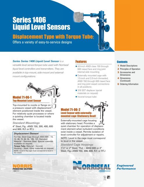
Series 1406 Liquid Level Sensors - Norriseal
Series 1406 Liquid Level Sensors - Norriseal
Series 1406 Liquid Level Sensors - Norriseal

Create successful ePaper yourself
Turn your PDF publications into a flip-book with our unique Google optimized e-Paper software.
<strong>Series</strong> <strong>1406</strong><br />
<strong>Liquid</strong> <strong>Level</strong> <strong>Sensors</strong><br />
Displacement Type with Torque Tube:<br />
Offers a variety of easy-to-service designs<br />
<strong>Series</strong> <strong>Series</strong> <strong>1406</strong> <strong>Liquid</strong> <strong>Level</strong> Sensor is a<br />
versatile level sensor/torque tube used with <strong>Norriseal</strong><br />
liquid level controllers and transmitters. They are<br />
available in top-mount, side-mount and externalmount<br />
configurations.<br />
Model 71-06-1<br />
Top Mounted <strong>Level</strong> Sensor<br />
Top-mounted to nozzle or flange on<br />
a pressure vessel with displacement<br />
element positioned inside the vessel.<br />
For relatively quiet processes or where<br />
a quieting chamber is located inside<br />
the vessel.<br />
Standard Mountings<br />
4” Steel, Fig. -ANSI 150, 300, 400, 600<br />
and 900. R.F. or RTJ<br />
Displacement Element<br />
For Fab. Steel Cage through ANSI 600:–14,<br />
32, 48, 72, 84, 96, 108, 120. Standard<br />
Material – Stainless Steel. Special materials<br />
available on request.<br />
Torque Tube. Material – Inconel,<br />
Housing – Steel. Other materials on request.<br />
NOTE: <strong>Level</strong> in the cage must correspond to level in<br />
the vessel.<br />
Features<br />
4.0-inch ANSI class 150 through<br />
600 raised face and ring joint<br />
internal side mounting<br />
Externally mounted cage with<br />
1.5-inch and 2.0-inch thrreaded,<br />
ANSI 150 through 600 riased face<br />
and ring joint vessel connections<br />
in all positions<br />
316 SST displacer (spcial<br />
materials on request)<br />
Inconel torque tube<br />
Model 71-06-2<br />
<strong>Level</strong> Sensor with externally-<br />
mounted cage (Stationery Head)<br />
Externally-mounted cage housing<br />
with stationary head. Provides a<br />
quiet chamber for operation of displacement<br />
element when turbulent conditions<br />
exist inside a vessel. Permits isolation of<br />
level controller for adjustment or repairs.<br />
NOTE: <strong>Level</strong> in the cage must correspond<br />
to level in the vessel.<br />
Standard Cage Housings<br />
11 ⁄2” or 2” Steel, Thd. – ANSI 600 or 2”<br />
Steel, Fig.–ANSI 150, 300, 600, R.F. or RTJ<br />
ISO 9001<br />
Cert. #30080<br />
Contents<br />
1 Model Descriptions<br />
2 Principles of Operation<br />
3 Accessories and<br />
Dimensions<br />
4 Dimensions<br />
(Continued)<br />
6 Ordering Information<br />
Engineered<br />
Performance
2 Specifications<br />
Model 71-06-3<br />
Side Mounted <strong>Level</strong> Sensor<br />
Side-mounted to nozzle or flange on a<br />
pressure vessel with displacement element<br />
positioned inside the vessel. For relatively quiet<br />
processes or where a quieting chamber is located<br />
inside the vessel. Also used in corrosive applications<br />
where external piping cannot be used or<br />
where external cage mountings are not practical<br />
because of clogging or vapor lock.<br />
Torque arm between displacement element and<br />
torque tube is 20” long, double the length of top<br />
and external mounted units. Displacement<br />
element is correspondingly lighter and displaces<br />
less volume.<br />
NOTE: Special consideration must be given<br />
to installation of long displacements through<br />
vessel opening<br />
Standard Mountings<br />
4” Steel, Fig. -ANSI 150, 300, 400, 600<br />
and 900. R.F. or RTJ<br />
Model 71-06-6<br />
<strong>Level</strong> Sensor with externally-<br />
mounted cage (Rotatable Head)<br />
Externally-mounted cage housing with<br />
rotatable head. Permits upper cage, torque<br />
tube and controller to be rotated on the<br />
float cage for easier accessibility as<br />
required.<br />
Standard Cage Housings<br />
1 1 ⁄2” or 2” Steel, Thd. – ANSI 600 or 11⁄2” or 2”<br />
Steel, Fig.–ANSI 150, 300, 400, 600, R.F. or RTJ<br />
Torque Tube Assembly<br />
Torque tube assembly consists of a shaft inside a tube. Tube is enclosed at the connector block<br />
end, with shaft welded concentrically to end closure of the tube. At the other end, shaft rotates<br />
in a bearing and connects to a specific gravity rocker arm. No stuffing box or packing gland<br />
required in transmitting rotational movement from torque tube to a specific gravity rocker arm.<br />
Torque tube is welded construction. All critical internal parts exposed to process<br />
are either inconel or 316 stainless steel (important for corrosive services).<br />
Displacement arm is reversible for either right or left hand<br />
mounting of controller or transmitter. No additional parts<br />
required for this reversal. Complete dismantling not<br />
required. Symmetrical connector block permits<br />
mounting of torque tube in either end.<br />
Connector block has no bearing parts;<br />
It’s frictionless, free from freezing or<br />
clogging.<br />
Principles of Operation<br />
Displacement element is positioned in liquid to be<br />
measured. As liquid level changes in vessel,<br />
apparent weight of displacement element (due to<br />
fluid displacement) varies according to amount of<br />
its submergence. This change in weight is converted<br />
to variable angular rotation in torque tube<br />
and produces an output pressure from the controller<br />
that is proportional to liquid level. Output<br />
pressure then positions control valve to regulate<br />
and maintain correct liquid level for process.<br />
72-Pneumatic Controller. Specific gravity rocker<br />
arm and proportional bands are set direct for gravity<br />
ranges between 0.5 and 1.5. For gravities above<br />
1.5 or below 0.5, special elements can be used or<br />
necessary compensation made by proportional<br />
band setting.<br />
1600 Electronic Controller. FM and CSA approved<br />
Class I, Div 1 Groups C&D. Gravity ranges same as<br />
72-45. Two-wire loop powered. Available as transmitter<br />
only or transmitter with proportional plus<br />
integral control. Set point, proportional band, and<br />
integral are entered via key pad.<br />
TORQUE<br />
TUBE<br />
CAGE<br />
HOUSING<br />
DISPLACEMENT ELEMENT<br />
CONTROLLER<br />
MOUNTING END<br />
REMOVABLE<br />
PIN<br />
CONNECTOR<br />
BLOCK
3 Accessories and Dimensions<br />
Accessories<br />
Radiation Fin Torque Tube Housing. For service<br />
temperatures below 0° F and above 800° F.<br />
(Standard torque tube housing without insulation<br />
is suitable for 0° F to 800° F service temperatures if<br />
ambient temperature is below 80°F.)<br />
Side-mounted <strong>Level</strong> Controller for Hub Mounting.<br />
20” torque arm, standard. Other lengths available<br />
Dimensions<br />
For Preliminary Piping Design<br />
on special request. Displacement element, stainless<br />
steel, 50 cu. in. Available in ratings of ANSI<br />
1440 and 3600 CWP.<br />
Gage Glass Assemblies. Consult Factory.<br />
71-06-1 Top Mounted <strong>Level</strong> Sensor 71-06-3 Side Mounted <strong>Level</strong> Sensor<br />
TOP VIEW<br />
SIDE VIEW<br />
TOP VIEW<br />
SIDE VIEW<br />
Dimensions (inches)<br />
Displacement Element<br />
Length (inches)<br />
A<br />
Top Mounted<br />
Steel<br />
B<br />
Side Mounted<br />
A<br />
14 8 7 8 1 ⁄4<br />
32 8 16 17 1 ⁄4<br />
48 8 24 25 1 ⁄4<br />
60 8 30 31 1 ⁄4<br />
72 8 36 37 1 ⁄4<br />
84 8 42 43 1 ⁄4<br />
96 8 48 49 1 ⁄4<br />
108 8 54 55 1 ⁄4<br />
120 8 60 61 1 ⁄4
4 Dimensions (Continued)<br />
71-06-2 <strong>Level</strong> Sensor with externally-mounted cage (Stationary Head)<br />
With Threaded Connections With Flanged Connections<br />
MOUNTING 1 MOUNTING 2<br />
MOUNTING 3 MOUNTING 4<br />
TOP VIEW SIDE VIEW<br />
For Mountings 1, 2, 3 and 4 Cast Steel – 1 1 ⁄2” or 2” ANSI 600 lb.<br />
MOUNTING 5 MOUNTING 6<br />
MOUNTING 7 MOUNTING 8<br />
TOP VIEW SIDE VIEW<br />
Displacement<br />
Element Length<br />
Equalizing Connection Dimensions (inches) Mountings 1, 2, 3 and 4<br />
(inches)<br />
A B C D E F<br />
Steel 14 221 ⁄2 161 ⁄2 191 ⁄4 193 ⁄4 101 ⁄2 73 ⁄4<br />
32 417 ⁄8 357 ⁄8 385 ⁄8 391 ⁄8 207 ⁄8 181 ⁄8<br />
48 577 ⁄8 517 ⁄8 545 ⁄8 551 ⁄8 287 ⁄8 261 ⁄8<br />
60 697 ⁄8 637 ⁄8 665 ⁄8 671 ⁄8 347 ⁄8 321 ⁄8<br />
72 817 ⁄8 757 ⁄8 785 ⁄8 791 ⁄8 407 ⁄8 381 ⁄8<br />
84 937 ⁄8 777 ⁄8 905 ⁄8 911 ⁄8 467 ⁄8 441 ⁄8<br />
96 105 7 ⁄8 997 ⁄8 102 5 ⁄8 1031 ⁄8 527 ⁄8 501 ⁄8<br />
108 117 7 ⁄8 111 7 ⁄8 114 5 ⁄8 1151 ⁄8 547 ⁄8 561 ⁄8<br />
120 129 7 ⁄8 123 7 ⁄8 126 5 ⁄8 1271 ⁄8 647 ⁄8 621 ⁄8<br />
For Mountings 5, 6, 7 and 8 Cast Steel – 11 ⁄2” or 2” ANSI 150, 300, 400 and 600 lb. R. F.<br />
Displacement<br />
Element Length<br />
Equalizing Connection Dimensions (inches) Mountings 5, 6, 7 and 8<br />
(inches)<br />
A B C D E F<br />
14 29 161 ⁄2 221 ⁄4 23 13 3 ⁄4 73 ⁄4<br />
32 483 ⁄8 357 ⁄8 417 ⁄8 423 ⁄8 241 ⁄8 181 ⁄8<br />
48 643 ⁄8 517 ⁄8 577 ⁄8 583 ⁄8 321 ⁄8 261 ⁄8<br />
60 763 ⁄8 637 ⁄8 637 ⁄8 703 ⁄8 381 ⁄8 321 ⁄8<br />
72 883 ⁄8 757 ⁄8 817 ⁄8 823 ⁄8 441 ⁄8 381 ⁄8<br />
84 100 3 ⁄8 877 ⁄8 937 ⁄8 943 ⁄8 501 ⁄8 441 ⁄8<br />
96 112 3 ⁄8 997 ⁄8 1057 ⁄8 1063 ⁄8 561 ⁄8 501 ⁄8<br />
108 124 3 ⁄8 111 7 ⁄8 117 7 ⁄8 118 3 ⁄8 621 ⁄8 561 ⁄8<br />
120 136 3 ⁄8 123 7 ⁄8 129 7 ⁄8 130 3 ⁄8 681 ⁄8 621 ⁄8
Dimensions (Continued<br />
71-06-6 <strong>Level</strong> Sensor with externally-mounted cage (Rotatable Head)<br />
With Threaded Connections With Flanged Connections<br />
MOUNTING 9 MOUNTING 10<br />
MOUNTING 11 MOUNTING 12<br />
TOP VIEW TOP VIEW<br />
For Mountings 9 and 10 – 11 Displacement<br />
Element Length<br />
⁄2” or 2” ANSI 600 lb.<br />
Equalizing Connection Dimensions (inches) Mountings 9 and 10<br />
(inches)<br />
A B C D E F J<br />
14 335 ⁄8 18 11 14 4 7 161 ⁄2<br />
32 5211 ⁄16 373 ⁄8 213 ⁄8 32 53 ⁄8 16 357 ⁄8<br />
48 6811 ⁄16 533 ⁄8 293 ⁄8 48 53 ⁄8 24 517 ⁄8<br />
60 8011 ⁄16 653 ⁄8 353 ⁄8 60 53 ⁄8 32 637 ⁄8<br />
72 9211 ⁄16 773 ⁄8 413 ⁄8 72 53 ⁄8 36 757 ⁄8<br />
84 104 11 ⁄16 893 ⁄8 473 ⁄8 84 53 ⁄8 42<br />
96 116 11 ⁄16 1013 ⁄8 533 ⁄8 96 53 ⁄8 48<br />
108 128 11 ⁄16 113 3 ⁄8 593 ⁄8 108 53 ⁄8 54<br />
120 14011 ⁄16 125 3 ⁄8 653 ⁄8 120 53 ⁄8 60<br />
For Mountings 11 and 12 – 11 Displacement<br />
Element Length<br />
⁄2” or 2” ANSI 600 lb. R. F.<br />
Equalizing Connection Dimensions (inches) Mountings 9 and 10<br />
(inches) A B C E F G H J<br />
14 3611 ⁄16 211 ⁄4 141 ⁄4 335 ⁄16 14 4 11 161 ⁄2<br />
32 5515 ⁄16 405 ⁄8 245 ⁄8 5211 ⁄16 32 53 ⁄8 16 357 ⁄8<br />
48 7115 ⁄16 565 ⁄8 325 ⁄8 6811 ⁄16 48 53 ⁄8 24 517 ⁄8<br />
60 8315 ⁄16 565 ⁄8 385 ⁄8 8011 ⁄16 60 53 ⁄8 30 637 ⁄8<br />
72 9515 ⁄16 805 ⁄8 445 ⁄8 9211 ⁄16 72 53 ⁄8 36 757 ⁄8<br />
84 10715 ⁄16 925 ⁄8 505 ⁄8 10411 ⁄16 84 53 ⁄8 42<br />
96 11915 ⁄16 104 5 ⁄8 565 ⁄8 11511 ⁄16 96 53 ⁄8 48<br />
108 131 15 ⁄16 116 5 ⁄8 625 ⁄8 12811 ⁄16 108 53 ⁄8 54<br />
120 14315 ⁄16 1285 ⁄8 685 ⁄8 14011 ⁄16 120 53 ⁄8 60<br />
5
6<br />
1. Model Number:<br />
Top Mounted <strong>Level</strong> Sensor 71-06-1<br />
Side Mounted <strong>Level</strong> Sensor 71- 06-3<br />
<strong>Level</strong> Sensor, externally-mounted<br />
cage with rotatable head 71- 06-6<br />
2. Indicating Controller Electronic<br />
1610 pneumatic 72- 45-1<br />
3. Non-Indicating Controller Electronic 72- 45-1<br />
4. Transmitter Electronic: 1620<br />
5. Cage Housing: Size, Material, Type<br />
ANSI Rating<br />
6. Displacement Element: Length and Material<br />
7. Torque Tube: Material for tube<br />
and housing<br />
Control Signal Output: 3-15, 3-27, 6-30 psi<br />
Ordering Information<br />
©2013 Dover Corporation/<strong>Norriseal</strong> and its affiliates. This manual, including all text and<br />
images, is a copyrighted work of Dover Corporation/<strong>Norriseal</strong> and its affiliates. It may<br />
not be, in whole or in part, photocopied, scanned, or otherwise reproduced, revised,<br />
or publicly displayed, without prior written permission from <strong>Norriseal</strong>. This manual is<br />
for use only with the new <strong>Norriseal</strong> valves and/or controllers listed in the manual. It<br />
may not be distributed with, and is not for use with, any remanufactured products.<br />
Please contact your <strong>Norriseal</strong> representative<br />
for more details and assistance in specifying<br />
the optimal solution for your application.<br />
Engineered Performance<br />
11122 West Little York • Houston, Texas 77041<br />
Tel: 713·466·3552 • Fax: 713·896·7386<br />
www.norriseal.com<br />
8. Accessories: Radiation fin torque tube housing<br />
Gage glass assembly.<br />
(Specify tubular or reflex type)<br />
Side-mounted level controller for<br />
hub mounting. (Specify length of<br />
torque arm and pressure rating)<br />
When ordering 72-45 or 1600<br />
Transmitter/Controller specify:<br />
1. Minimum pressure of instrument available<br />
2. Transmitter ouptup range<br />
3. Receiver type, dial size and model number<br />
4. Availability of 24VDC power source (1600 only)<br />
Due to the continuous improvement program at <strong>Norriseal</strong>, specifications and/or prices<br />
are subject to change without notice or obligation.<br />
All trademarks contained herein are the property of their respective owners.<br />
0<strong>1406</strong>-0113T