R8239 DCC Booster English Only - Hornby
R8239 DCC Booster English Only - Hornby
R8239 DCC Booster English Only - Hornby

You also want an ePaper? Increase the reach of your titles
YUMPU automatically turns print PDFs into web optimized ePapers that Google loves.
Safety Notes<br />
lThis product is not suitable for children under 3 years because of small parts which can present a choking hazard. Some components have functional sharp points and edges.<br />
Handle with care. lThis product is intended for indoor use only. lThe Digital Control system is only to be operated with the <strong>Hornby</strong> recommended transformers. lBefore use<br />
the transformer should be examined for damage to the casing, plug pins and cables. In the event of such damage, the unit should not be used until the transformer is replaced<br />
with a new <strong>Hornby</strong> recommended unit. Never attempt to open the unit yourself. lBefore cleaning any part, disconnect the transformer from the mains electricity supply.<br />
lDo not use liquid for cleaning. lWires without a connecting means are not to be inserted into outlets. lThe output terminals of the transformers must not be connected<br />
directly, or indirectly, to the output of any other mains power supply. lPlease retain these details and the address for future reference.<br />
Guarantee<br />
All <strong>Hornby</strong> products are guaranteed against defects in materials and workmanship for a period of 6 months and <strong>Hornby</strong> Digital electronics for 1 year from the date of purchase.<br />
To qualify for the guarantee, the product must have been used and maintained according to the manufacturers instructions, and will only be covered when used in conjunction<br />
with officially approved <strong>Hornby</strong> accessories and components. While every possible care and attention has been taken by <strong>Hornby</strong> to ensure that the product arrives to you in<br />
pristine condition, we cannot accept liability for any subsequent misuse of the product. It is the responsibility of the consumer to ensure that the product is maintained as per<br />
the servicing details provided.<br />
For reliable programming it is important that the track and wheels of all locomotives and wagons used with the Select Digital system are kept clean. If any defect occurs during<br />
the guarantee period, then the item in the first instance should be returned to the place of original purchase. Alternatively, if any such defect occurs during the period of guarantee,<br />
then please contact your <strong>Hornby</strong> Service dealer for advice. Or, the product (or component), may be forwarded to <strong>Hornby</strong> Hobbies Ltd, carefully packed, with a covering letter<br />
enclosed giving full details to: Repairs Department, <strong>Hornby</strong> Hobbies Ltd, Westwood, Margate, Kent CT9 4JX. UK.<br />
Please include a copy of the original sales document showing the product reference number, date of purchase and from where purchased and any other requested information<br />
relating to the product. Please obtain a Certificate of Posting at the time of despatch.<br />
Exclusions<br />
Subject to the exclusions below, the product will be repaired or replaced free of charge, if the problem is found to be due to either workmanship or materials. The repair/replacement<br />
will be provided as promptly as possible without significant inconvenience to the consumer: lThe fault has been caused or is attributable to mis-use, negligent use or used<br />
contrary to the manufacturers recommendations. lAccidental physical damage. This guarantee is valid for products purchased in the United Kingdom and is in addition to,<br />
and does not diminish, your statutory rights. For further advice about your statutory rights contact your local authority Trading Standards Department or Citizens Advice Bureau.<br />
This warranty only covers <strong>Hornby</strong> manufactured items. Please retain these details and address for future reference.<br />
<strong>Hornby</strong> Hobbies Limited, Margate, Kent CT9 4JX.<br />
Tel: +44 (0) 1843 233525 4/1305<br />
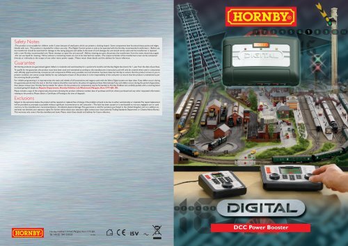
<strong>DCC</strong> Power <strong>Booster</strong>
Introduction<br />
A <strong>Hornby</strong> Digital <strong>Booster</strong> can be fitted to a model railway layout in order to supplement an existing controller<br />
by providing extra track power. The <strong>Hornby</strong> Digital <strong>Booster</strong> can also be used to automatically handle track polarity<br />
reversal when connected to a Reverse Loop or Wye track configurations. The <strong>Hornby</strong> Digital <strong>Booster</strong> will also<br />
boost the digital signal from either a <strong>Hornby</strong> Select, Elite or an alternative controller and may also be linked to<br />
another booster.<br />
A <strong>Hornby</strong> Digital <strong>Booster</strong> is ideal for large layouts which have in the region of 500 plus feet of track however on<br />
exceptionally large layouts it maybe necessary to divide the layout into separate “power areas”. If in doubt consult<br />
your <strong>Hornby</strong> Digital stockist or contact the <strong>Hornby</strong> Helpline.<br />
For more information visit: www.hornby.com<br />
<strong>DCC</strong> Power <strong>Booster</strong><br />
A <strong>DCC</strong> Power <strong>Booster</strong> provides the following functions...<br />
On larger layouts where there is a degradation of the <strong>DCC</strong> signal at extreme distances from the <strong>DCC</strong> controller<br />
it is usual to divide the track into “Electrical Districts” each being driven from a dedicated Power <strong>Booster</strong>. <strong>DCC</strong><br />
signal degradation on very large or complex layouts can still occur even if a ‘Buss’ wiring technique is used to<br />
supply power to the track.<br />
Each Power <strong>Booster</strong> is controlled by taking a <strong>DCC</strong> signal from the Main Controller or from a location on the<br />
track where a good <strong>DCC</strong> signal is present.<br />
Also, Power <strong>Booster</strong>s allow more locos to be run on the same layout. Normally, the number of locomotives that<br />
can be run on any layout will be limited by the maximum current available from the power supply feeding the Main<br />
Controller and its associated <strong>Booster</strong>.<br />
Please Note:<br />
This Main Controller and associated <strong>Booster</strong> are<br />
integrated in the Select and Elite controllers.<br />
If it is desired to run more locos than the limit<br />
governed by the power system of the Main<br />
Controller/<strong>Booster</strong>, then it will become necessary to<br />
divide the layout into isolated “Electrical Districts”<br />
each being driven by its own dedicated Power<br />
<strong>Booster</strong>. This will allow additional locos to be run<br />
in each “Electrical District” up to the maximum<br />
allowed by the power supply used by the “Electrical<br />
District’s” <strong>Booster</strong> unit.<br />
Creating an “Electrical District” and adding a Power<br />
<strong>Booster</strong> to drive it does NOT increase the number<br />
of locos capable of being run in any other district.<br />
The part of the layout making up the first “Electrical<br />
District” is connected to the Main Controller/<strong>Booster</strong>.<br />
This is the “Prime Electrical District”.<br />
Generally the use of Power <strong>Booster</strong>s is dependent on the architecture of the layout and the maximum number of<br />
locos to be run at any one time. i.e. A relatively small layout may contain many “Electrical Districts” if a large number<br />
of locos may be in operation at any one time.<br />
Then again, if you have a large layout you may need to add “Electrical Districts” and Power <strong>Booster</strong>s to ensure the<br />
“quality” of the <strong>DCC</strong> signal at all points of the layout. A complex layout with “fiddle yards” and “long runs” of track<br />
may contain many “Electrical Districts” of different physical sizes or track running lengths.<br />
2
Connecting a <strong>DCC</strong> Power <strong>Booster</strong><br />
Connecting to the Select and Elite using the XpressNet port<br />
Using a <strong>Hornby</strong> R8236 RJ12 cable connect the booster to either of the two XpressNet ports of the Elite<br />
controller or the XpressNet port of the Select.<br />
Fig 1<br />
R 8236 RJ12 Cable<br />
Connecting the Elite using the “Boost” terminals located on the back<br />
of the controller<br />
From PSU<br />
To isolated track<br />
To isolated<br />
To isolated<br />
track 2<br />
3 track 1<br />
4<br />
Connect 2 wires from the “Boost” terminals positioned on the back of the Elite to the terminals on the <strong>Booster</strong>.<br />
Fig 2<br />
To isolated track<br />
For more information visit: www.hornby.com<br />
Next <strong>Booster</strong><br />
From PSU<br />
Next <strong>Booster</strong><br />
Connecting two <strong>Booster</strong>s together<br />
Connect the two output terminals from <strong>Booster</strong> A to the input terminals of <strong>Booster</strong> B.<br />
Fig 3<br />
From Main Controller<br />
Boost Output<br />
Alternative connection<br />
From PSU 1<br />
From PSU 2<br />
If RJ12 Leads, or other suitable flex of sufficient length is not available, the <strong>Booster</strong> can take a Control signal directly<br />
from the track of the main Power area. Connect the Power clips supplied, to the track as shown. The wire from<br />
the main Power area should be connected to “Boost IN”. The wire from the Secondary Power area should be<br />
connected to the “Track” terminals on the <strong>Booster</strong>.<br />
Fig 4<br />
Secondary power area<br />
A<br />
B<br />
Please Note: PSU = Power Supply Unit (Transformer)<br />
A<br />
B<br />
Isolated track<br />
From PSU<br />
Main power area
5<br />
LED Indication<br />
Red LED:<br />
Green LED:<br />
Yellow LED:<br />
Track output short circuit indicator. This light will<br />
indicate that there is either a short circuit or that<br />
the current is over 3 amps. When the red LED<br />
illuminates and the power is cut, switch off the unit<br />
and find the source of the “short”. Once identified,<br />
correct and then switch on. This unit will have<br />
automatically reset itself.<br />
Power “On” indicator.<br />
This is a reverse current indicator which is functional<br />
when the <strong>Booster</strong> is used for Reverse loops or Wye<br />
track configurations. When the track output signal<br />
is reversed from the input signal the yellow LED will<br />
light. Should both the signals be of the same phase<br />
then the yellow LED will not be lit.<br />
For more information visit: www.hornby.com<br />
Notes<br />
For more information visit: www.hornby.com