Target-based Prototyping System Applied to Fuel Control - New Eagle
Target-based Prototyping System Applied to Fuel Control - New Eagle
Target-based Prototyping System Applied to Fuel Control - New Eagle

Create successful ePaper yourself
Turn your PDF publications into a flip-book with our unique Google optimized e-Paper software.
Abstract—A target-<strong>based</strong> rapid pro<strong>to</strong>typing system,<br />
Mo<strong>to</strong>Hawk, is described for controls development, vehicle or<br />
engine calibration, fleet testing and production. Mo<strong>to</strong>Hawk<br />
features the capability of controlling varied types of engines<br />
(gasoline and diesel engines from single-cylinder <strong>to</strong> multicylinder),<br />
au<strong>to</strong>-code generation of Simulink/Stateflow models <strong>to</strong><br />
a family of production Electronic <strong>Control</strong> Units (ECUs), and a<br />
calibration interface incorporated in<strong>to</strong> the models. Finally, an<br />
illustrative example of a Mo<strong>to</strong>Hawk application, the design and<br />
implementation of a fuel control strategy for gasoline engines, is<br />
discussed in detail.<br />
T<br />
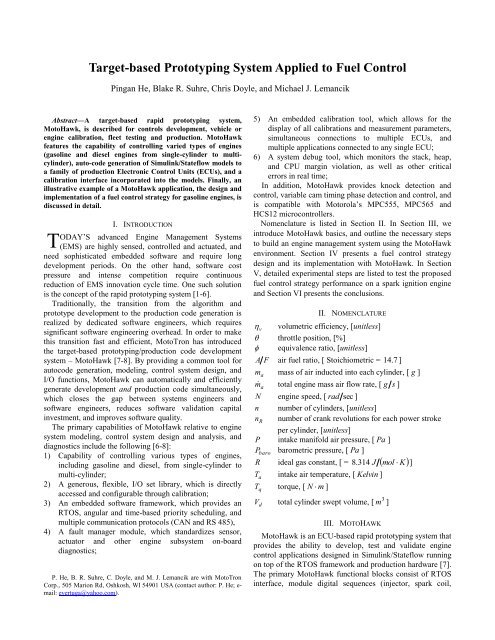
<strong>Target</strong>-<strong>based</strong> <strong>Pro<strong>to</strong>typing</strong> <strong>System</strong> <strong>Applied</strong> <strong>to</strong> <strong>Fuel</strong> <strong>Control</strong><br />
Pingan He, Blake R. Suhre, Chris Doyle, and Michael J. Lemancik<br />
I. INTRODUCTION<br />
ODAY’S advanced Engine Management <strong>System</strong>s<br />
(EMS) are highly sensed, controlled and actuated, and<br />
need sophisticated embedded software and require long<br />
development periods. On the other hand, software cost<br />
pressure and intense competition require continuous<br />
reduction of EMS innovation cycle time. One such solution<br />
is the concept of the rapid pro<strong>to</strong>typing system [1-6].<br />
Traditionally, the transition from the algorithm and<br />
pro<strong>to</strong>type development <strong>to</strong> the production code generation is<br />
realized by dedicated software engineers, which requires<br />
significant software engineering overhead. In order <strong>to</strong> make<br />
this transition fast and efficient, Mo<strong>to</strong>Tron has introduced<br />
the target-<strong>based</strong> pro<strong>to</strong>typing/production code development<br />
system – Mo<strong>to</strong>Hawk [7-8]. By providing a common <strong>to</strong>ol for<br />
au<strong>to</strong>code generation, modeling, control system design, and<br />
I/O functions, Mo<strong>to</strong>Hawk can au<strong>to</strong>matically and efficiently<br />
generate development and production code simultaneously,<br />
which closes the gap between systems engineers and<br />
software engineers, reduces software validation capital<br />
investment, and improves software quality.<br />
The primary capabilities of Mo<strong>to</strong>Hawk relative <strong>to</strong> engine<br />
system modeling, control system design and analysis, and<br />
diagnostics include the following [6-8]:<br />
1) Capability of controlling various types of engines,<br />
including gasoline and diesel, from single-cylinder <strong>to</strong><br />
multi-cylinder;<br />
2) A generous, flexible, I/O set library, which is directly<br />
accessed and configurable through calibration;<br />
3) An embedded software framework, which provides an<br />
RTOS, angular and time-<strong>based</strong> priority scheduling, and<br />
multiple communication pro<strong>to</strong>cols (CAN and RS 485),<br />
4) A fault manager module, which standardizes sensor,<br />
actua<strong>to</strong>r and other engine subsystem on-board<br />
diagnostics;<br />
P. He, B. R. Suhre, C. Doyle, and M. J. Lemancik are with Mo<strong>to</strong>Tron<br />
Corp., 505 Marion Rd, Oshkosh, WI 54901 USA (contact author: P. He; email:<br />
evertuga@yahoo.com).<br />
5) An embedded calibration <strong>to</strong>ol, which allows for the<br />
display of all calibrations and measurement parameters,<br />
simultaneous connections <strong>to</strong> multiple ECUs, and<br />
multiple applications connected <strong>to</strong> any single ECU;<br />
6) A system debug <strong>to</strong>ol, which moni<strong>to</strong>rs the stack, heap,<br />
and CPU margin violation, as well as other critical<br />
errors in real time;<br />
In addition, Mo<strong>to</strong>Hawk provides knock detection and<br />
control, variable cam timing phase detection and control, and<br />
is compatible with Mo<strong>to</strong>rola’s MPC555, MPC565 and<br />
HCS12 microcontrollers.<br />
Nomenclature is listed in Section II. In Section III, we<br />
introduce Mo<strong>to</strong>Hawk basics, and outline the necessary steps<br />
<strong>to</strong> build an engine management system using the Mo<strong>to</strong>Hawk<br />
environment. Section IV presents a fuel control strategy<br />
design and its implementation with Mo<strong>to</strong>Hawk. In Section<br />
V, detailed experimental steps are listed <strong>to</strong> test the proposed<br />
fuel control strategy performance on a spark ignition engine<br />
and Section VI presents the conclusions.<br />
II. NOMENCLATURE<br />
v volumetric efficiency, [unitless]<br />
throttle position, [%]<br />
equivalence ratio, [unitless]<br />
A F air fuel ratio, [ S<strong>to</strong>ichiometric = 14 . 7 ]<br />
m a mass of air inducted in<strong>to</strong> each cylinder, [ g ]<br />
m <strong>to</strong>tal engine mass air flow rate, [ g s ]<br />
a<br />
N engine speed, [ rad sec ]<br />
n number of cylinders, [unitless]<br />
n R number of crank revolutions for each power stroke<br />
per cylinder, [unitless]<br />
P intake manifold air pressure, [ Pa ]<br />
P baro barometric pressure, [ Pa ]<br />
R ideal gas constant, [ = 8 . 314 J mol K<br />
]<br />
T a intake air temperature, [ Kelvin ]<br />
T <strong>to</strong>rque, [ N m ]<br />
q<br />
V <strong>to</strong>tal cylinder swept volume, [ m ]<br />
d<br />
III. MOTOHAWK<br />
Mo<strong>to</strong>Hawk is an ECU-<strong>based</strong> rapid pro<strong>to</strong>typing system that<br />
provides the ability <strong>to</strong> develop, test and validate engine<br />
control applications designed in Simulink/Stateflow running<br />
on <strong>to</strong>p of the RTOS framework and production hardware [7].<br />
The primary Mo<strong>to</strong>Hawk functional blocks consist of RTOS<br />
interface, module digital sequences (injec<strong>to</strong>r, spark coil,<br />
3
variable cam phase, etc.), analog I/O (PWM, wide-band<br />
oxygen sensor, etc.), interface <strong>to</strong> CAN and serial<br />
communications devices, interface <strong>to</strong> the calibration and<br />
display, fault manager definition, engine position (encoder),<br />
and debug <strong>to</strong>ols.<br />
In the following example, a basic engine management<br />
system (EMS) is constructed using Mo<strong>to</strong>Hawk. The <strong>to</strong>p level<br />
Mo<strong>to</strong>Hawk diagram of an EMS is shown in Figure 1. This<br />
EMS consists of an operating system, engine constants,<br />
vehicle and gauge, controller, and engine. Each of these<br />
subsystems will be explained next.<br />
A. Operating <strong>System</strong><br />
The operating system definition block defines the target<br />
hardware, stack size, heap size, and system debug <strong>to</strong>ol. The<br />
target hardware could be, for example, an MPC555,<br />
MPC565, MPC563, HCS12 or other microcontroller-<strong>based</strong><br />
system. Foreground, background, idle and interrupt stack<br />
sizes need <strong>to</strong> be defined for the multi-tasking operating<br />
system. A system debug <strong>to</strong>ol moni<strong>to</strong>rs the stack, heap, and<br />
CPU margin violations or other critical errors in real time. In<br />
any case, when one of these errors is discovered, certain<br />
actua<strong>to</strong>r will be shut down safely, such as fuel injec<strong>to</strong>rs and<br />
spark coils. The operating system can handle event-<strong>based</strong><br />
and/or time-<strong>based</strong> embedded systems and supports both<br />
angle- and time-<strong>based</strong> priority scheduling.<br />
B. Engine Constants<br />
Fig. 1. EMS <strong>to</strong>p level diagram.<br />
Within the engine constants block, global data are defined<br />
and can be used anywhere in the engine management system<br />
model. These constants include but are not limited <strong>to</strong><br />
cylinder displacement, air-fuel ratio, cylinder firing order,<br />
cylinder firing angles, number of crank revolutions for each<br />
power stroke per cylinder, engine type (diesel or gasoline),<br />
etc. All of these constants can be adjusted or changed during<br />
the calibration process.<br />
C. CAN Definition<br />
The communications between driver command, gauges,<br />
calibration, and ECU can be realized by CAN or serial<br />
communications. The CAN definition, transmit blocks, and<br />
receive blocks set up all the communication parameters such<br />
as baud rate, transmit and receive queue size, CAN message<br />
definition, asynchronous or synchronous transmission, etc.<br />
This ensures accurate messages transmission among driver<br />
inputs, gauges, sensors, ECUs, and calibrations.<br />
D. Vehicle and Gauge<br />
The vehicle opera<strong>to</strong>r initiates control commands <strong>to</strong> the<br />
ECU, and the ECU calculates suitable control signals <strong>based</strong><br />
on engine operation conditions and the structure of its<br />
control algorithms. Then the control signal is sent <strong>to</strong><br />
actua<strong>to</strong>rs <strong>to</strong> perform the required task. The gauge gathers and<br />
displays, graphically, engine running parameters such as<br />
RPM, engine coolant temperature, manifold pressure, etc.<br />
E. <strong>Control</strong>ler<br />
The engine controller can be partitioned in<strong>to</strong> several<br />
subsystems: Virtual Sensors, Virtual Commands, Engine<br />
<strong>Control</strong>, Actua<strong>to</strong>r Characterization, and Diagnostics. The<br />
engine controller system diagram is shown in Figure 2. The<br />
structure and function of individual subsystems are outlined<br />
below.<br />
1) Virtual Sensors Subsystem: it receives the sensor and<br />
command signals, and then calculates the Virtual Sensor<br />
signals (such as engine state and normalized effective engine<br />
coolant temperature) <strong>based</strong> on the physical framework,<br />
logical framework and engine operating conditions.<br />
The Virtual Sensor signals are used in all other engine<br />
controller subsystems.<br />
Sensors<br />
Virtual<br />
Sensors<br />
Virtual<br />
Commands<br />
Virtual Sensors<br />
Virtual<br />
Commands<br />
Engine<br />
<strong>Control</strong><br />
<strong>Control</strong><br />
Signals<br />
Virtual Commands<br />
<strong>Control</strong> Signals<br />
Virtual Sensors<br />
Diagnostics<br />
Virtual Sensors Virtual Sensors<br />
Fig. 2. Engine controller system.<br />
Actua<strong>to</strong>r<br />
Characterization<br />
2) Virtual Commands Subsystem: it is used <strong>to</strong> synthesize<br />
the commands from driver <strong>based</strong> on engine models and<br />
sensor signals. It is useful for the Engine <strong>Control</strong> subsystem<br />
and Diagnostics subsystem.<br />
3) Engine <strong>Control</strong> Subsystem: combining Virtual<br />
Commands and Virtual Sensors signals, and <strong>based</strong> on engine<br />
models and control requirements, the Engine <strong>Control</strong><br />
subsystem calculates suitable <strong>to</strong>rque request, fuel, air, spark<br />
advance, spark energy and ignition timing accounting for<br />
engine configuration (naturally aspirated or turbocharged<br />
engines, engines with or without EGR) and different<br />
situations such as warm-up, cruise control, knock control and<br />
emission control. It may include [3, 5, and 9]:<br />
The Engine Torque Coordina<strong>to</strong>r: its function is <strong>to</strong><br />
simplify and integrate multiple <strong>to</strong>rque requests (for<br />
example: driver request, idle control, cruise control and<br />
emission control may simultaneously and independently
make <strong>to</strong>rque requests) placed on the engine as well as<br />
coordinate how that <strong>to</strong>rque is produced (i.e. via air, fuel<br />
or spark). It is only available for engines equipped with<br />
an electronic throttle.<br />
The Air/<strong>Fuel</strong> Coordina<strong>to</strong>r: similar <strong>to</strong> the engine <strong>to</strong>rque<br />
coordina<strong>to</strong>r, all mixture demands are coordinated in one<br />
air/fuel manager. Based on the operating conditions, a<br />
set of basic functions controls the air/fuel ratio within<br />
the physical limits.<br />
Cylinder Individual Knock <strong>Control</strong>: using knock sensors<br />
<strong>to</strong> detect the onset of de<strong>to</strong>nation, retards spark timing on<br />
a per cylinder basis.<br />
Idle Speed Governor: including idle speed control, idle<br />
transition (entry and exit) control, idle spark advance<br />
and air control;<br />
Emissions <strong>Control</strong>: works <strong>to</strong> optimize emissions during<br />
cranking, start and after start. This enables the<br />
realization of various catalyst warm-up strategies.<br />
Additional cus<strong>to</strong>mer defined functions as required.<br />
The engine control subsystem signals are used in<br />
Diagnostics and Actua<strong>to</strong>r Characterization subsystems as<br />
follows.<br />
4) Actua<strong>to</strong>r Characterization: including injec<strong>to</strong>r<br />
characterization, spark coils characterization, electronic<br />
throttle characterization, etc. It receives signals from Virtual<br />
Sensors and Engine <strong>Control</strong> subsystems and sends out<br />
signals <strong>to</strong> the engine actua<strong>to</strong>rs.<br />
5) Diagnostics: including all the sensors, actua<strong>to</strong>rs and<br />
catalyst diagnostics. The Diagnostics subsystem receives<br />
signals from Virtual Sensors, Virtual Commands and the<br />
Engine <strong>Control</strong> subsystems, and interfaces with calibrations,<br />
SCAN-<strong>to</strong>ols, and audio-visual devices.<br />
F. Engine<br />
In terms of engine control, the Engine portion of the model<br />
consists of Sensors and Actua<strong>to</strong>rs. The Sensors section<br />
<strong>Target</strong> <br />
<br />
<br />
Perturbation<br />
Function<br />
<strong>Fuel</strong><br />
<strong>Control</strong><br />
Enable<br />
MAF<br />
Sensor<br />
Delay<br />
<br />
<br />
Measured<br />
<br />
O2 Sensors<br />
Driver TPS Request<br />
<br />
O2 Sensor<br />
Diagnostics<br />
<br />
TPS<br />
MAF<br />
MAF<br />
Error<br />
MAF<br />
Error<br />
FF<br />
<strong>Control</strong>ler<br />
I Term<br />
Adaptation<br />
PID<br />
receives electronic signals from the physical sensors or<br />
engine model at the hardware pins and then converts them<br />
in<strong>to</strong> suitable engine units for computation in the <strong>Control</strong>ler.<br />
It also includes signal conditioning and filtering. The<br />
Actua<strong>to</strong>rs section links the signal from Actua<strong>to</strong>r<br />
Characterization subsystem <strong>to</strong> the correct hardware pins. The<br />
Sensors and Actua<strong>to</strong>rs can be in subsystems running at<br />
different update rates.<br />
To be capable of controlling different engines with the<br />
same engine model, a universal encoder block, injec<strong>to</strong>r<br />
sequence block and spark sequence block are included in<br />
Mo<strong>to</strong>Hawk. The injec<strong>to</strong>r sequence sets up a sequence of<br />
injection pulses, starting with the specified pin and working<br />
up. It can accommodate up <strong>to</strong> 12 either high-impedance or<br />
low-impedance injec<strong>to</strong>rs. Similar <strong>to</strong> the injec<strong>to</strong>r sequence,<br />
the spark sequence sets up a sequence of spark pulses<br />
dynamically, starting with the specified pin and working up.<br />
The Mo<strong>to</strong>Hawk encoder block supports different Crank/Cam<br />
sensor combinations and the mechanical vs. electrical offset<br />
can also be adjusted at runtime. This means the same,<br />
already-developed, engine model and control algorithm can<br />
be code-generated once and the binary executable file can be<br />
used for different engines with different encoder types,<br />
number of cylinders, firing order, sensor inputs, and driver<br />
outputs. By doing this, the software development time is<br />
greatly reduced.<br />
After introducing the basics of Mo<strong>to</strong>Hawk and the<br />
construction of an engine management system in this section,<br />
a fuel control strategy is proposed in the following section.<br />
IV. FUEL CONTROL DESIGN<br />
To meet stringent engine emissions requirements and<br />
increase fuel economy, a model-<strong>based</strong> adaptive and<br />
feedforward fuel control strategy is proposed for gasoline<br />
engines. The controller structure is shown in Figure 3.<br />
Gain<br />
Scheduling<br />
ETC<br />
<strong>Control</strong>ler<br />
TPS<br />
Sensor<br />
Fig. 3. <strong>Fuel</strong> controller structure.<br />
<br />
<br />
<br />
<br />
CTRL Output<br />
Knock<br />
<strong>Fuel</strong><br />
<strong>Control</strong>ler<br />
Gasoline<br />
Engine<br />
<strong>Fuel</strong><br />
Calculation<br />
<strong>Fuel</strong><br />
Injec<strong>to</strong>rs<br />
Other<br />
Actua<strong>to</strong>rs
The model-<strong>based</strong> design centers around a physical plant<br />
model. Being a feedforward-<strong>based</strong> design, the model is used<br />
<strong>to</strong> predict engine state <strong>based</strong> on current sensor inputs. This<br />
provides more responsive control. The adaptive portion of<br />
the design uses feedback signals from engine sensors and<br />
actua<strong>to</strong>rs <strong>to</strong> adapt the engine model thus minimizing the<br />
amount of control done in the feedback portion of the loop.<br />
These three parts are necessary for a stable and robust engine<br />
controller and are widely used in every major Mo<strong>to</strong>Hawk<br />
project.<br />
The fuel control algorithm outlined below is integrated<br />
in<strong>to</strong> the engine management system <strong>to</strong> apply the appropriate<br />
amount of fuel and determines the resulting air/fuel ratio.<br />
The fuel controller is comprised of five subsystems as shown<br />
in Figure 3:<br />
1) <strong>Fuel</strong> <strong>Control</strong> Enable Subsystem: logic <strong>to</strong> decide whether<br />
the strategy is enabled or disabled..<br />
2) Feedforward (FF) <strong>Control</strong> Subsystem: <strong>to</strong> deal with<br />
difficult engine transients;<br />
3) Gain-Scheduled PID <strong>Control</strong> Subsystem: is provided <strong>to</strong><br />
reduce instantaneous A/F errors;<br />
4) Long-Term PID Integration-Term (I-term) Adaptation<br />
Subsystem: <strong>to</strong> adapt <strong>to</strong> changing engine parameters<br />
(such as combustion chamber and inlet tract deposits<br />
and oxygen sensor aging);<br />
5) Oxygen Sensor Diagnostics Subsystem: for the<br />
indication of oxygen sensor operational status.<br />
The control objective is <strong>to</strong> track the delayed perturbed<br />
target equivalence ratio <strong>to</strong> realize optimal emissions system<br />
performance. The s<strong>to</strong>ichiometric equivalence ratio is first<br />
perturbed with specific amplitude and switching frequency.<br />
Then the perturbed equivalence ratio passes through a delay<br />
block. The error input <strong>to</strong> the PID is obtained by comparing<br />
the delayed, perturbed equivalence ratio with the measured<br />
equivalence ratio from oxygen sensors. The final output of<br />
the fuel controller is the sum of PID output, the feedforward<br />
control output and I-term adaptation. Then the output of the<br />
fuel controller goes <strong>to</strong> the fuel calculation block <strong>to</strong> compute<br />
the correct amount of fuel <strong>to</strong> inject. The air ingested by the<br />
engine is controlled by a separate electronic throttle<br />
controller.<br />
Next, the control strategy development is explained in<br />
detail.<br />
A. <strong>Fuel</strong> <strong>Control</strong>ler Enable Logic<br />
<strong>Fuel</strong> closed-loop control is enabled when all the following<br />
conditions are satisfied:<br />
1) <strong>Fuel</strong> control enable flag is set via calibration;<br />
2) Engine indicated work is above a calibrated value<br />
indicating oxygen sensor warm-up;<br />
3) Desired equivalence ratio is within a calibrated range of<br />
s<strong>to</strong>ichiometric;<br />
4) There is no oxygen sensor or catalyst fault;<br />
5) There is no other engine sensor or actua<strong>to</strong>r faults;<br />
B. <strong>Target</strong> Equivalence Ratio<br />
It has been shown that commercially available Three-Way-<br />
Catalysts (TWC) show a significant improvement in<br />
conversion rates when the equivalence ratio oscillates around<br />
the nominal value of 1.0 [10-11]. The ideal equivalence ratio<br />
for the fuel controller is the nominal value of 1.0 oscillated<br />
with a calibratable switching period of T and amplitude <br />
depending on the engine operating conditions, as shown in<br />
Figure 4.<br />
<br />
<br />
Fig. 4. <strong>Target</strong> equivalence ratio<br />
<strong>Target</strong> Equivalence Ratio<br />
S<strong>to</strong>ichiometric 1<br />
Another key fac<strong>to</strong>r in successfully implementing the fuel<br />
control strategy is <strong>to</strong> include a pure measurement delay,<br />
which is composed of fuel transport delay plus the oxygen<br />
sensors’ reaction time. The fuel transport delay consists of<br />
the time from when the fuel command is issued <strong>to</strong> the<br />
injec<strong>to</strong>r <strong>to</strong> the time the exhaust valve opens, and the time for<br />
the gas <strong>to</strong> move from the exhaust port <strong>to</strong> the oxygen sensor<br />
[12]. The pure measurement delay introduces a limitation on<br />
the system bandwidth and limits the transient accuracy of the<br />
system response. For this implementation, we not only<br />
introduce a feedforward term <strong>to</strong> make the controller act<br />
quickly, but delay the target equivalence ratio <strong>to</strong> match with<br />
the pure measurement delay. This is realized by passing<br />
target equivalence ratio through a measurement delay block<br />
before comparing it with the equivalence ratio signal from<br />
the oxygen sensors, as shown in Figure 3. The measurement<br />
delay block consists of a look-up table <strong>based</strong> on the mass of<br />
air flow sensor input. The idea is <strong>to</strong> use the mass air flow<br />
input instead of speed and load <strong>to</strong> reduce the calibration<br />
effort. The mass air flow rate can be obtained from a digital<br />
MAF sensor or via the speed-density calculation [13-14].<br />
A lower MAF value usually means a lower speed and load,<br />
and larger measurement delay. So the transport delay block<br />
is able <strong>to</strong> take in account different engine operation<br />
conditions.<br />
C. Feedforward <strong>Control</strong>ler<br />
The feedforward controller’s reacts instantaneously <strong>to</strong><br />
engine transients and the measurement delay. Based on the<br />
knowledge of engine behavior, combined with current engine<br />
operating conditions (speed and load), the feedforward<br />
controller ‘predicts’ a response that will allow the engine<br />
operate optimally during transient operation and reduce the<br />
reliance on the feedback, PID controller loop.<br />
D. Gain Scheduled PID<br />
To eliminate any instantaneous equivalence ratio error, a<br />
feedback PID controller is introduced. To adapt <strong>to</strong> different<br />
operating conditions (speed and load), a gain scheduled<br />
strategy is proposed as shown in Figure 3. Based on different<br />
values of mass air flow rate, the PID controller parameters<br />
are adjusted accordingly for better performance. The PID<br />
parameters are grouped in a calibrated table and s<strong>to</strong>red in<br />
EEPROM.
E. Long Term PID I-term Adaptation<br />
To reduce the PID controller loading and adapt <strong>to</strong> changes<br />
in engine characteristics, such as oxygen sensor aging, a<br />
long-term PID Integration-term (I-term) adaptation is<br />
included in the fuel controller structure. The principle used<br />
in this I-term adaptation is: with a well-calibrated, gainscheduled,<br />
PID controller, plus a feedforward controller, the<br />
integration term of the PID controller should be small. If the<br />
engine characteristics change over time, the I-term will<br />
absorb any error caused by these changes. This<br />
“accumulated” error in the integration term will then be used<br />
<strong>to</strong> adapt part of the feedforward model, in this case the<br />
injec<strong>to</strong>r model. By doing so, the I-term in the PID controller<br />
will be continuously driven <strong>to</strong>ward zero.<br />
F. Oxygen Sensor Diagnostics<br />
Oxygen sensor diagnostics consist of: enable logic, sensor<br />
voltage moni<strong>to</strong>r, sensor response moni<strong>to</strong>r, and diagnostics<br />
interface.<br />
1) Oxygen sensor enable logic: the oxygen sensor voltage<br />
and response moni<strong>to</strong>rs are primarily enabled during fuel<br />
closed-loop control. The enable logic is duplicated for<br />
each moni<strong>to</strong>r <strong>to</strong> provide different speed/load and enable<br />
conditions via calibration. The rationale for the different<br />
enable conditions is that the oxygen sensor must be<br />
cycling in a well controlled manner <strong>to</strong> perform some of<br />
the response tests, whereas this is not the case for the<br />
voltage tests.<br />
2) Oxygen sensor voltage moni<strong>to</strong>r: it detects a low or high<br />
voltage output from oxygen sensor during fuel closedloop<br />
control;<br />
3) Oxygen sensor response moni<strong>to</strong>r: it detects either a slow<br />
sensor output transition or a slow-<strong>to</strong>-respond sensor;<br />
4) Diagnostics interface: the fault manager contained in<br />
Mo<strong>to</strong>Hawk defines and manages the oxygen sensor fault<br />
and supports the OBD scan <strong>to</strong>ol pro<strong>to</strong>col.<br />
V. EXPERIMENT<br />
This section is <strong>to</strong> validate the proposed fuel control<br />
performance. The control objective is <strong>to</strong> have the measured<br />
equivalence ratio track the target equivalence ratio. In the<br />
section IV, the target equivalence ratio is a square wave as<br />
shown in Figure 4. Since there is no way <strong>to</strong> exactly track a<br />
step response, the target equivalence ratio of the square wave<br />
is passed through a low-pass filter, which results in a more<br />
realistic target equivalence ratio. The switching period T and<br />
amplitude were set at 4 seconds and 0.04, respectively.<br />
Two different scenarios are considered: 1) different<br />
operation regimes: the engine is operated at different speeds<br />
and loads <strong>to</strong> test the controller performance; 2) with or<br />
without delay compensation: the engine is operated at<br />
RPM 1000<br />
with measurement delay compensation or<br />
without delay compensation (both cases without load). In<br />
each scenario, target equivalence ratio and measured<br />
equivalence ratio are plotted <strong>to</strong>gether <strong>to</strong> show the tracking<br />
ability of the proposed fuel controller.<br />
The engine is a GM V-8 of 5.0 liter displacement with an<br />
electronic throttle and a dynamometer <strong>to</strong> control engine load.<br />
Two NGK Universal Exhaust Gas Oxygen (UEGO) sensors<br />
are used <strong>to</strong> measure the equivalence ratio in the exhaust<br />
stream. The hardware platform is the Mo<strong>to</strong>Tron MPC565<strong>based</strong><br />
128-pin module [7]. ECU565-128 is operated at<br />
56MHz and has dual CAN 2.0B data-links, one of which is<br />
reserved for communication <strong>to</strong> the calibration <strong>to</strong>ol. In<br />
addition there is one RS485 serial bus and one ISO 9141<br />
channel. This ECU can accommodate up <strong>to</strong> 34 analog inputs,<br />
8 low frequency digital inputs, two wide-range oxygen<br />
sensor inputs, and two wide-band knock sensors. It also has<br />
12 injec<strong>to</strong>r drivers, three H-Bridge drivers, up <strong>to</strong> 10 low-side<br />
PWMs, and one main power relay driver.<br />
In following each plot, the horizontal axis is time and<br />
represents a 20 second period, the vertical axis is<br />
equivalence ratio and ranges from 0.95 <strong>to</strong> 1.05. The solid<br />
and curved lines are the target and measured equivalence<br />
ratio, respectively.<br />
A. Different Engine Operating Regimes<br />
In this scenario the controller performance is tested at<br />
different engine operating points (speeds and loads). The<br />
measured equivalence ration and target equivalence ratio are<br />
recorded for comparison. Figure 5 shows the controller<br />
performance at RPM 1110<br />
and a brake <strong>to</strong>rque of<br />
44. 5 N m . At this operating point, m a 20.<br />
39 g s ,<br />
manifold pressure is 50 . 8 KPa, throttle position ( ) is<br />
8 . 76 % . The measurement delay compensation is<br />
0. 24 seconds.<br />
Equivalence Ratio<br />
Equivalence Ratio<br />
0 5 10 15<br />
Time (S)<br />
Fig. 5. <strong>Control</strong>ler performance at low speed and load.<br />
0 5 10 15<br />
Time (S)<br />
Fig. 6. <strong>Control</strong>ler performance at high speed and load.
Figure 6 shows the controller performance at<br />
RPM 1220<br />
, a brake <strong>to</strong>rque of 162 . 2 N m ,<br />
m a 32.<br />
3 g s , a manifold pressure of MAP 68.<br />
6 KPa,<br />
and throttle position of 13.<br />
5 % . The measurement delay<br />
compensation is 0.14 seconds.<br />
Comparing the measurement delay at two cases, an<br />
important conclusion can be made: as expected, the<br />
measurement delay at a high speed and load point is less than<br />
that at a low speed and load point.<br />
Obviously, both plots show the fuel controller <strong>to</strong> have<br />
good performance under different engine operating<br />
conditions.<br />
B. With or Without Delay Compensation<br />
The delay compensation block is enabled or disabled in<br />
order <strong>to</strong> compare the controller performance with or without<br />
delay compensation. Figure 7 shows the controller<br />
performance at RPM 1000<br />
, m a 11.<br />
1 g s , manifold<br />
pressure of MAP 36.<br />
6 KPa, throttle position of<br />
5.<br />
1%<br />
. The measurement delay compensation is 0.34<br />
second. From Figure 7, the measured equivalence ratio<br />
tracks the target very well. Figure 8 shows the controller<br />
performance under the same engine operating conditions and<br />
controller configuration except that the delay compensation<br />
subsystem is disabled. Figure 8 confirms that there is a pure<br />
delay between the measured signal and target signal.<br />
Equivalence Ratio<br />
Equivalence Ratio<br />
0 5 10 15<br />
Time (S)<br />
Fig. 7. <strong>Control</strong>ler performance with delay compensation.<br />
0 5 10 15<br />
Time (S)<br />
Fig. 8. <strong>Control</strong>ler performance without delay compensation.<br />
VI. CONCLUSION<br />
This paper presents an ECU-<strong>based</strong> rapid pro<strong>to</strong>typing<br />
system, Mo<strong>to</strong>Hawk, in this case used for engine management<br />
control system design, calibration, and development. It has<br />
the benefits of simpler and faster software development<br />
through the use of production ECU hardware in<br />
development, a transparent environment for software/system<br />
integration which reduces validation time and cost, and<br />
extensibility <strong>to</strong> a flexible family of products. Engine fuel<br />
control was discussed as an illustrative example of a<br />
Mo<strong>to</strong>Hawk application.<br />
ACKNOWLEDGEMENT<br />
The authors would like <strong>to</strong> thank Eric Bradley at Mo<strong>to</strong>Tron<br />
Corp. for the development of the Mo<strong>to</strong>Hawk concept, Aaron<br />
J. Ward at Mo<strong>to</strong>Tron Corp. for implementing and testing<br />
parts of the fuel control strategy and Mark Frank and Patrick<br />
McCarthy at FEV Engine Technology Inc. for many helpful<br />
discussions and suggestions regarding the development of<br />
the fuel control strategy.<br />
REFERENCES<br />
[1] C. Cao, D. Shull, and E. Himes, “A model-<strong>based</strong> environment for<br />
production engine management system (EMS) development,” SAE<br />
paper No. 2001-01-0554, 2001.<br />
[2] S. Furry, and J. Kainz, “Rapid algorithm development <strong>to</strong>ols applied <strong>to</strong><br />
engine management systems,” SAE paper No. 980799, 1998.<br />
[3] J. Gerhardt, H. Honninger and H. Bischof, “A new approach <strong>to</strong><br />
functional and software structure for engine management systems –<br />
Bosch ME7,” SAE Paper No. 980801, 1998.<br />
[4] R. Lawrie and M. McKenna, “An architecture <strong>based</strong> design process<br />
for deploying control software on production hardware using<br />
Mo<strong>to</strong>Hawk,” SAE Paper No. 2003-02-0853, 2003.<br />
[5] B. Mencher, H. Jessen, L. Kaiser, and J. Gerhardt, “Preparing for<br />
CARTRONIC – interface and new strategies for <strong>to</strong>rque coordination<br />
and conversion in a spark ignition engine-management system,” SAE<br />
Paper No. 2001-01-0268, 2001.<br />
[6] J. D. Naber, E. K. Bradley, and J. E. Szpytman, “<strong>Target</strong> <strong>based</strong> rapid<br />
pro<strong>to</strong>typing control system for engine research,” SAE paper No. 2006-<br />
01-0267, 2006.<br />
[7] Mo<strong>to</strong>Tron Corp., web site, www.mo<strong>to</strong>tron.com.<br />
[8] Mo<strong>to</strong>Hawk web site, www.mo<strong>to</strong>hawk.info.<br />
[9] Bosch Gasoline Engine Management Handbook, Robert Bosch<br />
GmbH, 2004.<br />
[10] L. Padeste, Three-Way Catalysts in a Hybrid Drive-<strong>System</strong>:<br />
Experimental Study and Kinetic Modeling, ETH-Dissertation No.<br />
10515, Swiss Federal Institute of Technology (ETH), 1994.<br />
[11] L. Guzzela, “Models and model-<strong>based</strong> control of IC-engines - a<br />
nonlinear approach,” SAE Paper No. 950844, 1995.<br />
[12] J. L. Kainz and J. C. Smith, “Individual cylinder fuel control with a<br />
switching oxygen sensor,” SAE Paper No. 1999-01-0546, 1999.<br />
[13] B. R. Suhre, Mo<strong>to</strong>Tron Engine <strong>Control</strong> and Calibration Basics,<br />
Mo<strong>to</strong>Tron technical report, 2005.<br />
[14] J. B. Heywood, Internal Combustion Engine Fundamentals,<br />
McGraw-Hill Book Company, 1988.