Digital Video Recorder, H.264 Models: DMR-5008/500 (8-Channel ...
Digital Video Recorder, H.264 Models: DMR-5008/500 (8-Channel ...
Digital Video Recorder, H.264 Models: DMR-5008/500 (8-Channel ...

You also want an ePaper? Increase the reach of your titles
YUMPU automatically turns print PDFs into web optimized ePapers that Google loves.
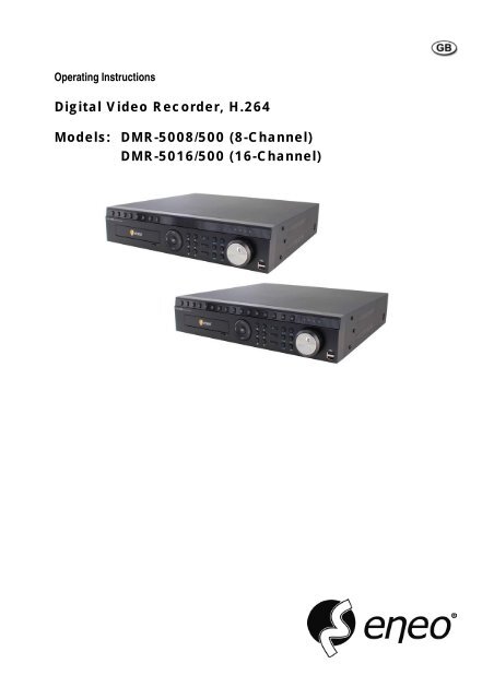
Operating Instructions<br />
<strong>Digital</strong> <strong>Video</strong> <strong>Recorder</strong>, <strong>H.264</strong><br />
<strong>Models</strong>: <strong>DMR</strong>-<strong><strong>500</strong>8</strong>/<strong>500</strong> (8-<strong>Channel</strong>)<br />
<strong>DMR</strong>-5016/<strong>500</strong> (16-<strong>Channel</strong>)
WARNING<br />
RISK OF ELECTRIC SHOCK<br />
DO NOT OPEN<br />
WARNING: TO REDUCE THE RISK OF ELECTRIC SHOCK,<br />
DO NOT REMOVE COVER (OR BACK).<br />
NO USER-SERVICEABLE PARTS INSIDE.<br />
REFER SERVICING TO QUALIFIED<br />
SERVICE PERSONNEL.<br />
<strong>Digital</strong> <strong>Video</strong> <strong>Recorder</strong><br />
The lightning flash with arrowhead symbol, within an equilateral triangle, is intended to alert<br />
the user to the presence of uninsulated "dangerous voltage" within the product’s enclosure<br />
that may be of sufficient magnitude to constitute a risk of electric shock.<br />
The exclamation point within an equilateral triangle is intended to alert the user to the presence<br />
of important operating and maintenance (servicing) instructions in the literature accompanying<br />
the appliance.<br />
COMPLIANCE NOTICE OF FCC:<br />
THIS EQUIPMENT HAS BEEN TESTED AND FOUND TO COMPLY WITH THE LIMITS FOR A CLASS A DIGITAL<br />
DEVICE, PURSUANT TO PART 15 OF THE FCC RULES. THESE LIMITS ARE DESIGNED TO PROVIDE<br />
REASONABLE PROTECTION AGAINST HARMFUL INTERFERENCE WHEN THE EQUIPMENT IS OPERATED IN<br />
A COMMERCIAL ENVIRONMENT. THIS EQUIPMENT GENERATES, USES, AND CAN RADIATE RADIO<br />
FREQUENCY ENERGY AND IF NOT INSTALLED AND USED IN ACCORDANCE WITH THE INSTRUCTION<br />
MANUAL, MAY CAUSE HARMFUL INTERFERENCE TO RADIO COMMUNICATIONS. OPERATION OF THIS<br />
EQUIPMENT IN A RESIDENTIAL AREA IS LIKELY TO CAUSE HARMFUL INTERFERENCE, IN WHICH CASE<br />
USERS WILL BE REQUIRED TO CORRECT THE INTERFERENCE AT THEIR OWN EXPENSE.<br />
WARNING: CHANGES OR MODIFICATIONS NOT EXPRESSLY APPROVED BY THE PARTY RESPONSIBLE FOR<br />
COMPLIANCE COULD VOID THE USER’S AUTHORITY TO OPERATE THE EQUIPMENT.<br />
THIS CLASS OF DIGITAL APPARATUS MEETS ALL REQUIREMENTS OF THE CANADIAN INTERFERENCE-<br />
CAUSING EQUIPMENT REGULATIONS.<br />
The information in this manual is believed to be accurate as of the date of publication. We are not responsible for any<br />
problems resulting from the use thereof. The information contained herein is subject to change without notice. Revisions<br />
or new editions to this publication may be issued to incorporate such changes.<br />
The software included in this product contains some Open Sources. You may obtain the complete corresponding source<br />
code from us. See the Open Source Guide on the software CD (OpenSourceGuide\OpenSourceGuide.pdf) or as a printed<br />
document included along with the User's Manual.<br />
i
ii<br />
User’s Manual<br />
Important Safeguards<br />
1. Read Instructions<br />
All the safety and operating instructions should be read before the<br />
appliance is operated.<br />
2. Retain Instructions<br />
The safety and operating instructions should be retained for future<br />
reference.<br />
3. Cleaning<br />
Unplug this equipment from the wall outlet before cleaning it. Do not<br />
use liquid aerosol cleaners. Use a damp soft cloth for cleaning.<br />
4. Attachments<br />
Never add any attachments and/or equipment without the approval of<br />
the manufacturer as such additions may result in the risk of fire, electric<br />
shock or other personal injury.<br />
5. Water and/or Moisture<br />
Do not use this equipment near water or in contact with water.<br />
6. Ventilation<br />
Place this equipment only in an upright position. This equipment has an<br />
open-frame Switching Mode Power Supply (SMPS), which can cause a<br />
fire or electric shock if anything is inserted through the ventilation holes<br />
on the side of the equipment.<br />
7. Accessories<br />
Do not place this equipment on an unstable cart, stand or table. The<br />
equipment may fall, causing serious injury to a child or adult, and<br />
serious damage to the equipment. Wall or shelf mounting should follow<br />
the manufacturer's instructions, and should use a mounting kit approved<br />
by the manufacturer.<br />
This equipment and cart combination should be moved with care. Quick<br />
stops, excessive force, and uneven surfaces may cause the equipment<br />
and cart combination to overturn.<br />
8. Power Sources<br />
This equipment should be operated only from the type of power source<br />
indicated on the marking label. If you are not sure of the type of power,<br />
please consult your equipment dealer or local power company.<br />
9. Power Cords<br />
Operator or installer must remove power and TNT connections before<br />
handling the equipment.<br />
10. Lightning<br />
For added protection for this equipment during a lightning storm, or when<br />
it is left unattended and unused for long periods of time, unplug it from the<br />
wall outlet and disconnect the antenna or cable system. This will prevent<br />
damage to the equipment due to lightning and power-line surges.<br />
11. Overloading<br />
Do not overload wall outlets and extension cords as this can result in the<br />
risk of fire or electric shock.<br />
12. Objects and Liquids<br />
Never push objects of any kind through openings of this equipment as they<br />
may touch dangerous voltage points or short out parts that could result in a<br />
fire or electric shock. Never spill liquid of any kind on the equipment.<br />
13. Servicing<br />
Do not attempt to service this equipment yourself. Refer all servicing to<br />
qualified service personnel.<br />
WEEE (Waste Electrical & Electronic Equipment)<br />
14. Damage requiring Service<br />
Unplug this equipment from the wall outlet and refer servicing to<br />
qualified service personnel under the following conditions:<br />
A. When the power-supply cord or the plug has been damaged.<br />
B. If liquid is spilled, or objects have fallen into the equipment.<br />
C. If the equipment has been exposed to rain or water.<br />
D. If the equipment does not operate normally by following the operating<br />
instructions, adjust only those controls that are covered by the operating<br />
instructions as an improper adjustment of other controls may result in<br />
damage and will often require extensive work by a qualified technician<br />
to restore the equipment to its normal operation.<br />
E. If the equipment has been dropped, or the cabinet damaged.<br />
F. When the equipment exhibits a distinct change in performance ─ this<br />
indicates a need for service.<br />
15. Replacement Parts<br />
When replacement parts are required, be sure the service technician has<br />
used replacement parts specified by the manufacturer or that have the same<br />
characteristics as the original part. Unauthorized substitutions may result<br />
in fire, electric shock or other hazards.<br />
16. Safety Check<br />
Upon completion of any service or repairs to this equipment, ask the service<br />
technician to perform safety checks to determine that the equipment is in<br />
proper operating condition.<br />
17. Field Installation<br />
This installation should be made by a qualified service person and<br />
should conform to all local codes.<br />
18. Correct Batteries<br />
Warning: Risk of explosion if battery is replaced by an incorrect type.<br />
Dispose of used batteries according to the instructions.<br />
19. Tmra<br />
A manufacturer’s maximum recommended ambient temperature (Tmra)<br />
for the equipment must be specified so that the customer and installer may<br />
determine a suitable maximum operating environment for the equipment.<br />
20. Elevated Operating Ambient Temperature<br />
If installed in a closed or multi-unit rack assembly, the operating ambient<br />
temperature of the rack environment may be greater than room ambient.<br />
Therefore, consideration should be given to installing the equipment in an<br />
environment compatible with the manufacturer’s maximum rated ambient<br />
temperature (Tmra).<br />
21. Reduced Air Flow<br />
Installation of the equipment in the rack should be such that the amount<br />
of airflow required for safe operation of the equipment is not compromised.<br />
22. Mechanical Loading<br />
Mounting of the equipment in the rack should be such that a hazardous<br />
condition is not caused by uneven mechanical loading.<br />
23. Circuit Overloading<br />
Consideration should be given to connection of the equipment to supply<br />
circuit and the effect that overloading of circuits might have on over current<br />
protection and supply wiring. Appropriate consideration of equipment<br />
nameplate ratings should be used when addressing this concern.<br />
24. Reliable Earthing (Grounding)<br />
Reliable grounding of rack mounted equipment should be maintained.<br />
Particular attention should be given to supply connections other than direct<br />
connections to the branch circuit (e.g., use of power strips).<br />
Correct Disposal of This Product<br />
(Applicable in the European Union and other European countries with separate collection systems)<br />
This marking shown on the product or its literature, indicates that it should not be disposed with other household wastes at the<br />
end of its working life. To prevent possible harm to the environment or human health from uncontrolled waste disposal, please<br />
separate this from other types of wastes and recycle it responsibly to promote the sustainable reuse of material resources.<br />
Household users should contact either the retailer where they purchased this product, or their local government office, for<br />
details of where and how they can take this item for environmentally safe recycling.<br />
Business users should contact their supplier and check the terms and conditions of the purchase contract. This product should<br />
not be mixed with other commercial wastes for disposal.
Table of Contents<br />
<strong>Digital</strong> <strong>Video</strong> <strong>Recorder</strong><br />
Chapter 1 — Introduction .........................................................................................................1<br />
Feature ................................................................................................................................1<br />
Technical Overview..............................................................................................................1<br />
Chapter 2 — Installation...........................................................................................................3<br />
Package Contents................................................................................................................3<br />
Required Installation Tools...................................................................................................3<br />
<strong>Video</strong> Input ......................................................................................................................3<br />
<strong>Video</strong> Loop Through ........................................................................................................4<br />
Factory Reset Switch.......................................................................................................4<br />
HD/SD Out Selector.........................................................................................................4<br />
Network Port....................................................................................................................4<br />
iSCSI Port........................................................................................................................4<br />
eSATA Port......................................................................................................................5<br />
RS232C Port....................................................................................................................5<br />
RS485 Port ......................................................................................................................5<br />
Alarm Input/Output...........................................................................................................5<br />
Audio In/Out.....................................................................................................................6<br />
<strong>Video</strong> Out.........................................................................................................................6<br />
Power Cord Connector ....................................................................................................7<br />
Chapter 3 — Configuration.......................................................................................................8<br />
Front Panel Controls ............................................................................................................8<br />
Camera Buttons (1 to 16).................................................................................................9<br />
Enter Button.....................................................................................................................9<br />
Arrow Buttons ..................................................................................................................9<br />
Menu Button ....................................................................................................................9<br />
ZOOM Button.................................................................................................................10<br />
PTZ Button ....................................................................................................................10<br />
Panic Button ..................................................................................................................10<br />
LED................................................................................................................................10<br />
Display Button................................................................................................................10<br />
Monitor Button ...............................................................................................................10<br />
Bookmark Button ...........................................................................................................10<br />
Freeze Button ................................................................................................................10<br />
Alarm Button..................................................................................................................10<br />
Playback Buttons ...........................................................................................................10<br />
Jog Dial, Shuttle Ring ....................................................................................................11<br />
USB Port........................................................................................................................11<br />
ID Button on Remote Control.........................................................................................11<br />
Sequence Button on Remote Control ............................................................................11<br />
Clip Copy Button on Remote Control .............................................................................11<br />
Turning on the Power.........................................................................................................12<br />
Initial Unit Setup.................................................................................................................12<br />
Setup Screen .....................................................................................................................13<br />
System Setup.....................................................................................................................14<br />
General..........................................................................................................................14<br />
Date/Time ......................................................................................................................16<br />
iii
iv<br />
User’s Manual<br />
Account..........................................................................................................................17<br />
Storage..........................................................................................................................19<br />
Monitoring......................................................................................................................20<br />
Recording Setup ................................................................................................................21<br />
General..........................................................................................................................21<br />
Schedule........................................................................................................................23<br />
Pre-Event.......................................................................................................................25<br />
Archive...........................................................................................................................25<br />
Network Setup ...................................................................................................................26<br />
General..........................................................................................................................26<br />
IP Address .....................................................................................................................27<br />
DVRNS ..........................................................................................................................29<br />
RTSP.............................................................................................................................30<br />
Notification.....................................................................................................................31<br />
iSCSI .............................................................................................................................32<br />
Event Setup .......................................................................................................................34<br />
Motion............................................................................................................................34<br />
Alarm-In .........................................................................................................................35<br />
<strong>Video</strong> Loss.....................................................................................................................36<br />
<strong>Video</strong> Blind ....................................................................................................................36<br />
Text-In ...........................................................................................................................37<br />
Device Setup......................................................................................................................39<br />
Audio .............................................................................................................................39<br />
Alarm-Out ......................................................................................................................39<br />
Remote Control..............................................................................................................40<br />
Display Setup.....................................................................................................................41<br />
OSD...............................................................................................................................41<br />
Primary Monitor .............................................................................................................42<br />
Secondary Monitor.........................................................................................................43<br />
Spot Monitor ..................................................................................................................44<br />
Status Setup ......................................................................................................................45<br />
Event .............................................................................................................................45<br />
Storage..........................................................................................................................46<br />
Camera Setup....................................................................................................................47<br />
General..........................................................................................................................47<br />
PTZ................................................................................................................................47<br />
Chapter 4 — Operation ..........................................................................................................49<br />
Turning on the Power.........................................................................................................49<br />
Live Monitoring...................................................................................................................49<br />
Live Monitoring Menu.....................................................................................................50<br />
Active Cameo Mode ......................................................................................................51<br />
Zoom Mode ...................................................................................................................52<br />
PTZ Mode......................................................................................................................52<br />
Event Monitoring............................................................................................................53<br />
Covert Camera ..............................................................................................................53<br />
Spot Monitoring..............................................................................................................54<br />
Recording <strong>Video</strong> ................................................................................................................54<br />
Panic Recording ............................................................................................................54<br />
Recording Audio ................................................................................................................54<br />
Playing Recorded <strong>Video</strong>.....................................................................................................54
<strong>Digital</strong> <strong>Video</strong> <strong>Recorder</strong><br />
Searching <strong>Video</strong>.................................................................................................................56<br />
Search Menu .................................................................................................................56<br />
Event Log Search ..........................................................................................................58<br />
Record Table Search.....................................................................................................59<br />
Motion Search................................................................................................................61<br />
Text-In Search ...............................................................................................................62<br />
Bookmarks.....................................................................................................................64<br />
Clip-Copy.......................................................................................................................64<br />
Print ...............................................................................................................................66<br />
Disk Mirroring.....................................................................................................................67<br />
Appendix ................................................................................................................................68<br />
USB Hard Disk Drive Preparation ......................................................................................68<br />
Preparing the USB hard disk drive in Windows 2000.....................................................68<br />
Preparing the USB hard disk drive in Windows 98.........................................................68<br />
Text-In Search Examples...................................................................................................69<br />
Search Example I ..........................................................................................................69<br />
Search Example II .........................................................................................................69<br />
WebGuard..........................................................................................................................70<br />
Web Monitoring Mode....................................................................................................71<br />
Web Search Mode .........................................................................................................73<br />
Time Overlap .....................................................................................................................74<br />
System Log Notices ...........................................................................................................75<br />
Error Code Notices.............................................................................................................75<br />
Connector Pin Outs............................................................................................................76<br />
I/O Connector Pin Outs..................................................................................................76<br />
RS485 Connector Pin Outs............................................................................................76<br />
Map of Screens..................................................................................................................77<br />
Troubleshooting .................................................................................................................78<br />
Specifications.....................................................................................................................78<br />
List of Illustrations<br />
Figure 1 : Typical DVR installation. ...........................................................................................................2<br />
Figure 2 : 16-<strong>Channel</strong> DVR rear panel......................................................................................................3<br />
Figure 3 : 16-<strong>Channel</strong> DVR front panel.....................................................................................................8<br />
Figure 4 : Infrared remote control..............................................................................................................9<br />
Figure 5 : Login screen. ..........................................................................................................................12<br />
Figure 6 : Logout screen. ........................................................................................................................12<br />
Figure 7 : Setup screen...........................................................................................................................13<br />
Figure 8 : System – General setup screen..............................................................................................14<br />
Figure 9 : System – Date/Time setup screen. .........................................................................................16<br />
Figure 10 : System – Account setup screen............................................................................................17<br />
Figure 11 : System – Storage setup screen. ...........................................................................................19<br />
Figure 12 : System – Monitoring setup screen........................................................................................20<br />
Figure 13 : Record – General setup screen. ...........................................................................................21<br />
Figure 14 : Record – Schedule setup screen. .........................................................................................23<br />
Figure 15 : Schedule – Settings (Advanced Mode) setup screen. ..........................................................24<br />
v
vi<br />
User’s Manual<br />
Figure 16 : Record – Pre-Event setup screen. ........................................................................................25<br />
Figure 17 : Record – Archive setup screen. ............................................................................................25<br />
Figure 18 : Network – General setup screen...........................................................................................26<br />
Figure 19 : Network – IP Address (Manual) setup screen.......................................................................27<br />
Figure 20 : Network – DVRNS setup screen...........................................................................................29<br />
Figure 21 : Network – RTSP setup screen..............................................................................................30<br />
Figure 22 : Network – Notification setup screen......................................................................................31<br />
Figure 23 : Network – iSCSI setup screen. .............................................................................................32<br />
Figure 24 : Event – Motion setup screen.................................................................................................34<br />
Figure 25 : Event – Alarm-In setup screen..............................................................................................35<br />
Figure 26 : Event – <strong>Video</strong> Loss setup screen..........................................................................................36<br />
Figure 27 : Event – <strong>Video</strong> Blind setup screen. ........................................................................................36<br />
Figure 28 : Event – Text-In setup screen. ...............................................................................................37<br />
Figure 29 : Text-In Device screen. ..........................................................................................................38<br />
Figure 30 : Device – Audio setup screen. ...............................................................................................39<br />
Figure 31 : Device – Alarm-Out setup screen. ........................................................................................39<br />
Figure 32 : Device – Remote Control setup screen. ...............................................................................40<br />
Figure 33 : Display – OSD setup screen.................................................................................................41<br />
Figure 34 : Display – Primary Monitor setup screen. ..............................................................................42<br />
Figure 35 : Display – Secondary Monitor setup screen...........................................................................43<br />
Figure 36 : Display – Spot Monitor setup screen. ...................................................................................44<br />
Figure 37 : Status – Event setup screen. ................................................................................................45<br />
Figure 38 : Status – Storage setup screen..............................................................................................46<br />
Figure 39 : Camera – General setup screen. ..........................................................................................47<br />
Figure 40 : Camera – PTZ setup screen.................................................................................................47<br />
Figure 41 : Live Monitoring menu............................................................................................................49<br />
Figure 42 : PTZ Select Camera menu. ...................................................................................................52<br />
Figure 43 : PTZ Preset menu..................................................................................................................52<br />
Figure 44 : Select Playback Camera menu.............................................................................................55<br />
Figure 45 : Search menu.........................................................................................................................56<br />
Figure 46 : Event Log Search screen......................................................................................................58<br />
Figure 47 : Record Table Search screen. ...............................................................................................60<br />
Figure 48 : Motion Search screen. ..........................................................................................................61<br />
Figure 49 : Text-In Search screen...........................................................................................................62<br />
Figure 50 : Bookmarks screen. ...............................................................................................................64<br />
Figure 51 : Clip-Copy screen. .................................................................................................................64<br />
Figure 52 : Print screen...........................................................................................................................66<br />
Figure 53 : System – Storage setup screen. ...........................................................................................67
Chapter 1 — Introduction<br />
Feature<br />
<strong>Digital</strong> <strong>Video</strong> <strong>Recorder</strong><br />
Your color digital video recorder (DVR) provides recording capabilities for eight or 16 camera inputs. It provides<br />
exceptional picture quality in both live and playback modes, and offers the following features:<br />
8 or 16 Composite <strong>Video</strong> Input Connectors<br />
Compatible with Color (NTSC or PAL) and B&W (CCIR and EIA-170) <strong>Video</strong> Sources<br />
Auto Detection for NTSC and PAL<br />
<strong>H.264</strong> Codec<br />
Multiple Monitor Connectors: 1 HDMI, 2 VGA, 2 BNC <strong>Video</strong> Out, 1 Spot<br />
Multiple Search Engines (Date/Time, Record Table, Event)<br />
Real-time Recording (480/400 Images per Second (NTSC/PAL) with Very High (D1) Resolution)<br />
“Loop-Through” <strong>Video</strong> Connectors<br />
Continuous Recording in Disk Overwrite Mode<br />
Pentaplex Functionality (Monitoring, Recording, Playback, Archiving and Transmission at the same time)<br />
<strong>Video</strong> Archiving via eSATA Interface<br />
2 USB 2.0 Ports<br />
Continues Recording while Archiving, Transmitting to Remote Site and during Playback<br />
User-friendly Graphical User Interface (GUI) Menu System<br />
Multiple Recording Modes (Time-lapse, Pre-event, Event and Panic)<br />
Two-way Audio Communication<br />
16-<strong>Channel</strong> Audio Recording and 1-<strong>Channel</strong> Audio Playback<br />
Text Input for ATM and POS<br />
Alarm Connections Include: Input, Output and Reset Input<br />
Built-in Alarm Buzzer<br />
Live or Recorded <strong>Video</strong> Access via Ethernet<br />
Time Synchronization using industry standard protocol<br />
Built-in DVD RW Drive<br />
IR Remote Control<br />
Self-diagnostics with automatic notification including hard disk drive S.M.A.R.T. protocol<br />
Technical Overview<br />
In addition to replacing both a time-lapse VCR and a multiplexer in a security installation, your DVR has many features<br />
that make it much more powerful and easier to use than even the most advanced VCR.<br />
The DVR converts analog NTSC or PAL video to digital images and records them on a hard disk drive. Using a hard<br />
disk drive allows you to access recorded video almost instantaneously; there is no need to rewind tape. The technology<br />
also allows you to view recorded video while the DVR continues recording video.<br />
<strong>Digital</strong>ly recorded video has several advantages over analog video recorded on tape. There is no need to adjust tracking.<br />
You can freeze frames, fast forward, fast reverse, slow forward and slow reverse without image streaking or tearing.<br />
<strong>Digital</strong> video can be indexed by time or events, and you can instantly view video after selecting the time or event.<br />
Your DVR can be set up for event or time-lapse recording. You can define times to record, and the schedule can change<br />
for different days of the week and user defined holidays.<br />
The DVR can be set up to alert you when the hard disk drive is full, or it can be set to record over the oldest video once<br />
the disk is full.<br />
Your DVR supports disk mirroring functions to prevent any unexpected loss of recorded video data that might be caused<br />
by disk damage or corruption.<br />
1
2<br />
User’s Manual<br />
Your DVR uses a proprietary encryption scheme making it nearly impossible to alter video.<br />
You can view video and control your DVR remotely by connecting via Ethernet. There are eSATA and iSCSI ports<br />
that can be used to record or archive (eSATA interface only) video to external hard disk drives, and there are two USB<br />
ports that can be used to upgrade the system or copy video clips to external hard disk and flash drives.<br />
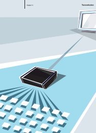
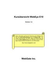
Figure 1 : Typical DVR installation.<br />
NOTE: This manual covers the 8- and 16-channel digital video recorders. The DVRs are identical except for the<br />
number of cameras and alarms that can be connected and the number of cameras that can be displayed.<br />
For simplicity, the illustrations and descriptions in this manual refer to the 16-camera model.
Chapter 2 — Installation<br />
Package Contents<br />
The package contains the following:<br />
<strong>Digital</strong> <strong>Video</strong> <strong>Recorder</strong><br />
Power Cord<br />
User’s Manual (This Document)<br />
RAS Software CD and User’s Manual<br />
Rack-mount Kit<br />
Assembly Screws for Adding Hard Disk Drives<br />
SATA Cables<br />
Audio Extension Cable<br />
Infrared Remote Control<br />
Required Installation Tools<br />
<strong>Digital</strong> <strong>Video</strong> <strong>Recorder</strong><br />
No special tools are required to install the DVR. Refer to the installation manuals for the other items that make up part<br />
of your system.<br />
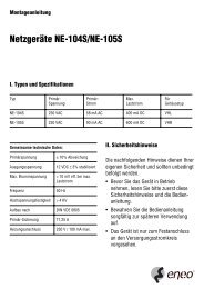
Figure 2 : 16-<strong>Channel</strong> DVR rear panel.<br />
<strong>Video</strong> Input <strong>Video</strong> Loop Through Factory Reset Switch<br />
HD/SD Out Selector Network Port iSCSI Port<br />
eSATA Port RS232C Port RS485 Port<br />
Alarm Input/Output Audio In/Out <strong>Video</strong> Out<br />
Power Cord Connector<br />
Your DVR can be used with either NTSC or PAL equipment.<br />
NOTE: You cannot mix NTSC and PAL equipment. For example you cannot use a PAL camera and an NTSC<br />
monitor.<br />
<strong>Video</strong> Input<br />
Connect the coaxial cables from the video sources to the BNC <strong>Video</strong> In connectors.<br />
3
4<br />
User’s Manual<br />
<strong>Video</strong> Loop Through<br />
If you would like to connect your video source to another device, you can use the Loop BNC connectors.<br />
NOTE: The Loop BNC connectors are auto terminated. Do NOT connect a cable to the Loop BNC unless it is<br />
connected to a terminated device because it will cause poor quality video.<br />
Factory Reset Switch<br />
The DVR has a Factory Reset switch to the right of the HD/SD Out selector on the rear panel. This<br />
switch will only be used on the rare occasions that you want to return all the settings to the original<br />
factory settings.<br />
CAUTION: When using the Factory Reset, you will lose any settings you have saved.<br />
To reset the unit, you will need a straightened paperclip:<br />
1. Turn the DVR off.<br />
2. Turn it on again.<br />
3. While the DVR is initializing, the front panel LEDs will blink. When the front panel LEDs blink, poke the<br />
straightened paperclip into the unlabeled hole to the right of the HD/SD Out selector.<br />
4. Hold the switch until all the LEDs on the front panel are lit.<br />
NOTE: When the DVR successfully resets to factory defaults all the LEDs on the front panel flash five times.<br />
5. Release the reset switch. All of the DVR’s settings are now at the original settings it had when it left the factory.<br />
HD/SD Out Selector<br />
Network Port<br />
A HD/SD Out selector is provided to select the monitor display mode between HD (High Definition) and<br />
SD (Standard Definition). Setting the selector to the HD OUT position sends HD video to the connected<br />
HDMI and VGA monitors, and setting to the SD OUT position sends SD video to the connected composite<br />
BNC monitor.<br />
The DVR can be networked using the 10Mb/1Gb Ethernet connector. Connect a Cat5 cable with an RJ-45<br />
jack to the DVR connector. The DVR can be networked with a computer for remote monitoring, searching,<br />
configuration and software upgrades. See Chapter 3 ─ Configuration for configuring the Ethernet<br />
connections.<br />
CAUTION: The network connector is not designed to be connected directly with cable or wire<br />
intended for outdoor use.<br />
iSCSI Port<br />
An iSCSI port is provided to connect external storage devices for recording video. Connect the external<br />
iSCSI hard disk drive (RAID) cable to the RJ-45 Ethernet port.<br />
NOTE: Up to eight iSCSI volumes (or nodes) can be connected to the DVR.<br />
CAUTION: Do NOT connect or disconnect iSCSI devices while the DVR power is on. The DVR must<br />
be powered down to connect or disconnect iSCSI devices. Power up iSCSI devices so<br />
they are ready for operation before powering up the DVR. Power down iSCSI devices<br />
after powering down the DVR and then disconnect iSCSI devices.
<strong>Digital</strong> <strong>Video</strong> <strong>Recorder</strong><br />
CAUTION: If the iSCSI device is shut down while the device is operating, the DVR system might not<br />
operate normally.<br />
eSATA Port<br />
An eSATA port is provided to connect external storage devices for recording or archiving video. Connect<br />
the external eSATA hard disk drive (RAID) cable to the eSATA port.<br />
CAUTION: Do NOT connect or disconnect eSATA devices while the DVR power is on. The DVR must<br />
be powered down to connect or disconnect eSATA devices. Power up eSATA devices<br />
so they are ready for operation before powering up the DVR. Power down eSATA devices<br />
after powering down the DVR and then disconnect eSATA devices.<br />
CAUTION: If the eSATA device is shut down while the device is operating, the DVR system might<br />
not operate normally.<br />
RS232C Port<br />
RS485 Port<br />
The DVR can be controlled remotely by an external device or control system, such as a control keyboard,<br />
using RS485 half-duplex serial communications signals. The RS485 connector can also be used to control<br />
PTZ (pan, tilt, zoom) cameras. Connect RX+/TX+ and RX-/TX- of the control system to the + and –<br />
(respectively) of the DVR. See Chapter 3 ─ Configuration and the PTZ camera or remote controller<br />
manufacture’s manual for configuring the RS485 connection.<br />
Alarm Input/Output<br />
An RS232 port is provided to connect a remote control keyboard.<br />
NOTE: To make connections on the Alarm Connector Strip, press and hold the button and insert the wire in the<br />
hole below the button. After releasing the button, tug gently on the wire to make certain it is connected.<br />
To disconnect a wire, press and hold the button above the wire and pull out the wire.<br />
AI 1 to 16 (Alarm-In): You can use external devices to signal the DVR to react to events. Mechanical or electrical<br />
switches can be wired to the AI (Alarm-In) and GND (Ground) connectors. The threshold voltage of electrical switches<br />
for NC (Normally Closed) is above 2.4V and for NO (Normally Open) is below 0.3V, and should be stable at least 0.5<br />
seconds to be detected. The voltage range of alarm input is from 0V to 5V. See Chapter 3 ─ Configuration for configuring<br />
alarm input.<br />
GND (Ground): Connect the ground side of the Alarm input and/or alarm output to the GND connector.<br />
NOTE: All the connectors marked GND are common.<br />
NC/NO (Relay Alarm Outputs): The DVR can activate external devices such as buzzers or lights. Connect the device<br />
to the C (Common) and NC (Normally Closed) or C and NO (Normally Open) connectors. NC/NO is a relay output<br />
which sinks 2A@125VAC and 1A@30VDC. See Chapter 3 ─ Configuration for configuring alarm output.<br />
ARI (Alarm Reset In): An external signal to the Alarm Reset In can be used to reset both the Alarm Out signal and<br />
the DVR’s internal buzzer. Mechanical or electrical switches can be wired to the ARI (Alarm Reset In) and GND (Ground)<br />
connectors. The threshold voltage is below 0.3V and should be stable at least 0.5 seconds to be detected. Connect the<br />
wires to the ARI and GND connectors.<br />
5
6<br />
User’s Manual<br />
Audio In/Out<br />
NOTE: It is the user’s responsibility to determine if local laws and regulations permit recording audio.<br />
<strong>Video</strong> Out<br />
The DVR does not have amplified audio output, so you will need a speaker with an amplifier. The DVR<br />
does not have a pre-amplifier for audio input, so the audio input should be from an amplified source, not<br />
directly from a microphone.<br />
NOTE: When using HDMI monitors, change the monitor display mode to HD mode by setting the HD/SD Out<br />
selector on the rear panel to the HD OUT position. HDMI video out will only enable in the HD display mode.<br />
VGA video out on the primary monitor will disable in the SD display mode.<br />
Composite (BNC) video out on the primary monitor will disable in the HD display mode.<br />
Monitor Connection Examples:<br />
< HD Display Mode ><br />
Your DVR can record audio from up to 16 sources. Connect the audio<br />
sources to Audio In 1 to Audio In 16 as needed using RCA jacks. Connect<br />
Audio Out to your amplifier. Use the provided audio extension cable to<br />
connect the audio sources to Audio In 5 to 16.<br />
A HDMI (High-Definition Multimedia Interface) connector is provided so that you can use a HDMI<br />
monitor as your primary monitor. Use the cable supplied with your monitor to connect it to the DVR.<br />
A VGA connector is provided so that you can use a standard, multi-sync computer monitor as your<br />
primary or secondary monitor. Use the cable supplied with your monitor to connect it to the DVR.<br />
Connect the primary or secondary monitor to the <strong>Video</strong> Out connector.<br />
Connect the spot monitor to the SPOT connector as needed.<br />
< SD Display Mode ><br />
NOTE: Connect the monitor before the DVR boots so that video can be displayed on the monitor with the resolution<br />
you have set during system setup.
Power Cord Connector<br />
Connect the AC power cord to the DVR and then to a wall outlet.<br />
<strong>Digital</strong> <strong>Video</strong> <strong>Recorder</strong><br />
WARNING: ROUTE POWER CORDS SO THAT THEY ARE NOT A TRIPPING HAZARD. MAKE<br />
CERTAIN THE POWER CORD WILL NOT BE PINCHED OR ABRADED BY FURNITURE.<br />
DO NOT INSTALL POWER CORDS UNDER RUGS OR CARPET.<br />
THE POWER CORD HAS A GROUNDING PIN. IF YOUR POWER OUTLET DOES NOT<br />
HAVE A GROUNDING PIN RECEPTACLE, DO NOT MODIFY THE PLUG. DO NOT<br />
OVERLOAD THE CIRCUIT BY PLUGGING TOO MANY DEVICES IN TO ONE CIRCUIT.<br />
Your DVR is now ready to operate. Refer to Chapter 3 ─ Configuration and Chapter 4 ─ Operation.<br />
7
8<br />
User’s Manual<br />
Chapter 3 — Configuration<br />
NOTE: Your DVR should be completely installed before proceeding. Refer to Chapter 2 — Installation.<br />
Front Panel Controls<br />
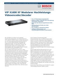
Figure 3 : 16-<strong>Channel</strong> DVR front panel.<br />
Camera Buttons Enter Button Arrow Buttons Menu Button<br />
Zoom Button PTZ Button Panic Button LED<br />
Display Button Monitor Button Bookmark Button Freeze Button<br />
Alarm Button Playback Buttons Jog Dial, Shuttle Ring USB Port<br />
The front panel looks and operates much like a VCR combined with a multiplexer. Many of the buttons have multiple<br />
functions. The buttons on the infrared remote control, while laid out differently, perform the same functions as those<br />
on the front panel. The following describes each button and control. Take a few minutes to review the descriptions.<br />
You will use these to initially set up your DVR and for daily operations.<br />
NOTE: The infrared sensor on the DVR is just to the left of LEDs. Make certain that nothing blocks the sensor,<br />
or the remote control will not function properly.<br />
You can also use a USB mouse (not supplied) to navigate through the screens and menus much like you<br />
would on a computer.
Figure 4 : Infrared remote control.<br />
NOTE: For simplicity, the button descriptions in this manual refer to the front panel buttons.<br />
Camera Buttons (1 to 16)<br />
<strong>Digital</strong> <strong>Video</strong> <strong>Recorder</strong><br />
Pressing the individual camera buttons will cause the selected camera to display full screen. Buttons 1 to 9 are also<br />
used to enter passwords.<br />
Enter Button<br />
The (Enter) button selects a highlighted item or completes an entry that you have made during system setup.<br />
Arrow Buttons<br />
These buttons are used to navigate through menus and GUI. You can also use them to change numbers by highlighting<br />
a number in the menu and using the Up and Down arrow buttons to increase or decrease the number’s value.<br />
These buttons are also used to control Pan and Tilt when in the PTZ mode.<br />
Menu Button<br />
Pressing the MENU button enters the Setup screen. You will need to enter the authorized user and password to access<br />
Setup. Pressing the button also closes the current menu or setup dialog box. In the Playback mode, pressing the button<br />
displays the Search menu. In the Search mode clip-copying can be done instantly by pressing and holding the button<br />
for three or more seconds.<br />
9
10<br />
User’s Manual<br />
ZOOM Button<br />
Pressing the ZOOM button zooms the current image on the screen. A PIP with a rectangle temporarily displays showing<br />
what area of the screen has been enlarged. You can use the arrow buttons to move the rectangle to another area.<br />
NOTE: Entering the zoom mode will NOT be supported while in the SD display mode.<br />
PTZ Button<br />
Pressing the PTZ button enters the PTZ (Pan/Tilt/Zoom) mode which allows you to control properly configured cameras.<br />
Panic Button<br />
Pressing the PANIC button starts panic recoding of all camera channels, and displays on the screen. Pressing the button<br />
again will stop panic recording.<br />
LED<br />
Power LED: The Power LED is lit when the unit is On.<br />
Network LED: The Network LED is lit when the unit is connected to a network via Ethernet.<br />
iSCSI LED: The iSCSI LED is lit when the iSCSI device is connected to the DVR.<br />
HDD LED: The HDD LED flickers when the DVR is recording or searching video on the hard disk drive.<br />
Display Button<br />
Pressing the DISPLAY button toggles between different display formats. The available formats are: 2x2, 3x2, 3x3, 4x3<br />
or 4x4 (2x2 or 4x4 on a Spot Monitor).<br />
Monitor Button<br />
Pressing the MONITOR button toggles the monitor selection between Primary (MONITOR 1 on the remote control),<br />
Secondary (MONITOR 2) and Spot (MONITOR 3). You can select the screen format and sequence monitoring of the<br />
selected monitor.<br />
Bookmark Button<br />
When in the playback mode, pressing the BOOKMARK button adds the current playback point to the bookmark list or<br />
moves to the registered bookmark point.<br />
Freeze Button<br />
Pressing the FREEZE button freezes the current live screen.<br />
Alarm Button<br />
The ALARM button has two functions. First, it will reset the DVR’s outputs including the internal buzzer during an<br />
alarm. Second, it will display the event log when you are in the live monitoring mode unless there is an active alarm.<br />
Playback Buttons<br />
Backward: When in the pause mode, pressing the button moves to the next image. The button is also used<br />
to Zoom Out while in the PTZ mode.
<strong>Digital</strong> <strong>Video</strong> <strong>Recorder</strong><br />
Forward: When in the pause mode, pressing the button moves to the previous image. The button is also used<br />
to Zoom In while in the PTZ mode.<br />
Rewind: Pressing the button plays video backward at high speed. Pressing the button again toggles the playback<br />
speed from , and . The button is also used for Near Focus in the PTZ mode.<br />
Play/Pause: Pressing the button plays back video at regular speed. The screen displays when the DVR is<br />
in the Pause mode and the screen displays when the DVR is playing back video. The button is also used for Far<br />
Focus in the PTZ mode.<br />
Fast Forward: Pressing the button plays video forward at high speed. Pressing the button again toggles the<br />
playback speed from , and . The button is also used to load a Preset View in the PTZ mode.<br />
Search/Stop: Pressing the button while in the Live Monitoring mode enters the Search mode. Pressing the<br />
button while in the Search mode returns the DVR to the Live Monitoring mode. The button is also used to save<br />
Presets while in the PTZ mode.<br />
Jog Dial, Shuttle Ring<br />
Jog Dial: When in the playback mode, you can play video forward image-by-image by turning the Jog Dial clockwise<br />
and backward image-by-image by turning the Jog Dial counterclockwise. When in the Setup mode, you can change<br />
number values by highlighting the item in the menu and turning Jog Dial clockwise or counterclockwise to increase<br />
or decrease the number.<br />
Shuttle Ring: The Shuttle Ring only functions in the Playback mode. The Shuttle Ring is spring loaded and returns<br />
to the center position when released. Turning the ring clockwise plays video forward. Turning the ring counterclockwise<br />
plays video backward. Playback speed varies with the amount the ring is turned. The playback speeds are , ,<br />
, x0.5, , , and . When you release the ring, it snaps back to the center position and the video<br />
pauses.<br />
USB Port<br />
Two USB ports on the front panel are provided to connect external hard disk or flash drives for video clip copying or<br />
system upgrades. Position external drives close enough to the DVR so that you can make the cable connections, usually<br />
less than 6 feet. Use the USB cable provided with the hard disk drive to connect it to the DVR.<br />
A USB mouse (not supplied) can be connected to one of the ports. You can use the mouse to navigate through the<br />
screens and menus much like you would on a computer.<br />
A PostScript USB printer (not supplied) can be connected to one of the ports. You can print selected images resulting<br />
from a search. Refer to Chapter 4 — Operation, Searching <strong>Video</strong>.<br />
A USB to Serial converter can be connected to the USB port. Multiple text-in devices can be used with a USB to Serial<br />
converter.<br />
ID Button on Remote Control<br />
If a DVR System ID is set to 0, the infrared remote control will control that DVR without any additional operations.<br />
(Refer to the System General setup screen in this chapter for further information on setting the System ID.) If the system<br />
ID is 1 to 16, you must to press the ID button on the remote control and then press the number button (1 to 16) in order<br />
to control that DVR. If the System ID of two or more DVRs is set to 0, those DVRs will react to the infrared remote<br />
control at the same time.<br />
Sequence Button on Remote Control<br />
Pressing SEQUENCE button displays live channels sequentially.<br />
Clip Copy Button on Remote Control<br />
Pressing the CLIP COPY button allows you to copy video clips.<br />
11
12<br />
User’s Manual<br />
Turning on the Power<br />
Connecting the power cord to the DVR turns on the unit. The unit takes approximately 60 seconds to initialize.<br />
Initial Unit Setup<br />
Before using your DVR for the first time, you will want to establish the initial settings. This includes items such as<br />
time and date, display language, camera, remote control, record mode, network and password. Your DVR can be set<br />
up using various screens and dialog boxes.<br />
Throughout the screens you will see . Highlighting the and pressing the button gives you the opportunity to<br />
reset that screen to its default settings. After you are finished with any setup screen, you can highlight Save and press<br />
the button to save the changes and exit the screen. If you do not wish to save the changes, highlight Cancel and<br />
press the button to exit the screen.<br />
Press the MENU button or move the mouse pointer to the top of the screen and then select (Login) in the Live<br />
Monitoring menu to enter the setup screens. The Login screen appears.<br />
Figure 5 : Login screen.<br />
Select a User and enter the password by pressing the appropriate<br />
combination of Camera number buttons and then the button. There<br />
is no default password when logging in the admin user for the first<br />
time.<br />
NOTE: To assure the secure management of the system, setting up a password is strongly recommended.<br />
If you cannot use the front panel buttons, click the button using the mouse to enter a password, and<br />
the virtual keyboard displays. See instructions below for using the virtual keyboard.<br />
To log the user out of the system, press the MENU button or move the mouse pointer to the top of the<br />
screen and then select (Logout) in the Live Monitoring menu. The Logout screen displays asking you<br />
to confirm whether or not you want to log out the current user.<br />
Figure 6 : Logout screen.
Setup Screen<br />
Figure 7 : Setup screen.<br />
<strong>Digital</strong> <strong>Video</strong> <strong>Recorder</strong><br />
System<br />
Record<br />
Network<br />
Event<br />
Device<br />
Display<br />
Status<br />
Camera<br />
Press the MENU button or move the mouse pointer to the top of the screen and then select (Setup) in the Live<br />
Monitoring menu to enter the setup screen.<br />
While setting up the DVR, there will be many opportunities to enter names and titles. When making these entries, a<br />
Virtual Keyboard will appear.<br />
Use the arrow keys to highlight the character you want in the name or title and press<br />
the button. That character appears in the title bar and the cursor moves to the next<br />
position. Pressing toggles between the upper and lower case keyboards,<br />
backspaces, and deletes entered characters.<br />
Special characters can be created using ^ and a capital letter; e.g., ^J for NL (New Line),<br />
^M for CR (Carriage Return). Special characters are commonly used by text input devices<br />
and will be useful when performing Text-In Searches.<br />
13
14<br />
User’s Manual<br />
System Setup<br />
General<br />
Highlight General and press the button, and the General screen appears.<br />
Figure 8 : System – General setup screen.<br />
In the General screen, you can name the site location, assign a System ID number, select the language the screens are<br />
displayed in, display software version number, upgrade the software, show the System Log, display recorded time data,<br />
and clear all data.<br />
Highlight the Site box and press the button. A virtual keyboard appears that you can use to enter a Site Name. Once<br />
you have entered your title, highlight OK and press the button.<br />
Highlight the box beside System ID and press the button. Change the number by highlighting it and using the Up<br />
and Down arrow buttons to increase and decrease the number from 0 to 99.<br />
NOTE: The System ID number is used to identify the unit when it is connected with other DVRs through the<br />
RS485 port. You cannot use the same ID number for two or more DVRs that are in the same RS485<br />
network. It is possible to have multiple DVRs with System ID 0 that are in the same area as long as they<br />
are not part of an RS485 network. If this is the case, all will be controlled at the same time when using<br />
the infrared remote control.<br />
Highlight the box beside Language and press button. A drop-down menu displays the available languages. Highlight<br />
the desired language and press the button.<br />
The box beside Version displays the software version of the DVR.<br />
To upgrade the software, connect a USB device containing the upgrade package file to the DVR. Highlight Upgrade…<br />
and press the button. The Upgrade screen appears. The screen displays the upgrade package file names that are<br />
available. The “.rui” indicates that the file is for software upgrades and “.ofi” indicates that the file is for optical drive<br />
firmware upgrades.<br />
Select the desired file and press the button. Highlighting the Install button and pressing the button will install<br />
the selected software package. Highlighting the Cancel button and pressing the button will close the window without<br />
upgrading the software. If the upgrade package file is not installed on the DVR properly, you will get an error message.<br />
The system restarts automatically after completing the upgrade.
CAUTION: The USB device must be FAT16 or FAT32 format.<br />
<strong>Digital</strong> <strong>Video</strong> <strong>Recorder</strong><br />
You can import saved DVR settings or export the current DVR settings. To import saved DVR settings, connect the<br />
USB device containing the setup file (.dat) to the DVR. Highlight Setup – Import… and press the button. Select<br />
the desired setup file and press the Import button to import the selected settings and change the DVR settings accordingly.<br />
Highlight Include Network Setup and press the button to toggle between On and Off. When set to Off, the network<br />
settings will not be changed.<br />
To export the current DVR settings, connect the USB device to the DVR. Highlight Setup – Export… and press the<br />
button. Highlight the box beside File name and press the button. A virtual keyboard allows you to enter the<br />
file name. Selecting Export will save the current settings in .dat file format on the USB device.<br />
NOTE: Even after changing the DVR settings by importing saved settings, the time-related settings (Date/Time,<br />
Time Zone and Daylight Saving Time) will NOT be changed.<br />
CAUTION: The USB device must be FAT16 or FAT32 format.<br />
Highlight Show System Log… and press the button to display the System Log.<br />
The System Log screen lists system activities (up to 5,000 from the latest) that have occurred along with the time and<br />
date. The icon will be displayed in the last column for system activities of the remote site. You can scroll through<br />
the log pages by using the Up and Down arrows, or you can go directly to a log page by entering the log page number<br />
in the box at the bottom left of the screen. Highlight Close and press the button to exit the screen.<br />
To export the system log information, connect the USB device to the DVR. Highlight Export… and press the button.<br />
Highlight the box beside File name and press the button. A virtual keyboard allows you to enter the file name.<br />
Selecting Export will save the log information in .txt file format on the USB device.<br />
15
16<br />
User’s Manual<br />
NOTE: When opening the saved .txt file, setting to the proper character encoding and using fixed width fonts<br />
will be required to read the file properly.<br />
Highlighting Clear All Data and pressing the button will clear all video data. You will be asked to verify that you<br />
wish to clear all data before the DVR erases the video data. Clear All Data will not clear the System Log.<br />
Highlighting System Shutdown and pressing the button. The Shutdown screen displays asking you to confirm<br />
whether or not you want to shut the system down.<br />
Date/Time<br />
After selecting Shutdown and pressing the button, a screen will appear telling you<br />
when it is safe to disconnect power.<br />
Highlight Date/Time and press the button, and the Date/Time setup screen appears.<br />
Figure 9 : System – Date/Time setup screen.<br />
Highlight the first box beside Date and press the button. The individual sections of the date will highlight. Use<br />
the Up and Down arrow buttons to change the number. Use the Left and Right arrow buttons to move between month,<br />
date and year. Once you have the correct date, press the button.<br />
Highlight the Format box beside Date and press the button. Select from the three available date formats and press<br />
the button to save your selected format.<br />
Highlight the first box beside Time and press the button. The individual sections of the time will highlight. Use<br />
the Up and Down arrow buttons to change the number. Use the Left and Right arrow buttons to move between hour,<br />
minutes and seconds. Once you have the correct time, press the button.<br />
Highlight the Format box beside Time and press the button. Select from the three available time formats and press<br />
the button to save your selected format.<br />
NOTE: The clock will not start running until you have highlighted Save and pressed the button.<br />
Highlight the box beside Time Zone and press the button. Select your time zone from the list and press the button.<br />
Highlight Use Daylight Saving Time and press the button. Pressing the button toggles between On and Off.<br />
Highlighting Time Sync.… and pressing the button displays the Time Sync. screen. You can set up time<br />
synchronization between the DVR and standard time servers that are available in most time zones and countries, or<br />
between the DVR and another DVR.
<strong>Digital</strong> <strong>Video</strong> <strong>Recorder</strong><br />
Highlight the box beside Automatic Sync. and press the<br />
button. This toggles between On and Off.<br />
Highlight the box beside Time Server and press the button.<br />
A virtual keyboard appears that you can use to enter the IP<br />
address or domain name of the time server.<br />
NOTE: You can use the domain name instead of IP address<br />
if you already set up the DNS Server when setting<br />
up the LAN.<br />
Highlight the box beside Interval and press the button. Set the time interval for synchronization from 30 minutes<br />
to 1 day at various time intervals.<br />
Last Sync-Time displays the last time the DVR was synchronized with the time server.<br />
Highlight Run as Server and press the button. Pressing the button toggles between On and Off. When it is<br />
On, the DVR you are setting up will run as a time server.<br />
Highlighting Holiday… and pressing the button displays the Holiday screen.<br />
Account<br />
You can set up holidays by highlighting + and pressing the button. The current<br />
date appears.<br />
Highlight the month and day and change them by using the Up and Down arrow<br />
buttons. Press the button to add the date. Dates can be deleted by highlighting<br />
the beside the date and pressing the button.<br />
NOTE: Holidays that do not fall on the same date each year should be updated<br />
once the current year’s holiday has passed.<br />
Highlight Account and press the button. The Account setup screen displays the authorized groups and users. You<br />
can add and delete groups and users. When adding a group, you can assign authority levels to the group.<br />
Figure 10 : System – Account setup screen.<br />
17
18<br />
User’s Manual<br />
The +/– column is used to collapse and expand user groups. If there is a + or – in this column, it indicates the item is<br />
a Group Name. If there is a – in front of the Group Name, it indicates that the group has been “expanded” and all of<br />
the User Names within that group are displayed below the Group Name. If there is a + in front of the Group Name, it<br />
indicates that the group has been “collapsed” and all of the User Names within that group are hidden. To collapse or<br />
expand a group, highlight the +/– column in front of the desired group and press the button.<br />
Highlighting a Group Name and pressing the button allows you to change the authority levels assigned to the group.<br />
CAUTION: Write down the new password and save it in a secure place. If the password is forgotten,<br />
the unit must be reset using the Factory Reset Button and all data settings will be lost.<br />
Highlighting a User Name and pressing the button allows you to add or change the password assigned to that user.<br />
You can also change the group to which the user is assigned.<br />
The column can be used to delete a User Name or an entire Group. If the is grayed out, that Group or User cannot<br />
be deleted. Highlight the and press the button. You will be asked to confirm that you want to delete the User or<br />
Group. To delete the User currently logged into the DVR on a local system or a PC running RAS, log the user out of<br />
the system first and then delete the user.<br />
To add a Group, highlight the + Group… box and press the button. A virtual keyboard appears allowing you to<br />
enter the Group name. You can use up to 15 characters including spaces in the group name. Enter the name and assign<br />
authority levels to the group.<br />
Highlighting the Authority box and pressing the button will toggle<br />
between all authority levels being turned On and Off. Highlighting<br />
the individual authority level boxes and pressing the button will<br />
toggle between that authority level being turned On and Off. The<br />
authority levels that can be turned On and Off are:<br />
Shutdown – The user can shut the system down on a local system.<br />
Upgrade – The user can upgrade the software on a local system or a PC<br />
running RAS.<br />
Color Control – The user can control brightness, contrast, hue and saturation<br />
for cameras on a local system or a PC running RAS.<br />
System Check – The user can view the remote system status or check<br />
the remote system status as a batch process on a PC running RAS.<br />
PTZ Control – The user can control the PTZ camera on a local system or a PC running RAS.<br />
Alarm-Out Control – The user can reset the DVR’s outputs including the internal buzzer during an alarm by pressing the ALARM<br />
button on a local system or alarm-out control button on a PC running RAS.<br />
Covert Camera View – The user can view video from cameras set as Covert while in the Live Monitoring or Search mode on<br />
a local system or a PC running RAS.<br />
Search – The user can access the Search mode on a local system or a PC running RAS.<br />
Clip-Copy – The user can copy video clips on a local system or a PC running RAS.<br />
Setup – The user without Setup authority cannot establish any system settings excluding system shutdown and logout on a local<br />
system or a PC running RAS.<br />
System Time Change – The user can change the system date and time on a local system or a PC running RAS.<br />
Data Clear – The user can clear all video data or format disks on a local system or a PC running RAS.<br />
PTZ Setup – The user can establish all PTZ settings on a local system or a PC running RAS.<br />
Alarm-Out Setup – The user can establish all Alarm-Out settings on a local system or a PC running RAS.<br />
Covert Camera Setup – The user can establish all Covert Camera settings on a local system or a PC running RAS.<br />
Record Setup – The user can establish all Record settings on a local system or a PC running RAS.<br />
To add a User, highlight the + User… box and press the button. A<br />
virtual keyboard appears allowing you to enter the User Name. Enter the<br />
name and assign the User to a Group and password. You can use camera<br />
buttons 1 to 9 on the front panel to assign the password. The password<br />
can be up to 8 digits. You will be asked to confirm the password.<br />
NOTE: In addition to using the front panel buttons or the infrared remote control, you can use the virtual keyboard<br />
to assign the password. To display the virtual keyboard click the button using the mouse (not supplied).
<strong>Digital</strong> <strong>Video</strong> <strong>Recorder</strong><br />
Highlighting the box beside Auto Login allows you to select a User to be automatically logged in when the DVR is<br />
powered up. It can also be set to never automatically login a user.<br />
Highlighting the box beside Auto Logout allows you to select from a list of times that the user will be automatically<br />
logged out. The options are: Never, 1 min., 3 min., 5 min., 10 min., 15 min., 20 min., 30 min. and 1 hr.<br />
Storage<br />
Highlight Storage and press the button. The Storage setup screen appears and displays information about the DVR’s<br />
storage devices.<br />
Figure 11 : System – Storage setup screen.<br />
The information in the Type column describes the storage device.<br />
The capacity of the storage device is displayed in the Capacity column.<br />
The Format column displays whether the device is used for recording (Record), archiving (Archive) or not (Not Using).<br />
Not formatted indicates the device is not formatted. indicates when the device has temporary space set aside so<br />
that video clips can be saved on a DVD RW.<br />
Highlight the box in the Format column for the desired storage device and<br />
press the button. You will be able to format the device for recording or<br />
archiving. When selecting Not Using from Use As and highlighting the<br />
Format button, the device will not be used for either recording or archiving.<br />
You can also set aside space to store temporary files for CD or DVD burning<br />
by selecting Partition – CD/DVD Burn.<br />
NOTE: The DVR does NOT support USB hard disk drives with a version lower than 2.0.<br />
NOTE: iSCSI devices cannot be formatted for archiving.<br />
The Information column displays whether the device is being used or not. Other indicates the device has been used<br />
for another DVR.<br />
Highlight the box in the Information column for the desired storage device and press the button. You will be able<br />
to check the time information about recorded data.<br />
19
20<br />
User’s Manual<br />
If you want to erase recorded data on the selected device,<br />
highlight Clear and press the button. You will be asked<br />
whether or not you want to delete the data.<br />
If you want to use a USB hard disk drive, highlight Use and<br />
press the button after connecting the device. Highlight<br />
Don’t Use and press the button if you want to stop using<br />
the device.<br />
CAUTION: Do NOT disconnect the USB cable or the power from the device while copying video clips.<br />
If the USB cable is disconnected while copying video clips, archived data might be lost.<br />
Highlight the boxes beside Mirror and press the button. The DVR can be set up to mirror Source disks to designated<br />
Dest. (destination) disks selected from internal hard disk drives. Refer to the Chapter 4 – Disk Mirroring for further<br />
information on setting up disk mirroring.<br />
Monitoring<br />
Highlight Monitoring and press the button, and the Monitoring setup screen appears.<br />
Figure 12 : System – Monitoring setup screen.<br />
The DVR can be configured to run self-diagnostics and report the results.<br />
Highlight the Settings box beside the desired event (System, Check Recording, Check Alarm-In, Disk Almost Full,<br />
Disk Bad, or Disk Temperature), and press the button.<br />
Highlight the Settings box beside System and press the button. You can select the interval that you want the DVR<br />
to run self-diagnostics on the system. You can select from 1 hr. to 30 days or Never.<br />
Highlight the Settings box beside Check Recording and press the button. The Check Recording screen appears.<br />
Highlighting Schedule On and pressing the button toggles On and<br />
Off. When set to On, you can select the day, time range and interval<br />
that you want the DVR to run self-diagnostics on the recorder. The<br />
Interval can be selectable from 1 min. to 7 days or Never. Highlight<br />
the + and press the button to add a schedule item. The box allows<br />
you to delete a check recording schedule.
<strong>Digital</strong> <strong>Video</strong> <strong>Recorder</strong><br />
Highlight the Settings box beside Check Alarm-In and press the button. You can select the interval that you want<br />
the DVR to run self-diagnostics on Alarm Inputs. You can select from 1 hr. to 30 days or Never.<br />
Highlight the Settings box beside Disk Almost Full, and press the button. Select the percentage level of disk usage<br />
at which you want the DVR to trigger an alert. Percentage levels range from 80% to 99%.<br />
Highlight the Settings box beside Disk Bad, and press the button. Select percentage level of bad disk sectors at<br />
which you want the DVR to trigger an alert. Percentage levels range from 10% to 90%.<br />
Highlight the Settings box beside Disk Temperature, and press the button. Select the temperature of hard disk<br />
drive at which you want the DVR to trigger an alert if the temperature exceeds the defined threshold. Refer to the hard<br />
disk drive manufacturer’s documentation for the correct temperature setting.<br />
The DVR can be set to react to system events. Highlight the Actions box beside the desired event and press the<br />
button. System events can be associated with an Alarm-Out connector, sound the DVR’s internal buzzer, and/or notify<br />
a number of different devices.<br />
NOTE: Alarm-Out action cannot be set to System and Panic Record events.<br />
Mail notify is the only option available for the System event.<br />
For the Notify action to work, the DVR should be registered in the RAS (Remote Administration System).<br />
Recording Setup<br />
General<br />
Highlight General and press the button, and the General setup screen appears.<br />
Figure 13 : Record – General setup screen.<br />
Highlighting Recycle and pressing the button toggles between On and Off. In the Recycle mode, the DVR records<br />
over the oldest video data once all available storage space has been used. When Recycle is turned off, the DVR stops<br />
recording once all available storage space has been used.<br />
Highlight the Event Record Dwell box and set the length of time you would like to record for the associated event.<br />
You can set the dwell from 5 seconds to 15 minutes. Refer to Event Actions screen in this chapter for information<br />
regarding event recording.<br />
Highlighting De-Interlace and pressing the button toggles between On and Off. When set to On, the DVR will<br />
turn the de-interlace filter on while recording video with Very High (D1) resolution.<br />
21
22<br />
User’s Manual<br />
NOTE: The video signal has a time difference of 1/60 second (1/50 second for PAL) between odd and even fields<br />
because it is composed of 60 interlaced fields per second (50 fields for PAL). When recording video with<br />
Very High (D1) resolution, video is made up of frame units combining two fields – one odd field and one<br />
even field. This can cause horizontal scan lines or flashes in areas with motion because of the time<br />
difference between the two fields. Turning on the de-interlace filter provides clearer video by eliminating<br />
these horizontal scan lines and flashes.<br />
The DVR can record up to 16 audio inputs. Highlighting Record Audio and pressing the button toggles between<br />
On and Off.<br />
Highlight the slide bar beside Auto Deletion, and use the Left and Right arrow buttons or Up and Down arrow buttons<br />
to adjust the length of time recorded data will be kept from 1 to 999 days. The DVR automatically deletes video recorded<br />
earlier than the user-defined period under three conditions: at midnight, whenever the system reboots or whenever the<br />
user changes the Auto Deletion settings. Selecting Never will disable the Auto Deletion function.<br />
Highlight the slide bar beside Limit Time-Lapse Recording, and use the Left and Right arrow buttons to adjust the<br />
length of the maximum storage time for time-lapse recording from 1 to 99 days. The Limit Time-Lapse Recording<br />
feature will function when the storage device has enough space to record video data longer than the preset period. When<br />
this feature is On, the DVR records over the oldest “time-lapse” video once all available storage has been used in the<br />
Recycle mode, so more event video can be saved. Selecting Never will disable the Limit Time-Lapse Recording function.<br />
NOTE: When the storage device does not have enough space to record video data longer than the preset Limit<br />
Time-Lapse Recording period, the DVR records over the oldest video data (time-lapse or event video)<br />
as it would in the Recycle mode even if this feature is turned On.<br />
The maximum storage time is only an estimate because the amount of space required to store video varies<br />
depending on many factors such as motion and image complexity.<br />
CAUTION: When more than one disk is installed in the unit, the DVR records video on the disks<br />
sequentially based on time. And these sequentially recorded videos have the advantage<br />
that you can search recorded video easily even though a disk is removed from the unit.<br />
However, video recorded in the same time range might be saved on different disks by<br />
channel and by the type of recording mode. Once the Limit Time-Lapse Recording is set<br />
to On, the DVR will maintain this recording limitation even after disabling the function.<br />
If you want the DVR to record video on the disks sequentially based on time again, you<br />
must format all disks that are currently used for recording.<br />
Highlighting Use Panic Recording and pressing the button toggles between On and Off.<br />
Highlight the Panic Recording – Duration box and set the duration of panic recording. Panic recording will stop<br />
automatically after the preset duration as long as the PANIC button is not pressed to stop the panic recording. You can<br />
set the dwell from 5 minutes to 1 hour. Select No Limit if you want to stop panic recording manually.<br />
Highlighting the Panic Recording – ips and pressing the button allows you to set the images per second for Panic<br />
recording. You can select from 1.00 to 30.00 ips (25.00 ips PAL).<br />
Highlighting the Panic Recording – Quality and pressing the button allows you to set the recorded image quality<br />
for Panic recording. You can select from: Very High, High, Standard and Basic.<br />
Highlighting the Panic Recording – Resolution and pressing the button allows you to set the recorded image<br />
resolution for Panic recording. You can select from: Very High (D1), High (Half D1) and Standard (CIF).
Schedule<br />
Highlight Schedule and press the button, and the Schedule setup screen appears.<br />
< Simple Mode ><br />
Figure 14 : Record – Schedule setup screen.<br />
< Advanced Mode ><br />
<strong>Digital</strong> <strong>Video</strong> <strong>Recorder</strong><br />
You can program the DVR to record only during certain times based on time, day of the week, and holidays. The smallest<br />
time segment you can use is 15 minutes.<br />
Highlighting Schedule On and pressing the button toggles between On and Off. In the Schedule On mode, the<br />
DVR records video based on the schedule established in the Schedule screen. When turning Schedule recording Off,<br />
you will be asked to confirm your decision, and displays at the top-left corner of each camera screen. Panic recording<br />
will function even when Schedule is turned off. displays during panic recording.<br />
Highlight the Schedule Mode box and press the button. You can select between Simple Mode and Advanced<br />
Mode. Selecting Advanced Mode allows you to set up individual recording schedule for each event.<br />
NOTE: Changing the schedule mode will reset all event and action statuses.<br />
Highlight the + and press the button to add a schedule item.<br />
Highlight the box under the Day heading and press the button to change the days that the scheduled recording will<br />
take place. Choose from: Sun, Mon, Tue, Wed, Thu, Fri, Sat, M~F, Hol and All.<br />
Highlight the box under the Range heading and press the button to change the time range that the scheduled recording<br />
will take place. The smallest time segment you can use is 15 minutes.<br />
Highlight the box under the Mode heading and press the button to change the recording mode that will be used.<br />
Choose from: No Record, Time, Event and Time & Event. (Simple Mode Only)<br />
When the DVR is in the No Record mode, it will not record during the preset day and time range as long as the PANIC<br />
button is not pressed. Use the No Record mode when you do NOT want the DVR to record during certain times.<br />
When the DVR is in the Time mode, the icon displays at the top-left corner of the screen. The DVR will record<br />
and displays the icon at the top-left corner of the screen during the scheduled times.<br />
When the DVR is in the Event mode, the red icon displays at the top-left corner of the screen. The DVR will record<br />
and displays the icon at the top-left corner of the screen when any event occurs. When the DVR is in the Pre-Event<br />
recoding mode, the yellow icon displays when there is no event, and the DVR is not recording. When the DVR is<br />
in the Pre-Event mode, the red and display when any event occurs and the DVR starts recoding.<br />
When the DVR is in the Time & Event mode, the DVR will follow the Time settings and the icon displays at the<br />
top-left corner of the screen. The DVR follows the Event settings and the icon displays.<br />
Highlight the box under the <strong>Channel</strong>s heading and press the button to select which cameras will be recorded. (Simple<br />
Mode Only)<br />
23
24<br />
User’s Manual<br />
Highlight the box under the Settings heading and press the button to define the recording settings.<br />
Figure 15 : Schedule – Settings (Advanced Mode) setup screen.<br />
You can set the ips, Quality and Resolution (ips, Quality, Resolution and Dwell for Advanced Mode setup) of the recording<br />
for any modes you set up in the Mode column. If you do not set the ips, Quality, Resolution and Dwell in the Settings<br />
column, the DVR will follow the default settings. See below for details.<br />
NOTE: Descriptions of the Record icons in the Type column are as follows:<br />
Time-lapse (Time) Alarm-In Motion<br />
<strong>Video</strong> Loss <strong>Video</strong> Blind Text-In<br />
<strong>Channel</strong>s that are not defined will use the setting values of the previous schedule item.<br />
NOTE: When multiple events are detected at the same time from a specific channel, the DVR will record event<br />
video with the high setting values if the ips, Quality, Resolution and Dwell values of events are different<br />
from each other. However, the ips will be reset to the supported maximum value when the ips, Quality,<br />
Resolution and Dwell are all set to the highest value. (Advanced Mode Only)<br />
Highlight the box under the heading and press the button to delete the recording settings. You will be asked to<br />
confirm that you want to delete the settings.<br />
Highlight Default… and press the button. The Default screen appears.<br />
Highlighting boxes under ips and pressing the button allows you to set the images per second for Time and Event<br />
recording. You can select from 1.00 to 30.00 ips (25.00 ips PAL).<br />
Highlighting boxes under Quality and pressing the button allows you to set the recorded image quality for Time<br />
and Event recording. You can select from: Very High, High, Standard and Basic.<br />
Highlighting boxes under Resolution and pressing the button allows you to set the recorded image resolution for<br />
Time and Event recording. You can select from: Very High (D1), High (Half D1) and Standard (CIF).<br />
Highlighting boxes under Dwell and pressing the button allows you to set the length of time you would like to record<br />
for the associated event. (Advanced Mode Only)
Pre-Event<br />
<strong>Digital</strong> <strong>Video</strong> <strong>Recorder</strong><br />
Highlight Pre-Event and press the button, and the Pre-Event setup screen appears. If you do not have Event set<br />
up in the Record Schedule, a message will display alerting you to this fact.<br />
Figure 16 : Record – Pre-Event setup screen.<br />
When the DVR is in the Event Record mode it is possible to have it record images before the event occurs. The Pre-Event<br />
screen allows you to define how to handle pre-event recording.<br />
You can turn individual cameras On or Off for pre-event recording. The image speed can be set from 1.00 to 30.00 ips<br />
(25.00 ips PAL), image quality can be selectable from Very High, High, Standard and Basic, and image resolution<br />
can be selectable from Very High (D1), High (Half D1) and Standard (CIF).<br />
You can set the amount of time to record prior to the event by adjusting the Dwell. You can set the Dwell from 5 seconds<br />
to 30 minutes. The longer the dwell set, the fewer maximum ips can be set.<br />
NOTE: When the DVR is in the Time or Time & Event mode, it ignores the pre-event settings and follows the time<br />
settings.<br />
Archive<br />
Highlight Archive and press the button, and the Archive setup screen appears.<br />
Figure 17 : Record – Archive setup screen.<br />
25
26<br />
User’s Manual<br />
Highlight Archive On and press the button to toggle between On and Off.<br />
NOTE: If you have not set up a storage device for archiving, a message appears notifying you of this.<br />
Select the Days and Time Range you want archived.<br />
You can accept the Archive Data Range by leaving the default checkmarks in the Last Archived and Continue boxes.<br />
If you wish to enter specific times and dates in From and To, toggle the checkmarks Off and then enter the time and<br />
date.<br />
Highlight Recycle and press the button to toggle between On and Off. When Recycle is On and the storage device<br />
is full, the newest archived video data will overwrite the oldest archived data. When Recycle is Off, the DVR will stop<br />
archiving video data until more space is made available.<br />
CAUTION: When the Recycle is On, changing the start date and time for archiving will delete all<br />
archived data after the hanged start date and time.<br />
Network Setup<br />
General<br />
Highlight General and press the button, and the General setup screen displays.<br />
Figure 18 : Network – General setup screen.<br />
Highlight the first box beside Remote Watch – bps/ips. Press the Up and Down arrow buttons to set the Transfer<br />
Speed from 50Kbps to 1Gbps.<br />
Highlight the second box beside Remote Watch – bps/ips. You can select the unit of measure for the transfer speed<br />
between: bps and ips. Press the button to set the transfer speed.<br />
Highlight the box beside Remote Watch – Quality and press the button. You can select the Quality from: Very<br />
High, High, Standard and Basic. Press the button to set the Quality.<br />
Highlight the box beside Remote Watch – Resolution and press the button. You can select the Resolution from:<br />
High (Half D1) and Standard (CIF). Press the button to set the Resolution.<br />
NOTE: The higher Quality and Resolution settings require higher Transfer Speed settings. The transfer speed<br />
you set is the maximum speed. Depending on the network environment, this speed may not be achieved.<br />
You can limit the network bandwidth settings so that system does not consume too much network bandwidth. Highlight<br />
the box beside Network Bandwidth Limit and press the Up and Down arrow buttons to set the desired maximum<br />
bandwidth from 50Kbps to 1Gbps.
<strong>Digital</strong> <strong>Video</strong> <strong>Recorder</strong><br />
NOTE: When limiting the network bandwidth, the remote watch image on the PC running RAS or WebGuard might<br />
not be displayed properly.<br />
The DVR supports two-way audio communication between a local system and a PC running RAS. Highlighting the<br />
box beside Remote Audio <strong>Channel</strong> and pressing the button allows you to select the audio channel that sends audio<br />
to the remote site. Selecting Select From RAS will send audio of the channel selected from RAS.<br />
NOTE: Depending on network conditions, audio might be interrupted or out of synchronization during<br />
transmission.<br />
Highlight Use WebGuard Service and press the button to toggle between On and Off. See Appendix – WebGuard<br />
for detailed descriptions of the WebGuard service.<br />
Highlight the box beside Port and press the button. Set the port number used when accessing WebGuard by using<br />
the Up and Down arrow buttons to increase or decrease the numbers.<br />
Highlight Use SSL for Transferring Data and press the button to toggle between On and Off. When it is On, the<br />
security of data except video and audio transmitted for remote monitoring or remote recording can be enhanced by<br />
using the SSL (Secure Sockets Layer) authentication. When using the SSL function, the DVR cannot be connected<br />
with a remote program or a network keyboard which does not support the SSL function.<br />
CAUTION: The remote connection will be disconnected temporarily after changing the SSL settings.<br />
NOTE: This product includes software developed by the OpenSSL Project for use in the OpenSSL Toolkit<br />
(http://www.openssl.org/).<br />
IP Address<br />
Highlight IP Address and press the button, and the IP Address setup screen displays.<br />
Figure 19 : Network – IP Address (Manual) setup screen.<br />
Highlight the box beside Type and press the button. You can select the type of network configuration from:<br />
Manual, DHCP and ADSL (with PPPoE). Select the desired type and press the button.<br />
Selecting Manual from the Type allows you to set up LAN parameters manually.<br />
Change the numbers by highlighting them and using the Up and Down arrow buttons to increase or decrease the<br />
number. The factory default LAN settings are:<br />
IP Address: 192.168.1.129<br />
Gateway: 192.168.1.254<br />
Subnet Mask: 255.255.255.0<br />
NOTE: You will need to get the appropriate IP Address, Gateway and Subnet Mask from your network<br />
administrator.<br />
27
28<br />
User’s Manual<br />
Highlight the box beside DNS Server. Press the Up and Down arrow buttons to set the IP address of the DNS server.<br />
Highlight the Port Number Setup… box and press the button. The Port Number Setup screen appears.<br />
NOTE: You will need to get the appropriate Port Numbers for each RAS and WebGuard related program (Admin,<br />
Callback, Watch, Search and Audio) from your network administrator.<br />
NOTE: The system restarts automatically after changing the port settings.<br />
Change the numbers by highlighting them and using the Up and Down<br />
arrow buttons to increase or decrease the number. The factory default<br />
Port settings are:<br />
Remote Admin: 8200<br />
Remote Callback: 8201<br />
Remote Watch: 8016<br />
Remote Search: 10019<br />
Remote Audio: 8116<br />
Do NOT use the same port number for two different programs, otherwise, the DVR cannot be connected<br />
with the PC running RAS or WebGuard.<br />
CAUTION: When changing the port settings, you must change the port settings on the PC running<br />
RAS as well. Refer to the RAS manual for details.<br />
Selecting DHCP from the Type and highlighting Save button reads the current IP address of the DVR configured by<br />
DHCP (Dynamic Host Configuration Protocol) network.<br />
Selecting ADSL (with PPPoE) allows you to set up the ADSL network.<br />
Highlight the box beside ID and press the button. A virtual keyboard appears allowing you to enter the ID for ADSL<br />
connection.<br />
Highlight the box beside Password and press the button. A virtual keyboard appears allowing you to enter the<br />
password for ADSL connection.<br />
NOTE: Entering the ID and Password and highlighting OK reads the current IP address of the DVR configured<br />
by the ADSL network.<br />
If the DVR is configured for DHCP or an ADSL network, the IP address of the DVR might change whenever<br />
the unit is turned on.
DVRNS<br />
Highlight DVRNS and press the button, and the DVRNS setup screen displays.<br />
Figure 20 : Network – DVRNS setup screen.<br />
Highlight Use DVR Name Service and press the button to toggle between On and Off.<br />
<strong>Digital</strong> <strong>Video</strong> <strong>Recorder</strong><br />
NOTE: The DVRNS (DVR Name Service) allows the DVR to use Dynamic IP addresses for remote connection.<br />
When this feature is On, you can access your DVR remotely using the DVR name instead of its IP address.<br />
For the DVRNS feature, the DVR should be registered on the DVRNS server.<br />
Highlight the box beside DVRNS Server and press the button. A virtual keyboard appears allowing you to enter<br />
the IP address or domain name of the DVRNS server.<br />
NOTE: You will need to get the IP Address or domain name of the DVRNS Server from your network administrator.<br />
You can use the domain name instead of IP address if you already set up the DNS Server when setting<br />
up the LAN.<br />
Highlight the box beside Port and press the button. Set the port number of the DVRNS server using the Up and<br />
Down arrow buttons to increase or decrease the numbers.<br />
Highlight Use NAT and press the button to toggle between On and Off.<br />
NOTE: When using the NAT (Network Address Translation) device, refer to the NAT manufacturer’s instructions<br />
for the proper network settings.<br />
Highlight the box beside DVR Name and press the button. A virtual keyboard appears allowing you to enter the<br />
DVR name to be registered on the DVRNS server.<br />
Highlight the Check box and press the button to check whether or not the name you entered can be used.<br />
NOTE: The DVR name you entered should be checked by selecting Check, otherwise the DVRNS changes will<br />
not be saved.<br />
When entering no name or a name already registered on the DVRNS server, an error message displays.<br />
Highlighting Save and pressing the button registers the DVR on the DVRNS server. Proper DVRNS settings will<br />
display the help desk information of the DVRNS server in the box beside Help Desk.<br />
29
30<br />
User’s Manual<br />
RTSP<br />
Highlight RTSP and press the button. The RTSP setup screen displays.<br />
Figure 21 : Network – RTSP setup screen.<br />
Highlight Enable RTSP (Real-Time Streaming Protocol) and press the button to toggle between On and Off. You<br />
will be able to change the settings if Enable RTSP is enabled.<br />
Highlight the box beside RTSP Port and press the button. Set the port number of the RTSP server obtained from<br />
your system administrator.<br />
Highlight the box beside RTP Start Port and press the button. Set the start port number of the RTP server obtained<br />
from your system administrator.<br />
Highlight the box beside RTP End Port and press the button. Set the end port number of the RTP server obtained<br />
from your system administrator.<br />
Highlight Use Mobile and press the button to toggle between On and Off. When set to on, you can access a remote<br />
DVR using a Blackberry or other mobile devices.<br />
NOTE: Selecting Use Mobile sets the WebGuard service to be enabled automatically regardless of your WebGuard<br />
settings.<br />
You can access a remote DVR and monitor live video images using media players, such as VLC Player,<br />
supporting RTSP service. Start the media player on your local PC and enter “rtsp://ID:Password@IP<br />
address:RTSP port number/track ID=‘channel number’”, or start Internet Explorer on your Blackberry<br />
or other mobile devices and enter “http://IP address:Webguard port number/”.<br />
RTSP service might not be supported, depending on the type of media player.
Notification<br />
<strong>Digital</strong> <strong>Video</strong> <strong>Recorder</strong><br />
Highlight Notification and press the button. The Notification setup screen displays. The DVR can be set up to contact<br />
a computer running RAS (Remote Administration System) or to send an email when an event occurs.<br />
Figure 22 : Network – Notification setup screen.<br />
Highlight Callback Enable and press the button to toggle between On and Off. You will only be able to change<br />
the IP addresses if Callback is enabled.<br />
Highlight the IP Address box that you want to change and press the button. Use the arrow buttons to enter the IP<br />
address of the computer you want contacted during an event. You can enter up to five IP addresses.<br />
Highlight the box beside Retry and enter the number of times you would like the DVR to try contacting the<br />
computer. You can select from 1 to 10 retries.<br />
Highlight Mail Enable and press the button to toggle between On and Off. You will only be able to change the<br />
settings if Mail is enabled.<br />
Highlight the box beside SMTP Server and press the button. A virtual keyboard appears that you can use to enter<br />
the IP address or domain name of the SMTP server.<br />
NOTE: You will need to get the IP Address or domain name of the SMTP Server from your network administrator.<br />
You can use the domain name instead of IP address if you already set up the DNS Server when setting<br />
up the LAN.<br />
Highlight the box beside Port and press the button. Use the arrow buttons to enter the SMTP Server port number<br />
obtained from your system administrator. The default port number is 25.<br />
Highlight Use SSL/TLS and press the button to toggle between On and Off. When it is On, the DVR can send an<br />
email via an SMTP server requiring SSL (Secure Sockets Layer) authentication.<br />
Highlight the box beside Authentication and press the button. An<br />
Authentication screen appears. Highlight Use and press the button<br />
to toggle between On and Off. Highlight the box beside User/Password<br />
and press the button. A virtual keyboard appears allowing you to<br />
enter the user ID and password.<br />
NOTE: In addition to using the front panel buttons or the infrared remote control, you can use the virtual keyboard<br />
to assign the password. To display the virtual keyboard click the button using the mouse (not supplied).<br />
This product includes software developed by the OpenSSL Project for use in the OpenSSL Toolkit<br />
(http://www.openssl.org/).<br />
31
32<br />
User’s Manual<br />
Highlight the box beside Sender and enter the sender’s e-mail address. Use the virtual keyboard to enter the e-mail<br />
address.<br />
NOTE: The e-mail address must include the “@” character to be a valid address.<br />
Highlight the box beside Recipient and enter the recipient’s e-mail address. Use the virtual keyboard to enter the e-mail<br />
address.<br />
Highlight the Test box and press the button to test emailing with the current settings you made.<br />
iSCSI<br />
Highlight iSCSI and press the button. The iSCSI setup screen displays.<br />
Figure 23 : Network – iSCSI setup screen.<br />
Highlight Use iSCSI Name Service and press the button to toggle between On and Off.<br />
Highlight the DVR – Initiator Address box and press the button. Use the arrow buttons to enter the IP address of<br />
DVR.<br />
NOTE: You will need to get the IP address from your network administrator.<br />
Do NOT use the same IP address for the Initiator Address set here and IP address set during Network –<br />
IP Address setup, otherwise the iSCSI changes will not be saved.<br />
Highlight the DVR – Initiator Node Name box and press the button. A virtual keyboard appears allowing you to<br />
enter the DVR name to be registered on the iSCSI device.<br />
Highlight the iSCSI – Target Address box and press the button. Use the arrow buttons to enter the IP address of<br />
the iSCSI device that you are connecting to the DVR.<br />
Highlight the iSCSI – Target Port box and press the button. Use the arrow buttons to enter the port number of<br />
the iSCSI device that you are connecting to the DVR.
<strong>Digital</strong> <strong>Video</strong> <strong>Recorder</strong><br />
Highlight the iSCSI – Target Nodes box and press the button, and the Target Nodes screen appears.<br />
Highlighting Discover and pressing the button. Proper iSCSI settings will display the list of iSCSI hard disk drives<br />
currently connected to the DVR in the Target Node Name list, and selecting a specific device from the list displays<br />
its full name in the Full Node Name box. Selecting a desired device and selecting OK allows you to use the selected<br />
device for recording.<br />
Highlight the box beside iSCSI – CHAP Authentication and press the button. An Authentication screen appears.<br />
Highlight Use and press the button to toggle between On and Off.<br />
Highlight the box beside User/Password and press the button.<br />
A virtual keyboard appears allowing you to enter the user ID and<br />
password.<br />
NOTE: Setting up the Authentication will be required to access the iSCSI device that uses the CHAP Authentication<br />
function.<br />
The box beside Session displays the current connection status between the DVR and iSCSI device.<br />
NOTE: The system restarts automatically after changing the iSCSI settings.<br />
When using the iSCSI device, refer to the device manufacturer’s instructions for the proper settings.<br />
Recorded video and audio on the iSCSI device might not be played properly depending on the network<br />
conditions.<br />
CAUTION: The iSCSI device should be connected directly to the iSCSI connector on the rear panel<br />
of the DVR.<br />
33
34<br />
User’s Manual<br />
Event Setup<br />
Motion<br />
Highlight Motion and press the button, and the Motion setup screen appears.<br />
Figure 24 : Event – Motion setup screen.<br />
Your DVR has built-in video motion detection. <strong>Video</strong> motion detection can be turned On or Off for each camera.<br />
Highlighting the box under the Sensitivity heading and pressing the button<br />
allows you to adjust the DVR’s sensitivity to motion for Daytime and Nighttime<br />
independently. There are five settings with 1 being the least sensitive and 5<br />
being the most sensitive.<br />
You can define the area of the image where you want to detect motion; e.g., a doorway. Highlight the box under the<br />
Zone heading, and press the button. The Motion Detection Zone screen displays.<br />
The Motion Detection Zone screen is laid over the video for the selected<br />
camera. You can set up motion detection zones by selecting or clearing<br />
blocks.<br />
NOTE: You can set up motion zones one block at a time in groups of 8<br />
individual block groups. A block group is positioned within<br />
the image area using the Up and Down arrow buttons, and<br />
individual blocks within the block groups are selected or<br />
cleared using the camera buttons.<br />
Press the button to display the menu screen. The menu on the setup screen has the following functions:<br />
Select — Activates highlighted blocks to detect motion.<br />
Clear — Deactivates highlighted blocks so that they will not detect motion.<br />
Reverse — Activates inactive highlighted blocks and deactivates active highlighted blocks.<br />
Select All — Activates all blocks to detect motion.<br />
Clear All — Deactivates all blocks so that they will not detect motion.<br />
Reverse All — Activates inactive blocks and deactivates active blocks.<br />
Zone View — Displays any detected motion within the zone in red.<br />
OK — Accepts changes and closes Zone setup.<br />
Cancel — Exits Zone setup without saving changes.
NOTE: Displaying the detection zone is supported only in the HD display mode.<br />
<strong>Digital</strong> <strong>Video</strong> <strong>Recorder</strong><br />
You can adjust the minimum number of detection blocks that must be<br />
activated to trigger a motion alarm. Highlighting the box under the Min.<br />
Blocks heading and pressing the button allows you to adjust the minimum<br />
number of detection blocks for Daytime and Nighttime independently.<br />
Smaller numbers provide greater sensitivity because fewer detection blocks<br />
must be activated.<br />
Highlighting the box under the Actions and pressing the button. The DVR can be set to react to motion detection<br />
differently for each camera. Each camera can be associated with another camera, trigger an Alarm-Out connector,<br />
sound the DVR’s internal buzzer, notify a number of different devices, move PTZ cameras to preset positions, and/or<br />
display a camera on a SPOT monitor.<br />
You can control excessive event logging and remote notification of motions detected after the motion dwell time by<br />
adjusting the motion ignoring dwell intervals. Highlight the box beside Motion Ignoring Interval and press the<br />
button. A list of intervals ranging from 1 to 5 seconds or Never appears. The DVR will not log and notify motion events<br />
occurred during the preset interval range.<br />
NOTE: The record action for motion events will not be affected by the Motion Ignoring function.<br />
Highlighting Daytime Setup and pressing the button allows you to set up the Daytime range.<br />
Alarm-In<br />
Highlight the box beside Daytime and press the button. Use the<br />
Up and Down arrow buttons to set the Daytime range. The DVR will<br />
consider the remaining time range as the Nighttime.<br />
Highlight Alarm-In and press the button, and the Alarm-In setup screen appears.<br />
Figure 25 : Event – Alarm-In setup screen.<br />
The alarm terminal strip on the back of the DVR has inputs associated with each alarm. You can set up each input on<br />
the Alarm-In screen. You can turn each input On or Off by highlighting the alarm number and pressing the button.<br />
Each input can be given a title. Highlight the desired Title box and press the button. A virtual keyboard appears<br />
allowing you to enter a title name.<br />
Each input can be set as NO (normally open) or NC (normally closed).<br />
Highlighting the box under the Actions and pressing the button. You can set the actions the DVR will take whenever<br />
it senses an input on one of its alarm input connectors. Alarm input can be associated with cameras, trigger an Alarm-Out<br />
35
36<br />
User’s Manual<br />
connector, sound the DVR’s internal buzzer, notify a number of different devices, move PTZ cameras to preset positions,<br />
and/or display a camera on a SPOT monitor.<br />
<strong>Video</strong> Loss<br />
Highlight <strong>Video</strong> Loss and press the button, and the <strong>Video</strong> Loss setup screen appears.<br />
Figure 26 : Event – <strong>Video</strong> Loss setup screen.<br />
Highlighting the box under the Actions and pressing the button. The DVR can be set to react to video loss differently<br />
for each camera. Each camera can be associated with another camera, trigger an Alarm-Out connector, sound the DVR’s<br />
internal buzzer, notify a number of different devices, move PTZ cameras to preset positions, and/or display a camera<br />
on a SPOT monitor.<br />
The DVR checks to see if anything is obscuring the camera. Highlight the box beside Check Obscuration, and press<br />
the button. A list of sensitivity ranging from 1 to 10 or Never appears. The sensitivity can be set from Never to<br />
10 (extremely sensitive).<br />
<strong>Video</strong> Blind<br />
Highlight <strong>Video</strong> Blind and press the button, and the <strong>Video</strong> Blind setup screen appears. The DVR checks to see if<br />
anything is blinding a camera.<br />
Figure 27 : Event – <strong>Video</strong> Blind setup screen.
<strong>Digital</strong> <strong>Video</strong> <strong>Recorder</strong><br />
You can turn individual cameras On or Off for video blind detection by highlighting the camera number and pressing the<br />
button.<br />
Highlighting the box under the Sensitivity heading<br />
allows you to adjust the DVR’s sensitivity to video blind<br />
from 1 (least sensitive) to 10 (most sensitive).<br />
NOTE: <strong>Video</strong> blind might NOT be detected for a camera with a very noisy image especially when set for low<br />
sensitivity values.<br />
Highlighting the box under the Activation Time heading allows you to set the duration before the DVR will report a<br />
<strong>Video</strong> Blind. The DVR will not consider any blinded camera to be a <strong>Video</strong> Blind if the detected blindness is less than<br />
the Activation Time set on this screen.<br />
Highlighting the box under the Actions and pressing the button. The DVR can be set to react to video blind differently<br />
for each camera. Each camera can be associated with another camera, trigger an Alarm-Out connector, sound the DVR’s<br />
internal buzzer, notify a number of different devices, move PTZ cameras to preset positions, and/or display a camera<br />
on a SPOT monitor.<br />
Highlight Use Ignoring Time and press the button to toggle between On and Off. When set to On, the DVR will<br />
ignore video blind events occurred during the preset period. Highlighting Time Setup and press the button allows<br />
you to set up event ignoring time.<br />
Text-In<br />
Highlight Text-In and press the button, and the Text-In setup screen appears.<br />
Figure 28 : Event – Text-In setup screen.<br />
The DVR can be set to react to text input from devices such as ATMs (Automated Teller Machines) and POS (Point<br />
of Sale; i.e., cash registers). This screen allows you to configure the DVR for each text-in device.<br />
Highlight the box under the Setup heading, and press the button. Selecting the Setup heading changes all the<br />
parameters excluding Port settings of all the text input channels.<br />
NOTE: The system performance might be affected when a large quantity of text inputs are detected from several<br />
channels at the same time.<br />
37
38<br />
User’s Manual<br />
Figure 29 : Text-In Device screen.<br />
Highlight the box beside Port, and press the button. Select from None, RS232, RS485, USB-Serial (1~8) and LAN<br />
(1~4).<br />
NOTE: If you have set the Port as None, you will not be able to make any changes to the screen.<br />
When using the USB to serial text-in device, do NOT remove the USB cable from the port while the system<br />
is running.<br />
Highlight Setup…, and press the button. Use the ATM or POS manufacturer’s recommended settings when configuring<br />
the RS232, RS485, USB-Serial or LAN ports.<br />
Highlight the box beside Text-In Product, and press the button. Select your device from the list.<br />
NOTE: The following description is for a Generic Text Device. The screen changes for different types of text<br />
input devices, and there will be different parameter boxes for you to enter information.<br />
Highlight the box beside Transaction Start, and press the button. Use the virtual keyboard to enter the Transaction<br />
Start string. Refer to the device manufacturer’s documentation for the text string that the device first sends when a<br />
transaction starts.<br />
If you want the DVR to react to any character sent from the text input device, you will want to turn On Any Character.<br />
Highlight Any Character, and press the button to toggle between On and Off.<br />
NOTE: If Any Character is turned On, you will not be able to enter any text in the Transaction Start box.<br />
Highlight the box beside Transaction End, and press the button. Use the virtual keyboard to enter the Transaction<br />
End string. Refer to the device manufacturer’s documentation for the text string that the device sends when a transaction<br />
ends.<br />
Highlight the more line(s) box, and press the button. Select the number of additional lines of text that you want<br />
the DVR to record. You can choose from 0 to 10.<br />
Highlight the box beside Line Delimiter, and press the button. Use the virtual keyboard to enter the character(s)<br />
that the device uses to indicate the end of a line. Special characters can be created using ^ and a capital letter; e.g., ^J<br />
for NL (New Line), ^M for CR (Carriage Return). Refer to the device manufacturer’s documentation for Line Delimiter<br />
character(s).<br />
Highlight the box beside Ignore String, and press the button. Use the virtual keyboard to enter any strings of text<br />
that you want the DVR to ignore. Refer to the device manufacturer’s documentation for text strings that the device<br />
sends during transactions, so you will know which ones you do not want recorded.<br />
Highlight the Case Sensitive box, and press the button to toggle between On and Off. Refer to the device<br />
manufacturer’s documentation to determine if the text strings are Case Sensitive. If the device distinguishes between<br />
upper and lower case letters, make certain the Case Sensitive box is turned On.<br />
Highlight the box beside Time Out, and press the button. Set the length of time to wait for the new text string. The<br />
DVR will consider a transaction complete if no new text strings are entered between the last text input and the dwell<br />
time out. You can adjust the Time Out dwell from 5 seconds to 15 minutes.<br />
Highlighting the box under the Actions and pressing the button. The DVR can be set to react to text input. Text
<strong>Digital</strong> <strong>Video</strong> <strong>Recorder</strong><br />
input can be associated with cameras, trigger an Alarm-Out connector, sound the DVR’s internal buzzer, notify a number<br />
of different devices, move PTZ cameras to preset positions, and/or display a camera on a SPOT monitor.<br />
Device Setup<br />
Audio<br />
Highlight Audio and press the button, and the Audio setup screen appears.<br />
Figure 30 : Device – Audio setup screen.<br />
The DVR can record up to 16 audio inputs. Highlight the box beside the input and press the button. A list of cameras<br />
appears, and you can select which camera you want associated with that audio input.<br />
Highlight Enable Audio-Out and press the button. This toggles between enabling and disabling audio out.<br />
Alarm-Out<br />
Highlight Alarm-Out and press the button. The Alarm-Out screen allows you to change the settings and establish<br />
a schedule for each alarm output from the DVR.<br />
Figure 31 : Device – Alarm-Out setup screen.<br />
39
40<br />
User’s Manual<br />
Highlighting the box beside Dwell Time and pressing the button allows you to set the dwell time of the alarm output.<br />
Dwell times range from 5 seconds to 15 minutes.<br />
Each alarm output can be given its own title by highlighting Title… and pressing the button. A virtual keyboard<br />
appears allowing you to enter the title.<br />
You can add and edit alarm output schedules. Highlight the + and press the button to add a schedule. Highlighting<br />
the boxes under the Column heading and pressing the button allows you to edit the information in those boxes.<br />
Highlighting the boxes under the Day box and pressing the button allows you to select the days that the alarm schedule<br />
will be active. The choices are: Sun, Mon, Tue, Wed, Thu, Fri, Sat, M~F, Hol and All.<br />
Highlighting the boxes under the Range box and pressing the button allows you to set the time that the alarm schedule<br />
will be active in 15-minute increments from 00:00 to 24:00.<br />
Highlighting the boxes under the Mode box and pressing the button allows you to set how the alarm reacts during<br />
the scheduled time. When set to On, the Alarm-Out is active during the scheduled time. When set to Event, the<br />
Alarm-Out is only active when there is an Event during the scheduled time.<br />
Highlighting the boxes under the <strong>Channel</strong>s box and pressing the button allows you to set which alarm outputs will<br />
be active. You can also select the DVR’s internal buzzer.<br />
The box allows you to delete an alarm output schedule. You will be asked to confirm whether or not you really wish<br />
to delete the schedule.<br />
Remote Control<br />
Highlight Remote Control and press the button. The Remote Control setup screen allows you to select a port and<br />
make correct settings for a remote keyboard.<br />
Figure 32 : Device – Remote Control setup screen.<br />
Highlight the box beside Port and select from None, RS232 and RS485. If the RS232 port and RS485 port are in use<br />
for PTZ control, networking or text input, the remote keyboard cannot be configured.<br />
Highlight Setup… and select the correct Baud Rate, Parity, Data Bits and Stop Bits for the device you are connecting<br />
to the DVR.<br />
Highlight the box beside Remote Control Product and select the device from the list.
Display Setup<br />
OSD<br />
<strong>Digital</strong> <strong>Video</strong> <strong>Recorder</strong><br />
Highlight OSD and press the button. The OSD screen allows you to select what information will be displayed on<br />
the monitor.<br />
Figure 33 : Display – OSD setup screen.<br />
Highlighting an item and pressing the button toggles that item On and Off. When an item is On, there is a checkmark<br />
in the box beside it. The following items can be turned On or Off:<br />
Remote Control – The icon displays when the DVR can be controlled by the infrared remote control.<br />
Zoom – The icon displays on the enlarged video.<br />
Network – The icon displays when the unit is connected to a network via Ethernet. The icon displays on each camera<br />
when audio communication is available between the DVR and a PC running RAS via Ethernet.<br />
Freeze & Sequence – The icon displays while in the Freeze mode, and the displays while in the Sequence mode.<br />
Screen Group – The number of screen group displays when the DVR is not in the 4x4 display mode of the 16-channel DVR,<br />
and 3x3 mode of the 8-channel DVR.<br />
Free Space – The icon displays when the DVR is in the Recycle mode, and the percentage of available storage space displays<br />
when the DVR is not in the Recycle mode.<br />
Archive – The icon displays when the DVR is archiving recorded data.<br />
Mirror – The icon displays when the DVR is disk mirroring.<br />
Date/Time – The current date and time information displays.<br />
User Name – The name of the current user logged in displays.<br />
Background Panel – The background panel at the bottom of the screen displays in black.<br />
Camera No. – The camera number displays at the top-left corner of each camera screen.<br />
Camera Title – The camera title displays at the top-left corner of each camera screen.<br />
Record – The record related icons display on each camera screen.<br />
Audio – The icon displays on each camera screen for which the DVR can play live audio.<br />
PTZ – The icon displays on each PTZ camera screen.<br />
Text-In – The text input strings display on the screen. You can adjust the Display Dwell time (sec.) for the text input strings displayed<br />
on the screen.<br />
You can adjust the transparency of the setup screens by highlighting Transparency and using the Left and Right arrow<br />
buttons.<br />
Highlighting OSD Margin… and pressing the button displays how OSD text will be<br />
displayed on the monitor. You can adjust the horizontal and vertical margins so that text<br />
and icons will not be hidden beyond the edges of the monitor.<br />
NOTE: Adjusting the OSD margin is supported only in the SD display mode.<br />
41
42<br />
User’s Manual<br />
Primary Monitor<br />
Highlight Primary Monitor and press the button, and the Primary Monitor setup screen appears.<br />
Figure 34 : Display – Primary Monitor setup screen.<br />
Highlight the box beside Mode and press the button. You can select between Full Sequence and Cameo Sequence.<br />
Pressing the SEQUENCE button on the remote control or selecting (Sequence) in the Live Monitoring menu causes<br />
the DVR to sequence cameras, and the DVR can sequence cameras in two modes: “Full” and “Cameo”. In the Full<br />
mode, the DVR sequences through the cameras and displays them full screen. In the Cameo mode, the bottom right<br />
window in a multi-screen format sequences through the cameras.<br />
NOTE: Any cameras that are Off, have lost video or are set to Covert (unless the user has authority to view covert<br />
cameras) will be excluded from the Cameo sequence.<br />
You can define the screen layout in a variety of formats and set the DVR to sequence through the different screen layouts<br />
(pages) so that all the cameras will be displayed. You can also set up the DVR to display one camera or a group of<br />
cameras all the time while cycling through the remaining cameras in a “cameo” window. This can be done with one<br />
camera displayed full screen while displaying the cameo window as a PIP (picture in picture), or displaying the cameras<br />
in a grid pattern with the bottom right window as the cameo.<br />
NOTE: Sequence cannot be used in the 4x4 display mode of the 16-channel, and 3x3 mode of the 8-channel DVR.<br />
You can adjust the display dwell time by highlighting the box beside Interval and pressing the button. You can<br />
select dwell intervals ranging from 1 second to 1 minute.<br />
Highlight Event Monitoring On and press the button. Pressing the button toggles between On and Off. When<br />
it is On, the DVR will display the camera associated with the event when an event occurs.<br />
Highlight the box beside Resolution and press the button. You can select from 1280x1024, 1440x900, 1600x900,<br />
1680x1050 and 1920x1080 for NTSC video, and 1280x1024, 1440x900, 1600x900, 1680x1050 and 1920x1080 (@<br />
60Hz or 50Hz) for PAL video.<br />
Highlight the box beside Hide Unsupported Resolution and press the button. Pressing the button toggles between<br />
On and Off. When it is On, the unsupported resolution on the connected monitor will not be shown.<br />
NOTE: When selecting unsupported resolution, video might NOT be displayed on the monitor screen. In this<br />
case, pressing the DIPSLAY button for more than five seconds will change to the different frequency (Hz)<br />
resolution or restart the system and display video with the maximum resolution supported on the monitor.<br />
Highlight Fit To Screen and press the button. Pressing the button toggles between On and Off. When it is On,<br />
the DVR will resize video to fit to the primary monitor screen.<br />
Highlight the box beside Apply Monitor Information and press the button. Pressing the button toggles between<br />
On and Off. When it is On, the DVR will provide clearer display by applying the monitor information.
<strong>Digital</strong> <strong>Video</strong> <strong>Recorder</strong><br />
Highlight the box beside HDMI Mode and press the button. Pressing the button toggles between On and Off.<br />
When it is On, the DVR will optimize the HDMI video out.<br />
NOTE: The system restarts automatically after changing the resolution settings. If the system restarts when<br />
the monitor is not connected, the resolution will be set to 1280x1024@60Hz as default without saving<br />
your changes.<br />
When the individual primary monitors are connected to the HDMI and VGA connectors for simultaneous<br />
operation, it is recommended to use monitors supported with the same resolution. If monitors unsupported<br />
with the same resolution are connected, video might not be displayed on either of the two monitors or<br />
displayed with the minimum resolution supported on the monitor.<br />
Secondary Monitor<br />
Highlight Secondary Monitor and press the button, and the Secondary Monitor setup screen appears.<br />
Figure 35 : Display – Secondary Monitor setup screen.<br />
Highlight the box beside Mode and press the button. You can select between Full Sequence and Cameo Sequence.<br />
Pressing the SEQUENCE button on the remote control or selecting (Sequence) in the Live Monitoring menu causes<br />
the DVR to sequence cameras, and the DVR can sequence cameras in two modes: “Full” and “Cameo”. In the Full<br />
mode, the DVR sequences through the cameras and displays them full screen. In the Cameo mode, the bottom right<br />
window in a multi-screen format sequences through the cameras.<br />
NOTE: Any cameras that are Off, have lost video or are set to Covert (unless the user has authority to view covert<br />
cameras) will be excluded from the Cameo sequence.<br />
You can define the screen layout in a variety of formats and set the DVR to sequence through the different screen layouts<br />
(pages) so that all the cameras will be displayed. You can also set up the DVR to display one camera or a group of<br />
cameras all the time while cycling through the remaining cameras in a “cameo” window. This can be done with one<br />
camera displayed full screen while displaying the cameo window as a PIP (picture in picture), or displaying the cameras<br />
in a grid pattern with the bottom right window as the cameo.<br />
NOTE: Sequence cannot be used in the 4x4 display mode of the 16-channel, and 3x3 mode of the 8-channel DVR.<br />
You can adjust the display dwell time by highlighting the box beside Interval and pressing the button. You can<br />
select dwell intervals ranging from 1 second to 1 minute.<br />
43
44<br />
User’s Manual<br />
Spot Monitor<br />
Highlight Spot Monitor and press the button, and the Spot Monitor setup screen appears.<br />
Figure 36 : Display – Spot Monitor setup screen.<br />
Highlight the box in the <strong>Channel</strong>s column and press the button.<br />
You can define which cameras display sequentially<br />
on the Spot Monitor when in the single-screen display<br />
format. Highlighting the box under the Camera and<br />
pressing the button toggles between On and Off.<br />
You can adjust the display dwell time by highlighting<br />
the box under the Dwell and pressing the button.<br />
You can select dwell intervals ranging from 1 to 20<br />
seconds.<br />
Pressing the SEQUENCE button on the remote control or selecting (Sequence) in the Live Monitoring menu causes<br />
the DVR to sequence cameras.<br />
NOTE: Sequence cannot be used in the 4x4 display mode of the 16-channel.
Status Setup<br />
Event<br />
Highlight Event and press the button, and the Event setup screen appears.<br />
Figure 37 : Status – Event setup screen.<br />
<strong>Digital</strong> <strong>Video</strong> <strong>Recorder</strong><br />
The Event Status screen displays the status of the DVR’s systems and inputs. Events will be highlighted, and related<br />
channels or events will flicker for five seconds when detected.<br />
Alarm-In, Motion, <strong>Video</strong> Loss, <strong>Video</strong> Blind and Text-In will be highlighted when each event is detected based on<br />
the settings you made in the Alarm-In, Motion, <strong>Video</strong> Loss, <strong>Video</strong> Blind and Text-In setup screen on the Event menu.<br />
Check Alarm-In and Check Recording will be highlighted when each event is detected based on the settings you<br />
made in the Monitoring setup screen on the System menu.<br />
Panic Record will be highlighted while the DVR is in the panic recording mode.<br />
Disk Almost Full will be highlighted when the DVR is not in the Recycle mode and the level of disk usage reaches<br />
the Disk Almost Full percentage you made in the System Event setup screen on the Event menu. Disk Full will be<br />
highlighted when the DVR is not in the Recycle mode and all available storage space has been used.<br />
Fan Error will be highlighted when the cooling fan to the left of the power cord on the rear panel is not working for<br />
more than four seconds.<br />
45
46<br />
User’s Manual<br />
Storage<br />
Highlight Storage and press the button, and the Storage setup screen appears.<br />
The Type column displays the type of storage device.<br />
Figure 38 : Status – Storage setup screen.<br />
The Disk Bad column displays the percentage of bad sectors. Not formatted indicates the device is not formatted.<br />
The Temperature column displays the temperature of the storage device.<br />
The S.M.A.R.T. column displays “Good”, “Bad” or “N/A”, depending on storage conditions.<br />
Good – The storage condition is normal.<br />
Bad – Data cannot be written on or read from the storage device.<br />
N/A – Storage conditions are normal, however, the S.M.A.R.T. monitoring is not working or supported.<br />
NOTE: When the storage condition is “Bad”, the Event Status – Storage screen displays and you can check<br />
the storage condition for details. Once the “Bad” message displays, replacing the hard disk drive is<br />
recommended, usually within 24 hours.<br />
Temperature and S.M.A.R.T. information will be available only for internal hard disk drives supporting<br />
the SMART (Self-Monitoring Analysis and Reporting Technology) monitoring program.<br />
The box beside Recorded Data – From / To displays the time information of recorded data.
Camera Setup<br />
General<br />
Highlight General and press the button, and the General setup screen appears.<br />
Figure 39 : Camera – General setup screen.<br />
<strong>Digital</strong> <strong>Video</strong> <strong>Recorder</strong><br />
You can turn the camera number On or Off, and you can change the Title of each camera using the virtual keyboard.<br />
You can also determine which cameras will display on the monitors by selecting Normal, Covert 1 or Covert 2 from<br />
a drop-down list in the Use column.<br />
NOTE: When selecting the Covert 1, the DVR displays the camera title and status icons on the covert video. When<br />
selecting the Covert 2, the DVR displays only camera title on the covert video.<br />
PTZ<br />
A user who does not have Covert Camera View authority cannot view video from cameras set to Covert<br />
1 or Covert 2 in both the live monitoring and playback modes.<br />
Highlight PTZ and press the button, and the PTZ setup screen appears.<br />
Figure 40 : Camera – PTZ setup screen.<br />
47
48<br />
User’s Manual<br />
NOTE: You will only be able to set up PTZ devices if the PTZ port is set to RS232 or RS485.<br />
Highlight the box in the Product column for the PTZ camera you wish to configure<br />
and press the button. A list of PTZ devices appears. Select your camera<br />
from the list and press the button. You will need to connect the camera to<br />
the RS232 or RS485 connector on the back of the DVR following the camera<br />
manufacturer’s instructions.<br />
You can assign IDs to each camera by highlighting the box under the ID heading and pressing the button. Change<br />
the number by highlighting it and using the Up and Down arrow buttons to increase and decrease the number. The<br />
PTZ ID number can be set from 0 to 256.<br />
Highlight the Setup… box and press the button. The Port Setup window appears.<br />
Configure the port’s setting based on the PTZ camera manufacturer’s instructions.
Chapter 4 — Operation<br />
<strong>Digital</strong> <strong>Video</strong> <strong>Recorder</strong><br />
NOTE: This chapter assumes your DVR has been installed and configured. If it has not, please refer to Chapters<br />
2 and 3.<br />
The DVR’s controls are similar to a VCR. As with a VCR, the main functions are recording and playing back video.<br />
However, you have much greater control over recording and playing back video. You can establish recording schedules<br />
based on time of day and day of the week. The DVR allows you to search through the recorded video using much<br />
more sophisticated tools than those available with VCRs. Additional DVR features that are not available with VCRs<br />
are remote control and viewing, and recording video at the same time you are watching previously recorded video.<br />
The front panel controls are described in Chapter 3 — Configuration.<br />
Turning on the Power<br />
Once you have installed the DVR following the instructions in Chapter 2 — Installation, it is ready to record.<br />
NOTE: Depending on the monitor display mode between HD mode and SD mode, the menu layout of monitor<br />
screen will be different. For simplicity, the menus and descriptions in this manual refer to the HD display<br />
mode.<br />
Live Monitoring<br />
As soon as the DVR completes its initialization process, it will begin showing live video on the attached monitor and<br />
playing live audio through the attached speaker. The default mode is to display all cameras at once. Pressing any camera<br />
button will cause that camera to display full screen. It displays live video and plays live audio until the user enters<br />
another mode.<br />
While in the live monitoring mode, pressing the MENU button displays the following Live Monitoring menu at the<br />
top of the screen. Pressing the MENU button again hides the menu. You can navigate through menus and items by<br />
pressing the arrow buttons.<br />
Figure 41 : Live Monitoring menu.<br />
Login/Logout<br />
Monitor<br />
Display<br />
Freeze<br />
Alarm<br />
Panic<br />
Sequence<br />
Camera Menu<br />
Search<br />
Setup<br />
NOTE: The Live Monitoring menu also can be displayed by moving the mouse pointer to the right edge of the<br />
screen.<br />
49
50<br />
User’s Manual<br />
Live Monitoring Menu<br />
Login/Logout<br />
Selecting (Login) in the Live Monitoring menu accesses the Login screen, and you will be asked to select a User<br />
and enter the password to log into the system. Selecting (Logout) in the Live Monitoring menu displays the Logout<br />
screen asking you to confirm whether or not you want to log out the current user.<br />
Monitor<br />
Selecting (Monitor) in the Live Monitoring menu will allow you to select the monitor between Primary, Secondary<br />
and Spot. It is the same as pressing the MONITOR button. Selecting Primary displays , Secondary displays<br />
and Spot displays . You can select the screen format and sequence monitoring of the selected monitor.<br />
Display<br />
Camera: Selecting (Display) → Camera and choosing the camera number displays the selected camera full<br />
screen. It is the same as pressing the individual camera buttons on the front panel or clicking the left mouse button<br />
on a camera image when in one of the multiview formats (i.e., 2x2, 3x2, 3x3, 4x3 or 4x4). Clicking the left mouse<br />
button on the screen again returns to the previous display mode.<br />
Screen Format: Selecting (Display) → Screen Format and choosing the screen mode displays the cameras<br />
in the selected multiview screen mode (2x2, 3x2, 3x3, 4x3 or 4x4). Selecting each display mode is the same as<br />
pressing the DISPLAY button or scrolling the mouse wheel up and down when in one of the multiview formats.<br />
Previous Group, Next Group: Selecting (Display) → Previous Group or Next Group moves to the previous<br />
or next page.<br />
Edit Group: Selecting (Display) → Edit Group enters to the Active Cameo mode. It is the same as pressing<br />
the button in any multiview formats. Refer to the following Active Cameo Mode section for details.<br />
Camera OSD, Status OSD: Selecting (Display) → Camera OSD or Status OSD toggles Camera OSD<br />
or Status OSD On and Off.<br />
Freeze<br />
Selecting (Freeze) in the Live Monitoring menu will freeze the current image on the screen until you select again.<br />
It is the same as pressing the FREEZE button. While in the Freeze mode, the icon displays in bottom-left corner if<br />
Freeze is selected in the Display setup screen (OSD tab).<br />
Alarm<br />
Selecting (Alarm) in the Live Monitoring menu resets the DVR’s outputs including the internal buzzer during an<br />
alarm. It is the same as pressing the ALARM button.<br />
Panic<br />
Selecting (Panic) in the Live Monitoring menu starts panic recording of all cameras, and selecting again stops<br />
panic recording. It is the same as pressing the PANIC button.<br />
Sequence<br />
Selecting (Sequence) in the Live Monitoring menu causes the cameras to display sequentially. It is the same as<br />
pressing the SEQUENCE button on the remote control. When in one of the multi-view formats, selecting (Sequence)<br />
will cause the DVR to go through predefined screen layouts (Full Sequence). Or, the bottom, right screen will display<br />
live cameras sequentially (Cameo Sequence). For example, if you select (Sequence) in the 2x2 format, the DVR<br />
changes pages as follows:
Full Sequence ><br />
< Cameo Sequence ><br />
<strong>Digital</strong> <strong>Video</strong> <strong>Recorder</strong><br />
Selecting again in the Live Monitoring menu exits the Sequence mode. While in the Sequence mode, the icon<br />
displays in bottom-left corner if Sequence is selected in the Display setup screen (OSD tab). If all the cameras in a<br />
page are Off, or have lost video or are set to Covert (unless the user has authority to view covert cameras), that page<br />
will be excluded from the sequence.<br />
NOTE: The Full Sequence for the full sequence monitoring and the Cameo Sequence for the cameo sequence<br />
monitoring should be selected in the Display setup screen (Primary Monitor tab).<br />
Camera Menu<br />
PTZ: Selecting (Camera Menu) → PTZ and choosing the camera number allows you to control the selected<br />
camera as long as it has Pan, Tilt and Zoom capabilities. It is the same as pressing the PTZ button. Refer to the<br />
following PTZ Mode section for details.<br />
Zoom: Selecting (Camera Menu) → Zoom and choosing the camera number zooms the current image of the<br />
selected camera on the screen. It is the same as pressing the ZOOM button. Selecting Zoom again in the Camera<br />
Menu again exits the Zoom mode. Refer to the following Zoom Mode section for details.<br />
Audio: Selecting (Camera Menu) → Audio toggles audio output On and Off.<br />
Color Control: Selecting (Camera Menu) → Color Control and choosing the camera number allows you to<br />
control brightness, contrast, hue and saturation for each camera for the selected camera if a user who has Color Control<br />
authority logs into the system. It is the same as pressing and holding a camera button for a few seconds.<br />
NOTE: It is important that cameras and monitors are correctly installed and adjusted prior to making any image<br />
adjustments using the DVR’s controls.<br />
Any image adjustments you make will be applied to both the live video on the monitors and the recorded<br />
video.<br />
The Camera Menu also can be displayed by clicking the right mouse button on the screen while in the<br />
live monitoring mode.<br />
Spot Monitor: Selecting Spot Monitor allows you to select the camera you want to display on a Spot monitor.<br />
Refer to the following Spot Monitoring section for details.<br />
Search<br />
Selecting (Search) in the Live Monitoring menu exits the live monitoring mode and enters the search mode. It is<br />
the same as pressing the (Search/Stop) button.<br />
Setup<br />
Selecting (Setup) in the Live Monitoring menu enters the Main Setup screen. Refer to Chapter 3 ─ Configuration<br />
for detailed descriptions of system setup.<br />
Active Cameo Mode<br />
You can enter the Active Cameo mode by selecting Edit Group from the Live Monitoring – Display menu or pressing<br />
button on the front panel in any multi-view format. The yellow outline surrounding the video indicates the active<br />
cameo, and pressing the arrow buttons moves the active cameo. Pressing the button exits the Active Cameo mode.<br />
Selecting Exit Group Edit in the cameo menu displayed when pressing the MENU button also exits the Active Cameo<br />
mode. The active cameo mode will remains in effect for 15 seconds if there is no further operation.<br />
In active cameo mode, press the button for the camera you want to display in the active cameo. After setting the camera<br />
number to active cameo, the DVR moves the active cameo to the next cameo. When the camera number exists on the<br />
current screen, the active cameo is changed with the existing camera number. When the camera number does not exist<br />
on the current screen, the active cameo is replaced by the camera number. You can change the screen layout in this way.<br />
51
52<br />
User’s Manual<br />
Zoom Mode<br />
You can enlarge an area of the video by pressing the ZOOM button. For a few seconds after pressing the ZOOM button,<br />
a rectangle displays on the screen. A rectangle shows the area that will be enlarged. You can move the rectangle around<br />
using the arrow buttons. Pressing the button or turning the Jog Dial counterclockwise in the Zoom mode toggles<br />
the zoom size between 2x, 3x and 4x. Exit the Zoom mode by pressing the ZOOM button. While in the Zoom mode,<br />
the icon displays if Zoom is selected in the Display setup screen (OSD tab).<br />
NOTE: Entering the zoom mode will NOT be supported while in the SD display mode.<br />
PTZ Mode<br />
If a user who has PTZ Control authority logs into the system, the user can control PTZ cameras. The DVR will control<br />
cameras with Pan, Tilt and Zoom capabilities. Press and hold the PTZ button to display the PTZ camera menu and enter<br />
the PTZ mode, and press the button again to exit the PTZ mode.<br />
Select the PTZ camera you wish to control by selecting it from the menu. The icon displays on the PTZ camera screen.<br />
To use the front panel buttons, press the Left and Right arrow buttons to pan left and right. Press the<br />
Up and Down arrow buttons to tilt the camera up and down. Press the button to zoom in, and<br />
press the button to zoom out. You can use the and buttons to focus the image.<br />
You can establish preset positions for PTZ cameras. Press the to establish Presets.<br />
You can quickly move PTZ cameras to Preset positions. Press the to view an established camera<br />
Preset position.<br />
Figure 42 : PTZ Select Camera menu.<br />
< Set Preset ><br />
< Move to Preset ><br />
Figure 43 : PTZ Preset menu.<br />
You can save camera position settings as “presets” so that you can go directly<br />
to desired views.<br />
Once you have the camera at the desired settings, press the button, and<br />
the Set Preset dialog box will appear. Select the number you want to assign<br />
to the preset and press the button. Use the virtual keyboard to enter the<br />
preset name.<br />
Press the button to load the PTZ preset and the Move to Preset dialog box<br />
will appear. Select the desired preset and press the button to load the preset.
<strong>Digital</strong> <strong>Video</strong> <strong>Recorder</strong><br />
While in the PTZ mode, pressing the MENU button and selecting (Advanced PTZ) in the menu<br />
displaying at the top of the screen displays the Advanced PTZ menu.<br />
Set the feature you wish to control by selecting it from the menu. Refer to the camera manufacturer’s<br />
instructions for the proper settings. Depending on the camera specifications, some features may not<br />
be supported.<br />
You can use a mouse for convenient PTZ control. Click the left mouse button on the image and move that image in<br />
the direction you want to by dragging the mouse. Use the mouse wheel to zoom in and out. Position the mouse pointer<br />
at the bottom of the screen, and the following PTZ toolbar will display.<br />
Event Monitoring<br />
Clicking on the left side exits the toolbar. If you want to display the toolbar again, position<br />
the mouse pointer at the bottom of the screen. Change the toolbar location by clicking the<br />
empty space on the left side of the toolbar and drag it to where you want it located on the<br />
screen. Use the arrow buttons on the toolbar to pan or tilt the camera in the direction you<br />
want. The other controls on the toolbar perform as described below:<br />
Zoom In / Out Focus Near / Far<br />
Iris Open / Close Set / Load Preset<br />
When an event occurs, the DVR will display the camera associated with the event and the icon displays on screen<br />
if Event Monitoring On is selected in the Display setup screen (Primary Monitor tab).<br />
How the cameras are displayed depends on the number of cameras associated with the event. If one camera is associated<br />
with the event, the DVR will display the camera full screen. If two to four cameras are associated with the event, the<br />
DVR will display the cameras on a 2x2 screen. If five to nine cameras are associated with the event, the DVR will<br />
display the cameras on a 3x2 or 3x3 screen. If 10 or more cameras are associated with the event, the DVR will display<br />
the cameras on a 4x3 or 4x4 screen.<br />
Event monitoring lasts for the dwell time set for event recording. After the dwell time has elapsed, the monitor returns<br />
to the previous screen unless another event has occurred. If you want to return to the live monitoring mode before the<br />
dwell time has elapsed, press the DISPLAY button or one of the camera buttons.<br />
Covert Camera<br />
If a camera is set up as Covert 1 in the Camera setup screen (General tab), that camera will not be displayed unless a<br />
user with Covert Camera View authority logs into the system. However the camera title and status icons will be<br />
displayed on the monitor.<br />
If a camera is set up as Covert 2 in the Camera setup screen (General tab), that camera appears to be Off unless a user<br />
with Covert Camera View authority logs into the system. The camera title will be grayed out and status icons will<br />
not be displayed on the monitor.<br />
NOTE: When a camera is set up as Covert 1, the DVR displays the camera title and status icons on the covert<br />
video. When set up as Covert 2, the DVR displays only the camera title on the covert video.<br />
If a user who has Covert Camera View authority logs into the system, the user can view video from cameras set to<br />
Covert 1 or Covert 2 including the camera titles and status icons.<br />
53
54<br />
User’s Manual<br />
Spot Monitoring<br />
The multiview screen display (2x2 or 4x4) and sequence monitoring will be supported on a Spot Monitor. Selecting<br />
Spot after pressing the MONITOR button or selecting (Monitor) in the Live Monitoring menu allows you to control a<br />
Spot Monitor.<br />
Select (Display) → Screen Format in the Live Monitoring menu and then select the screen mode between 2x2<br />
and 4x4 you want to display on a Spot Monitor.<br />
Select (Sequence) in the Live Monitoring menu causes the cameras to display sequentially, and select (Sequence)<br />
again to stop sequencing on a Spot Monitor. Any cameras that are Off, have lost video or are set to Covert (unless the<br />
user has authority to view covert cameras) will be excluded from the sequence. When the Spot Monitor is in the sequence<br />
mode, you can set the camera’s display dwell time. Refer to Chapter 3 – Configuration – Display Setup section for details.<br />
NOTE: Sequence cannot be used in the 4x4 display mode of the 16-channel.<br />
Recording <strong>Video</strong><br />
Once you have installed the DVR following the instructions in Chapter 2 — Installation, it is ready to record. The DVR<br />
will start recording based on the settings you made in the Record setup screen. See Chapter3 — Configuration.<br />
Recycle On or Recycle Off. The factory default is Recycle On. It does this by recording over the oldest video once<br />
the hard disk is full. Setting the DVR to Recycle Off causes it to stop recording once the hard disk is full.<br />
Although you will be able to record without changing the unit from its original factory settings, you will want to take<br />
advantages of the DVR’s many tools. See Chapter 3 — Configuration for detailed descriptions of the recording mode<br />
options.<br />
Panic Recording<br />
Selecting (Panic) in the Live Monitoring menu or Search menu, or pressing the PANIC button starts panic recording<br />
of all cameras. Selecting or pressing the button again stops panic recording. If you set the Panic Recording Duration<br />
in the Panic Record setup screen, panic recording will stop automatically according to the preset duration as long as<br />
is not selected or the PANIC button is not pressed.<br />
NOTE: When the DVR is not in the Recycle mode and all available storage space has been used, panic recording<br />
will not operate.<br />
Recording Audio<br />
If the DVR was set up to record audio, it will record audio from up to 16 inputs when video is recording.<br />
NOTE: Make certain you comply with all local and federal laws and regulations when recording audio.<br />
Playing Recorded <strong>Video</strong><br />
If a user who has Search authority logs into the system, the user can view recorded image. Once video has been recorded,<br />
you can view it by pressing the (Play/Pause) button.<br />
The DVR supports the Triplex function: monitoring, recording and playing back at the same time. Pressing the<br />
(Search/Stop) button when in one of the multi-view formats enters the Triplex mode and displays the Select Playback<br />
Camera menu.
<strong>Digital</strong> <strong>Video</strong> <strong>Recorder</strong><br />
Selecting All <strong>Channel</strong>s plays back video of all cameras. The DVR maintains the same display format<br />
as it does in the live mode. You can also change the screen layout in the same way as you do in the<br />
live mode.<br />
Selecting the camera number under Triplex enters the Triplex mode and plays back video of the selected<br />
camera. When in the single-screen display format, the camera currently displayed on the screen will<br />
be selected and when in the PIP display format, the camera displayed on the PIP screen will be selected<br />
for the search channel. During the Triplex mode, the DVR maintains the same display format as it does<br />
in the live mode. A red outline surrounding the video and the camera title indicates the search channel.<br />
While in the Triplex Mode, the DVR continues recording cameras as they were set up in the recording<br />
schedule. Also, live monitoring will continue except for the camera that has been selected for playback.<br />
Figure 44 : Select Playback Camera menu.<br />
When playing video for the first time, the DVR will display the most recent image. When playing video subsequent<br />
times, the DVR will start playing video from the last recalled image. Recorded audio will be played when the DVR<br />
displays a camera with recorded audio in full screen mode.<br />
NOTE: Only the administrator and users with Covert Camera View authority can view video from covert cameras.<br />
The covert cameras in the playback mode are determined by the current camera settings.<br />
Camera Buttons (1 to 16): Pressing the individual camera buttons will cause the selected camera to display full screen.<br />
Playback Buttons<br />
Backward: When in the pause mode, pressing the button moves to the next image.<br />
Forward: When in the pause mode, pressing the button moves to the previous image.<br />
Rewind: Pressing the button plays video backward at high speed. Pressing the button again toggles the playback<br />
speed from , and .<br />
Play/Pause: Pressing the button plays back video at regular speed. The screen displays when the DVR is<br />
in the Pause mode and the screen displays when the DVR is playing back video.<br />
Fast Forward: Pressing the button plays video forward at high speed. Pressing the button again toggles the<br />
playback speed from , and .<br />
Search/Stop: Pressing the button while in the Live Monitoring mode enters the Search mode. Pressing the<br />
button while in the Search mode returns the DVR to the Live Monitoring mode.<br />
Jog Dial, Shuttle Ring<br />
Jog Dial: The Jog Dial only functions when playback video has been paused. By turning the jog dial clockwise,<br />
you can play video forward image-by-image. By turning the jog dial counterclockwise, you play video backward<br />
image-by-image.<br />
Shuttle Ring: The Shuttle Ring only functions in the Playback mode. The Shuttle Ring is spring loaded and returns<br />
to the center position when released. Turning the ring clockwise plays video forward. Turning the ring counterclockwise<br />
plays video backward. Playback speed varies with the amount the ring is turned. The playback speeds are , ,<br />
, x0.5, , , and . When you release the ring, it snaps back to the center position and the video pauses.<br />
ZOOM Button: Pressing the ZOOM button zooms in the current image on the screen.<br />
DISPLAY Button: Pressing the DISPLAY button toggles different display formats. The available formats are: 2x2,<br />
3x2, 3x3, 4x3 and 4x4.<br />
You can use a mouse for convenient playback control. Position the mouse pointer on the playback screen, and the<br />
following Record Table Search (Compact View Mode) screen will display. The individual controls on the toolbar<br />
perform the following functions as described below:<br />
55
56<br />
User’s Manual<br />
Go to the previous image Play/Pause Go to the next image<br />
Fast backward play Fast forward play<br />
Searching <strong>Video</strong><br />
While in the search mode, pressing the MENU button displays the following Search menu at the top of the screen.<br />
Pressing the MENU button again hides the menu. You can navigate through menus and items by pressing the arrow<br />
buttons.<br />
Figure 45 : Search menu.<br />
Search<br />
Go To<br />
Display<br />
Alarm<br />
Panic<br />
Camera Menu<br />
Export<br />
Data Source<br />
NOTE: The Search menu also can be displayed by moving the mouse pointer to the right edge of the screen.<br />
Search Menu<br />
Search<br />
Event Log Search: Selecting (Search) → Event Log Search selects video from the event log. See the following<br />
Event Log Search section for details.<br />
Record Table Search: Selecting (Search) → Record Table Search selects using a recording table. See<br />
the following Record Table Search section for details.<br />
Motion Search: Selecting (Search) → Motion Search selects motion events. See the following Motion Search<br />
section for details.<br />
Text-In Search: Selecting (Search) → Text-In Search selects video from the event log. See the following<br />
Text-In Search section for details.<br />
Go To<br />
Go to the First: Selecting (Go To) → Go to the First displays the first recorded image.<br />
Go to the Last: Selecting (Go To) → Go to the Last displays the last recorded image.<br />
Go to the Date/Time: Selecting (Go To) → Go to the Date/Time displays the Go to the Date/Time screen.<br />
Move the cursor over the date and time and press the button. You can use<br />
the Left and Right arrow buttons to highlight the year, month, day, hours, minutes<br />
and seconds. Use the Up and Down arrow buttons to change to the date and time<br />
you want to search for video.<br />
Once you have set the date and time you want, press the button. Then highlight Go and press the button. The<br />
selected date and time will display. (If no video was recorded during the selected time, a message appears alerting<br />
you that no image was recorded at that time.) The playback buttons, Jog and Shuttle can now be used to review the<br />
surrounding video.<br />
Exit
<strong>Digital</strong> <strong>Video</strong> <strong>Recorder</strong><br />
Bookmark: Selecting (Go To) → Bookmark adds the current playback point to the bookmark list. See the<br />
following Bookmarks section for details.<br />
Display<br />
Camera: Selecting (Display) → Camera and choosing the camera number displays the selected camera full<br />
screen. It is the same as pressing the individual camera buttons on the front panel or clicking the left mouse button<br />
on a camera image when in one of the multiview formats (i.e., 2x2, 3x2, 3x3, 4x3 or 4x4). Clicking the left mouse<br />
button on the screen again returns to the previous display mode.<br />
Screen Format: Selecting (Display) → Screen Format and choosing the screen mode displays the cameras<br />
in the selected multiview screen mode (2x2, 3x2, 3x3, 4x3 or 4x4). Selecting each display mode is the same as<br />
pressing the DISPLAY button or scrolling the mouse wheel up and down when in one of the multiview formats.<br />
Previous Group, Next Group: Selecting (Display) → Previous Group or Next Group moves to the previous<br />
or next page.<br />
Edit Group: Selecting (Display) → Edit Group enters to the Active Cameo mode. It is the same as pressing<br />
the button in any multiview formats. Refer to the previous Live Monitoring – Active Cameo Mode section for<br />
details.<br />
Camera OSD, Status OSD: Selecting (Display) → Camera OSD or Status OSD toggles Camera OSD or<br />
Status OSD On and Off.<br />
Alarm<br />
Selecting (Alarm) in the Search menu resets the DVR’s outputs including the internal buzzer during an alarm. It<br />
is the same as pressing the ALARM button.<br />
Panic<br />
Selecting (Panic) in the Search menu starts panic recording of all cameras, and selecting again stops panic recording.<br />
It is the same as pressing the PANIC button.<br />
Camera Menu<br />
Zoom: Selecting (Camera Menu) → Zoom and choosing the camera number zooms the current playback image<br />
of the selected camera on the screen. It is the same as pressing the ZOOM button. Selecting Zoom again exits the<br />
Zoom mode.<br />
NOTE: Entering the zoom mode will NOT be supported while in the SD display mode.<br />
Audio: Selecting (Camera Menu) → Audio toggles audio playback On and Off. Recorded audio will be played<br />
when the DVR displays a camera with recorded audio in full screen mode.<br />
Show/Hide Text-In: Selecting (Camera Menu) → Show Text-In or Hide Text-In show or hides the text-in<br />
data on the screen if the video was recorded with text-in data.<br />
NOTE: The Camera Menu also can be displayed by clicking the right mouse button on the screen while in the<br />
search mode.<br />
Spot Monitor: Selecting Spot Monitor allows you to select the camera you want to display on a Spot monitor.<br />
Refer to the previous Live Monitoring – Spot Monitoring section for details.<br />
Export<br />
A–B Clip-Copy: Selecting (Export) → A–B Clip-Copy will set the starting point of the video to be clip copied,<br />
and the icon displays at the bottom-left corner of the screen. Selecting A–B Clip-Copy again will set the ending<br />
point of the video to be clip copied and displays the Clip-Copy screen. See the following Clip Copy section for details.<br />
Clip-Copy: Select (Export) → Clip-Copy, and the Clip-Copy screen appears to allow clip copy setup. See<br />
the following Clip Copy section for details.<br />
Print: Selecting (Export) → Print allows you to print a selected image. See the following Print section for details.<br />
57
58<br />
User’s Manual<br />
Data Source<br />
Selecting (Data Source) in the Search menu allows you to select the data source to be searched. Selecting Record<br />
searches recorded data on primary storage installed in the DVR, and selecting Archive searches archived data on secondary<br />
storage installed in the DVR.<br />
Exit<br />
Selecting (Exit) in the Search menu exits the search mode and enters the live monitoring mode.<br />
Event Log Search<br />
Figure 46 : Event Log Search screen.<br />
The DVR maintains a log of each time the Alarm Input port is activated. The Event Log Search screen displays this<br />
list. Use the arrow buttons to highlight the event for which you would like to see video.<br />
The Event Log Search screen can also be accessed by pressing the ALARM button unless there is an alarm. There is<br />
no determined user authority to display the Event Log Search screen, however, the event video will not be played unless<br />
a user with Search authority logs into the system.<br />
Pressing the button will extract the event video and display the first image of the event. Pressing the (Play/Pause)<br />
button will start playing the “event” video segment. Pressing (Search/Stop) returns to live monitoring.<br />
NOTE: It is possible that no recorded image displays on the current screen. Press the DISPLAY button and change<br />
the screen mode to 4x4. You will be able to easily see the camera have recorded video during target time.<br />
You can also narrow your event search by selecting the Option… button and setting up the new search condition.
<strong>Digital</strong> <strong>Video</strong> <strong>Recorder</strong><br />
You can search video from the first to last recorded images, or you can set the start and stop times and dates.<br />
Highlight the box beside From and press the button to toggle between On and Off. When set to Off, you can enter<br />
a specific Date and Time. When set to On, the search will be from the first recorded image.<br />
Highlight the box beside To and press the button to toggle between On and Off. When set to Off, you can enter a<br />
specific Date and Time. When set to On, the search will be from the last recorded image.<br />
Highlight the box beside Check Time Overlap and press the button. It toggles between On and Off. You will only<br />
be able to turn the Check Time Overlap on or off if a user-defined date and time is set to From and To. If the DVR’s<br />
date and time have been reset, it is possible for the DVR to have more than one overlapping start and stop time. When<br />
set to On, you will be asked to select one of the overlapping start and stop time. When set to Off, the DVR will display<br />
search results from all start times to all stop times.<br />
Highlight the box beside Alarm-In and press the button. You can select the alarm inputs that you want to include<br />
in your search.<br />
Highlight the box beside Motion and press the button. You can select the cameras for which you want any reports<br />
of motion detection.<br />
Highlight the box beside <strong>Video</strong> Loss and press the button. You can select the cameras for which you want any<br />
reports of lost video.<br />
Highlight the box beside <strong>Video</strong> Blind and press the button. You can select the cameras for which you want any<br />
reports of blind video.<br />
Highlight the box beside Text-In and press the button. You can select the text-in devices which you want any reports<br />
of text input.<br />
Highlight the box beside Record <strong>Channel</strong>s and press the button. You can select the cameras that you want to search<br />
for any reports of event recorded data. The DVR will display the events (not the camera channels) that occurred and<br />
that also are recorded on the camera channel that you selected. If you do not select a camera channel in this field, the<br />
DVR will search events that are not associated with cameras.<br />
You can also toggle On and Off self-diagnostic System Events as part of your search. The choices are:<br />
Panic Record<br />
Check Recording<br />
Check Alarm-In<br />
Disk Almost Full<br />
Disk Bad<br />
Disk Temperature<br />
Disk S.M.A.R.T.<br />
Fan Error<br />
Once you set your desired search conditions, highlight Search and press the button to display the search results in<br />
the Event Log Search screen. Selecting Cancel exits the screen without saving the changes.<br />
Record Table Search<br />
< Compact View ><br />
< Standard View ><br />
59
60<br />
User’s Manual<br />
< Expanded View ><br />
Figure 47 : Record Table Search screen.<br />
Recording information about video images currently displayed on the screen displays on the recording status bar. A<br />
grey vertical line indicates the current search position. To search specific video, move the vertical line by using the<br />
Left or Right arrow buttons on the front panel or by clicking the mouse on the desired segment.<br />
If the DVR’s time and date have been reset to a time that is earlier than some recorded video, it is possible for the DVR<br />
to have more than one video stream in the same time range. In this case, the overlapping time range in the record table<br />
will be separated by a yellow vertical line.<br />
NOTE: The recorded data in the time range located after the white vertical line is the latest.<br />
There are three view modes. Standard view, Expanded view and Compact view. Standard view (default) displays<br />
combined recording information of all camera channels currently displayed on the screen. In the Standard view mode,<br />
selecting the icon located at the bottom switches to the Expanded view mode. The Expanded view displays the<br />
recording information of each camera channel currently displayed on the screen. Selecting the icon in the Standard<br />
view mode switches to the Compact view mode which displays only the toolbar. Selecting the icon in the Compact<br />
view mode switches to the Standard view mode, and selecting the icon in the Expanded view mode switches to the<br />
Standard view mode.<br />
Selecting or located at the bottom zooms the record table. Selecting displays eight hours (1-minute based),<br />
and selecting displays 24 hours (3-minute based) at once. To move to earlier or later times that are not shown in<br />
the current record table screen, select the arrows located at the end of the times by using the arrow buttons on the front<br />
panel.<br />
NOTE: If the DVR has images recorded in more than one recording mode in the same time range, the recording<br />
status bar displays recording information in the following priority order: Panic → Pre-Event → Event →<br />
Time. The color of the bar indicates different recording modes: Red for Panic, Yellow for Pre-Event, Purple<br />
for Event, and Blue for Time.<br />
Selecting located at the bottom displays the Calendar Search screen.<br />
Days with recorded video display on the calendar with white numbers. You can highlight<br />
the days with recorded video by using the arrow buttons. Once you have highlighted<br />
a day, press the button to select it. The first recorded image of the selected date will<br />
pause on the screen. Once you have selected the date you want to search, review the<br />
surrounding video by using the playback controls located at the bottom of the Record<br />
Table Search screen.
Selecting located at the bottom displays the Search menu.<br />
<strong>Digital</strong> <strong>Video</strong> <strong>Recorder</strong><br />
Go To: Displays the first or last recorded image, searches by date and time, or adds the current playback<br />
point to the bookmark list (see the previous Searching <strong>Video</strong> – Go To and Bookmarks sections of this<br />
chapter for more details).<br />
Clip-Copy: Clips a video segment and saves it (see the following Clip Copy section for more details).<br />
Print: Prints the current playback image.<br />
Zoom: Zooms the current playback image.<br />
Slow Play: Plays video at low speed (x1/2, x1/3, x1/4, x1/6 and x1/8).<br />
The individual playback controls at the bottom perform the following functions as described below:<br />
Go to the previous image Play/Pause Go to the next image<br />
Fast backward play Fast forward play<br />
Selecting in the top-left corner exits the Record Table Search screen.<br />
Motion Search<br />
Figure 48 : Motion Search screen.<br />
The Motion Search… can be selected from the Search menu while the DVR displays the camera full screen. The Motion<br />
Search screen displays a list of motion events. Use the arrow buttons to highlight the event for which you would like<br />
to see video and press the button to display the video associated with the selected event on the small search screen.<br />
Highlighting Close and pressing the button will extract the video associated with the Motion event and display the<br />
first image of the event. Pressing the (Play/Pause) button will start playing the “event” video segment. Pressing<br />
(Search/Stop) returns to live monitoring.<br />
You can also narrow your event search by selecting the Option… button and setting up the new search condition.<br />
You can search video from the first to last recorded images, or you can set the start and stop times and dates.<br />
61
62<br />
User’s Manual<br />
Highlight the box beside From and press the button to toggle between On and Off. When set to Off, you can enter<br />
a specific Date and Time. When set to On, the search will be from the first recorded image.<br />
Highlight the box beside To and press the button to toggle between On and Off. When set to Off, you can enter a<br />
specific Date and Time. When set to On, the search will be from the last recorded image.<br />
Highlight the box beside Type and press the button. You can select between Motion Search and Museum Search.<br />
Motion Search detects motion in the defined area. Museum Search detects if a defined object has moved.<br />
Highlight the box beside Zone and press the button. An image from the video appears with a grid overlaid. You<br />
can turn sensor blocks On and Off to define the area of the picture in which you want to search for motion.<br />
NOTE: Defining the area of the image in which you want to search for motion is nearly identical to setting up<br />
the DVR for Motion Detection. Please refer to Motion Setup Screen in Chapter 3 — Configuration for more<br />
detailed instructions on setting up the detection blocks.<br />
When setting the Museum Search Zone, the zone should be placed inside of the border line of the target<br />
object. If the selected block is placed on the border line, the sensitivity of the Museum Search may<br />
decrease.<br />
The zone should be placed or focused on the centre or, at least, within the outline of targeted object.<br />
Highlight the box beside Sensitivity and press the button. You will be able to select from 1 (low sensitivity) to 5<br />
(high sensitivity).<br />
Highlight the box beside Min. Blocks and press the button. You will be able to set the number of sensor blocks<br />
that must be activated. Setting the Min Blocks will only be available if Motion Search is selected.<br />
Once you set your desired search conditions, highlight Search and press the button to display the search results in<br />
the Motion Search screen. Selecting Cancel exits the screen without saving the changes.<br />
When you search for motion events of another camera, you will be asked whether or not you want to delete the previous<br />
search results from the list.<br />
Text-In Search<br />
Figure 49 : Text-In Search screen.<br />
The DVR maintains a log of each time there is Text Input. The Text-In Search screen displays this list. Use the arrow<br />
buttons to highlight the event for which you would like to see video.<br />
Pressing the button will extract the video associated with the Text Input and display the first image of the event.<br />
Pressing the (Play/Pause) button will start playing the “event” video segment. Pressing (Search/Stop) returns<br />
to live monitoring.
<strong>Digital</strong> <strong>Video</strong> <strong>Recorder</strong><br />
NOTE: It is possible that no recorded image displays on the current screen. Press the DISPLAY button and change<br />
the screen mode to 4x4. You will be able to easily see the camera have recorded video during target time.<br />
Text Input information will be overlaid on the image while the recorded video is played at regular speed.<br />
You can also narrow your event search by selecting the Option… button and setting up the new search condition.<br />
You can search video from the first to last recorded images, or you can set the start and stop times and dates.<br />
Highlight the box beside From and press the button to toggle between On and Off. When set to Off, you can enter<br />
a specific Date and Time. When set to On, the search will be from the first recorded image.<br />
Highlight the box beside To and press the button to toggle between On and Off. When set to Off, you can enter a<br />
specific Date and Time. When set to On, the search will be from the last recorded image.<br />
Highlight the <strong>Channel</strong> and press the button. Select the text-in devices that you want to search for text input.<br />
Highlight the Text Input Device box and press the button. Select your Text Input Device from the list.<br />
Highlighting the + and pressing the button allows you to add a new set of search parameter. Set up the desired search<br />
parameter. Refer to the Appendix – Text-In Search Examples for further information on setting up search parameters.<br />
The column can be used to delete a set of search parameter or entire sets of search parameters.<br />
Highlight Case Sensitive and press the button. This will toggle between On and Off. When this feature is On,<br />
the search will find only those text strings in which the case matches.<br />
Highlight Load and press the button to load saved search option settings. Select the desired search option settings.<br />
Highlight Save and press the button to save the current search option settings. A virtual keyboard appears that you<br />
can use to enter the search option name.<br />
Once you set your desired search conditions, highlight Search and press the button to display the search results in<br />
the Text-In Search screen. Selecting Cancel exits the screen without saving the changes.<br />
63
64<br />
User’s Manual<br />
Bookmarks<br />
The Bookmarks screen can also be accessed by pressing the BOOKMARK button when in playback mode.<br />
Figure 50 : Bookmarks screen.<br />
Clip-Copy<br />
Highlight the Add Current Position box and press the button<br />
to add the current playback point to the bookmark list. Highlight<br />
the Title box and enter the name of the registered bookmark. Use<br />
the virtual keyboard to enter the bookmark name.<br />
NOTE: Up to eight bookmarks can be registered.<br />
Use the arrow buttons to highlight the bookmark point for which<br />
you would like to see video. The selected bookmark will display<br />
on the screen. The playback buttons, Jog and Shuttle can now be<br />
used to review the surrounding video.<br />
<strong>Video</strong> clips can be copied on an internal DVD RW drive, or external USB hard disk or flash drive. The copied video<br />
clips can be viewed on computers running Microsoft Windows 98, ME, 2000, XP, Vista or 7. Refer to the Appendix –<br />
USB Hard Disk Drive Preparation for information on preparing the external drive for clip copy.<br />
Selecting A–B Clip-Copy in the Search – Export menu or pressing the CLIP COPY button on the remote control during<br />
playback will set the starting point of the video to be clip copied, and the icon displays at the bottom-left corner of<br />
the screen. Selecting A–B Clip-Copy in the Search – Export menu or pressing the CLIP COPY button on the remote<br />
control again will set the ending point of the video to be clip copied by displaying the Clip-Copy screen.<br />
Pressing and holding the MENU button on the front panel or the CLIP COPY button on the remote control for more than<br />
three seconds while in the Search mode or Live Monitoring mode initiates the One-Touch Clip Copy function. The<br />
last recorded image will be the ending point of video to be clip copied, and the system will automatically begin to calculate<br />
the possible video data size that the selected storage media can handle.<br />
Select Clip-Copy in the Search – Export menu or press the CLIP COPY button on the remote control while in the Search<br />
mode or Live Monitoring mode, and the Clip-Copy screen appears to allow clip copy setup.<br />
Figure 51 : Clip-Copy screen.<br />
The Data Source box displays the source from which you make a video clip copy. The data source can be selected<br />
from Record or Archive in the Search menu.
<strong>Digital</strong> <strong>Video</strong> <strong>Recorder</strong><br />
You can search video from the first to last recorded images, or you can set the start and stop times and dates.<br />
Highlight the box beside From and press the button to toggle between On and Off. When set to Off, you can enter<br />
a specific Date and Time. When set to On, the search will be from the first recorded image.<br />
Highlight the box beside To and press the button to toggle between On and Off. When set to Off, you can enter a<br />
specific Date and Time. When set to On, the search will be from the last recorded image.<br />
Highlight the box beside <strong>Channel</strong>s and press the button. You can select the cameras that you would like to include<br />
in your video clip.<br />
Highlight the box beside Password and press the button. A virtual keyboard appears allowing you to enter the<br />
password for reviewing the video clips.<br />
Highlight the box beside Dest. and press the button. You can select the storage device on which you would like<br />
to record the video clip. You can choose from Internal DVD RW and USB Storage.<br />
CAUTION: The USB device for clip copy must be FAT 16 or FAT32 format.<br />
NOTE: While copying video clips on the DVD RW, the recording speed might decrease.<br />
When the error message “Firmware update of the optical drive is required” displays, update the firmware<br />
of the installed DVD RW drive. Please follow the instructions described in Chapter 3 – Configuration –<br />
System Setup section.<br />
The DVR automatically assigns a file name to the video clip. However, you can give the video clip file a different name.<br />
Highlight the box beside File Name and press the button. A virtual keyboard appears. Enter a file name for the<br />
video you are backing up and select Close. The DVR will automatically add the camera number (for example “01”)<br />
and “.exe” to the file name.<br />
NOTE: When naming a file, you cannot use the following characters: \, /, :, ;, *, ?, !, “, , |.<br />
Highlight Include Text-In Data and press the button. This will toggle between On and Off. When this feature is<br />
On, you can include text-in data when copying video if the video was recorded with text-in data.<br />
Highlight Verify After Burning and press the button. This will toggle between On and Off. When this feature is<br />
On, you can verify that the data is written on the DVD RW properly.<br />
Highlight Use Site Info and press the button. This will toggle between On and Off. When this feature is On, you<br />
can add the site name to the file name for the video you are backing up.<br />
NOTE: When the site name is added to the file name, some special characters \, /, :, ;, *, ?, !, “, , |) in the site<br />
name will be converted to “_”.<br />
Once you have given the video clip a file name, highlight the Start button and press the button. The confirmation<br />
screen displaying data size will appear. When the storage device does not have enough space, the DVR will ask if you<br />
want to copy as much of the video clip as possible in the available space. Highlight the Continue button and press<br />
the button to continue clip copy.<br />
Once the clip copy starts, you can cancel it by selecting Cancel or hide the screen by selecting Close. When selecting<br />
Close, Clip Copy continues and a confirmation screen will display when complete.<br />
NOTE: Only 4.7GB DVD media is available. To clip copy video on DVD media using remaining space, the size<br />
of previously recorded data on the DVD media should be less than 4GB.<br />
Select the Full Erase option when erasing recorded data on DVD media, otherwise the media will not<br />
operate properly when rewritten.<br />
The file size for clip copy is limited to 30GB. When copying video clips larger than 2GB, the video clips<br />
will be save in units of 2GB. For example, 3 individual 2GB files will be created when saving a 6GB video<br />
clip. However, the file size for the One-Touch Clip Copy is limited to 2GB.<br />
You can use other functions on the DVR while video is being backed up. To do this, highlight the Close button and<br />
press the button. You can return to the Clip-Copy screen at any time to check the progress.<br />
You do not need to install any special software on your personal computer to review the video clips. Refer to RAS<br />
manual for instructions on how to review video clips you have copied.<br />
65
66<br />
User’s Manual<br />
NOTE: During Clip Copy, you cannot shut the system down, clear data on the storage device, or format the<br />
storage device.<br />
CAUTION: Do NOT disconnect the USB cable or the power from the external drive while copying<br />
video clips. If the external drive is shut down or the USB cable is disconnected while<br />
copying video clips, THE DVR SYSTEM MAY NOT WORK NORMALLY OR THE EXTERNAL<br />
DRIVE COULD BE DAMAGED, and you will get an error message the next time you try<br />
to copy video clips. You will need to power down the DVR and restart it to get rid of the<br />
error message. Once the file system of the USB hard disk drive has been corrupted, this<br />
error message cannot be dismissed. Even after restarting the DVR it may automatically<br />
restart while preparing to clip copy. You must recover the file system using the recovery<br />
program, or you must reformat the hard disk drive.<br />
Print<br />
You can print images on a printer. Connect a PostScript printer, or external hard disk drive or flash drive to one of<br />
the USB ports.<br />
Figure 52 : Print screen.<br />
Highlight the box beside Printer Model and press the button. Selecting<br />
PostScript Printer will print images on a PostScript printer connected<br />
to the DVR. Selecting File Printer will save the current image as a PDF<br />
file on an external USB hard disk drive or flash drive.<br />
NOTE: Images saved as PDF files can be printed on any printer<br />
connected to your PC.<br />
Highlight the box beside Paper Size and press the button. You can<br />
select the paper size.<br />
Once you have selected the printer model and paper size, highlight the Print button and press the button. A message<br />
appears asking you if you want to print the current image. Highlight the Continue button and press the button to print.<br />
NOTE: If your printer only supports an LPT connection (parallel), use an LPT to USB converter cable. The printer<br />
cable is not provided.
Disk Mirroring<br />
<strong>Digital</strong> <strong>Video</strong> <strong>Recorder</strong><br />
The DVR supports disk mirroring to prevent unexpected loss of recorded video data that might be caused by disk damage<br />
or corruption. You can set up disk mirroring by highlighting Storage in the System menu and pressing the button.<br />
Figure 53 : System – Storage setup screen.<br />
You can enable mirroring between two disks by designating the source disk and the destination disk from a list of internal<br />
hard disk drives. Up to two Mirrors are supported.<br />
Highlighting the boxes under Source and Dest. and pressing the button allows you to select the source disk and<br />
the destination disk for the selected Mirror.<br />
NOTE: The source disk can be designated only from devices formatted for recording.<br />
A device formatted for archiving cannot be used for disk mirroring.<br />
The manufacturer, model and capacity of the source disk and the destination disk should be same for<br />
the proper mirroring between two disks.<br />
CAUTION: Any existing data on the Destination Disk will be erased once it is designated as a mirror<br />
destination disk.<br />
Highlighting Start and pressing the button displays a confirmation screen asking you to confirm whether or not you<br />
want to start mirroring the selected disk. Once you start mirroring, the two disks will be resynchronized. Any data on<br />
the destination disk will be erased, and the data on the source disk will be copied to the destination disk. If the source<br />
disk is formatted and has no data, the disks will not be resynchronized. Resynchronization takes about 40 minutes per<br />
each 10GB of capacity. After resynchronization is complete, disk mirroring (writing data on the two disks at the same<br />
time) will start.<br />
NOTE: Resynchronization will pause while searching video.<br />
Once disk mirroring starts, you can cancel it by highlighting Stop and pressing the button. Selecting Stop displays<br />
a confirmation screen asking you to confirm whether or not you want to stop mirroring for the selected disk.<br />
NOTE: Once disk mirroring stopped, the destination disk will be set to Not Used. If resynchronization has been<br />
finished, the destination disk cannot be used for recording or archiving, but it can be used for searching.<br />
If you want to use the disk for recording or archiving, you must reformat it.<br />
CAUTION: Disk mirroring will NOT automatically restart from an interrupted state. Once mirroring<br />
is stopped, you must restart it by following the mirroring setup procedures.<br />
67
68<br />
User’s Manual<br />
Appendix<br />
USB Hard Disk Drive Preparation<br />
Preparing the USB hard disk drive in Windows 2000<br />
NOTE: Preparing a USB hard disk drive under Windows XP, Window Vista and Window 7 is almost identical to<br />
Windows 2000.<br />
1. Connect the USB hard disk drive to your computer using the USB Cable.<br />
2. Turn on your computer.<br />
3. The USB device icon should display on the Taskbar.<br />
4. If the USB hard disk drive is partitioned or has data, it will show up in My Computer as a hard disk drive<br />
icon. Check the file system by right clicking on the icon and checking under Properties > General > File<br />
System. If the file system is NOT FAT32 format, format the USB hard disk drive using the FAT32 format.<br />
5. If the USB hard disk drive is not partitioned, go to Administrative Tools in Control Panel and launch Computer<br />
Management. Open Disk Management in Storage and right click an unallocated region of the USB hard<br />
disk drive. Then, click Create Partition.<br />
6. In the Create Partition wizard, click Next then Primary Partition, and follow the instructions on the screen.<br />
Make sure that the FAT32 is selected for the file system.<br />
NOTE: The partition size should be less than 32GB because of Microsoft limitations.<br />
After formatting is complete, the USB hard disk drive will be added to My Computer.<br />
7. Connect the USB hard disk drive to the DVR.<br />
Preparing the USB hard disk drive in Windows 98<br />
NOTE: Preparing a USB hard disk drive under Windows ME is almost identical to Windows 98.<br />
1. Connect the USB hard disk drive to your computer using the USB Cable.<br />
2. Turn on your computer. The Add New Hardware wizard window will appear.<br />
3. Install the device driver for the USB backup device following the instructions provided with your USB hard<br />
disk drive.<br />
4. If the USB hard disk drive is partitioned or contains data, it will show up in My Computer as a hard disk<br />
drive icon. Check the file system in Properties > General > File System. If the file system is NOT FAT32<br />
format, format the USB hard disk drive with FAT32 format.<br />
5. Run the FDISK utility by clicking Start then RUN. Type “fdisk” and click OK.<br />
6. When the MS-DOS command prompt appears, type “Y” and hit the enter key.<br />
7. In the FDISK Option menu, choose “5. Change current fixed disk drive.”<br />
8. Choose the appropriate letter corresponding to the USB hard disk drive.<br />
9. In the FDISK Option menu, choose “1. Create DOS partition or Logical DOS Drive.”<br />
10. In the Create DOS Partition or Logical DOS Drive menu, choose “1. Create Primary DOS Partition.” And<br />
Type “Y” to use all available space and hit the enter key. Hit ESC to exit the screen after the USB hard disk<br />
drive partition is created.<br />
11. Restart your computer and verify the newly created drive is in My Computer.<br />
12. Right click the newly created hard disk drive icon and select “Format”.<br />
13. In the Format Screen, select “Full” as the “Format type” and click “Start”.<br />
14. After formatting is complete, connect the USB hard disk drive to the DVR.
Text-In Search Examples<br />
Search Example I<br />
1 2 3 4 5 6<br />
123456789012345678901234567890123456789012345678901234567890<br />
Item Unit price Qty amount<br />
==================================================<br />
Coke | $ 2.20 | 1(s) | $ 2.20<br />
Fanta | $ 2.20 | 1(s) | $ 2.20<br />
Hotdog | $ 3.50 | 3(s) | $ 10.50<br />
Pepsi | $ 1.95 | 1(s) | $ 1.95<br />
==================================================<br />
total : $ 16.85<br />
Thank you~~<br />
<strong>Digital</strong> <strong>Video</strong> <strong>Recorder</strong><br />
In the above text-in data, you can find that the comparison value is located at 17th (Unit price, $ mark will be ignored<br />
automatically), 28 th (Qty) and 40 th (amount) characters (including spaces) from the left. In this case, you can enter<br />
“17”, “28” and “40” in each Column box.<br />
For example, if you want to search for Coke with a Qty (Quantity) of more than 1 and Hotdog with an amount totaling<br />
over $8, the following search condition can be set.<br />
Search Example II<br />
1 2 3 4 5 6<br />
123456789012345678901234567890123456789012345678901234567890<br />
Item Unit price Qty amount<br />
==================================================<br />
Coke | $ 2.20 | 1(s)<br />
$ 2.20<br />
Fanta | $ 2.20 | 1(s)<br />
$ 2.20<br />
Hotdog | $ 3.50 | 3(s)<br />
$ 10.50<br />
Pepsi | $ 1.95 | 1(s)<br />
$ 1.95<br />
==================================================<br />
total : $ 16.85<br />
Thank you~~<br />
69
70<br />
User’s Manual<br />
In the above text-in data, you can find that the comparison value is located at 17th (Unit price, $ mark will be ignored<br />
automatically), 28 th (Qty) and 40 th (amount) characters (including spaces) from the left, but the value of amount<br />
category is located on a different line from Item. In this case, you can enter “17”, “28” and “40” in each Column box<br />
and enter “1” in the Line box for the next line.<br />
For example, if you want to search for Coke with a Qty (Quantity) of more than 1 and Hotdog with an amount totaling<br />
over $8, the following search condition can be set.<br />
WebGuard<br />
WebGuard allows you to access a remote DVR, monitor live video images and search recorded video using Internet<br />
Explorer web browser anytime from virtually anywhere.<br />
Computer system requirements for using the WebGuard program are:<br />
Operating System: Microsoft ® Windows ® 2000, Microsoft ® Windows ® XP, Microsoft ® Windows ® Vista or Microsoft ®<br />
Windows ® 7<br />
CPU: Intel Pentium III (Celeron) 600MHz or faster<br />
RAM: 128MB or higher<br />
VGA: 8MB or higher (1024x768, 24bpp or higher)<br />
Internet Explorer: Version 6.0 or later<br />
Start Internet Explorer on your local PC. You can run the WebGuard program by entering the following information<br />
in the address field.<br />
– “http://IP address:port number” (The DVR IP address and the WebGuard port number (default: 12088) set in the<br />
Network setup screen (General tab))<br />
– Or, “http://DVRNS server address/DVR name” (The DVRNS server address and the DVR name registered on the<br />
DVRNS server)<br />
– Or, “http://www.dvronline.net” (Entering the DVR IP address or the DVR name will be required when logging in)<br />
NOTE: You will need to get the appropriate IP address for the DVR you want to connect to and the WebGuard<br />
port number from your network administrator.<br />
WebGuard only works with Microsoft Internet Explorer and will NOT work with other browsers.<br />
Select between the WEBWATCH (Web monitoring) and WEBSEARCH<br />
(Web search) modes. Entering ID and PASSWORD and clicking the<br />
[LOGIN] button logs in using the selected mode.
<strong>Digital</strong> <strong>Video</strong> <strong>Recorder</strong><br />
You will need to enter the DVR IP address in the DVR ADDRESS field when running the WebGuard program by<br />
entering http://www.dvronline.net. Selecting the Use DVRNS option allows you to enter the DVR name registered<br />
on the DVRNS server instead of the IP address. You must enter the DVRNS server address and port number in the<br />
SETUP setting when selecting the Use DVRNS option.<br />
NOTE: Do NOT close the LOGIN window during the WebGuard operation, otherwise, it will cause a script error<br />
when switching between Web monitoring and Web search modes, and you will need to restart the WebGuard<br />
program.<br />
When running the updated WebGuard for the first time, Internet Explorer might occasionally load the<br />
information of the previous version. In this case, delete the temporary internet files by selecting Tools →<br />
Internet Options → General tab, and then run WebGuard again.<br />
There might be a problem that the bottom of WebGuard page is cropped due to the address or status<br />
bars in Microsoft Internet Explorer 7.0. In this situation, it is recommended that websites open windows<br />
without address or status bars by changing the internet setting. (Go to the Tools → Internet Options →<br />
Security tab → Click the Custom level… button → Select Enable for the Allow websites to open windows<br />
without address or status bars option)<br />
When running WebGuard in the Microsoft Windows Vista or higher operating system, it is recommended<br />
to start Internet Explorer with elevated administrator permissions. Click the right mouse button on the<br />
Internet Explorer icon and select the Run as administrator option from the context menu. Otherwise,<br />
some functions of the WebGuard might be limited to use.<br />
There might be a problem with screen display or screen update due to low image transmission speed<br />
when using the Microsoft Windows Vista or higher operating system. In this situation, it is recommended<br />
that you disable the Auto Tuning capability of your computer.<br />
Run the Command Prompt with elevated administrator permissions (Go to the Start Menu →<br />
Accessories → Command Prompt → Click the right mouse button and select the Run as administrator<br />
option). Then enter “netsh int tcp set global autotuninglevel=disable” and hit the enter key. Restart<br />
your computer to apply the changes.<br />
If you want to enable the Auto Tuning capability again, enter “netsh int tcp set global autotuninglevel=<br />
normal” after running the Command Prompt with elevated administrator permissions. Restart your<br />
computer to apply the changes.<br />
Web Monitoring Mode<br />
WebWatch is a remote web monitoring program that allows you to monitor live video transmitted in real-time from<br />
the remote DVR.<br />
71
72<br />
User’s Manual<br />
① Click the to log out the WebGuard program.<br />
② Click the to access to the web search mode.<br />
③ Position the mouse pointer on the WebWatch logo to see the version of the WebGuard program.<br />
④ The DVR information window displays the login information of WebGuard.<br />
⑤ Click the screen format to select the desired display mode. When changing the screen format, the selected camera<br />
on the current screen will be located in the first cell of the new layout.<br />
⑥ Click the camera button to select the camera to be viewed.<br />
⑦ Click the to adjust the brightness, contrast, saturation and hue of monitoring image.<br />
⑧ Click the to control pan, tilt and zoom of the camera from a remote site.<br />
⑨ Click the to control alarm out devices at the remote site.<br />
⑩ Click the to save the current image as a bitmap or JPEG file format.<br />
⑪ Click the to set up the image drawing mode and OSD display. You can adjust the display speed by changing<br />
the image drawing mode, and select OSD information to be displayed on the screen.<br />
⑫ The event status window at the bottom displays a list of events that were detected from the remote site.<br />
⑬ Selecting a camera on the screen and clicking the right mouse button displays the text menu screen.<br />
Change Camera Title: Changes the camera name.<br />
Enable Audio: Enables audio communication with the remote site. When the audio control<br />
panel displays, click the to send audio to the connected remote site and click the button<br />
again to stop sending audio. Click the to monitor live audio from the connected remote<br />
site through the attached speaker and click the button again stop monitoring live audio.<br />
Clicking both and allows two-way communication. Clicking the disables audio<br />
communication.<br />
Aspect Ratio: Changes the image aspect ratio.<br />
Deinterlacing: Using a deinterlace filter for interlaced video enhances image display quality<br />
by eliminating horizontal scan lines and noise in areas with motion.<br />
Anti-Aliasing Screen: Enhances image display quality by eliminating stair stepping<br />
(aliasing) effects in the enlarged image.<br />
NOTE: A camera name change in the Web Watch mode does not affect the camera name set up on the remote<br />
site. Leaving the Camera Title blank causes the camera name set up on the remote site to display.<br />
The icon will display on each camera screen when audio communication is available between the<br />
WebGuard system and a DVR.
Web Search Mode<br />
<strong>Digital</strong> <strong>Video</strong> <strong>Recorder</strong><br />
WebSearch is a remote web search program that allows you to search recorded video on the remote DVR.<br />
NOTE: The remote site connection in the Web Search mode will automatically be disconnected if there is no<br />
activity for 30 minutes.<br />
① Click the to log out the WebGuard program.<br />
② Click the to access to the web monitoring mode.<br />
③ Position the mouse pointer on the WebSearch logo to see the version of the WebGuard program.<br />
④ The DVR information window displays the time information of recorded data on the remote DVR and login information<br />
of WebGuard.<br />
⑤ Click the to blur, sharpen, equalize and interpolate playback images. Click the to zoom<br />
out or zoom in the recorded image. Click the to adjust the brightness of the recorded images.<br />
NOTE: Image processing works only in the pause mode.<br />
⑥ The playback function buttons include fast backward, pause, play, fast forward, go to the first<br />
image, go to the previous image, go to the next image, and got to the last image.<br />
⑦ Click the screen format to select the desired display mode.<br />
⑧ Click the to enter the time-lapse search mode which allows you to search for recorded data by<br />
time and then play back images found within the time parameters. The Timetable window located<br />
at the bottom displays the time information for the image of the date selected on the calendar.<br />
If more than one video stream in the same time range, you can select the video stream you want<br />
to search. Clicking a specific time displays the image recorded at that time on the screen. Selecting<br />
the allows you to display an image from a specific time.<br />
⑨ Click the to enter the event search mode which allows you to search for event log entries using specific conditions<br />
and play back the images associated with those event entries.<br />
⑩ Click the to save any video clip of recorded data as an executable file, or click the to save the current image<br />
in a bitmap or JPEG file format. Click the to print the current image on a printer connected to your computer.<br />
73
74<br />
User’s Manual<br />
⑪ Click the to set up the image drawing mode and OSD display. You can adjust the display speed by changing<br />
the image drawing mode, and select OSD information to be displayed on the screen.<br />
⑫ Click the to reload the recording data.<br />
⑬ The Timetable displays recorded data of the selected camera by time (in hour segments).<br />
⑭ Selecting a camera on the screen and clicking the right mouse button displays the text menu screen.<br />
Change Camera Title: Changes the camera name.<br />
Enable Audio: Plays audio while playing back recorded video that has recorded audio.<br />
(Single-Screen Layout Only)<br />
Aspect Ratio: Changes the image aspect ratio.<br />
Deinterlacing: Using a deinterlace filter for interlaced video enhances image display<br />
quality by eliminating horizontal scan lines and noise in areas with motion.<br />
Anti-Aliasing Screen: Enhances image display quality by eliminating stair stepping<br />
(aliasing) effects in the enlarged image.<br />
NOTE: A camera name change in the Web Search mode does not affect the camera name set up on the remote<br />
site. Leaving the Camera Title blank causes the camera name set up on the remote site to display.<br />
Time Overlap<br />
If the DVR’s time and date have been reset to a time that is earlier than the existing recorded video, it is possible for<br />
the DVR to have more than one video stream in the same time range. In this case, you can search overlapping video<br />
streams individually by selecting a specific segment. For example, when the DVR has recorded video from one to<br />
five o’clock and the user changes the time backward from five to three o’clock and then continues recording until six<br />
o’clock, there will be two video streams and segments from three to five o’clock.<br />
You can search overlapping video streams by selecting a specific time or time range. If you want to search recorded<br />
video at four o’clock during the overlapping time range using a search menu such as Go to the Date/Time, select the<br />
segment you want to search.<br />
If you want to search recorded video from four to five o’clock during the overlapping time range using a search menu<br />
such as Event Log Search, Text-In Search or Motion Search, it is possible for the DVR to have two overlapping<br />
start and stop times. You will be asked to select one of the overlapping start and stop times from the search time ranges<br />
as follows:<br />
From four o’clock of the first segment to five o’clock of the first segment<br />
From four o’clock of the first segment to five o’clock of the second segment<br />
From four o’clock of the second segment to five o’clock of the second segment
System Log Notices<br />
Error Code Notices<br />
Boot Up Clear Disk<br />
Shutdown Format Disk<br />
Restart Disk Full<br />
Upgrade Auto Deletion<br />
Upgrade Fail Search Begin<br />
Power Failure Search End<br />
Time Change Clip-Copy Begin<br />
Time Zone Change Clip-Copy End<br />
Time Sync Clip-Copy Cancel<br />
Time Sync Fail Clip-Copy Fail<br />
Disk Bad Clip-Copy User:<br />
Login Clip-Copy From:<br />
Logout Clip-Copy To:<br />
Setup Begin Clip-Copy Duration of <strong>Video</strong>:<br />
Setup End Clip-Copy Camera:<br />
Remote Setup Change Callback Fail<br />
Remote Setup Failure Print Begin<br />
Setup Imported Print End<br />
Setup Import Failure Print Cancel<br />
Setup Exported Archive On<br />
Setup Export Failure Archive Off<br />
Setup Export Cancel Mirror 1 (2) Started<br />
Schedule On Mirror 1 (2) Start Failed<br />
Schedule Off Mirror 1 (2) Stopped<br />
Panic On Mirror 1 (2) Stop Failed<br />
Panic Off Factory Reset<br />
Clear All Data<br />
System Upgrade Related Clip Copy Related<br />
No. Description No. Description<br />
0 Unknown error. 0 Unknown error.<br />
1 File version error. 1 Device error.<br />
2 Operating system version error. 2 Mounting failed.<br />
3 Software version error. 3 No media.<br />
4 Kernel version error. 4 Invalid media.<br />
100 Upgrade device mounting failed. 5 File already existed.<br />
101 Package is not found. 6 Not enough space.<br />
102 Extracting package failed. 7 Creating temporary file failed.<br />
103 LILO failed. 8 Opening disk failed.<br />
104 Rebooting failed. 9 Formatting disk failed.<br />
<strong>Digital</strong> <strong>Video</strong> <strong>Recorder</strong><br />
75
76<br />
User’s Manual<br />
System Upgrade Related Clip Copy Related<br />
No. Description No. Description<br />
105 Invalid package. 10 Database has been changed.<br />
106 ODD firmware upgrade failed. 11 Appending failed.<br />
300 Remote connection failed. 12 Bad sector.<br />
301 Remote network error. 13 No executable file.<br />
302 Remote upgrade is not authorized. 14 Opening executable file failed.<br />
303 Saving remote package failed. 15 Writing executable file failed.<br />
304 Remote upgrade is cancelled by the user. 16 Creating image failed.<br />
400 USB device mounting failed. 17 Burning failed.<br />
401<br />
402<br />
Reading upgrade package on the USB device<br />
failed.<br />
Copying upgrade package on the USB device<br />
failed.<br />
18 Burning is out of time.<br />
19 Connecting device failed.<br />
403 USB device is not connected. 20 Device is busy.<br />
404 USB device is being used. 21 Unsupported file system.<br />
405 Unsupported file system. 22 Verify failed.<br />
<strong>500</strong> System is busy clip copying.<br />
Connector Pin Outs<br />
I/O Connector Pin Outs<br />
RS485 Connector Pin Outs<br />
AI (1 to 16) Alarm Inputs 1 to 16<br />
GND Chassis Ground (5 connectors)<br />
NC Relay Alarm Output (Normally Closed)<br />
C Relay Common<br />
NO Relay Alarm Output (Normally Open)<br />
ARI Alarm Reset In<br />
Master Unit Slave Unit<br />
+ To TX+/ RX+<br />
− To TX-/ RX-
Map of Screens<br />
<strong>Digital</strong> <strong>Video</strong> <strong>Recorder</strong><br />
77
78<br />
User’s Manual<br />
Troubleshooting<br />
No Power<br />
No Live <strong>Video</strong><br />
Problem Possible Solution<br />
No <strong>Video</strong> on the Primary<br />
Monitor<br />
Changing the screen format<br />
does not applied to the monitor<br />
screen<br />
Live <strong>Video</strong> Very Bright<br />
DVR has stopped recording<br />
The icon displays,<br />
however, the DVR is not<br />
recording.<br />
Specifications<br />
Check power cord connections.<br />
Confirm that there is power at the outlet.<br />
Check camera video cable and connections.<br />
Check monitor video cable and connections.<br />
Confirm that the camera has power.<br />
Check camera lens settings.<br />
Check the current primary monitor resolution.<br />
Check the position of HD/SD Out selector on the rear panel of the DVR.<br />
− HDMI video out on the primary monitor will only enable in the HD display mode.<br />
− VGA video out on the primary monitor will disable in the SD display mode.<br />
− Composite (BNC) video out on the primary monitor will disable in the HD display<br />
mode.<br />
Check the current monitor mode by pressing the MONITOR button on the front panel<br />
or selecting the (Monitor) in the Live Monitoring menu. Changing the screen<br />
format will be applied only to the selected monitor.<br />
If a cable is attached to the “Loop” connector, make certain it is connected to a<br />
properly terminated device.<br />
If hard disk drive is full, you will either need to delete video or set the DVR to the<br />
Overwrite Mode.<br />
When the DVR is in the Pre-Event recording mode, the yellow and display<br />
when there is no event, and the DVR is not recording. The red and display<br />
when any event occurs and the DVR starts recording.<br />
VIDEO<br />
Signal Format NTSC or PAL (Auto Detect)<br />
<strong>Video</strong> Input Composite: 8 or 16 looping inputs, 1 Vp-p, auto-terminating, 75 Ohms<br />
Primary Monitor<br />
HDMI: 1 HDMI<br />
VGA: 1<br />
Composite: 1 BNC, 1 Vp-p, 75 Ohms<br />
Monitor Outputs<br />
Secondary Monitor<br />
VGA: 1<br />
Composite: 1 BNC, 1 Vp-p, 75 Ohms<br />
SPOT: 1 BNC, 1 Vp-p, 75 Ohms<br />
Primary Monitor<br />
HDMI: 1920x1080, 1680x1050, 1600x900, 1440x900, 1280x1024<br />
VGA: 1920x1080, 1680x1050, 1600x900, 1440x900, 1280x1024<br />
Composite: 720x480 (NTSC), 720x576 (PAL)<br />
<strong>Video</strong> Resolution<br />
Secondary Monitor<br />
VGA: 800x600<br />
Composite: 720x480 (NTSC), 720x576 (PAL)<br />
Composite (SPOT): 720x480 (NTSC), 720x576 (PAL)<br />
Record Speed<br />
Real-time: 480ips (NTSC), 400ips (PAL) @ D1 (16-ch Model)<br />
(images per second) Real-time: 240ips (NTSC), 200ips (PAL) @ D1 (8-ch Model)<br />
Playback Speed<br />
Full Duplex: 480ips (NTSC), 400ips (PAL) @ CIF (16-ch Model)<br />
(images per second) Full Duplex: 240ips (NTSC), 200ips (PAL) @ CIF (8-ch Model)
<strong>Digital</strong> <strong>Video</strong> <strong>Recorder</strong><br />
INPUTS/OUTPUTS<br />
Alarm Input 8 or 16 terminal, programmable as NC or NO, 2.4V (NC) or 0.3V (NO) threshold, 5VDC<br />
Alarm Output 4 relay output, programmable as NC or NO, 2A@125VAC, 1A@30VDC<br />
Alarm Reset Input 1 TTL, terminal block<br />
Internal Buzzer 80dB at 10cm<br />
Network Connectivity 10Mbps/1Gbps Ethernet (RJ-45)<br />
Audio Input RCA Input: 16 Line In<br />
Audio Output RCA Output: 1, Line Out<br />
Text Input POS Interface, ATM Interface<br />
CONNECTORS<br />
<strong>Video</strong> Input Composite: 8 or 16 BNC<br />
<strong>Video</strong> Loop Composite: 8 or 16 BNC (Auto Terminating)<br />
Monitor Output<br />
HDMI: 1 HDMI<br />
Composite: 1 BNC<br />
VGA: 1 VGA<br />
SPOT (Composite): 1 BNC<br />
Audio In 16 RCA connector<br />
Audio Out 1 RCA connector<br />
Alarm Input/Output Terminal Blocks<br />
Ethernet Port 2 RJ-45<br />
eSATA Port eSATA<br />
RS232C Serial Port DB9 (P)<br />
RS485 Serial Port Two-connector terminal block<br />
IR Port 1 Remote Control<br />
USB Port 2 (USB 2.0)<br />
STORAGE<br />
Primary Storage SATA hard disk drive (up to 5) (up to 4 with an eSATA hard disk drive)<br />
eSATA hard disk drive (RAID)<br />
iSCSI hard disk drive (RAID)<br />
Secondary Storage*<br />
Built-in DVD RW drive<br />
USB hard disk drive or flash drive<br />
* When installing an internal DVD RW drive, connect the SATA I/O cable to the SATA ODD socket.<br />
Dimensions (W x H x D)<br />
GENERAL<br />
16.9" x 3.5" x 19.3" (430mm x 88mm x 490mm)<br />
Unit Weight 22.9 lbs. (10.4kg)<br />
Shipping Weight 30.9 lbs. (14.0kg)<br />
Shipping Dimensions<br />
26.9" x 10.7" x 21.2" (683mm x 271mm x 538mm)<br />
(W x H x D)<br />
Operating Temperature 41°F to 104°F (5°C to 40°C)<br />
Operating Humidity 0% to 90%<br />
Power 100 to 240 VAC, 2.0 – 1.0 A, 50/60Hz<br />
Power Consumption Max. 100W<br />
Approvals FCC, UL**, CB, CE<br />
** CAUTION: Risk of Explosion if Battery is replaced by an Incorrect Type. Dispose of Used Batteries According to the Instructions. This equipment<br />
is indoor use and all the communication wiring are limited to inside of the building.<br />
Specifications are subject to change without notice.<br />
V1.0 79
eneo ® is a registered trademark of <strong>Video</strong>r E. Hartig GmbH<br />
Exclusive distribution through specialised trade channels only.<br />
<strong>Video</strong>r E. Hartig GmbH<br />
Carl-Zeiss-Straße 8 · 63322 Rödermark, Germany<br />
Tel. +49 (0) 6074 / 888-0 · Fax +49 (0) 6074 / 888-100 Technical changes reserved.<br />
www.videor.com © Copyright by <strong>Video</strong>r E. Hartig GmbH 01/2011