Fuselage self-propulsion by static-pressure thrust - CAFE Foundation
Fuselage self-propulsion by static-pressure thrust - CAFE Foundation
Fuselage self-propulsion by static-pressure thrust - CAFE Foundation

You also want an ePaper? Increase the reach of your titles
YUMPU automatically turns print PDFs into web optimized ePapers that Google loves.
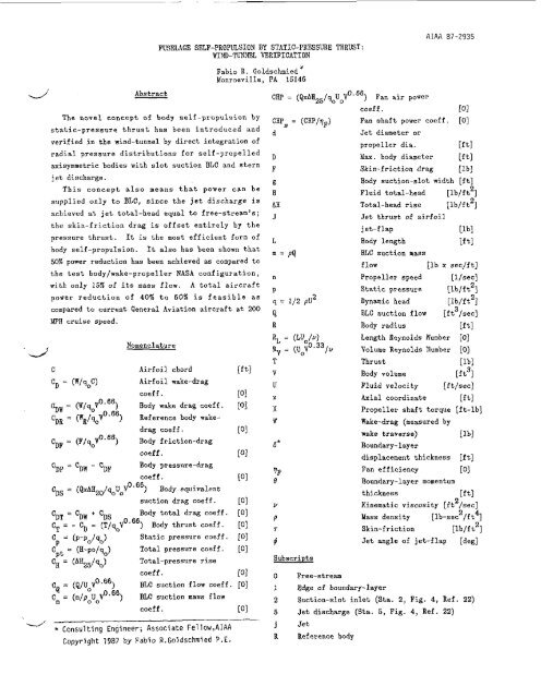
FUSELAGE SELF-PROPULSION BY STATIC-PRESSURE THRUST:<br />
WIND-TUNNEL VERIFICATION<br />
Fabio R. Goldschmied'<br />
Monroeville, PA 15146<br />
d' Abstract CAP = (QxAB25/qoUoV0~66) Fan air power<br />
.-.J<br />
- *<br />
The novel concept of body <strong>self</strong> -<strong>propulsion</strong> <strong>by</strong><br />
<strong>static</strong>-<strong>pressure</strong> <strong>thrust</strong> has been introduced and<br />
verified in the wind-tunnel <strong>by</strong> direct integration of<br />
radial <strong>pressure</strong> distributions for <strong>self</strong>-propelled<br />
&symmetric bodies with slot suction BLC and stern<br />
jet discharge.<br />
This concept also means that power can be<br />
supplied only to BLC, since the jet discharge is<br />
achieved at jet total-head equal to free-stream's;<br />
the skin-friction drag is offset entirely <strong>by</strong> the<br />
<strong>pressure</strong> <strong>thrust</strong>. It is the most efficient form of<br />
body <strong>self</strong>-<strong>propulsion</strong>. It also has been shown that<br />
50% power reduction has been achieved as compared to<br />
the test body/wake-propeller NASA configuration,<br />
with only 1% of its mass flow. A total aircraft<br />
power reduction of 40% to 60% is feasible as<br />
compared to current General Aviation aircraft at 200<br />
!E" cruise speed.<br />
CDF = (F/qoYo'")<br />
c~~ = 'DW C~~<br />
Cos = (QxAE20/~oUoV 0<br />
'Il' = 'DW + 'DS<br />
Nomenclature<br />
Airfoil chord<br />
Airfoil wake-drag<br />
coeff.<br />
Body wake drag coeff.<br />
Reference body wakedrag<br />
coeff .<br />
Body friction-drag<br />
coeff.<br />
Body <strong>pressure</strong>-drag<br />
coeff .<br />
66) Body equivalent<br />
suction drag coeff .<br />
Body total drag coeff.<br />
C - - CD =<br />
T-<br />
(T/%Vo.") Body <strong>thrust</strong> coeff.<br />
c = (P-Po/so) Static <strong>pressure</strong> coeff.<br />
P<br />
Cpt = (E-PO/%) Total <strong>pressure</strong> coeff.<br />
Cg = (AHz5/qo) Total-<strong>pressure</strong> rise<br />
coeff.<br />
CQ = (Q/UoV 0.66) BLC suction flow coeff<br />
Cm = (m/pouoV BLC suction mass flow<br />
coeff.<br />
Gms =<br />
AIAA 87-2935<br />
coef f . (01<br />
Fan shaft power coeff. [O]<br />
Jet diameter or<br />
propeller dia. [ftl<br />
Max. body diameter [ftl<br />
F Skin-friction drag [Ibl<br />
5 Body suction-slot width [it]<br />
E<br />
Fluid total-head [lb/ft2]<br />
bE<br />
Total-head rise [lh/ft2]<br />
Jet <strong>thrust</strong> of airfoil<br />
m = PQ<br />
jet-flap [Ibl<br />
Body length [ftl<br />
BLC suction mass<br />
flow [lb x secjft]<br />
Propeller speed [l/secl<br />
P<br />
2<br />
q = 1/2 pu<br />
Q<br />
Static <strong>pressure</strong><br />
Dynamic head<br />
BLC suction flow<br />
[lb/f t2]<br />
[l b/ft2]<br />
[ft3/sec]<br />
R Body radius [ftl<br />
RL = (LU0/4 Length Reynolds Number [O]<br />
Rv = (U0V0'33/~ Volume Reynolds Number [O]<br />
T Thrust Pbl<br />
V Body volume [ft31<br />
U Fluid velocity [f t/sec]<br />
x Axial coordinate [ftl<br />
x Propeller shaft torque [ft-lb]<br />
w Wake-drag (measured <strong>by</strong><br />
Subscripts<br />
0 Free-stream<br />
Consulting Engineer; Associate Fellow,AIAA j Jet<br />
Copyright 1987 <strong>by</strong> Fabio R.Goldschmied P.E. R Reference body<br />
wake traverse) [Ibl<br />
Boundary-layer<br />
displacement thickness [ft]<br />
Fan efficiency 101<br />
Boundary-layer momentum<br />
thickness<br />
[ftl<br />
2<br />
Kinematic viscosity [ft /set]<br />
2 4<br />
Mass density [lb-sec /ft ]<br />
Skin-friction [lb/f t2]<br />
Jet angle of jet-flap [deg]<br />
1 Edge of boundary-layer<br />
2 Suction-slot inlet (Sta. 2, Fig. 4, Ref. 22)<br />
5 Jet discharge (Sta. 5, Fig. 4, Ref. 22)