
Create successful ePaper yourself
Turn your PDF publications into a flip-book with our unique Google optimized e-Paper software.
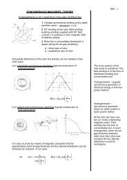
SINGLE–PHASE <strong>INDUCTION</strong> MOTORS<br />
THEORETICAL CONSIDERATIONS<br />
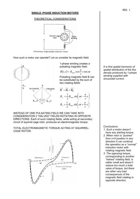
How such a motor can operate? Let us consider its magnetic field:<br />
1-phase winding creates a<br />
pulsating magnetic field:<br />
π<br />
B( x,<br />
t)<br />
= Bmax<br />
cos xsinωt<br />
τ<br />
Pulsating magnetic field B can<br />
be substituted by the sum of<br />
two rotating fields:<br />
B B B + =<br />
B f<br />
B b<br />
f<br />
b<br />
1 max<br />
⎛ π ⎞<br />
= B sin⎜ωt<br />
− x⎟<br />
2 ⎝ τ ⎠<br />
1 ⎛ π ⎞<br />
= Bmax<br />
sin⎜ωt<br />
+ x⎟<br />
2 ⎝ τ ⎠<br />
INSTEAD OF ONE PULSATING FIELD WE CAN TAKE INTO<br />
CONSIDERATION 2 “HALVED” FIELDS ROTATING IN OPPOSITE<br />
DIRECTIONS. Each of such rotating fields, while acting at secondary<br />
circuit of squirrel-cage rotor, produces an electromagnetic torque.<br />
TOTAL ELECTROMAGNETIC TORQUE ACTING AT SQUIRREL-<br />
CAGE ROTOR:<br />
IM3- 1<br />
It is first spatial harmonic of<br />
spatial distribution of the flux<br />
density produced by 1-phase<br />
winding supplied with<br />
sinusoidal current.<br />
Conclusions:<br />
1. Such a motor doesn’t<br />
have any starting torque.<br />
2. When rotor is “pushed”<br />
from n=0 position in any<br />
direction it can continue<br />
the operation as a “normal”<br />
induction motor with<br />
rotating magnetic field.<br />
3. The opposing torque,<br />
corresponding to another<br />
“halved” rotating field, is<br />
rather small and doesn’t<br />
reduce too much a total<br />
value of torque, but there<br />
are other very bad<br />
consequences of the<br />
magnetic field rotating in<br />
opposite direction.
We can now conclude some questions and answers:<br />
HOW TO ACHIEVE NON-ZER0 STARTING TORQUE?<br />
It is necessary to have rotating magnetic field.<br />
HOW TO ACHIEVE ANY ROTATING MAGNETIC FIELD?<br />
It is necessary to have multi-phase arrangement. For example<br />
3-PHASE SYSTEM: SYMMETRICAL PHASE AND CURRENT<br />
ARRANGEMENT!<br />
What about 2-PHASE SYSTEM?<br />
Let us consider two 1-phase windings with their axes displaced in space<br />
by 90 o :<br />
φ = φ sinωt<br />
m<br />
m max<br />
( ω α )<br />
φ = φ sin t +<br />
a<br />
a max<br />
The end of the vector of resultant flux Φ of two pulsating fluxes draws its<br />
locus. Can its length be constant?<br />
Φ =<br />
?<br />
φ<br />
2 2<br />
a<br />
+ φ<br />
m<br />
= const<br />
When locus of flux φ is circular the<br />
resultant magnetic field is<br />
ROTATING “CIRCULAR” FIELD,<br />
exactly the same as in case of 3 –<br />
phase symmetrical arrangement!<br />
This is the most required case!<br />
Φ = const when two following conditions are fulfilled:<br />
a)<br />
b)<br />
o<br />
α = 90 (displacement of fluxes & currents in time) and<br />
φ<br />
mmax<br />
= φ<br />
amax<br />
( also<br />
max amax<br />
I I<br />
m<br />
= when N<br />
m<br />
= N<br />
a<br />
)<br />
In other case the locus is elliptical<br />
“ELLIPTICAL”<br />
ROTATING FIELD<br />
PULSATING FIELD<br />
(one semi-axis of<br />
ellipse = 0 )<br />
when e.g. :<br />
max<br />
0 = φ<br />
a<br />
or<br />
α = 0<br />
IM3- 2
POSSIBLE REALIZATIONS OF 1-PHASE MOTORS<br />
IM3- 3<br />
SPLIT-PHASE MOTOR<br />
CAPACITOR-START<br />
MOTOR<br />
C = 20 ÷ 30<br />
C = 60 ÷ 100<br />
µF<br />
µF<br />
100 W<br />
750 W<br />
PERMANENT-SPLIT-<br />
CAPACITOR MOTOR<br />
(capacitor-run motor)<br />
TWO-VALUE-CAPACITOR<br />
MOTOR
NUMERICAL EXAMPLE<br />
A 250 W, 220 V, 50 Hz capacitor–start motor has the following winding<br />
impedances for the main and auxiliary windings at starting:<br />
Z m<br />
Z<br />
a<br />
= 18 + j14.<br />
8 [ Ω]<br />
= 38 + j14<br />
[ Ω]<br />
Find the value of starting capacitance that will place the main and<br />
auxiliary winding currents in quadrature at starting.<br />
1⎛<br />
14.<br />
8 ⎞<br />
ϕ<br />
o<br />
m<br />
= tan<br />
−<br />
⎜ ⎟ = 39.<br />
42<br />
⎝ 18 ⎠<br />
ϕ<br />
o o o<br />
a<br />
= 39. 42 − 90 = −50.<br />
58<br />
Z<br />
'<br />
a = 38 + j(<br />
14 − X<br />
C )<br />
14 X<br />
tan<br />
− 1⎛<br />
−<br />
C<br />
⎞<br />
⎜ ⎟ = −50.<br />
58<br />
o<br />
⎜ 38 ⎟<br />
⎝ ⎠<br />
14 − X C = −1.<br />
217<br />
38<br />
X = 60.<br />
2 Ω<br />
C<br />
10<br />
6<br />
10<br />
6<br />
C = = =<br />
X<br />
C<br />
⋅ 2πf<br />
60.<br />
2 ⋅ 2πf<br />
52.<br />
9<br />
µF<br />
IM3- 4