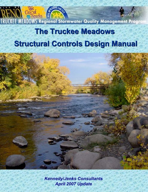
The Truckee Meadows Structural Controls Design ... - City of Sparks
The Truckee Meadows Structural Controls Design ... - City of Sparks
The Truckee Meadows Structural Controls Design ... - City of Sparks

You also want an ePaper? Increase the reach of your titles
YUMPU automatically turns print PDFs into web optimized ePapers that Google loves.
<strong>The</strong> <strong>Truckee</strong> <strong>Meadows</strong><br />
<strong>Structural</strong> <strong>Controls</strong> <strong>Design</strong> Manual<br />
Kennedy/Jenks Consultants<br />
April 2007 Update
<strong>Truckee</strong> <strong>Meadows</strong> <strong>Structural</strong> <strong>Controls</strong> <strong>Design</strong> Manual, April 2007 Update<br />
UPDATES AND ERRATA<br />
#1 - 29 April 2008<br />
Amend the BMP fact sheets in Section 6 <strong>of</strong> the above noted manual as follows:<br />
• Section 6: Change all instances <strong>of</strong> Ph to pH.<br />
• Page 6-21, Figure TC-20C. Side View. Bottom right text should read “1.5 inch Class<br />
D backfill Stone or Gravel”<br />
• Page 6-30, first bullet, insert after filter fabric: “or a pea gravel layer”<br />
• Page 6-31, second bullet should read 5-20% “Peat Moss <strong>of</strong> Certified Compost”<br />
• Page 6-33, Figure TC-30. All schematics should read “5-20% Peat Moss <strong>of</strong> Certified<br />
Compost”<br />
• Page 6-50, second bullet should read “4H:1V” or flatter.<br />
• Page 6-79, eighth bullet should read “See figures TC-64D and 64E.”
Table <strong>of</strong> Contents<br />
List <strong>of</strong> Tables................................................................................................................................ iii<br />
List <strong>of</strong> Figures............................................................................................................................... iii<br />
List <strong>of</strong> Appendices......................................................................................................................... v<br />
Acknowledgements...................................................................................................................... vi<br />
List <strong>of</strong> Acronyms..........................................................................................................................viii<br />
Glossary........................................................................................................................................ x<br />
Section 1: Introduction<br />
1.0 Historical Background .........................................................................1-1<br />
1.1 Purpose and Organization <strong>of</strong> the Manual............................................1-1<br />
1.2 Program Area......................................................................................1-3<br />
1.3 Relationship to Other Manuals and Handbooks..................................1-3<br />
1.4 Updates and Revisions .......................................................................1-3<br />
1.5 Comments and Distribution.................................................................1-4<br />
1.6 Disclaimer ...........................................................................................1-4<br />
Section 2: Storm Water Quality Management<br />
2.0 Environmental Impacts <strong>of</strong> Untreated Urban Storm Water Run<strong>of</strong>f .......2-1<br />
2.1 Storm Water Pollution and the <strong>Truckee</strong> <strong>Meadows</strong>..............................2-3<br />
2.2 NPDES Storm Water Permit Regulations ...........................................2-7<br />
2.3 Permissable Non-Storm Water Discharges.........................................2-9<br />
2.4 Storm Water Quality Hydrology <strong>of</strong> the <strong>Truckee</strong> <strong>Meadows</strong> ................2-10<br />
2.5 Evaluating Pollutants <strong>of</strong> Concern ......................................................2-14<br />
2.6 Identifying Candidate BMPs..............................................................2-14<br />
2.7 Regional Treatment <strong>Controls</strong> ............................................................2-17<br />
2.8 References and Additional Resource Information.............................2-18<br />
Section 3: <strong>The</strong> <strong>Truckee</strong> <strong>Meadows</strong> <strong>Structural</strong> <strong>Controls</strong> Program<br />
3.0 Legal Authority ....................................................................................3-1<br />
3.1 Local Policies and Procedures............................................................3-1<br />
3.1.1 Public Reporting........................................................................3-2<br />
3.1.2 Public Resources ......................................................................3-3<br />
3.2 Water Quality <strong>Design</strong> Criteria..............................................................3-4<br />
3.2.1 Sizing Criteria for Flow-Based Storm Water Treatment<br />
<strong>Controls</strong>...............................................................................................3-5<br />
3.2.2 Sizing Criteria for Volume-Based Storm Water Treatment<br />
<strong>Controls</strong>...............................................................................................3-6<br />
3.2.3 Diversion Structures..................................................................3-9<br />
<strong>Design</strong>ing Weirs for Flow-Based Treatment <strong>Controls</strong> 3-12<br />
<strong>Design</strong>ing Weirs for Volume-Based Treatment <strong>Controls</strong> 3-13<br />
<strong>Design</strong>ing Orifices for Volume-Based Treatment <strong>Controls</strong> 3-13<br />
<strong>Truckee</strong> <strong>Meadows</strong> Regional Stormwater Quality Management Program<br />
<strong>Structural</strong> <strong>Controls</strong> <strong>Design</strong> Manual, April 2007 Update<br />
Table <strong>of</strong> Contents Page i
<strong>Design</strong>ing Bypass Pipes for Volume-Based Treatment <strong>Controls</strong>....3-14<br />
3.2.4 Groundwater Recharge Considerations..................................3-17<br />
3.2.5 Combining Volume and Flow-Based BMPs ............................3-18<br />
3.2.6 Additional Storm Water Treatment Measures .........................3-18<br />
3.2.7 Vector <strong>Controls</strong>........................................................................3-18<br />
Section 4: Planning Principles and Site <strong>Design</strong><br />
4.0 Planning Principles..............................................................................4-1<br />
4.1 Site <strong>Design</strong>..........................................................................................4-2<br />
SC-10 Ro<strong>of</strong> Run<strong>of</strong>f <strong>Controls</strong>................................................................4-3<br />
SC-11 Efficient Irrigation .....................................................................4-6<br />
SC-12 Storm Drain Labeling ...............................................................4-8<br />
Section 5: Source <strong>Controls</strong><br />
5.0 Introduction .........................................................................................5-1<br />
5.1 Commercial/Industrial Area BMPs ......................................................5-1<br />
SC-20 Outdoor Material Storage.........................................................5-2<br />
SC-21 Outdoor Material Loading/Unloading .......................................5-4<br />
SC-22 Fueling Areas...........................................................................5-6<br />
SC-23 Outdoor Work, Maintenance and Wash Areas.........................5-8<br />
SC-24 Spill Prevention, Containment and Cleanup ..........................5-10<br />
SC-25 Waste Handling and Disposal................................................5-12<br />
5.2 Multi-Family Area BMPs....................................................................5-14<br />
SC-30 Vehicle Wash Areas...............................................................5-15<br />
SC-31 Waste Handling Areas ...........................................................5-16<br />
Section 6: Public Domain Treatment <strong>Controls</strong><br />
6.0 Introduction .........................................................................................6-1<br />
6.1 Vegetative Treatment Systems ...........................................................6-2<br />
TC-10 Vegetative Swales....................................................................6-3<br />
TC-11 Vegetative Buffer Strips............................................................6-8<br />
6.2 Infiltration Systems............................................................................6-13<br />
TC-20 Infiltration Trenches................................................................6-14<br />
TC-21 Infiltration Basins....................................................................6-21<br />
6.3 Bioretention Systems ........................................................................6-26<br />
TC-30 Landscape Detention .............................................................6-27<br />
6.4 Extended Detention Basins...............................................................6-31<br />
TC-40 Sedimentation Basins.............................................................6-32<br />
TC-41 Sand Filter Basins ..................................................................6-40<br />
6.5 Storm Water Ponds and Wetlands....................................................6-44<br />
TC-50 Storm Water Ponds................................................................6-45<br />
TC-51 Storm Water Wetlands ...........................................................6-49<br />
6.6 Media Filtration Systems...................................................................6-53<br />
TC-60 Surface Sand Filter.................................................................6-54<br />
TC-61 Underground Sand Filter........................................................6-60<br />
6.7 Porous Pavement<br />
TC-62(a) Porous Pavement Detention..............................................6-70<br />
TC-62(b) Open-Celled Block Paving.................................................6-75<br />
TC-62(c) Open-Jointed Block Paving...............................................6-80<br />
<strong>Truckee</strong> <strong>Meadows</strong> Regional Stormwater Quality Management Program<br />
<strong>Structural</strong> <strong>Controls</strong> <strong>Design</strong> Manual, April 2007 Update<br />
Table <strong>of</strong> Contents Page ii
TC-62(c) Porous Concrete and Asphalt Pavement.........................6-85<br />
TC-62(c) Porous Turf .....................................................................6-89<br />
TC-62(c) Porous Gravel..................................................................6-93<br />
TC-62(c) Open-Celled Plastic Grids................................................6-97<br />
6.8 Oil and Water Separators................................................................6-106<br />
TC-70 Oil and Water Separators.....................................................6-107<br />
Section 7: Manufactured (Proprietary) Treatment <strong>Controls</strong><br />
List <strong>of</strong> Tables<br />
7.0 Introduction .........................................................................................7-1<br />
MTC-10 Hydrodynamic Separators.....................................................7-2<br />
MTC-20 Wet Vaults.............................................................................7-6<br />
MTC-30 Catch Basin Inserts ...........................................................7-12<br />
MTC-40 Modular Wetlands ...............................................................7-17<br />
MTC-50 Media Filtration Systems.....................................................7-20<br />
MTC-60 Landscape Filtration Systems .............................................7-26<br />
MTC-70 Gross Solids Removal Device............................................. 7-30<br />
2-1 Pollutants Commonly Found in Urban Run<strong>of</strong>f<br />
2-2 Period <strong>of</strong> Record General Climate Summary – Precipitation, Reno WSFO Airport<br />
2-3 Anticipated and Potential Pollutants Generated by Land Use Type<br />
3-1 Run<strong>of</strong>f coefficients for the Rational Method<br />
3-2 Manning Roughness Coefficients for Open Channels<br />
TC-60A Sedimentation Basin <strong>Design</strong> Criteria<br />
TC-60B Sand Filter Basin <strong>Design</strong> Criteria<br />
TC-61A D.C. Type Underground Sand Filter <strong>Design</strong> Criteria<br />
TC-61B Delaware Type Underground Sand Filter <strong>Design</strong> Criteria<br />
List <strong>of</strong> Figures<br />
2-1 <strong>The</strong> hydrographic response <strong>of</strong> urbanization within a hypothetical watershed<br />
2-2 New Development in the <strong>Truckee</strong> <strong>Meadows</strong> from 1992 to 2002<br />
2-3 Annual average concentrations <strong>of</strong> total nitrogen (TN) and total phosphorous (TN)<br />
measured on the <strong>Truckee</strong> River from Mogul to Lockwood (2000 to 2004).<br />
2-4 Annual average concentrations <strong>of</strong> total dissolved solids (TDS) and Fecal Coliform<br />
measured on the <strong>Truckee</strong> River from Mogul to Lockwood (2000 to 2004).<br />
<strong>Truckee</strong> <strong>Meadows</strong> Regional Stormwater Quality Management Program<br />
<strong>Structural</strong> <strong>Controls</strong> <strong>Design</strong> Manual, April 2007 Update<br />
Table <strong>of</strong> Contents Page iii
2-5 Distribution <strong>of</strong> run<strong>of</strong>f producing storm events at the Reno Tahoe International Airport<br />
2-6 Precipitation Frequency Analysis <strong>of</strong> the run<strong>of</strong>f producing storm events at the Reno<br />
Tahoe International Airport<br />
3-1 Intensity-depth-duration curve for Region 1 <strong>of</strong> <strong>Sparks</strong> from the <strong>City</strong> <strong>of</strong> <strong>Sparks</strong><br />
Hydrologic Criteria and Drainage <strong>Design</strong> Manual, 1998<br />
3-2 Example <strong>of</strong> an underground pipe interceptor weir and/or orifice diversion structure for<br />
WQF or WQV treatment control measures<br />
3-3 Example <strong>of</strong> a surface channel diversion structure for flow or volume based treatment<br />
controls<br />
3-4 Example <strong>of</strong> an in-line underground sand filter with an overflow weir<br />
3-5 Example <strong>of</strong> an in-line treatment control measure with a bypass pipe<br />
SC-10 Example <strong>of</strong> a Sand Filter for ro<strong>of</strong> run<strong>of</strong>f control<br />
SC-12 Examples <strong>of</strong> storm drain labels<br />
TC-10A Typical design and structure <strong>of</strong> a Vegetated Swale<br />
TC-10B General design guidelines for a typical Vegetated Swale<br />
TC-11 General design guidelines for a typical Vegetated Buffer Strip<br />
TC-20A Example <strong>of</strong> an Infiltration Trench with an energy dissipation device and a bypass<br />
structure<br />
TC-20B Example <strong>of</strong> a median strip Infiltration Trench with a grass buffer strip<br />
TC-20C Example <strong>of</strong> a parking lot Infiltration Trench with a grass buffer strip<br />
TC-21 Example <strong>of</strong> a typical Infiltration Basin design<br />
TC-30 Schematic <strong>of</strong> a Landscape Detention facility<br />
TC-40A Typical components <strong>of</strong> a Sedimentation Basin<br />
TC-40B Example design <strong>of</strong> a sedimentation basin embankment and outlet structure<br />
TC-40C Example sedimentation basin outlet structure #1 – vertical plate with multiple orifices<br />
TC-40D Example sedimentation basin outlet structure #2 – perforated pipe<br />
TC-41 Example <strong>of</strong> a Sand Filter Basin design<br />
TC-50 Example <strong>of</strong> a Storm Water Pond<br />
TC-51 Example design <strong>of</strong> a Storm Water Wetland<br />
TC-60 Conceptual Surface Sand Filter design<br />
TC-61A Example <strong>of</strong> a D.C. type Underground Sand Filter<br />
TC-61B Cross-section <strong>of</strong> a D.C. type Underground Sand Filter<br />
TC-61C Example <strong>of</strong> a Delaware type Underground Sand Filter<br />
TC-61D Cross-sections <strong>of</strong> a Delaware type Underground Sand Filter showing dimensional<br />
relationships<br />
TC-64A Typical roadway applications for Porous Pavement<br />
<strong>Truckee</strong> <strong>Meadows</strong> Regional Stormwater Quality Management Program<br />
<strong>Structural</strong> <strong>Controls</strong> <strong>Design</strong> Manual, April 2007 Update<br />
Table <strong>of</strong> Contents Page iv
TC-64B Cross-section <strong>of</strong> typical porous pavement installation and different types <strong>of</strong> porous<br />
pavement<br />
TC-64C Typical porous pavement and drainage pipe configurations<br />
TC-64D View <strong>of</strong> a paver block installation showing perimeter wall and contained cells<br />
TC-64E Layout for underdrain system for porous pavement installations<br />
TC-70A Example design and structural information for a typical oil and water separator<br />
MTC-10A Vortechs<br />
MTC-10B Downstream Defender<br />
MTC-10C CDS Separator<br />
MTC-20A Type A System - BaySaver<br />
MTC-20B Type B System - Jensen StormVault<br />
MTC-20C Type C System - Stormceptor ®<br />
MTC-30A Examples <strong>of</strong> a basket type insert for a curb inlet catch basin and a box type insert for<br />
a vertical drop inlet<br />
MTC-30B Example <strong>of</strong> a box type catch basin insert<br />
MTC-30C Example <strong>of</strong> a box type insert for a curb inlet catch basin<br />
MTC-40 Example <strong>of</strong> a modular wetland<br />
MTC-50A Example <strong>of</strong> a vault type media filtration system<br />
MTC-50B Example <strong>of</strong> a media filter cartridge<br />
MTC-50C Example <strong>of</strong> a manhole media filtration system<br />
MTC-50D Example <strong>of</strong> a catch basin media filtration system<br />
MTC-60A Example <strong>of</strong> a landscape filtration system located between the street and the sidewalk<br />
MTC-60B Example <strong>of</strong> a landscape filtration system with an underdrain to convey infiltrate to the<br />
storm drain system<br />
MTC-70A Linear Radial Gross Solids Removal Device with an energy dissipating feature<br />
MTC-70B Example <strong>of</strong> a Linear Radial Device<br />
List <strong>of</strong> Appendices<br />
A <strong>Structural</strong> Control <strong>Design</strong> and Selection Matrix<br />
B <strong>Truckee</strong> <strong>Meadows</strong> <strong>Design</strong> Guidance Worksheets<br />
C District Health Department Vector Control Standards<br />
<strong>Truckee</strong> <strong>Meadows</strong> Regional Stormwater Quality Management Program<br />
<strong>Structural</strong> <strong>Controls</strong> <strong>Design</strong> Manual, April 2007 Update<br />
Table <strong>of</strong> Contents Page v
Acknowledgements<br />
<strong>The</strong> <strong>Truckee</strong> <strong>Meadows</strong> <strong>Structural</strong> <strong>Controls</strong> <strong>Design</strong> Manual was prepared under a contract with<br />
the <strong>City</strong> <strong>of</strong> Reno on behalf <strong>of</strong> the <strong>Truckee</strong> <strong>Meadows</strong> Storm Water Permit Coordinating<br />
Committee with funding provided by the Regional Water Planning Commission. <strong>The</strong> storm<br />
water committee members involved in the development <strong>of</strong> the January 2004 edition <strong>of</strong> the<br />
manual were:<br />
*Terri Svetich, P.E., Committee Chair *Kimble Corbridge, P.E.<br />
<strong>City</strong> <strong>of</strong> Reno, Sanitary Engineering Washoe County Engineering<br />
Shawn Gooch Chris Ennes<br />
<strong>City</strong> <strong>of</strong> <strong>Sparks</strong>, Flood Control Nevada Department <strong>of</strong> Transportation<br />
*Susan Ball Rothe, <strong>City</strong> <strong>of</strong> Reno<br />
Deputy <strong>City</strong> Attorney<br />
* identifies the committee members also involved in the development <strong>of</strong> the April 2007 Update<br />
This manual was developed to assist engineers, developers, contractors and <strong>City</strong> and County<br />
staff in the planning, design, construction, operation and maintenance <strong>of</strong> source and treatment<br />
controls for storm water quality improvement. <strong>Structural</strong> controls for water quality improvement<br />
are required at private and public development and redevelopment under the NPDES Municipal<br />
Stormwater Permit NVS000001. <strong>The</strong> Nevada Division <strong>of</strong> Environmental Protection (NDEP)<br />
issued this permit and the staff members responsible overseeing its implementation are:<br />
Clifford Lawson, P.E. Steve McG<strong>of</strong>f, P.E.<br />
NDEP, Bureau <strong>of</strong> Water Pollution Control NDEP, Bureau <strong>of</strong> Water Pollution Control<br />
Others who attended the public meetings and workshops and were involved in the development<br />
<strong>of</strong> this manual include the following:<br />
Andy Piplani, Peavine Construction<br />
Angela Huefle, AMEC Infrastructure<br />
Brendon Bennett, MacKay & Somps<br />
Candice Siwarga, Granite Construction Company<br />
Chris Robinson, P.E., <strong>City</strong> <strong>of</strong> Reno, Community Development<br />
Claudia Chambers, Kelley Erosion Control<br />
Debra Lemke, Huffman Control & Carpenter, Inc.<br />
Dennis Crouch, Bright Development<br />
Don Mahin, Washoe County<br />
Don Vetter, Innerwest<br />
Gabe Knox, Stantec Consulting<br />
Gail Prockish, Washoe County Dept. <strong>of</strong> Water Resources<br />
Gil Ellis, <strong>City</strong> <strong>of</strong> Reno, Environmental Control<br />
Glen Daily, P.E., <strong>City</strong> <strong>of</strong> Reno, Public Works Department<br />
Helen Godfrey, Kelley Erosion Control<br />
Jeanne Ruefer, Washoe County Dept. <strong>of</strong> Water Resources<br />
<strong>Truckee</strong> <strong>Meadows</strong> Regional Stormwater Quality Management Program<br />
<strong>Structural</strong> <strong>Controls</strong> <strong>Design</strong> Manual, April 2007 Update<br />
Acknowledgements Page vi
Jeff Jesch, CPESC, Hillside Development & Construction,<br />
Jenny Francis, Washoe-Storey Conservation District<br />
Jim Arden, Washoe-Storey Conservation District<br />
Jim Davenport, Mountain West Consulting<br />
Jim Shaffer, Washoe County District Health Department – Vector Control<br />
Jim Smitherman, Washoe County Dept. <strong>of</strong> Water Resources<br />
John Martini, P.E., <strong>City</strong> <strong>of</strong> <strong>Sparks</strong><br />
Judith Saurn, Washoe County District Health Department – Vector Control<br />
Judy Pipkin, Peavine Construction<br />
June Thomas, <strong>City</strong> <strong>of</strong> Reno<br />
Keith Fegert, SunRoc Inc.<br />
Kris Klein, P.E., Washoe County Engineering<br />
Larry Fowler, Silver State Barricade<br />
Lee Carson, <strong>City</strong> <strong>of</strong> <strong>Sparks</strong>, Environmental Control<br />
Mark Hausner, Washoe-Storey Conservation District<br />
Mark Sullivan, AGC<br />
Mel Quenemoen, Storey County<br />
Merlin Waite, Centrex Homes<br />
Michael Rosen, United States Geological Survey<br />
Mike Cavanaugh, Unlimited Concrete<br />
Mike Widmer, Washoe County Dept. <strong>of</strong> Water Resources<br />
Paul Urban, P.E., Washoe County Dept. <strong>of</strong> Water Resources<br />
Penny Oteri, <strong>City</strong> <strong>of</strong> Reno, Environmental Control<br />
Ray Foote, Unlimited Concrete<br />
Robert Gottsacker, <strong>City</strong> <strong>of</strong> Reno<br />
Ryan Bird, Sierra Pacific Power Company<br />
Sara Peterson, Jensen Precast<br />
Sarah Bergeron, Jensen Precast<br />
Scott Monsen, Washoe County District Health Department – Vector Control<br />
Scott Schoenfeld, P.E., Centex Homes<br />
Susan Donaldson, Ph.D., Nevada Cooperative Extension<br />
Susan Hood, Washoe County Dept. <strong>of</strong> Water Resources<br />
Tim Rowe, United States Geological Survey<br />
Toby Ebens, <strong>City</strong> <strong>of</strong> <strong>Sparks</strong>, Environmental Control<br />
Tom Adams, Nevada Department <strong>of</strong> Transportation<br />
Tom Hausner, Washoe-Storey Conservation District<br />
Tom Walbom, Granite Construction Company<br />
Trina Magoon, Stantec Consulting<br />
Warren Call, Washoe County Regional Transportation Commission<br />
<strong>The</strong> following staff at Kennedy/Jenks Consultants were involved in the preparation <strong>of</strong> the 2004<br />
and 2007 editions <strong>of</strong> this manual (under Job Nos. 007012.02 and 0595036).: Chris Conway,<br />
CPSWQ, Christine Kirick, Lynn Orphan, P.E., Christian Heinbaugh, Susan Strachan, Ed<br />
Childers, P.E., Jim Litchfield, Chris Johnson, Ron Overmyer, Pat Hamilton, Maggie Hack, Karen<br />
Siegel, Chris Anderson, P.E., Jeanette Dubois and Karin Peternel.<br />
In addition, Kennedy/Jenks would like to acknowledge the assistance <strong>of</strong> Ben Urbonas, P.E.,<br />
with the Urban Drainage & Flood Control District, and Larry Johnson and Dal Hunter, PH.D.,<br />
P.E. with Black Eagle Consulting.<br />
<strong>Truckee</strong> <strong>Meadows</strong> Regional Stormwater Quality Management Program<br />
<strong>Structural</strong> <strong>Controls</strong> <strong>Design</strong> Manual, April 2007 Update<br />
Acknowledgements Page vii
List <strong>of</strong> Acronyms<br />
AASHTO American Association <strong>of</strong> State Highway and Transportation Officials<br />
ASTM American Society for Testing and Materials<br />
BMP Best Management Practice<br />
CASQA California Stormwater Quality Association<br />
CFR Code <strong>of</strong> Federal Regulations<br />
cfs Cubic Feet per Second<br />
CWA Clean Water Act<br />
ECS Evaporative Control Systems, Inc.<br />
EPA U.S. Environmental Protection Agency<br />
LID Low Impact Development<br />
MDE Maryland Department <strong>of</strong> the Environment<br />
MEP Maximum Extent Practicable<br />
MIT Minimum Inter-event Time<br />
MS4 Municipal Separate Storm Sewer System<br />
NDEP Nevada Division <strong>of</strong> Environmental Protection<br />
NDF Nevada Division <strong>of</strong> Forestry<br />
NDOT Nevada Department <strong>of</strong> Transportation<br />
NPDES National Pollutant Discharge Elimination System<br />
NRCS National Resource Conservation Service<br />
NURP Nationwide Urban Run<strong>of</strong>f Program<br />
NWS National Weather Service<br />
PAG Pr<strong>of</strong>essional Advisory Group<br />
PAHs Polycyclic aromatic hydrocarbons<br />
PCBs Polychlorinated biphenyls<br />
PMF Probable Maximum Flood<br />
RSWQMP Regional Stormwater Quality Management Program<br />
RWPC Regional Water Planning Commission<br />
SPF Standard Project Flood<br />
SUSMP Standard Urban Stormwater Mitigation Plan<br />
SWPPP Storm Water Pollution Prevention Plan<br />
TMDL Total Maximum Daily Load<br />
<strong>Truckee</strong> <strong>Meadows</strong> Regional Stormwater Quality Management Program<br />
<strong>Structural</strong> <strong>Controls</strong> <strong>Design</strong> Manual, April 2007 Update<br />
List <strong>of</strong> Acronyms Page viii
TMWA <strong>Truckee</strong> <strong>Meadows</strong> Water Authority<br />
TSS Total Suspended Solids<br />
UDFCD Urban Drainage and Flood Control District<br />
UIC Underground Injection Control<br />
WQF Water Quality Flow<br />
WQV Water Quality Volume<br />
WRCC Western Regional Climate Center<br />
WSCD Washoe Storey Conservation District<br />
<strong>Truckee</strong> <strong>Meadows</strong> Regional Stormwater Quality Management Program<br />
<strong>Structural</strong> <strong>Controls</strong> <strong>Design</strong> Manual, April 2007 Update<br />
List <strong>of</strong> Acronyms Page ix
Glossary<br />
Anti-Seep Collar: An impermeable diaphragm, usually <strong>of</strong> sheet metal or concrete, constructed<br />
within the zone <strong>of</strong> saturation along the conduit <strong>of</strong> a principal spillway or outlet, installed to<br />
prevent piping or seepage along the conduit.<br />
Aquatic Bench: A 10 to 15 foot wide bench which is located around the inside perimeter <strong>of</strong> a<br />
permanent pool and is normally vegetated with aquatic plants; the goal is to provide pollutant<br />
removal and enhance safety in areas using storm water pond storm water practices.<br />
Baffles: Guides, grids, grating or similar devices placed in a pond to deflect or regulate flow<br />
and create a longer flow path.<br />
Berm: A shelf that breaks the continuity <strong>of</strong> a slope; a linear embankment or dike.<br />
Best Available Technology Economically Achievable (BAT): Technology-based standard<br />
established by the Clean Water Act (CWA) as the most appropriate means available on a<br />
national basis for controlling the direct discharge <strong>of</strong> pollutants to waters <strong>of</strong> the United States.<br />
Best Management Practices (BMPs): Schedules <strong>of</strong> activities, prohibitions <strong>of</strong> practices,<br />
maintenance procedures, structural devices and other management practices to prevent or<br />
reduce the discharge <strong>of</strong> pollutants to waters <strong>of</strong> the United States.<br />
Biochemical Oxygen Demand (BOD): A measurement <strong>of</strong> the amount <strong>of</strong> oxygen utilized by<br />
the decomposition <strong>of</strong> organic material, over a specified time period (usually 5 days) in a water<br />
sample.<br />
Bi<strong>of</strong>ilters: Grass depression areas such as engineered channels or swales that are used to<br />
collect and filter urban storm water.<br />
Bioretention: A water quality practice that utilizes landscaping and soils to treat urban run<strong>of</strong>f<br />
by collecting it in shallow depressions, before filtering through a fabricated planting soil media.<br />
Buffer: An area adjacent to a shoreline, wetland or stream where development is restricted or<br />
prohibited.<br />
Check Dam: A small dam constructed in a swale or other small watercourse to decrease the<br />
stream flow velocity (by reducing the channel gradient), minimize channel scour, and promote<br />
deposition <strong>of</strong> sediment.<br />
Clean Water Act (CWA): Formerly known as the Federal Water Pollution Act. Legislation,<br />
which provides statutory authority for both NPDES pretreatment and storm water programs.<br />
Detention: <strong>The</strong> temporary storage <strong>of</strong> storm run<strong>of</strong>f in a storm water practice with the goals <strong>of</strong><br />
controlling peak discharge rates and providing gravity settling <strong>of</strong> pollutants.<br />
Detention Structure: A structure constructed for the purpose <strong>of</strong> temporary storage <strong>of</strong> stream<br />
flow or surface run<strong>of</strong>f and gradual release <strong>of</strong> stored water at controlled rates.<br />
Discharge: <strong>The</strong> direct or indirect entry <strong>of</strong> storm water or non-storm water into the storm drain<br />
system or a receiving water body. This term can also reference the pollutants being discharged<br />
from an activity or operation into storm water and/or non-storm water.<br />
<strong>Truckee</strong> <strong>Meadows</strong> Regional Storm water Quality Management Program<br />
<strong>Structural</strong> <strong>Controls</strong> <strong>Design</strong> Manual, April 2007 Update<br />
Glossary Page x
Drainage Area: An area that contributes all precipitation falling within its boundaries to a single<br />
common or outflow point.<br />
Energy Dissipator: A designed device such as an apron <strong>of</strong> rip-rap or a concrete structure<br />
placed at the end <strong>of</strong> a water transmitting apparatus such as pipe, paved ditch or paved chute for<br />
the purpose <strong>of</strong> reducing the velocity, energy and turbulence <strong>of</strong> the discharged water.<br />
Erosion: Detachment and movement <strong>of</strong> soil or rock fragments by water, wind, ice or gravity.<br />
Extended Detention: A storm water design feature that provides for the gradual release <strong>of</strong> a<br />
volume <strong>of</strong> water over a 12 to 48 hour interval in order to increase settling <strong>of</strong> urban pollutants and<br />
protect downstream channels from frequent storm events.<br />
Filter Media: <strong>The</strong> sand, soil, or other organic material in a filtration device used to provide a<br />
permeable surface for pollutant and sediment removal.<br />
Filter Strips: A vegetated area that treats sheetflow and/or interflow by removing sediment and<br />
other pollutants. <strong>The</strong> area may be grass-covered, forested or <strong>of</strong> mixed vegetative cover.<br />
Fines (Soil): Generally refers to the silt and clay size particles in soil.<br />
General Permit: An NPDES permit issued under 40 CFR 122.28 that authorizes a category <strong>of</strong><br />
discharges under the CWA within a geographical area. A general permit is not specifically<br />
tailored for an individual discharger.<br />
Hazardous Substance: Any substance, other than oil, which, when discharged in any<br />
quantities into waters <strong>of</strong> the U.S., presents an imminent and substantial danger to the public<br />
health or welfare, including but not limited to fish, shellfish, wildlife, shorelines and beaches<br />
(Section 311 <strong>of</strong> the CWA); identified by EPA as the pollutants listed under 40 CFR Part 116.<br />
Heavy Metals: Metallic elements with high atomic weights (e.g. mercury, chromium, cadmium,<br />
arsenic, and lead) that can damage living things at low concentrations and tend to accumulate<br />
in the food chain.<br />
Illicit Connections: Illegal and/or unauthorized connections that result in untreated wastewater<br />
discharges into storm drainage systems and receiving waters.<br />
Illicit Discharge: Any discharge to a municipal separate storm sewer system that is not<br />
composed entirely <strong>of</strong> storm water, except for discharges allowed under an NPDES permit or<br />
waters used for certain emergency situations.<br />
Impervious: <strong>The</strong> characteristic <strong>of</strong> a material, which prevents the infiltration or passage <strong>of</strong> liquid<br />
through it. This may apply to roads, streets, driveways, parking lots, ro<strong>of</strong>tops, patios and<br />
sidewalks.<br />
Infiltration Rate: <strong>The</strong> rate at which water percolates into the subsoil measured in inches per<br />
hour.<br />
In-Line: A storm water management system designed to manage storm water in its original<br />
stream or drainage channel.<br />
Manufactured (proprietary) treatment controls: Patented devices that are engineered,<br />
constructed and distributed by private companies.<br />
<strong>Truckee</strong> <strong>Meadows</strong> Regional Storm water Quality Management Program<br />
<strong>Structural</strong> <strong>Controls</strong> <strong>Design</strong> Manual, April 2007 Update<br />
Glossary Page xi
Municipal Separate Storm Sewer System (MS4): A conveyance or system <strong>of</strong> conveyances<br />
(including roads with drainage systems, municipal streets, catch basins, curbs, gutters, ditches,<br />
man-made channels, or storm drains) owned and operated by a state, county, city, town,<br />
district, association, or other public body (created by or pursuant to state law) having jurisdiction<br />
over the disposal <strong>of</strong> sewage, industrial wastes, storm water, or other wastes, that discharges to<br />
waters <strong>of</strong> the United States. [40 CFR 122.26(b)(8)].<br />
Municipal Storm water Permit: An NPDES permit issued to municipalities to regulate<br />
discharges from municipal separate storm sewers for compliance with EPA established water<br />
quality standards and/or to specify specific storm water control strategies.<br />
National Pollutant Discharge Elimination System (NPDES): <strong>The</strong> national program for<br />
issuing, modifying, revoking and reissuing, terminating, monitoring and enforcing permits, and<br />
imposing and enforcing pretreatment requirements, under Sections 307, 318, 402, and 405 <strong>of</strong><br />
the CWA.<br />
Non-Point Source Pollution: Unlike pollution from industrial and sewage treatment plants,<br />
non-point source (NPS) pollution comes from many diffuse sources. NPS pollution is caused by<br />
rainfall or snowmelt moving over the ground that picks up and transports natural and humanmade<br />
pollutants, finally depositing them into lakes, rivers, wetlands, coastal waters, and<br />
underground sources <strong>of</strong> drinking water. Common non-point sources are agriculture, forestry,<br />
urban, mining, construction, dams, channels, land disposal, saltwater intrusion, and city streets.<br />
Non-Storm Water Discharges: Flows or discharges that are not entirely composed <strong>of</strong> storm<br />
water. <strong>The</strong>se may include but are not limited to uncontaminated groundwater, natural springs,<br />
car washing, air conditioner condensate, and hydrant flushing water.<br />
Non-<strong>Structural</strong> Storm Water Practices (or BMPs): Management practices and measures<br />
designed to reduce pollutant levels in storm water, which do not require extensive construction<br />
efforts, and promote pollutant reduction by eliminating the pollutant source.<br />
Off-Line: A storm water management system designed to manage a storm event by diverting a<br />
percentage <strong>of</strong> storm water events from a stream or storm drainage system.<br />
One Hundred Year Storm: A precipitation event, which occurs on average once every 100<br />
years or statistically has a 1% chance on average <strong>of</strong> occurring in a given year.<br />
Open Space: A portion <strong>of</strong> a development site, which is permanently set aside for public or<br />
private use and will not be developed with homes. <strong>The</strong> space may be used for passive or active<br />
recreation, or may be reserved to protect or buffer natural areas.<br />
Ordinance: A law, a statute, a decree enacted by a municipal body, such as a city council or<br />
county commission. Ordinances <strong>of</strong>ten govern matters not already covered by state or federal<br />
laws (such as local zoning, safety and building regulations), but may also be used to require<br />
stricter standards in local communities than those imposed by state or federal law.<br />
Organic Filter: A filtering practice that uses an organic medium such as peat or compost in the<br />
filter bed to filter storm water run<strong>of</strong>f.<br />
Outfall: <strong>The</strong> point where water discharges from a conduit, pipe, or drain to a stream, river, lake<br />
or another waterbody.<br />
Outlet: <strong>The</strong> point at which water discharges from a structure such as a basin, a trench or a<br />
concrete structure to another structure or a pipe or channel.<br />
<strong>Truckee</strong> <strong>Meadows</strong> Regional Storm water Quality Management Program<br />
<strong>Structural</strong> <strong>Controls</strong> <strong>Design</strong> Manual, April 2007 Update<br />
Glossary Page xii
Overflow Chamber: A design feature <strong>of</strong> some on-line storm water treatment practices that<br />
captures larger flows than are not treated by the practice, and passes them to the storm drain<br />
system.<br />
Peak Discharge (Flow Rate): <strong>The</strong> maximum instantaneous rate <strong>of</strong> flow during a storm, usually<br />
in reference to a specific design storm event.<br />
Perennial Stream: A stream channel that has running water throughout the year.<br />
Permeability: <strong>The</strong> rate <strong>of</strong> water movement through the soil column under saturated conditions.<br />
Pervious: A property <strong>of</strong> a material that allows for the passage <strong>of</strong> liquid through it.<br />
Point Source: Any discernible, confined, and discrete conveyance or container, including but<br />
not limited to, any pipe, ditch, channel, tunnel, conduit, well, or tank from which pollutants are or<br />
may be discharged. This term does not include return flows from irrigated agriculture or<br />
agricultural storm water run<strong>of</strong>f.<br />
Pollutant: Dredged spoil, solid waste, incinerator residue, filter backwash, sewage, garbage,<br />
sewage sludge, munitions, chemical wastes, biological materials, radioactive materials, heat,<br />
wrecked or discarded equipment, rock, sand, dirt, and industrial, municipal, and agricultural<br />
waste discharged into water [40 CFR 122.2].<br />
Porosity: Ratio <strong>of</strong> pore volume to total solids volume.<br />
Porous Pavement: Permeable pavement surface with an underlying stone reservoir to<br />
temporarily store surface run<strong>of</strong>f before it infiltrates into the subsoil. It can be used to replace<br />
asphalt and concrete and can be used for driveways, parking lots and walkways.<br />
Pretreatment: Techniques employed in storm water practices to provide storage or filtering to<br />
help trap coarse materials before they enter the system.<br />
Public domain treatment controls: Devices/facilities that can be designed by an engineer<br />
and have been implemented and tested by numerous communities throughout the nation.<br />
Rain Barrel: A temporary storage device connected to a ro<strong>of</strong> downspout, typically including a<br />
hose attachment to allow for reuse <strong>of</strong> ro<strong>of</strong>top run<strong>of</strong>f.<br />
Rational Method: Used to determine peak flow rates for drainage areas <strong>of</strong> 100 acres or less,<br />
and 25 acres or less where the composite run<strong>of</strong>f coefficient is 0.50 or less.<br />
Recharge Rate: <strong>The</strong> annual amount <strong>of</strong> rainfall that contributes to groundwater.<br />
Redevelopment: Land-disturbing activity that results in the addition or replacement <strong>of</strong><br />
impervious surface area on an already developed site. This may include the expansion <strong>of</strong> a<br />
building footprint, changes that are not part <strong>of</strong> routine maintenance, change to or an addition <strong>of</strong><br />
a structure, and any related land disturbing activities.<br />
Retention: <strong>The</strong> amount <strong>of</strong> precipitation on a drainage area that does not escape as run<strong>of</strong>f. It is<br />
the difference between total precipitation and total run<strong>of</strong>f. It also refers to the amount <strong>of</strong> storm<br />
water that is retained in a treatment control and is not slowly released to the storm drain system.<br />
Retr<strong>of</strong>it: <strong>The</strong> installation <strong>of</strong> a new storm water practice or the improvement <strong>of</strong> an existing one<br />
in a previously developed area.<br />
<strong>Truckee</strong> <strong>Meadows</strong> Regional Storm water Quality Management Program<br />
<strong>Structural</strong> <strong>Controls</strong> <strong>Design</strong> Manual, April 2007 Update<br />
Glossary Page xiii
Riparian: <strong>The</strong> land area that borders a stream or river and which directly affects and is affected<br />
by the water quality. This land area <strong>of</strong>ten coincides with the maximum water surface elevation <strong>of</strong><br />
the 100-year storm.<br />
Riser: A vertical pipe which extends from the bottom <strong>of</strong> a storm water treatment control that<br />
houses discharge control devices such as weirs, orifices or multiple perforations.<br />
Run<strong>of</strong>f: That part <strong>of</strong> precipitation, snow melt, irrigation or wash water that runs <strong>of</strong>f the land into<br />
the storm drain system, streams or other surface-waters.<br />
Run-on: <strong>The</strong> flow <strong>of</strong> storm water from an upgradient area onto an area where potential<br />
pollutants may exist.<br />
Sanitary Sewer: A pipe or conduit (sewer) intended to carry wastewater or water-borne wastes<br />
from homes, businesses, and industries to the publicly owned treatment works (POTW) facility.<br />
Secondary Containment: A containment that is external and separate from the primary<br />
containment (concrete dike, wall, barrier, berm, bin, drum, or tank).<br />
Sediment: Solid particulate material, both mineral and organic, that can be transported from its<br />
site <strong>of</strong> origin by air, water, gravity, or ice.<br />
Sedimentation Chamber: A section <strong>of</strong> a storm water treatment control that provides for the<br />
settling out <strong>of</strong> relatively large sediment particles from suspension in storm water.<br />
Setbacks: <strong>The</strong> minimum distance requirements for location <strong>of</strong> a structural storm water practice<br />
in relation to roads, wells, septic fields, other structures.<br />
Sheet Flow: Water, usually storm run<strong>of</strong>f, flowing in a thin layer over the ground surface prior to<br />
the development <strong>of</strong> channelized flow.<br />
Side Slopes: <strong>The</strong> slope <strong>of</strong> the sides <strong>of</strong> a channel, dam or embankment. It is customary to<br />
name the horizontal distance first, as 3H:1V, meaning a horizontal distance <strong>of</strong> 3 feet to 1 foot<br />
vertical.<br />
Source controls: Measures and practices that emphasize reducing or eliminating pollutants in<br />
storm water run<strong>of</strong>f at their source by reducing run<strong>of</strong>f and potential pollutant exposure to rainfall<br />
and run<strong>of</strong>f.<br />
Spillway: An open or closed channel, or both, used to safely convey excess water from a<br />
basin, pond or reservoir over a dam or embankment.<br />
Stilling Basin: An open structure or excavation at the foot <strong>of</strong> an outfall, conduit, chute, drop, or<br />
spillway to reduce the energy <strong>of</strong> the descending stream <strong>of</strong> water.<br />
Storm Water = Stormwater: Rain and snow melt run<strong>of</strong>f and drainage associated with<br />
precipitation events [40 CFR 122.26(b)(13)].<br />
Storm Water Hot Spots: Land-uses or activities that generate highly contaminated run<strong>of</strong>f.<br />
Examples include fueling stations and airport de-icing facilities.<br />
Storm Water Management: <strong>The</strong> process <strong>of</strong> collecting, conveying, storing, treating, and<br />
disposing <strong>of</strong> storm water to ensure control <strong>of</strong> the magnitude and frequency <strong>of</strong> run<strong>of</strong>f to minimize<br />
the hazards associated with flooding and the impact on water quality caused by manmade<br />
changes to the land.<br />
<strong>Truckee</strong> <strong>Meadows</strong> Regional Storm water Quality Management Program<br />
<strong>Structural</strong> <strong>Controls</strong> <strong>Design</strong> Manual, April 2007 Update<br />
Glossary Page xiv
Storm Water Pollution Prevention Plan (SWPPP): A written document that describes the<br />
activities required to control the discharge <strong>of</strong> pollutants in storm water and non-storm water<br />
run<strong>of</strong>f. It is intended to facilitate a process whereby the operator evaluates potential pollutant<br />
sources at the site and selects and implements appropriate BMPs.<br />
Stream Buffers: Zones <strong>of</strong> variable width, which are located along both sides <strong>of</strong> a stream and<br />
are designed to provide a protective natural area along a stream corridor.<br />
<strong>Structural</strong> Treatment <strong>Controls</strong>: Devices that are constructed to provide temporary storage<br />
and treatment <strong>of</strong> storm water run<strong>of</strong>f and non-storm water flows. <strong>The</strong>y use physical, biological<br />
and/or chemical processes to remove pollutants that have already impacted storm water run<strong>of</strong>f<br />
and non-storm water flows.<br />
Toe (<strong>of</strong> slope): Where the slope stops or levels out. Bottom <strong>of</strong> the slope.<br />
Total Maximum Daily Load (TMDL): A tool for establishing the allowable loadings <strong>of</strong> a given<br />
pollutant in a surface water resource to meet predetermined water quality standards.<br />
Total Suspended Solids (TSS): A measure <strong>of</strong> the filterable solids present in a water sample,<br />
as determined by the method specified in 40 CFR Part 136.<br />
Trash Rack: Grill, grate or other device at the intake <strong>of</strong> a channel, pipe, drain or spillway for the<br />
purpose <strong>of</strong> preventing oversized debris from entering the structure.<br />
Ultra-Urban: A region dominated by highly developed areas in which very little pervious<br />
surface exists.<br />
Variance: A special allowance granted to a developer, which permits the use <strong>of</strong> designs<br />
different from the requirements <strong>of</strong> the current code.<br />
Water Quality Standard: A law or regulation that consists <strong>of</strong> the beneficial use or uses <strong>of</strong> a<br />
waterbody, the numeric and narrative water quality criteria that are necessary to protect the use<br />
or uses <strong>of</strong> that particular waterbody, and an antidegradation statement.<br />
Water Quality Flow Rate (WQF): <strong>The</strong> flow rate representing frequently occurring rainfall/run<strong>of</strong>f<br />
events determined using the Rational Method for the 2-year storm event and the drainage area<br />
connected to the BMP.<br />
Water Quality Volume (WQV): <strong>The</strong> storage volume required to capture and treat 90% <strong>of</strong> the<br />
average annual storm water run<strong>of</strong>f events.<br />
Watershed: All the land area that contributes run<strong>of</strong>f to a particular point along a waterway.<br />
Sources:<br />
<strong>The</strong> <strong>City</strong> <strong>of</strong> Reno Municipal Code, Section 12.16.820 Definitions.<br />
<strong>The</strong> Storm water Manager’s Resource Center, Glossary, http://www.stormwatercenter.net/<br />
<strong>The</strong> U.S. Environmental Protection Agency, NPDES Glossary<br />
http://cfpub.epa.gov/npdes/glossary.cfm<br />
<strong>The</strong> U.S. Environmental Protection Agency, Terms <strong>of</strong> the Environment<br />
http://www.epa.gov/OCEPAterms/nterms.html<br />
<strong>Truckee</strong> <strong>Meadows</strong> Regional Storm water Quality Management Program<br />
<strong>Structural</strong> <strong>Controls</strong> <strong>Design</strong> Manual, April 2007 Update<br />
Glossary Page xv
Section 1<br />
Introduction
Section 1: Introduction<br />
1.0 Historical Background<br />
<strong>The</strong> development <strong>of</strong> the <strong>Truckee</strong> <strong>Meadows</strong> <strong>Structural</strong> <strong>Controls</strong> <strong>Design</strong> Manual began in January<br />
2000 when the Nevada Division <strong>of</strong> Environmental Protection (NDEP) issued a municipal storm<br />
water discharge permit to the <strong>City</strong> <strong>of</strong> Reno, the <strong>City</strong> <strong>of</strong> <strong>Sparks</strong>, Washoe County, and the Nevada<br />
Department <strong>of</strong> Transportation (NDOT). NDEP’s permit, referred to hereinafter as the <strong>Truckee</strong><br />
<strong>Meadows</strong> Municipal Permit, is a requirement <strong>of</strong> the National Pollutant Discharge Elimination<br />
System (NPDES) storm water program administered by the U.S. Environmental Protection<br />
Agency (U.S. EPA). One <strong>of</strong> the requirements <strong>of</strong> the <strong>Truckee</strong> <strong>Meadows</strong> Municipal Permit was<br />
the development and implementation <strong>of</strong> a Regional Storm Water Quality Management Program<br />
(RSWQMP) that provided a framework for reducing pollutants in municipal storm water<br />
discharges to the <strong>Truckee</strong> River, its tributaries, and the playa lakes <strong>of</strong> the north valleys. <strong>The</strong><br />
RSWQMP was finalized and adopted by the Cities, the County, NDOT in September 2001.<br />
<strong>The</strong> <strong>Truckee</strong> <strong>Meadows</strong> Storm Water Permit Coordinating Committee, which consists <strong>of</strong><br />
representatives from the Cities, the County, NDOT, is responsible for managing the<br />
implementation <strong>of</strong> the RSWQMP. <strong>The</strong> RSWQMP calls for the development <strong>of</strong> nine program<br />
elements to address the requirements <strong>of</strong> the <strong>Truckee</strong> <strong>Meadows</strong> Municipal Permit, including a<br />
program to implement storm water quality improvement structures and landscape design<br />
features (a.k.a. structural controls and Low Impact Development practices) in new development<br />
and redevelopment projects. Under this program each agency is responsible for their own<br />
ordinances, plan review, and inspection and maintenance <strong>of</strong> structural controls and LID<br />
practices within their jurisdiction. <strong>The</strong> program includes the development, adoption and<br />
implementation <strong>of</strong> a regional <strong>Structural</strong> <strong>Controls</strong> <strong>Design</strong> Manual. This manual has been<br />
developed for the <strong>City</strong> <strong>of</strong> Reno, the <strong>City</strong> <strong>of</strong> <strong>Sparks</strong> and Washoe County, with funding provided<br />
by the Regional Water Planning Commission.<br />
In February 2003, the Storm Water Permit Coordinating Committee began the process <strong>of</strong><br />
developing a regional <strong>Structural</strong> <strong>Controls</strong> <strong>Design</strong> Guidance Manual. To develop the manual, the<br />
committee conducted a series <strong>of</strong> public meetings and workshops to discuss the following:<br />
<strong>The</strong> NDEP and the U.S. EPA requirements for a local program;<br />
<strong>Structural</strong> <strong>Controls</strong> Programs and Storm Water <strong>Design</strong> Guidance Manuals in other<br />
communities;<br />
<strong>The</strong> preferred format <strong>of</strong> the manual and the recommended suite <strong>of</strong> structural controls for the<br />
<strong>Truckee</strong> <strong>Meadows</strong>;<br />
Development <strong>of</strong> performance standards and local policies and procedures;<br />
Concurrent activities <strong>of</strong> the NDEP and the U.S. EPA, other related local programs; and<br />
Comments and concerns <strong>of</strong> the general public.<br />
<strong>Truckee</strong> <strong>Meadows</strong> Regional Storm Water Quality Management Program<br />
<strong>Structural</strong> <strong>Controls</strong> <strong>Design</strong> Manual, April 2007 Update<br />
Section 1 – Introduction Page 1 - 1
<strong>The</strong>se elements were incorporated into the January 2004 edition <strong>of</strong> the <strong>Truckee</strong> <strong>Meadows</strong><br />
<strong>Structural</strong> <strong>Controls</strong> <strong>Design</strong> Manual. <strong>The</strong> fourth permittee <strong>of</strong> the 2000 <strong>Truckee</strong> <strong>Meadows</strong><br />
Municipal Permit, NDOT, independently developed its own design guidance for structural<br />
controls at NDOT owned properties and projects throughout Nevada. NDOT’s design guidance<br />
for structural controls were approved and finalized in 2004 and are presented within the NDOT<br />
Planning and <strong>Design</strong> Guide which can be accessed online at:<br />
http://www.nevadadot.com/reports_pubs/Water_Quality/pdfs/PDG_AppendixB.pdf<br />
http://www.nevadadot.com/reports_pubs/Water_Quality/pdfs/PDG_AppendixC.pdf<br />
Per the five year permit cycle <strong>of</strong> the NPDES program, NDEP issued the next <strong>Truckee</strong> <strong>Meadows</strong><br />
Municipal Permit in January 2005. <strong>The</strong> permittees <strong>of</strong> the 2005 permit are the <strong>City</strong> <strong>of</strong> Reno, the<br />
<strong>City</strong> <strong>of</strong> <strong>Sparks</strong>, and Washoe County. NDOT was issued a separate statewide NDPES permit by<br />
NDEP. However, NDOT continues to be actively involved in Storm Water Permit Coordinating<br />
Committee meetings and regional NPDES permit compliance issues.<br />
In August 2005, the Storm Water Permit Coordinating Committee developed a Draft Low Impact<br />
Development (LID) Handbook that included recommended policies and procedures for structural<br />
treatment controls and LID practices. <strong>The</strong> Draft LID Handbook also included additional design<br />
guidance information LID practices such as vegetated swales, bioretention basins and porous<br />
pavements, which has been incorporated into the April 2007 Update <strong>of</strong> the <strong>Structural</strong> <strong>Controls</strong><br />
<strong>Design</strong> Manual.<br />
<strong>The</strong> April 2007 update <strong>of</strong> the <strong>Structural</strong> <strong>Controls</strong> <strong>Design</strong> Manual also provides additional<br />
information on the water quality <strong>of</strong> the <strong>Truckee</strong> River and significant updated design guidance<br />
and information on public domain and manufactured structural treatment controls. <strong>The</strong> April<br />
2007 update <strong>of</strong> the manual is intended to provide information about the latest advancements<br />
and scientific understanding <strong>of</strong> structural treatment controls, which will continue to evolve and<br />
expand in the coming years. For example, the April 2007 update includes seven (7) separate<br />
fact sheets on porous pavements, whereas the January 2004 edition <strong>of</strong> the manual included<br />
only one fact sheet on porous pavements. In addition, the April 2007 update <strong>of</strong> the manual<br />
includes a series <strong>of</strong> <strong>Design</strong> Guidance Worksheets for structural treatment controls and LID<br />
practices. <strong>The</strong> worksheets utilize Excel spreadsheets with write-protected design criteria from<br />
the manual to provide a tool to assist with the consistent design and review <strong>of</strong> proposed<br />
structural treatment controls and LID practices in the <strong>Truckee</strong> <strong>Meadows</strong>. <strong>The</strong> <strong>Design</strong> Guidance<br />
Worksheets are intended to be used by designers and submitted to agency staff to expedite the<br />
plan review process.<br />
1.1 Purpose and Organization <strong>of</strong> the Manual<br />
<strong>The</strong> primary purpose <strong>of</strong> the <strong>Truckee</strong> <strong>Meadows</strong> <strong>Structural</strong> <strong>Controls</strong> <strong>Design</strong> Manual is to provide<br />
general guidance for selecting and implementing source control and structural treatment control<br />
Best Management Practices (BMPs) to reduce the pollutants in run<strong>of</strong>f from areas <strong>of</strong> new<br />
development and redevelopment. <strong>The</strong> manual is intended to assist local users with the siting,<br />
design, operation and long-term maintenance <strong>of</strong> structural controls for improving the quality <strong>of</strong><br />
storm water discharges. Some BMPs are also effective at reducing the volume and rate <strong>of</strong><br />
storm water discharges and can assist with urban flood control. <strong>The</strong> <strong>Truckee</strong> <strong>Meadows</strong><br />
<strong>Structural</strong> <strong>Controls</strong> <strong>Design</strong> Manual also provides information on the local policies and<br />
<strong>Truckee</strong> <strong>Meadows</strong> Regional Storm Water Quality Management Program<br />
<strong>Structural</strong> <strong>Controls</strong> <strong>Design</strong> Manual, April 2007 Update<br />
Section 1 – Introduction Page 1 - 2
procedures that have been developed by the permittees to meet the NPDES storm water permit<br />
requirements. Implementation <strong>of</strong> the source control and structural treatment control BMPs<br />
provided in this manual will reduce pollutant loads in storm water run<strong>of</strong>f, reduce erosion and<br />
sedimentation in creeks and streams, and improve the water quality <strong>of</strong> receiving waters. <strong>The</strong>se<br />
BMPs also have the potential to increase groundwater recharge, assist with water conservation<br />
efforts, and reduce the potential for flooding.<br />
<strong>The</strong> source controls and structural treatment controls presented in the manual were carefully<br />
selected to provide a wide variety <strong>of</strong> appropriate controls for use in the soils and climate <strong>of</strong> the<br />
<strong>Truckee</strong> <strong>Meadows</strong>. <strong>The</strong> intended users <strong>of</strong> the manual include developers, planners, design<br />
engineers, contractors, subcontractors, construction staff and <strong>City</strong> <strong>of</strong> Reno, <strong>City</strong> <strong>of</strong> <strong>Sparks</strong> and<br />
Washoe County staff involved in public and private site development and redevelopment<br />
projects. As noted previously, the <strong>Design</strong> Guidance Worksheets provided with the April 2004<br />
update <strong>of</strong> the manual are intended to be used by designers and submitted to agency staff to<br />
expedite the plan review process, and as a tool to assist with the consistent design <strong>of</strong> proposed<br />
structural treatment controls and LID practices in the <strong>Truckee</strong> <strong>Meadows</strong>.<br />
<strong>The</strong> <strong>Truckee</strong> <strong>Meadows</strong> <strong>Structural</strong> <strong>Controls</strong> <strong>Design</strong> Guidance Manual is organized as follows:<br />
Section 1 provides the history and purpose <strong>of</strong> the manual and its organization.<br />
Section 2 introduces the concept <strong>of</strong> storm water quality management, the environmental<br />
impacts <strong>of</strong> untreated urban run<strong>of</strong>f, the NPDES Stormwater Program, storm water quality<br />
hydrology, and an overview <strong>of</strong> structural controls.<br />
Section 3 provides guidance on the local policies and procedures and the required water<br />
quality design criteria for structural treatment controls and LID practices in the <strong>Truckee</strong><br />
<strong>Meadows</strong>.<br />
Section 4 provides an introduction to planning principles and site design elements for ro<strong>of</strong>s,<br />
parking lots, and streets.<br />
Section 5 provides general guidance information on source controls commercial areas,<br />
industrial facilities and multi-family developments.<br />
Section 6 provides general design guidance information on public domain structural<br />
treatment controls for a wide variety <strong>of</strong> urban and suburban developments.<br />
Section 7 provides general design guidance information on manufactured or proprietary<br />
structural treatment controls for storm water quality improvement.<br />
Appendix A provides <strong>Structural</strong> Control <strong>Design</strong> and Selection Matrices to assist designers<br />
with selecting public domain treatment controls based on site characteristics, storm water<br />
management needs, community and environmental factors and water quality goals.<br />
Appendix B provides example design calculations for selected theoretical structural<br />
treatment control designs and land uses.<br />
Appendix C provides hardcopy versions <strong>of</strong> the <strong>Truckee</strong> <strong>Meadows</strong> <strong>Design</strong> Guidance<br />
Worksheets (interactive versions are available at www.TMstormwater.com).<br />
<strong>Truckee</strong> <strong>Meadows</strong> Regional Storm Water Quality Management Program<br />
<strong>Structural</strong> <strong>Controls</strong> <strong>Design</strong> Manual, April 2007 Update<br />
Section 1 – Introduction Page 1 - 3
Appendix D provides a copy <strong>of</strong> the District Health Department Vector Control Standards.<br />
1.2 Program Area<br />
<strong>The</strong> general program for the <strong>Truckee</strong> <strong>Meadows</strong> <strong>Structural</strong> <strong>Controls</strong> <strong>Design</strong> Manual is the area<br />
which consists <strong>of</strong> the Cities <strong>of</strong> Reno and <strong>Sparks</strong> and the adjacent urbanized areas in the<br />
southern portion <strong>of</strong> Washoe County. areas <strong>of</strong> new development and redevelopment within Per<br />
the municipal stormwater discharge permit issued jointly to the four permittees, the receiving<br />
waters subject to municipal stormwater discharges in the <strong>Truckee</strong> <strong>Meadows</strong> include the <strong>Truckee</strong><br />
River, Silver Lake Playa, Swan Lake Playa, Whites Lake Playa and the tributaries that drain to<br />
these water bodies.<br />
1.3 Relationship to Other Manuals and Handbooks<br />
<strong>The</strong> <strong>Truckee</strong> <strong>Meadows</strong> <strong>Structural</strong> <strong>Controls</strong> <strong>Design</strong> Manual is intended to be used during the<br />
planning and design phase <strong>of</strong> new development and redevelopment projects. It should also be<br />
used as a general guidance document to assist owners with understanding the proper operation<br />
and long-term maintenance <strong>of</strong> their structural controls. During the design <strong>of</strong> source and<br />
structural treatment controls, the designer should cross-reference the appropriate jurisdictions<br />
drainage design manual to ensure consistent technical approaches and related policies and<br />
procedures. <strong>The</strong> current drainage design manuals that should be referenced include:<br />
• <strong>City</strong> <strong>of</strong> Reno, Public Works <strong>Design</strong> Manual (2000 or the most current edition).<br />
• <strong>City</strong> <strong>of</strong> <strong>Sparks</strong>, Hydrologic Criteria and Drainage <strong>Design</strong> Manual (2001 or the most current<br />
edition).<br />
• Washoe County, Hydrologic Criteria and Drainage <strong>Design</strong> Manual (1996 or the most current<br />
edition).<br />
During the construction phase <strong>of</strong> new development and redevelopment projects that disturb one<br />
or more acres <strong>of</strong> land, the <strong>Truckee</strong> <strong>Meadows</strong> Construction Site Best Management Practices<br />
Handbook should be used for guidance with permitting requirements and the proper use <strong>of</strong><br />
erosion, sediment and waste controls.<br />
1.4 Updates and Revisions<br />
NDEP and EPA require the permittees to develop and implement a <strong>Structural</strong> <strong>Controls</strong> Program<br />
that reduces pollutants in storm water discharges to the Maximum Extent Practicable (MEP).<br />
Since the science and technology <strong>of</strong> storm water quality improvement is evolving and new and<br />
innovative structural controls continue to be developed, the permittees will periodically review<br />
and approve new or innovative structural controls to meet the MEP standard. New approved<br />
source and structural treatment controls may be periodically added to the regional storm water<br />
website www.TMstormwater.com. In addition, the permittees plan to review and update the<br />
<strong>Truckee</strong> <strong>Meadows</strong> <strong>Structural</strong> <strong>Controls</strong> <strong>Design</strong> Manual every five years. This schedule will<br />
ensure that the review and update process occurs at least once during each five-year NDEP<br />
stormwater permit cycle. <strong>The</strong> review process should consist <strong>of</strong> two tasks; a technical review <strong>of</strong><br />
the new structural controls used locally, by other communities and recommended by the EPA;<br />
and a procedural review <strong>of</strong> how well the <strong>Structural</strong> <strong>Controls</strong> <strong>Design</strong> Manual is being<br />
<strong>Truckee</strong> <strong>Meadows</strong> Regional Storm Water Quality Management Program<br />
<strong>Structural</strong> <strong>Controls</strong> <strong>Design</strong> Manual, April 2007 Update<br />
Section 1 – Introduction Page 1 - 4
implemented in the <strong>Truckee</strong> <strong>Meadows</strong>. Developers, planners, design engineers and<br />
contractors, as well as agency review and inspection staff, should be consulted to determine<br />
potential deficiencies and to suggest improvements.<br />
1.5 Comments and Distribution<br />
Comments and questions on the <strong>Truckee</strong> <strong>Meadows</strong> <strong>Structural</strong> <strong>Controls</strong> <strong>Design</strong> Manual or the<br />
Regional Storm Water Quality Management Program may be directed to:<br />
Ms. Terri Svetich, P.E.<br />
Storm Water Program Coordinator<br />
<strong>The</strong> <strong>City</strong> <strong>of</strong> Reno Public Works Department<br />
P.O. Box 1900<br />
Reno, Nevada 89505<br />
Phone: (775) 334-2350<br />
Fax: (775) 334-2490<br />
Email: SvetichT@ci.reno.nv.us<br />
Website: www.TMstormwater.com<br />
1.6 Disclaimer<br />
<strong>The</strong> <strong>Truckee</strong> <strong>Meadows</strong> <strong>Structural</strong> <strong>Controls</strong> <strong>Design</strong> Manual should be used as a general<br />
guidance document to aid with the siting, design, operation and long-term maintenance <strong>of</strong><br />
source controls and structural treatment controls for storm water quality enhancement. <strong>The</strong><br />
storm water quality controls described herein are intended to serve as Best Management<br />
Practices (BMPs) implemented to meet the MEP standard required by NDEP and EPA. <strong>The</strong>y<br />
should be designed based on the water quality design criteria presented in the manual and<br />
implemented at areas <strong>of</strong> new development and redevelopment based on the policies and<br />
procedures <strong>of</strong> the appropriate jurisdiction. Many <strong>of</strong> the source controls and all <strong>of</strong> the structural<br />
treatment controls are to be designed by a registered pr<strong>of</strong>essional engineer. Since it is not<br />
possible to provide design guidance for every type <strong>of</strong> application, the design engineer is<br />
encouraged to reference additional sources <strong>of</strong> information. Regular inspection and<br />
maintenance <strong>of</strong> structural controls is required in order for them operate as designed.<br />
Since the science and technology <strong>of</strong> storm water quality improvement is evolving and new and<br />
innovative structural controls continue to be developed, the <strong>Truckee</strong> <strong>Meadows</strong> <strong>Structural</strong><br />
<strong>Controls</strong> <strong>Design</strong> Manual will be a dynamic document that will be reviewed and updated<br />
periodically with new source and structural treatment controls and potentially new design<br />
criteria, local policies and procedures, and inspection and maintenance procedures. <strong>The</strong>refore<br />
the design engineer will be responsible for using the most current version <strong>of</strong> the manual as well<br />
as the most current version <strong>of</strong> the appropriate jurisdictions drainage design manual. Storm<br />
water quality and quantity controls (drainage and flood control) should be planned and designed<br />
concurrently.<br />
<strong>Truckee</strong> <strong>Meadows</strong> Regional Storm Water Quality Management Program<br />
<strong>Structural</strong> <strong>Controls</strong> <strong>Design</strong> Manual, April 2007 Update<br />
Section 1 – Introduction Page 1 - 5
Section 2<br />
Storm Water Quality Management
Section 2: Storm Water Quality Management<br />
2.0 Environmental Impacts <strong>of</strong> Untreated Urban Storm Water Run<strong>of</strong>f<br />
Urbanization and industrial activities have significantly altered the natural landscape <strong>of</strong> our<br />
Nation’s watersheds. <strong>The</strong>se activities have resulted in a decrease in the amount <strong>of</strong> stable<br />
pervious land surfaces with native vegetation, an increase in the amount <strong>of</strong> erosion and<br />
sediment transport, particularly during construction, and an increase in the rate, volume and<br />
pollutant loading <strong>of</strong> urban run<strong>of</strong>f. Figure 2-1 provides an example <strong>of</strong> the hydrographic response<br />
<strong>of</strong> urbanization within a hypothetical watershed. Run<strong>of</strong>f and peak flow rates increase in<br />
response to the development <strong>of</strong> impervious surfaces such as ro<strong>of</strong>s, parking lots and roadways.<br />
Conventional storm drain systems designed to efficiently drain urbanized areas and rapidly<br />
transport storm water also help to increase peak flow rates. <strong>The</strong> reduction <strong>of</strong> natural land<br />
surfaces that previously infiltrated a portion <strong>of</strong> the annual rainfall into pervious soils and either<br />
recharged groundwater aquifers and slowly discharged to streams and rivers results in<br />
decreased baseflows and changes to stream channel morphology.<br />
Figure 2-1. <strong>The</strong> hydrographic response <strong>of</strong> urbanization within a hypothetical watershed.<br />
Source: <strong>The</strong> Center for Watershed Protection<br />
Urbanization also results in an influx <strong>of</strong> residential, commercial and industrial products and<br />
byproducts into urban and suburban areas. <strong>The</strong>se materials are deposited on developed<br />
impervious surfaces by a variety <strong>of</strong> mechanisms and incorporated into storm water run<strong>of</strong>f as<br />
pollutants. Increased run<strong>of</strong>f and the transport <strong>of</strong> pollutants in storm water have adversely<br />
affected both the quantity and the quality <strong>of</strong> storm water run<strong>of</strong>f and have contributed to the<br />
chemical, physical, and biological impairment <strong>of</strong> the nations receiving waters. Studies, such as<br />
<strong>Truckee</strong> <strong>Meadows</strong> Regional Stormwater Quality Management Program<br />
<strong>Structural</strong> <strong>Controls</strong> <strong>Design</strong> Manual, April 2007 Update<br />
Section 2 – Storm Water Quality Management Page 2 - 1
the Nationwide Urban Run<strong>of</strong>f Program (NURP) study (U.S. EPA, 1983), have shown that storm<br />
water from urban, suburban and industrial areas commonly contains elevated levels <strong>of</strong> heavy<br />
metals, synthetic organics, pesticides, fuels, waste oils, and pathogens. <strong>The</strong> U.S. EPA has<br />
determined that this type <strong>of</strong> pollution, known as nonpoint source pollution or storm water<br />
pollution, is now the single largest cause <strong>of</strong> the deterioration <strong>of</strong> our nation’s water quality (U.S.<br />
EPA, 1995). In addition, the American Cancer Society now estimates that one in every three<br />
Americans will develop cancer and the primary cause will be from environmental factors such as<br />
contaminated drinking water. Table 2-1 provides a general list <strong>of</strong> the types <strong>of</strong> pollutants<br />
commonly found in urban storm water, the major sources and their potential environmental<br />
impacts.<br />
Pollutant<br />
Nutrients<br />
• Nitrogen<br />
• Phosphorus<br />
Pathogens<br />
• Bacteria<br />
• Viruses<br />
Hydrocarbons<br />
• Oil<br />
• Grease<br />
• Petroleum-based<br />
products<br />
• Polycyclic aromatic<br />
hydrocarbons (PAHs)<br />
Toxic Organics<br />
• Pesticides<br />
• Polychlorinated<br />
biphenyls (PCBs)<br />
Sediments<br />
Table 2-1<br />
Pollutants Commonly Found in Urban Run<strong>of</strong>f<br />
Major Sources<br />
• Fertilizers<br />
• Animal Waste<br />
• Detergents<br />
• Atmospheric deposition<br />
• Leaking sewage pipes<br />
• Animal waste<br />
• Illicit connections between<br />
storm sewers and sewage<br />
lines<br />
• Leaking sewage pipes<br />
• Parking Lots<br />
• Roads<br />
• Automobile emissions<br />
• Improper disposal <strong>of</strong> used<br />
motor oil<br />
• Illicit connections to drain<br />
systems<br />
• Lawn care<br />
• Agricultural lands<br />
• Industrial uses<br />
• Illicit connections to storm<br />
drain systems<br />
• Construction sites<br />
• Agricultural lands<br />
• Logged forest lands<br />
• Eroded streambanks<br />
Potential Effects<br />
• Lowers oxygen levels<br />
• Destroys habitat<br />
• Promotes algal blooms<br />
• Limits recreation<br />
• Interferes with navigation<br />
• Poses human health risks<br />
• Closes beaches<br />
• Closes shellfish harvesting<br />
areas<br />
• Lowers levels <strong>of</strong> dissolved<br />
oxygen<br />
• Causes toxic impacts<br />
• Damages habitat<br />
• Causes toxic impacts<br />
• Leads to human and animal<br />
reproductive abnormalities<br />
• Increases animal mortality<br />
rates<br />
• Increases water turbidity<br />
(cloudiness)<br />
• Alters water flows<br />
• Destroys benthic habitat<br />
• Blocks sunlight<br />
• Attracts particulate forms <strong>of</strong><br />
metals and nutrients<br />
<strong>Truckee</strong> <strong>Meadows</strong> Regional Stormwater Quality Management Program<br />
<strong>Structural</strong> <strong>Controls</strong> <strong>Design</strong> Manual, April 2007 Update<br />
Section 2 – Storm Water Quality Management Page 2 - 2
Pollutant<br />
Metals<br />
• Lead<br />
• Copper<br />
• Cadmium<br />
• Zinc<br />
• Mercury<br />
• Chromium<br />
• Selenium<br />
• Nickel<br />
Litter<br />
Chlorides<br />
Elevated Temperatures<br />
Table 2-1<br />
Pollutants Commonly Found in Urban Run<strong>of</strong>f<br />
Major Sources<br />
• Illicit storm drain<br />
connections<br />
• Automobile usage –<br />
emissions, brake pad<br />
residues<br />
• Atmospheric deposition<br />
• Industrial activities<br />
• Commercial activities<br />
• Human activities<br />
Sources: Terrene Institute, 1996; U.S. EPA, 1995.<br />
• Outdoor storage and use <strong>of</strong><br />
salts on roads, driveways<br />
and sidewalks in cold areas<br />
• Industrial sources<br />
• Removal <strong>of</strong> trees next to<br />
streams and rivers<br />
• Impervious surfaces and<br />
conveyances<br />
2.1 Storm Water Pollution and the <strong>Truckee</strong> <strong>Meadows</strong><br />
Potential Effects<br />
• Increases toxicity <strong>of</strong> sediment<br />
and water column<br />
• Adds toxics to food chain<br />
• Causes genetic defects,<br />
reproductive abnormalities<br />
and increased mortality rates<br />
among fish and wildlife<br />
• Increases risks <strong>of</strong> cancer,<br />
neurological disorders and<br />
birth defects among humans<br />
• Aesthetic<br />
• Impairs recreational uses<br />
• Threatens aquatic life<br />
• Toxic to freshwater organisms<br />
• Threat to insects, fish and<br />
other temperature sensitive<br />
aquatic species<br />
<strong>The</strong> <strong>Truckee</strong> <strong>Meadows</strong> is one <strong>of</strong> the fastest growing communities in the nation and new<br />
development over the past 20 years has been widespread. Economic incentives, climate and<br />
location have resulted in significant new development and redevelopment. Between 1992 and<br />
2002 the population grew from approximately 270,000 to 360,000, a 33 percent increase.<br />
Based on information provided by the Washoe County Assessor’s Office, 36,611 new parcels<br />
and 35,231 acres were developed from 1992 and 2002 (Figure 2-2). Over the next 20 years,<br />
the population is anticipated to grow by an additional 94,500 (State <strong>of</strong> Nevada, 2002).<br />
<strong>The</strong> <strong>Truckee</strong> <strong>Meadows</strong> is located in a semi arid high desert area with an average annual<br />
precipitation <strong>of</strong> approximately 7.5 inches (WRCC, 2003). <strong>The</strong> <strong>Truckee</strong> River flows through the<br />
center <strong>of</strong> the <strong>Truckee</strong> <strong>Meadows</strong> and provides approximately 75% to 90% <strong>of</strong> the areas drinking<br />
water supply (TMWA, 2003). Most <strong>of</strong> the urban and suburban storm water run<strong>of</strong>f in the <strong>Truckee</strong><br />
<strong>Meadows</strong> flows into the jurisdictions municipal storm drains and discharges to <strong>Truckee</strong> River<br />
and its tributaries untreated. Storm water run<strong>of</strong>f as well as regulated industrial discharges,<br />
treated wastewater and discharges from other sources in the <strong>Truckee</strong> <strong>Meadows</strong> all contribute<br />
pollutants loads to the <strong>Truckee</strong> River and its tributaries.<br />
<strong>Truckee</strong> <strong>Meadows</strong> Regional Stormwater Quality Management Program<br />
<strong>Structural</strong> <strong>Controls</strong> <strong>Design</strong> Manual, April 2007 Update<br />
Section 2 – Storm Water Quality Management Page 2 - 3
Cummulative New Development<br />
40,000<br />
35,000<br />
30,000<br />
25,000<br />
20,000<br />
15,000<br />
10,000<br />
5,000<br />
-<br />
New Parcels<br />
Acres Developed<br />
1992 1993 1994 1995 1996 1997 1998 1999 2000 2001 2002<br />
Figure 2-2. New Development in the <strong>Truckee</strong> <strong>Meadows</strong> from 1992 to 2002. Source: Washoe<br />
County Assessors Office, 2003.<br />
Currently the <strong>Truckee</strong> River in and downstream <strong>of</strong> the <strong>Truckee</strong> <strong>Meadows</strong> is 303(d) listed for a<br />
number <strong>of</strong> pollutants <strong>of</strong> concern, including temperature, total phosphorous, and turbidity. Total<br />
Maximum Daily Loads (TMDLs) have also been established for total nitrogen (TN), total<br />
phosphorus (TP) and total dissolved solids (TDS) in the reach located between the eastern<br />
edge <strong>of</strong> the <strong>Truckee</strong> <strong>Meadows</strong> and the Pyramid Lake Reservation (NDEP, 2002). Downstream<br />
<strong>of</strong> the <strong>Truckee</strong> <strong>Meadows</strong>, the river flows to Pyramid Lake, a terminal lake that is the home to the<br />
Pyramid Lake Paiute Indian Tribe. <strong>The</strong> tribe has historically relied on the fishery <strong>of</strong> the lake and<br />
has been very active with environmental issues related to the water rights and water quality <strong>of</strong><br />
the river.<br />
As demonstrated in Figures 2-3 and 2-4, there are increased concentrations <strong>of</strong> various water<br />
quality constituents as the <strong>Truckee</strong> River travels through the Reno/<strong>Sparks</strong> urban area. In<br />
addition, the average annual concentrations <strong>of</strong> TN, TP, TDS and Fecal Coliform have increased<br />
between 2000 and 2004 (www.ndep.gov; www.tmwrf.com). <strong>The</strong>se general trends are<br />
associated with numerous effects <strong>of</strong> urbanization, including increased storm water run<strong>of</strong>f. <strong>The</strong>re<br />
are a number <strong>of</strong> studies linking increased watershed imperviousness to negative impacts on the<br />
hydrologic system such as flow alteration and degraded water quality. Resulting effects to river<br />
systems include sedimentation, increased water temperature, and loss <strong>of</strong> aquatic populations<br />
(Arnold et al., 1996; VanderWilt et al., 2003). <strong>The</strong> U.S. EPA presents a number <strong>of</strong> case studies<br />
(www.epa.gov/owow/nps/urbanize/report.html) which document the deleterious effects <strong>of</strong><br />
increased urbanization on river ecosystems, including sedimentation and loss <strong>of</strong> fish<br />
populations. <strong>The</strong> use <strong>of</strong> macroinvertebrates as an indicator <strong>of</strong> stream water quality is widely<br />
used, as the presence, condition and quantity <strong>of</strong> fish, invertebrates and plants provide an<br />
indication about the health <strong>of</strong> a water body. Through the National Water Quality Assessment<br />
(NAWQA) program, the U.S. Geological Survey (USGS) collects macroinvertebrates, fish and<br />
water quality samples as baseline and continuing indicators <strong>of</strong> ecosystem health throughout the<br />
United States (USGS, 2003). As part <strong>of</strong> the NAWQA program, the USGS studied impacts from<br />
urban and mining activities on the Spokane River, finding less macroinvertebrate biological<br />
<strong>Truckee</strong> <strong>Meadows</strong> Regional Stormwater Quality Management Program<br />
<strong>Structural</strong> <strong>Controls</strong> <strong>Design</strong> Manual, April 2007 Update<br />
Section 2 – Storm Water Quality Management Page 2 - 4
Concentration (mg/L)<br />
Concentration (mg/L)<br />
Concentration (mg/L)<br />
1.00<br />
0.75<br />
0.50<br />
0.25<br />
0.00<br />
1.00<br />
0.75<br />
0.50<br />
0.25<br />
0.00<br />
1.00<br />
0.75<br />
0.50<br />
0.25<br />
0.00<br />
2000<br />
Mogul 1 Idlewild 2 E.McCarran 3<br />
Site<br />
Vista 4 Lockwood 5<br />
2002<br />
Mogul 1 Idlewild 2 E.McCarran 3<br />
Site<br />
Vista 4 Lockwood 5<br />
2004<br />
Mogul 1 Idlewild 2 E.McCarran 3 Vista 4<br />
Site<br />
Lockwood 5<br />
Concentration (mg/L)<br />
Concentration (mg/L)<br />
1.00<br />
0.75<br />
0.50<br />
0.25<br />
0.00<br />
1.00<br />
0.75<br />
0.50<br />
0.25<br />
0.00<br />
<strong>Truckee</strong> <strong>Meadows</strong> Regional Stormwater Quality Management Program<br />
<strong>Structural</strong> <strong>Controls</strong> <strong>Design</strong> Manual, April 2007 Update<br />
Section 2 – Storm Water Quality Management Page 2 - 5<br />
2001<br />
Mogul 1 Idlewild 2 E.McCarran 3<br />
Site<br />
Vista 4 Lockwood 5<br />
2003<br />
Mogul 1 Idlewild 2 E.McCarran 3<br />
Site<br />
Vista 4 Lockwood 5<br />
LEGEND<br />
Total Nitrogen (TN)<br />
Total Phosphorous (TP)<br />
Figure 2-3. Annual average concentrations <strong>of</strong> total nitrogen (TN) and total phosphorous (TN)<br />
measured on the <strong>Truckee</strong> River from upstream <strong>of</strong> the Reno/<strong>Sparks</strong> urban area (at Mogul) to<br />
downstream <strong>of</strong> the <strong>of</strong> the Reno/<strong>Sparks</strong> urban area (at Lockwood). Data obtained from Nevada<br />
Division <strong>of</strong> Environmental Protection (NDEP) and <strong>Truckee</strong> <strong>Meadows</strong> Water Reclamation Facility<br />
(TMWRF).
200<br />
150<br />
100<br />
50<br />
0<br />
200<br />
150<br />
100<br />
50<br />
0<br />
200<br />
150<br />
100<br />
50<br />
0<br />
2000<br />
Mogul 1 Idlewild 2 E.McCarran 3 Vista 4 Lockwood 5<br />
2002<br />
Mogul 1 Idlewild 2 E.McCarran 3 Vista 4 Lockwood 5<br />
2004<br />
Mogul 1 Idlewild 2 E.McCarran 3 Vista 4 Lockwood 5<br />
200<br />
150<br />
100<br />
<strong>Truckee</strong> <strong>Meadows</strong> Regional Stormwater Quality Management Program<br />
<strong>Structural</strong> <strong>Controls</strong> <strong>Design</strong> Manual, April 2007 Update<br />
Section 2 – Storm Water Quality Management Page 2 - 6<br />
50<br />
0<br />
200<br />
150<br />
100<br />
50<br />
0<br />
2001<br />
Mogul 1 Idlewild 2 E.McCarran 3 Vista 4 Lockwood 5<br />
2003<br />
Mogul 1 Idlewild 2 E.McCarran 3 Vista 4 Lockwood 5<br />
LEGEND<br />
TDS (mg/L)<br />
Fecal Coliform (#/100 mL)<br />
Note: No Fecal Coliform data at McCarran<br />
Bridge or Lockw ood<br />
Figure 2-4. Annual average concentrations <strong>of</strong> total dissolved solids (TDS in mg/L) and Fecal<br />
Coliform (in #/100 mL) measured on the <strong>Truckee</strong> River from upstream <strong>of</strong> the Reno/<strong>Sparks</strong><br />
urban area (at Mogul) to downstream <strong>of</strong> the <strong>of</strong> the Reno/<strong>Sparks</strong> urban area (at Lockwood).<br />
Data obtained from Nevada Division <strong>of</strong> Environmental Protection (NDEP) and <strong>Truckee</strong><br />
<strong>Meadows</strong> Water Reclamation Facility (TMWRF).
integrity in impacted sites. In addition, the type and numbers <strong>of</strong> fish collected in the study also<br />
demonstrated poor biological integrity (USGS 2003). Lamphere et al. (2006) compiled fish and<br />
invertebrate data and degree <strong>of</strong> imperviousness in a watershed to assess impacts such as<br />
altered flow regimes and water quality degradation as a result <strong>of</strong> urbanization, finding that fish<br />
and invertebrates both exhibited a strong decline in biotic integrity as a result <strong>of</strong> urbanization.<br />
USGS Circular 1164 details a study using aquatic biologic communities to account for water<br />
quality problems as a result <strong>of</strong> urban run<strong>of</strong>f, spills, sewage overflows, and chemical<br />
contaminants, finding that fish in urbanized watersheds have lower Index <strong>of</strong> Biotic Integrity (IBI)<br />
which demonstrates poor biological condition.<br />
Locally, macroinvertebrate and fish species have been collected on the <strong>Truckee</strong> River by the<br />
USGS upstream and downstream from the Reno/<strong>Sparks</strong> urban area since 1991 in an effort to<br />
evaluate river water quality and as part <strong>of</strong> the NAWQA program (Bevins and Kilroy, 1991;<br />
Lawrence and Seiler, 2002). Low quality physical and chemical habitat downstream from the<br />
Reno/<strong>Sparks</strong> urban area has had negative impacts on fish populations (Higgins et al., 2006).<br />
Higgins et al (2006) found a decline in biological integrity as the <strong>Truckee</strong> River travels through<br />
the Reno/<strong>Sparks</strong> urban area, with a reduction in fish species and abundance and a fish IBI<br />
score steadily decreasing from Verdi to Marble Bluff Dam (near Pryamid Lake).<br />
2.2 NPDES Storm Water Permit Regulations<br />
<strong>The</strong> <strong>Truckee</strong> <strong>Meadows</strong> <strong>Structural</strong> <strong>Controls</strong> Program is required under both the federal and state<br />
regulations (U.S. EPA and NDEP). In 1987, Congress amended the Federal Water Pollution<br />
Control Act (also known as the Clean Water Act) in order to protect receiving water bodies from<br />
the impacts <strong>of</strong> urban run<strong>of</strong>f. <strong>The</strong> amendments established a framework for regulating municipal<br />
and industrial discharges under the National Pollutant Discharge Elimination System (NPDES)<br />
program. According to the Clean Water Act mandate, municipalities regulated under the<br />
NPDES program must reduce pollutant loadings in municipal separate storm sewer systems<br />
(MS4s) to the “maximum extent practicable” (MEP) and must effectively prohibit non-storm<br />
water discharges through their MS4s as a first step toward achieving loading reductions<br />
consistent with applicable water quality standards (U.S. EPA, 1997).<br />
Sources <strong>of</strong> storm water run<strong>of</strong>f that had the greatest potential to negatively impact water quality<br />
nationwide were addressed by Phase I <strong>of</strong> the NPDES Storm Water Program. Under Phase I,<br />
the U.S. EPA required NPDES permit coverage for storm water discharges from medium and<br />
large MS4s located in incorporated places or counties with populations <strong>of</strong> 100,000 or more. In<br />
EPA Region 9, the NPDES permit program, including storm water permitting, has been<br />
delegated to the states <strong>of</strong> California, Hawaii and Nevada (except for Indian lands in these<br />
states). In Nevada, the NPDES Storm Water Program permitting authority is NDEP.<br />
<strong>The</strong> Storm Water Phase I Rule (55 CFR 47990; 16 November 1990) requires all operators <strong>of</strong><br />
medium and large MS4s to obtain an NPDES permit and develop a storm water management<br />
program designed to prevent harmful pollutants from being washed by storm water run<strong>of</strong>f or<br />
dumped directly into the MS4 and then discharged into local water bodies. Per 40 CFR 122.26,<br />
large and medium MS4s, such as the Cities <strong>of</strong> Reno and <strong>Sparks</strong> and Washoe County, are<br />
required to:<br />
Provide a description <strong>of</strong> structural and source control measures to reduce pollutants from<br />
run<strong>of</strong>f from commercial and residential areas that are discharged from the MS4 that are to<br />
<strong>Truckee</strong> <strong>Meadows</strong> Regional Stormwater Quality Management Program<br />
<strong>Structural</strong> <strong>Controls</strong> <strong>Design</strong> Manual, April 2007 Update<br />
Section 2 – Storm Water Quality Management Page 2 - 7
e implemented during the life <strong>of</strong> the permit, accompanied with an estimate <strong>of</strong> the expected<br />
reduction <strong>of</strong> pollutant loads and a proposed schedule for implementing such controls.<br />
At a minimum, the description shall include:<br />
A description <strong>of</strong> maintenance activities and a maintenance schedule for structural controls to<br />
reduce pollutants (including floatables) in discharges from MS4s;<br />
A description <strong>of</strong> planning procedures including a comprehensive master plan to develop,<br />
implement and enforce controls to reduce the discharge <strong>of</strong> pollutants from MS4s which<br />
receive discharges from areas <strong>of</strong> new development and significant redevelopment; and,<br />
A description <strong>of</strong> procedures to assure that flood management projects assess the impacts<br />
on the water quality <strong>of</strong> receiving water bodies and that existing structural flood control<br />
devices have been evaluated to determine if retr<strong>of</strong>itting the device to provide additional<br />
pollutant removal from storm water is feasible.<br />
In March 2003, Phase II <strong>of</strong> the NPDES Storm Water Program became effective. Phase II<br />
extended coverage <strong>of</strong> the NPDES Storm Water Program by requiring permit coverage for storm<br />
water discharges from certain regulated small MS4s. In addition, Phase II lowered the threshold<br />
for regulation <strong>of</strong> construction activities from 5 acres to 1 acre <strong>of</strong> land disturbance. Per the Post-<br />
Construction Run<strong>of</strong>f Control Minimum Control Measure <strong>of</strong> the Phase II Final Rule, published in<br />
the Federal Register on 8 December 1999, small MS4 operators are required to:<br />
Develop and implement strategies which include a combination <strong>of</strong> structural and/or<br />
nonstructural best management practices (BMPs);<br />
Have an ordinance or other regulatory mechanism requiring the implementation <strong>of</strong> postconstruction<br />
run<strong>of</strong>f controls to the extent allowable under State, Tribal or local law;<br />
Ensure adequate long-term operation and maintenance <strong>of</strong> treatment controls; and,<br />
Determine the appropriate BMPs and measurable goals for this minimum control measure.<br />
Although primarily directed at small MS4s, the Phase II Final Rule provides additional language<br />
about what is required in the structural controls programs <strong>of</strong> all regulated MS4s in order to meet<br />
the MEP standard required under their NPDES storm water permits.<br />
In regards to the State <strong>of</strong> Nevada requirements, Part I, Section A.3. <strong>of</strong> the Municipal Stormwater<br />
Discharge Permit (NVS000001) issued jointly to the permittees by the NDEP specifies that the<br />
Regional Program shall include:<br />
<strong>Structural</strong> <strong>Controls</strong> for Water Quality Improvements shall be considered for inclusion in site<br />
drainage plans, storm drain projects, and flood control projects where applicable; and,<br />
<strong>The</strong> <strong>Structural</strong> <strong>Controls</strong> Program shall control pollutants in stormwater to the Maximum<br />
Extent Practicable (MEP).<br />
In addition, Part I.B.1.c. <strong>of</strong> the General Permit for Stormwater Associated with Construction<br />
Activity (NVR100000) requires:<br />
<strong>Truckee</strong> <strong>Meadows</strong> Regional Stormwater Quality Management Program<br />
<strong>Structural</strong> <strong>Controls</strong> <strong>Design</strong> Manual, April 2007 Update<br />
Section 2 – Storm Water Quality Management Page 2 - 8
A description <strong>of</strong> the measures that will be installed during the construction process to control<br />
pollutants in stormwater discharges that will occur after construction operations have been<br />
complete must be included in the SWPPP.<br />
2.3 Permissible Non-Storm Water Discharges<br />
Unless identified as contributing pollutants to the agencies storm drain system and/or the<br />
receiving waters <strong>of</strong> the U.S., the following non-storm water discharges or flows do not need to<br />
be regulated or treated (EPA, 2000).<br />
Water line flushing<br />
Landscape irrigation<br />
Diverted stream flows<br />
Rising ground waters and springs<br />
Uncontaminated ground water infiltration into the storm drain system<br />
Uncontaminated pumped ground water<br />
Discharges from potable water sources<br />
Foundation drains<br />
Air conditioning condensation<br />
Irrigation water<br />
Lawn and garden watering<br />
Water from crawl space pumps<br />
Footing drains<br />
Individual residential car washing<br />
Flows from riparian habitats and wetlands<br />
Dechlorinated swimming pool discharges<br />
Street wash water<br />
Discharges from fire-fighting activities<br />
Fire sprinkler testing water<br />
As noted above, some <strong>of</strong> these non-storm water discharges or flows may require regulation,<br />
treatment, or elimination if they contribute pollutants to the storm drain system and/or the<br />
receiving waters <strong>of</strong> the U.S. For example, it is not permissible to wash spilled substances such<br />
as oil and grease from roadways into the storm drain system or directly into receiving waters.<br />
Although discharges from fire-fighting activities may contain significant pollutant concentrations,<br />
<strong>Truckee</strong> <strong>Meadows</strong> Regional Stormwater Quality Management Program<br />
<strong>Structural</strong> <strong>Controls</strong> <strong>Design</strong> Manual, April 2007 Update<br />
Section 2 – Storm Water Quality Management Page 2 - 9
NDEP and EPA consider this a relatively infrequent activity that is allowed to occur out <strong>of</strong><br />
necessity to protect public health and safety.<br />
2.4 Storm Water Quality Hydrology <strong>of</strong> the <strong>Truckee</strong> <strong>Meadows</strong><br />
As noted in Sections 2.0 and 2.1, urbanization in the <strong>Truckee</strong> <strong>Meadows</strong> has resulted in an<br />
increase in the volume <strong>of</strong> run<strong>of</strong>f, increased peak flows and sediment transport and the transport<br />
<strong>of</strong> a variety <strong>of</strong> pollutants in storm water run<strong>of</strong>f to the areas receiving waters. Although<br />
individually, residential homes or businesses typically contribute relatively small amounts <strong>of</strong><br />
additional run<strong>of</strong>f and pollutants, collectively untreated storm water run<strong>of</strong>f from urban and<br />
suburban areas has been shown to have significant impacts on water resources.<br />
<strong>The</strong> rate <strong>of</strong> run<strong>of</strong>f and the extent <strong>of</strong> pollutant loading depend on the hydrologic and geologic<br />
conditions, the types <strong>of</strong> land uses and the management practices implemented within the<br />
drainage area. Analyses <strong>of</strong> precipitation patterns across the country have shown that the<br />
relatively frequent small storm events, which wash urban surfaces much more <strong>of</strong>ten than the<br />
less frequent larger events, produce the vast majority <strong>of</strong> run<strong>of</strong>f containing pollutants. In<br />
addition, the majority <strong>of</strong> pollutants are typically transported during the “first flush” portion <strong>of</strong> a<br />
run<strong>of</strong>f event, which is <strong>of</strong>ten considered to be the first half-inch <strong>of</strong> run<strong>of</strong>f. Since pollutants tend to<br />
accumulate on urban surfaces over time, the first storm that occurs after an extended dry period<br />
(e.g. 7 days or more) also typically transports more pollutants than the successive storm events<br />
that occur during the passage <strong>of</strong> a storm system. <strong>The</strong>refore, the sizing <strong>of</strong> treatment controls for<br />
storm water quality enhancement is most efficient and cost effective when they are designed to<br />
capture or convey and treat the most frequently occurring storm events as well as “first flush”<br />
portion <strong>of</strong> a the majority <strong>of</strong> run<strong>of</strong>f producing storm events.<br />
Table 2-2 provides a general summary <strong>of</strong> precipitation and snowfall statistics for the Reno<br />
Tahoe International Airport from 1937 to 2003. <strong>The</strong> airport weather station receives an annual<br />
average <strong>of</strong> approximately 7.3 inches <strong>of</strong> precipitation (WRCC, 2003). Although the airport is<br />
located in one <strong>of</strong> the drier portions <strong>of</strong> the <strong>Truckee</strong> <strong>Meadows</strong>, the airport’s precipitation station is<br />
the most commonly used gauge for statistical analysis because it has the longest period <strong>of</strong><br />
record and is the only <strong>of</strong>ficial station that provides hourly rainfall data. A number <strong>of</strong> additional<br />
precipitation recording stations operated by the National Weather Service (NWS) and the<br />
Nevada Department <strong>of</strong> Transportation are located in and around the <strong>Truckee</strong> <strong>Meadows</strong>. In<br />
addition, there are a number <strong>of</strong> precipitation stations located in the watersheds surrounding the<br />
<strong>Truckee</strong> <strong>Meadows</strong> that are part <strong>of</strong> the ALERT early flood warning system. <strong>The</strong>se stations<br />
indicate that parts <strong>of</strong> southwest Reno receive an annual average <strong>of</strong> approximately 12 inches <strong>of</strong><br />
precipitation, while areas in the eastern foothills generally receive about 6.5 inches (Jim Ashby,<br />
WRCC, personal communication). Since the period <strong>of</strong> record for the other precipitation stations<br />
located in and around the <strong>Truckee</strong> <strong>Meadows</strong> varies and is insufficient, and the types <strong>of</strong><br />
precipitation gauges also varies (e.g. hourly vs. daily total data), it is currently not possible to<br />
conduct a more detailed statistical analysis <strong>of</strong> precipitation in the <strong>Truckee</strong> <strong>Meadows</strong>. <strong>The</strong>refore<br />
the precipitation data for the Reno Tahoe International Airport weather station currently provides<br />
the data for which sizing criteria have been developed for this manual.<br />
<strong>Truckee</strong> <strong>Meadows</strong> Regional Stormwater Quality Management Program<br />
<strong>Structural</strong> <strong>Controls</strong> <strong>Design</strong> Manual, April 2007 Update<br />
Section 2 – Storm Water Quality Management Page 2 - 10
Table 2-2<br />
Period <strong>of</strong> Record General Climate Summary - Precipitation<br />
Station:(266779) RENO WSFO AIRPORT<br />
Period <strong>of</strong> Record = 1937 to 2003<br />
Storms* Precipitation Snowfall<br />
Ave # Mean<br />
(in)<br />
High<br />
(in)<br />
Year<br />
Low<br />
(in)<br />
<strong>Truckee</strong> <strong>Meadows</strong> Regional Stormwater Quality Management Program<br />
<strong>Structural</strong> <strong>Controls</strong> <strong>Design</strong> Manual, April 2007 Update<br />
Section 2 – Storm Water Quality Management Page 2 - 11<br />
Year<br />
1 Day Max<br />
(in)<br />
Mean<br />
(in)<br />
January 3.9 1.12 4.13 69 0 66 2.29 5.4 22.9 93<br />
February 3.1 0.97 4.84 86 0 67 1.8 4.9 23.5 69<br />
March 3.4 0.76 2.87 95 0 88 1.09 3.9 29 52<br />
April 2.0 0.42 2.04 58 0 59 1.56 1.2 7.5 58<br />
May 2.4 0.60 2.89 63 0 43 1.76 0.8 14.1 64<br />
June 2.0 0.43 1.53 89 0 46 0.64 0 0.2 95<br />
July 1.0 0.26 1.06 71 0 42 0.80 0 0 37<br />
August 1.3 0.24 1.65 65 0 37 0.95 0 0 37<br />
September 1.4 0.34 2.31 82 0 43 0.80 0 1.5 82<br />
October 1.5 0.41 2.14 45 0 54 1.46 0.3 5.1 71<br />
November 2.5 0.73 3.08 83 0 48 1.64 2.2 16.5 85<br />
December 3.1 1.01 5.25 55 0 89 2.02 4.3 25.6 71<br />
Annual 27.7 7.28 13.23 83 1.55 47 2.29 22.8 63.8 71<br />
Winter 10.1 3.10 8.36 56 0.32 48 2.29 14.5 50.2 93<br />
Spring 7.8 1.79 5.08 95 0.23 37 1.76 5.9 29.9 64<br />
Summer 4.4 0.93 3.31 65 0.05 66 0.95 0 0.2 95<br />
High<br />
(in)<br />
Fall 5.4 1.47 5.67 82 0.04 59 1.64 2.5 17.7 85<br />
* Number <strong>of</strong> run<strong>of</strong>f producing storms (1948-2002, minimum 0.05” precipitation and 6-hr MIT assumed).<br />
Source: Western Regional Climate Center http://www.wrcc.dri.edu<br />
Year
Precipitation analyses in the United States typically assume a 6-hour dry period (a.k.a. Minimum<br />
Inter-event Time or MIT) to separate storm events (Driscoll et. al., 1989). Analyses <strong>of</strong> run<strong>of</strong>f<br />
producing storm events also typically assume a minimum <strong>of</strong> 0.05 inches <strong>of</strong> precipitation is<br />
required to produce run<strong>of</strong>f. <strong>The</strong>y assume that precipitation less than 0.05 inches that occurs<br />
during a period <strong>of</strong> time that is preceded by a 6-hour dry period will not produce run<strong>of</strong>f because<br />
this small amount <strong>of</strong> rainfall is retained in depression storage, infiltrated, and/or lost to<br />
evaporation.<br />
Figure 2-5 presents an analysis <strong>of</strong> the observed distribution <strong>of</strong> storm events at the Reno Tahoe<br />
International Airport from 1948 to 2002 data assuming a 6-hour MIT. <strong>The</strong> data from 1937 to<br />
1948 was not included in this analysis because it was not continuous. This analysis indicates<br />
that the majority <strong>of</strong> local storms produce less than 0.50 inches <strong>of</strong> total rainfall and as storm sizes<br />
increase, the total number <strong>of</strong> storms significantly decreases. <strong>The</strong>refore, sizing structural<br />
treatment controls for the larger storm events (e.g. storms up to 1.50 inches) may significantly<br />
increase the size and cost <strong>of</strong> structural treatment controls, while the total number <strong>of</strong> additional<br />
storms treated is insignificant. In addition, structural treatment controls designed to capture and<br />
treat run<strong>of</strong>f from the larger storm events typically release smaller run<strong>of</strong>f volumes over a shorter<br />
period <strong>of</strong> time, providing inadequate detention and treatment <strong>of</strong> the run<strong>of</strong>f from the smaller<br />
storm events. This is the reason why flood control detention structures designed to detain<br />
run<strong>of</strong>f volumes for the 5, 25 or 100-year storm events typically provide only a limited amount <strong>of</strong><br />
storm water quality treatment.<br />
Figure 2-6 presents a precipitation frequency analysis for the Reno Tahoe International Airport.<br />
This analysis assumes a minimum depth <strong>of</strong> 0.05 inches <strong>of</strong> precipitation is required before run<strong>of</strong>f<br />
occurs and a minimum 6-hour dry period (MIT) is required to define a new storm event. As is<br />
typical with this type <strong>of</strong> analysis, the slope <strong>of</strong> the curve increases where the less frequent larger<br />
storm events begin to occur. <strong>The</strong> point <strong>of</strong> inflection, or the area on the curve where the<br />
magnitude <strong>of</strong> the storm events increases more rapidly than the corresponding number <strong>of</strong> events<br />
is known as the “knee <strong>of</strong> the curve.” <strong>The</strong> location <strong>of</strong> the knee <strong>of</strong> the curve varies depending on<br />
the climatic patterns and precipitation characteristics <strong>of</strong> the geographic area under analysis. For<br />
the Reno area, the knee <strong>of</strong> the curve is located between approximately the 85 th and 95 th<br />
percentile storm events, with the 90 th percentile event located at approximately the midpoint <strong>of</strong><br />
the knee <strong>of</strong> the curve (Figure 2-6).<br />
A minimum 48-hour detention time is generally required in the <strong>Truckee</strong> <strong>Meadows</strong> area to<br />
provide adequate TSS removal. However, a 24-hour detention time may be permissible in<br />
drainage areas with coarse soils that readily settle and in watersheds where discharge <strong>of</strong><br />
detained warm water may be detrimental to downstream fisheries.<br />
<strong>Truckee</strong> <strong>Meadows</strong> Regional Stormwater Quality Management Program<br />
<strong>Structural</strong> <strong>Controls</strong> <strong>Design</strong> Manual, April 2007 Update<br />
Section 2 – Storm Water Quality Management Page 2 - 12
Total Number <strong>of</strong> Events<br />
1400<br />
1200<br />
1000<br />
800<br />
600<br />
400<br />
200<br />
0<br />
1312<br />
Storm Distribution Analysis<br />
Reno Tahoe International Airport (1948 - 2002)<br />
147<br />
Total Number <strong>of</strong> Storms = 1496<br />
22 11 4<br />
0.05 to 0.50 0.51 to 1.00 1.01 to 1.50<br />
Storm Depth (Inches)<br />
1.51 to 2.00 2.01 to 3.00<br />
Figure 2-5. Distribution <strong>of</strong> run<strong>of</strong>f producing storm events at the Reno Tahoe International<br />
Airport (assuming a 6-hour MIT).<br />
Rainfall Depth (inches)<br />
3.5<br />
3.0<br />
2.5<br />
2.0<br />
1.5<br />
1.0<br />
0.5<br />
0.0<br />
Precipitation Frequency Analysis<br />
Reno Tahoe International Airport (1948 - 2002)<br />
0% 10% 20% 30% 40% 50% 60% 70% 80% 90% 100%<br />
Percent <strong>of</strong> All Run<strong>of</strong>f Producing Rainfall Events<br />
90% = 0.60”<br />
"Knee <strong>of</strong> the Curve"<br />
Figure 2-6. Precipitation Frequency Analysis <strong>of</strong> the run<strong>of</strong>f producing storm events at the Reno<br />
Tahoe International Airport (assuming a 6-hour MIT).<br />
<strong>Truckee</strong> <strong>Meadows</strong> Regional Stormwater Quality Management Program<br />
<strong>Structural</strong> <strong>Controls</strong> <strong>Design</strong> Manual, April 2007 Update<br />
Section 2 – Storm Water Quality Management Page 2 - 13
2.5 Evaluating Pollutants <strong>of</strong> Concern<br />
Proper selection <strong>of</strong> source controls and structural treatment controls includes the identification<br />
<strong>of</strong> anticipated pollutants <strong>of</strong> concern for proposed new development and redevelopment projects.<br />
As noted in Section 2.1, the <strong>Truckee</strong> River in and downstream <strong>of</strong> the <strong>Truckee</strong> <strong>Meadows</strong> is<br />
303(d) listed for a number <strong>of</strong> pollutants <strong>of</strong> concern, including temperature, total phosphorous,<br />
and turbidity. In addition TMDLs have been established for total nitrogen, total phosphorus and<br />
total dissolved solids in the river along the eastern edge and downstream <strong>of</strong> the <strong>Truckee</strong><br />
<strong>Meadows</strong>. <strong>The</strong>refore, at a minimum, the source controls and structural treatment controls<br />
selected for use in the <strong>Truckee</strong> <strong>Meadows</strong> should be designed to target these pollutants.<br />
Urban and suburban storm water run<strong>of</strong>f also typically includes pollutants such as sediment,<br />
metals, bacteria (i.e., fecal coliform), pesticides, and trash. <strong>The</strong> most common metals found in<br />
urban and suburban storm water run<strong>of</strong>f include lead, copper, cadmium, zinc, mercury,<br />
chromium, selenium, and nickel. Table 2-3 provides a list <strong>of</strong> the anticipated and potential<br />
pollutants generated by several common urban land uses. To evaluate pollutants <strong>of</strong> concern<br />
and the appropriate source controls and/or structural treatment controls the project designer<br />
should reference Table 2-3 and consider the following:<br />
• Receiving water quality and the pollutants for which those receiving waters are listed as<br />
impaired under Clean Water Act section 303(d),<br />
• Land use type <strong>of</strong> the development project and pollutants associated with that land use type,<br />
• Materials expected to be present on site that could become pollutants,<br />
• Changes in storm water discharge flow rates, velocities, durations, and volumes resulting<br />
from the development project,<br />
• Sensitivity <strong>of</strong> receiving waters to changes in storm water discharge flow rates, velocities,<br />
durations, and volumes.<br />
<strong>The</strong> key to remember is that a pollutant need not be causing an immediate impairment when<br />
evaluating anticipated pollutants <strong>of</strong> concern.<br />
2.6 Identifying Candidate BMPs<br />
Selecting structural treatment controls based on pollutants <strong>of</strong> concern is a function <strong>of</strong> site<br />
constraints, constituents <strong>of</strong> concern, expected BMP performance, and watershed specific<br />
requirements such as TMDLs. Cost can become an important differentiator in BMP selection.<br />
Large reductions in treatment BMP size and investment can be made by:<br />
• Reducing run<strong>of</strong>f that needs to be captured, infiltrated, or treated, and,<br />
• Controlling sources <strong>of</strong> pollutants.<br />
<strong>Truckee</strong> <strong>Meadows</strong> Regional Stormwater Quality Management Program<br />
<strong>Structural</strong> <strong>Controls</strong> <strong>Design</strong> Manual, April 2007 Update<br />
Section 2 – Storm Water Quality Management Page 2 - 14
Table 2-3 Anticipated and Potential Pollutants Generated by Land Use Type<br />
Development Type<br />
Pathogens Heavy Metals Nutrients Pesticides<br />
Organic<br />
Compounds<br />
Sediments<br />
<strong>Truckee</strong> <strong>Meadows</strong> Regional Stormwater Quality Management Program<br />
<strong>Structural</strong> <strong>Controls</strong> <strong>Design</strong> Manual, April 2007 Update<br />
Section 2 – Storm Water Quality Management Page 2 - 15<br />
Trash &<br />
Debris<br />
Oxygen<br />
Demanding<br />
Substances<br />
Detached Residential Development X X X X X X X<br />
Attached Residential Development P X X X X P (1)<br />
Commercial / Industrial Development<br />
>100,000 ft 2<br />
P(3)<br />
P (1)<br />
P (5)<br />
P (2)<br />
Automotive Repair Shops X X (4)(5)<br />
P (1)<br />
X P (5)<br />
Oil & Grease<br />
P (2)<br />
X X<br />
Restaurants X X X X<br />
Hillside Development >5,000 ft 2<br />
Parking Lots X P (1)<br />
Streets, Highways & Freeways X P (1)<br />
X X X X X X<br />
P (2)<br />
X (4)<br />
P (1)<br />
X P (5)<br />
X X P (5)<br />
X = Anticipated (3) A potential pollutant if land use involves food or animal waste products.<br />
P = Potential (4) Including petroleum hydrocarbons.<br />
(1) A potential pollutant if landscaping exists onsite. (5) Including solvents.<br />
(2) A potential pollutant if the project includes uncovered parking areas.<br />
Source: CASQA, 2003<br />
General Pollutant Catagories<br />
X<br />
X<br />
X
<strong>The</strong>se two strategies are the most effective in managing storm water quantity and quality. A<br />
third strategy includes implementation <strong>of</strong> structural treatment controls. BMP Fact Sheets for<br />
source control BMPs and public domain treatment control BMPs are included in Sections 5 and<br />
6, respectively. Section 7 provides BMP Fact Sheets for selected Manufactured or Proprietary<br />
Treatment <strong>Controls</strong> that are currently commercially available.<br />
Appendix A provides a <strong>Structural</strong> Control <strong>Design</strong> and Selection Matrix to assist site designers<br />
with the proper selection <strong>of</strong> the public domain treatment controls presented in Section 6. Matrix<br />
1 indicates what types <strong>of</strong> treatment controls are applicable for a given type <strong>of</strong> land use. Matrix 2<br />
provides a list <strong>of</strong> the physical design constraints that must be considered when siting public<br />
domain treatment controls. Matrix 3 indicates the potential storm water management<br />
capabilities <strong>of</strong> the treatment controls in addition to storm water quality enhancement. Matrix 4<br />
provides a comparison <strong>of</strong> the community and environmental factors, such as ease <strong>of</strong><br />
maintenance, safety considerations, and the potential for habitat creation, that are associated<br />
with public domain structural treatment controls. Matrix 5 provides a general summary <strong>of</strong> the<br />
expected pollutant removal effectiveness <strong>of</strong> the treatment controls presented in Section 6.<br />
More detailed information on pollutant removal effectiveness is provided on the individual BMP<br />
fact sheets presented in Section 6.<br />
2.7 Regional Treatment <strong>Controls</strong><br />
Proposed and existing flood control detention basins can be modified to improve the quality <strong>of</strong><br />
storm water discharges with the addition <strong>of</strong> storm water quality outlet structures, vegetated<br />
swales and storm water ponds and wetlands. Outlet structures, such as those presented on<br />
BMP Fact Sheet TC-40 Sedimentation Basins, can be incorporated into the design <strong>of</strong> flood<br />
control detention basins without changing the primary function <strong>of</strong> the structure. Storm water<br />
quality outlet structures designed to detain storm water run<strong>of</strong>f from the most frequently occurring<br />
storm events for an extended period <strong>of</strong> time allow suspended sediments and associated<br />
pollutants time to settle and collect in the basin. Vegetated swales can also be added as a<br />
pretreatment measure and can be incorporated into multiuse facilities. In areas where nonstorm<br />
and dry weather flows produce a perennial flow into a flood control detention basins,<br />
storm water ponds and wetlands can be incorporated into the design to enhance water quality.<br />
Since the continued use <strong>of</strong> catch basins with sumps that retain storm water for extended periods<br />
<strong>of</strong> time has become a public health concern (due to the concentrated breeding <strong>of</strong> mosquitoes),<br />
regional treatment <strong>of</strong> storm water with underground vaults may be considered in the municipal<br />
storm drain system <strong>of</strong> new developments and areas <strong>of</strong> redevelopment. In addition to providing<br />
storm water treatment, a single underground vault could potentially replace a number <strong>of</strong> catch<br />
basins with sumps and reduce municipal maintenance requirements.<br />
<strong>Truckee</strong> <strong>Meadows</strong> Regional Stormwater Quality Management Program<br />
<strong>Structural</strong> <strong>Controls</strong> <strong>Design</strong> Manual, April 2007 Update<br />
Section 2 – Storm Water Quality Management Page 2 - 17
2.8 References and Additional Resource Information<br />
APWA, 1981. Urban Stormwater Management, Special Report No. 49, American Public Works<br />
Association Research Foundation.<br />
Arnold Jr., Chester and Gibbons, James. “ Impervious Surface Coverage.” Journal <strong>of</strong> American<br />
Planning Association. Vol. 62 Issue 2 Spring, 1996.<br />
California Stormwater Quality Association (CASQA), 2003. Stormwater Best Management<br />
Practice Handbook – New Development and Redevelopment.<br />
<strong>City</strong> <strong>of</strong> Austin, 2003. Environmental Criteria Manual.<br />
<strong>City</strong> <strong>of</strong> Boise, undated. Storm Water Management <strong>Design</strong> Manual.<br />
<strong>City</strong> and County <strong>of</strong> Denver, 2000. Stormwater Quality Control Plans: An Information Guide.<br />
<strong>City</strong> <strong>of</strong> Sacramento, 2000. Guidance Manual for Onsite Stormwater Quality Control Measures.<br />
Driscoll, E., G. Palhegyi, E. Strecker, and P. Shelley. 1989. Analysis <strong>of</strong> Storm<br />
Event Characteristics for Selected Rainfall Gauges Throughout the United States.<br />
Higgins, Daniel K., Tuttle, Peter L. and J. Scott Foote. 2006. Preliminary Assessment <strong>of</strong><br />
Contaminants and Potential Effects to Fish <strong>of</strong> the <strong>Truckee</strong> River, Nevada. Submitted by<br />
U.S. Fish and Wildlife Service. Nevada Fish and Wildlife Office, for Environmental<br />
Contaminants Program.<br />
Kennedy/Jenks Consultants, 2003. <strong>Truckee</strong> <strong>Meadows</strong> Construction Site Best Management<br />
Practice Handbook. <strong>Truckee</strong> <strong>Meadows</strong> Regional Stormwater Quality Management<br />
Program. Prepared for the <strong>City</strong> <strong>of</strong> Reno, the <strong>City</strong> <strong>of</strong> <strong>Sparks</strong> and Washoe County.<br />
Kennedy/Jenks Consultants, 2001. <strong>Truckee</strong> <strong>Meadows</strong> Regional Stormwater Quality<br />
Management Program, prepared for the <strong>Truckee</strong> <strong>Meadows</strong> Interlocal Stormwater<br />
Committee and the Nevada Division <strong>of</strong> Environmental Protection, NPDES Municipal<br />
Stormwater Discharge Permit No. NVS000001.<br />
Kennedy/Jenks Consultants, 2001. Technical Memorandum No. 3.0, <strong>Structural</strong> <strong>Controls</strong> for<br />
Stormwater Quality Enhancement. Prepared for the <strong>Truckee</strong> <strong>Meadows</strong> Interlocal<br />
Stormwater Committee.<br />
Kennedy/Jenks Consultants, 2001. Southern Washoe County Groundwater Recharge<br />
Analysis. Prepared for the Regional Water Planning Commission.<br />
Lamphere, B. and J. Gilliam. 2006. Stream Fish as Bioindicators <strong>of</strong> Water Quality: Assessing<br />
Threshold Responses to Urbanization and Correlations with Invertebrate Indices.<br />
Presented at 2005-2006 Water Resources Research Seminar Series, University <strong>of</strong> North<br />
Carolina, March 22, 2006.<br />
<strong>Truckee</strong> <strong>Meadows</strong> Regional Stormwater Quality Management Program<br />
<strong>Structural</strong> <strong>Controls</strong> <strong>Design</strong> Manual, April 2007 Update<br />
Section 2 – Storm Water Quality Management Page 2 - 18
Lawrence, S.J. and R.L. Seiler. 2002. Physical Data and Biological Data for Algae, Aquatic<br />
Invertebrates, and Fish from Selected Reaches on the Carson and <strong>Truckee</strong> Rivers, Nevada<br />
and California, 1993-97. U.S. Geological Survey. Open-File Report 02-012.<br />
Minton, G.R., 2005. Stormwater Treatment, Biological, Chemical & Engineering Principles,<br />
Resource Planning Associates, Seattle, Washington.<br />
Nevada Division <strong>of</strong> Environmental Protection, 2002. Nevada’s 2002 303(d) Impaired Water List.<br />
Sacramento Stormwater Management Program, 2000. Guidance Manual for On-Site<br />
Stormwater Quality Control Measures.<br />
Schueler, T., 1987. Controlling Urban Run<strong>of</strong>f, A Practical Manual for Planning and <strong>Design</strong>ing<br />
Urban BMPs, July 1987.<br />
State <strong>of</strong> Nevada, 2002. Nevada County Population Estimates July 1, 1986 to July 1, 2002. <strong>The</strong><br />
Nevada State Demographer’s Office.<br />
Stahre, P. and B. Urbonas, 1990. Stormwater Detention for Drainage, Water Quality and CSO<br />
Management. Prentice-Hall, Inc.<br />
Terrene Institute, 1996. A Watershed Approach to Urban Run<strong>of</strong>f: Handbook for<br />
Decisionmakers.<br />
<strong>The</strong> Cities <strong>of</strong> Reno, <strong>Sparks</strong>, Washoe County and the Nevada Department <strong>of</strong> Transportation,<br />
1992. NPDES Permit NV0021768, Stormwater Discharge Permit, Twenty-Four Month<br />
Update Report, September 30, 1992.<br />
Urban Drainage and Flood Control District, 1999. Drainage Criteria Manual (V.3). <strong>City</strong> and<br />
County <strong>of</strong> Denver, Colorado.<br />
U.S. EPA, 2002. Stormwater Phase II Compliance Assistance Guide. United States<br />
Environmental Protection Agency, Office <strong>of</strong> Water. EPA 833-R-00-002.<br />
U.S. Environmental Protection Agency, 2000. Stormwater Phase II Final Rule, Illicit Discharge<br />
Detection and Elimination Minimum Control Measure. USEPA Office <strong>of</strong> Water, EPA 833-F-<br />
00-007, January 2000, Fact Sheet 2.5.<br />
U.S. Environmental Protection Agency, 1997. Guidance Manual for Implementing Municipal<br />
Stormwater Management Programs, Volume I, Planning and Administration.<br />
U.S. Environmental Protection Agency, 1997. Terms <strong>of</strong> the Environment,<br />
http://www.epa.gov/OCEPAterms/<br />
U.S. Environmental Protection Agency, 1995. Stormwater Discharges Addressed By Phase II<br />
<strong>of</strong> the National Pollutant Discharge Elimination System Storm Water Program: Report to<br />
Congress.<br />
<strong>Truckee</strong> <strong>Meadows</strong> Regional Stormwater Quality Management Program<br />
<strong>Structural</strong> <strong>Controls</strong> <strong>Design</strong> Manual, April 2007 Update<br />
Section 2 – Storm Water Quality Management Page 2 - 19
U.S. Environmental Protection Agency, 1994. TMDL Case Study: <strong>Truckee</strong> River, Nevada.<br />
Office <strong>of</strong> Water (4503F) Washington, DC 20460 EPA841-F-94-006, August 1994, Number<br />
13.<br />
U.S. Environmental Protection Agency, 1993. Guidance Specifying Management Measures for<br />
Sources <strong>of</strong> Nonpoint Pollution in Coastal Waters. EPA 840-B-92-002, January 1993.<br />
U.S. Environmental Protection Agency, 1983. Results <strong>of</strong> the Nationwide Urban Run<strong>of</strong>f<br />
Program. Water Planning Division, NTIS number PB 84185552, Washington, D.C.,<br />
December 1983.<br />
U.S. Geological Survey (USGS). 2003. Ecological Indicators <strong>of</strong> Water Quality in the Spokane<br />
River, Idaho and Washington, 1998 and 1999. Publication FS-067-03, September, 2003.<br />
VanderWilt, Margaret, Meredith, Andrew, and Stephen Menard. <strong>The</strong> Relationship Between<br />
Impervious Surface Coverage and Water Quality. In Proceedings <strong>of</strong> the 3rd Biennial<br />
Coastal GeoTools Conference, Charleston, SC., January 6-9, 2003.<br />
Western Regional Climate Center, 2003. General Climate Summary for the Reno WSFO<br />
Airport, 1937 to 2003 http://www.wrcc.dri.edu/.<br />
Websites<br />
California Stormwater BMP Handbooks; www.cabmphandbooks.com<br />
<strong>City</strong> <strong>of</strong> Boise Stormwater; http://www.city<strong>of</strong>boise.org/public_works/services/water/storm_water/<br />
<strong>City</strong> <strong>of</strong> Palo Alto Stormwater; http://www.city.palo-alto.ca.us/cleanbay/storm.html<br />
<strong>City</strong> <strong>of</strong> <strong>Sparks</strong> Municipal Code; http://www.ci.sparks.nv.us/municode/<br />
<strong>City</strong> <strong>of</strong> Reno Municipal Code:<br />
http://livepublish.municode.com/LivePublish/newonlinecodes.asp?infobase=11467<br />
Low Impact Development (LID) Center http://www.lowimpactdevelopment.org/<br />
Sacramento Stormwater Management Program; http://www.sactostorm water.org<br />
Stormwater Manager’s Resource Center; http://www.storm watercenter.net<br />
Stormwater, the Journal for Surface Water Quality Pr<strong>of</strong>essionals,<br />
http://www.forester.net/sw.html<br />
<strong>Truckee</strong> <strong>Meadows</strong> Regional Stormwater Quality Management Program www.TMstorm<br />
water.com<br />
Washoe County Development Code:<br />
http://www.co.washoe.nv.us/comdev/comdevcode/comdevcode_index.htm<br />
<strong>Truckee</strong> <strong>Meadows</strong> Regional Stormwater Quality Management Program<br />
<strong>Structural</strong> <strong>Controls</strong> <strong>Design</strong> Manual, April 2007 Update<br />
Section 2 – Storm Water Quality Management Page 2 - 20
Section 3<br />
<strong>The</strong> <strong>Truckee</strong> <strong>Meadows</strong> <strong>Structural</strong> <strong>Controls</strong><br />
Program
Section 3: <strong>The</strong> <strong>Truckee</strong> <strong>Meadows</strong> <strong>Structural</strong> <strong>Controls</strong><br />
Program<br />
3.0 Legal Authority<br />
In 2003, the Cities <strong>of</strong> Reno and <strong>Sparks</strong> and Washoe County adopted new municipal codes and<br />
ordinances that provide regulations and grant permitting and enforcement authority for storm<br />
water quality management. <strong>The</strong>se codes and ordinances include requirements such as the use<br />
<strong>of</strong> storm water BMPs, the notification <strong>of</strong> spills and the use <strong>of</strong> good housekeeping practices at<br />
commercial and industrial sites. <strong>The</strong>y prohibit pollutants from being discharged to the storm<br />
drain system, waste or other materials that might become a pollutant from being deposited onto<br />
streets, parking areas or any public or private land and provide surface cleaning regulations.<br />
<strong>The</strong>y also require the maintenance <strong>of</strong> private storm water facilities and secure the right <strong>of</strong> entry<br />
onto private property for inspections by <strong>City</strong> and County staff. Enforcement procedures include<br />
termination <strong>of</strong> service and civil and criminal penalties. In addition, the <strong>Truckee</strong> <strong>Meadows</strong><br />
<strong>Structural</strong> <strong>Controls</strong> <strong>Design</strong> Manual is adopted by reference. <strong>The</strong>se codes and ordinances are<br />
contained in Chapter 12.16. Article IV <strong>of</strong> the <strong>City</strong> <strong>of</strong> Reno Municipal Code, Chapters 13.55<br />
through 13.75 <strong>of</strong> the <strong>City</strong> <strong>of</strong> <strong>Sparks</strong> Municipal Code, and Ordinance No. 1223 <strong>of</strong> the Washoe<br />
County Code. Article 418 <strong>of</strong> the Washoe County Development Code also regulates<br />
development activity within and adjacent to perennial streams by establishing buffer zones.<br />
<strong>The</strong> Cities and County also have existing ordinances and practices that require permits for<br />
construction activities and a regulatory process for reviewing and approving plans and permits<br />
and inspecting sites for compliance. <strong>The</strong> permits for construction activities include grading, site<br />
development, building, and encroachment permits. Plans requiring review include tentative,<br />
final, parcel and subdivision maps, site plans, drainage plans, and erosion and sediment control<br />
plans. <strong>The</strong> existing permitting and plan review process differs between the three jurisdictions<br />
and is based on different governmental structures, ordinances, policies and procedures.<br />
Since the regulatory process for reviewing and approving plans and permits, inspecting sites<br />
and facilities and conducting maintenance activities varies between the three jurisdictions,<br />
similar policies and procedures will need to be developed that require the installation, operation<br />
and long-term maintenance <strong>of</strong> post-construction BMPs for specific categories <strong>of</strong> development.<br />
It is important to note that some sites will be able to effectively address storm water pollution<br />
control through the use <strong>of</strong> source controls alone and will not be required to implement structural<br />
treatment controls. Other sites may be able to utilize regional structural treatment controls.<br />
Developing policies and procedures that require the installation, operation and long-term<br />
maintenance <strong>of</strong> post-construction BMPs for specific development categories is a common<br />
method used by other communities to address the requirements <strong>of</strong> their NPDES municipal<br />
storm water permit.<br />
3.1 Local Policies and Procedures<br />
As noted in Section 2.1, the Cities <strong>of</strong> Reno and <strong>Sparks</strong> and Washoe County (the permittees) are<br />
required under federal and state regulations (U.S. EPA and NDEP) to reduce pollutant loadings<br />
in their municipal storm drain systems to the “maximum extent practicable” (MEP). <strong>The</strong>y must<br />
develop policies and planning procedures that effectively implement and enforce the operation<br />
<strong>Truckee</strong> <strong>Meadows</strong> Regional Stormwater Quality Management Program<br />
<strong>Structural</strong> <strong>Controls</strong> <strong>Design</strong> Manual, April 2007 Update<br />
Section 3 – <strong>The</strong> <strong>Truckee</strong> <strong>Meadows</strong> <strong>Structural</strong> <strong>Controls</strong> Program Page 3 - 1
and maintenance <strong>of</strong> source controls and structural treatment controls at areas <strong>of</strong> new<br />
development and significant redevelopment.<br />
During the development <strong>of</strong> the <strong>Structural</strong> <strong>Controls</strong> <strong>Design</strong> Manual, the policies and procedures<br />
implemented and enforced by a number <strong>of</strong> other Phase I communities located in the southwest<br />
U.S. were reviewed and recommendations for the permittees were developed.<br />
Recommendations included drafting new ordinances and developing the following program<br />
elements for the permittees <strong>Structural</strong> <strong>Controls</strong> Program:<br />
Plan Review<br />
Performance Standards<br />
Access and Maintenance<br />
Inspection and Enforcement<br />
Public Reporting<br />
As part <strong>of</strong> the <strong>Structural</strong> <strong>Controls</strong> Program development, the permittees plan to form a<br />
Pr<strong>of</strong>essional Advisory Group (PAG) composed <strong>of</strong> local pr<strong>of</strong>essionals to assist with the<br />
development <strong>of</strong> policies and procedures that are fair and equitable to the development<br />
community, the owners <strong>of</strong> structural treatment controls, as well as reasonable for agency staff to<br />
administer. <strong>The</strong> PAG will provide recommendations for the permittees to consider that will be<br />
intended to meet the MEP standard required under the NPDES municipal storm water permit.<br />
Once developed and adopted by the permittees, local policies and procedures for the <strong>Truckee</strong><br />
<strong>Meadows</strong> <strong>Structural</strong> <strong>Controls</strong> Program will be incorporated into this section <strong>of</strong> the manual.<br />
<strong>The</strong> reader is encouraged to review Technical Memorandum SC 3.0 – Proposed Performance<br />
Standards and Water Quality <strong>Design</strong> Criteria and Technical Memorandum SC 4.0 – Developing<br />
Policies and Procedures. Copies <strong>of</strong> these documents can be viewed and downloaded at<br />
www.Tmstormwater.com. <strong>The</strong>se technical memoranda contain recommendations that have<br />
been developed for the PAG to use as a starting point in the development <strong>of</strong> local policies and<br />
procedures. Although the performance standards recommended in Technical Memorandum SC<br />
3.0 have not been adopted at this time, the water quality design criteria have been adopted and<br />
are defined in Section 3.2.<br />
3.1.1 Public Reporting<br />
Currently, the Cities Public Works and Environmental Control departments and the Counties<br />
Public Works and District Health departments receive and respond to complaints regarding<br />
illegal dumping and improper storage <strong>of</strong> chemicals and other materials. In the future, a<br />
centralized “Hotline” may be developed for public reporting <strong>of</strong> all water quality concerns and<br />
complaints. Currently, the illegal dumping <strong>of</strong> unknown substances and discharges <strong>of</strong> non-storm<br />
water substances to the storm drain system in the <strong>Truckee</strong> <strong>Meadows</strong>, other than those noted in<br />
Section 2.3, should immediately be reported to the Washoe County District Health Department,<br />
Environmental Health Services Division (775) 328-2436.<br />
<strong>Truckee</strong> <strong>Meadows</strong> Regional Stormwater Quality Management Program<br />
<strong>Structural</strong> <strong>Controls</strong> <strong>Design</strong> Manual, April 2007 Update<br />
Section 3 – <strong>The</strong> <strong>Truckee</strong> <strong>Meadows</strong> <strong>Structural</strong> <strong>Controls</strong> Program Page 3 - 2
3.1.2 Public Resources<br />
<strong>The</strong> Natural Resource Conservation Service (NRCS) is a division <strong>of</strong> the United States<br />
Department <strong>of</strong> Agriculture and its primary function in Nevada is to provide assistance to<br />
agricultural projects. However, the NRCS also provides local soil survey information to<br />
contractors and design engineers working on public and private construction projects.<br />
Natural Resource Conservation Service<br />
5301 Longley Lane<br />
Reno, NV 89502<br />
Phone: (775) 784-5317 Fax: (775) 784-5939<br />
Current Contact: Mr. Charles Houston, State Conservation Engineer<br />
Website: http://www.nrcs.usda.gov/<br />
<strong>The</strong> Nevada Division <strong>of</strong> Environmental Protection (NDEP), Bureau <strong>of</strong> Water Pollution Control is<br />
the state agency responsible for issuing the Municipal Stormwater Permit (NVS000001) to the<br />
Cities and the County as well as the General Permits for Stormwater Associated with<br />
Construction Activity and Industrial Activity (NVR100000 and NVR050000, respectively). As<br />
such, NDEP can provide guidance to contractors and design engineers with permit<br />
requirements, preparing SWPPPs and appropriate BMP selection. <strong>The</strong> NDEP website also<br />
provides a significant amount <strong>of</strong> information about the state and EPA storm water programs.<br />
Nevada Division <strong>of</strong> Environmental Protection<br />
Bureau <strong>of</strong> Water Pollution Control<br />
901 S. Stewart Street, Suite 4001<br />
Carson <strong>City</strong>, NV 89701<br />
Phone: (775) 687-9429 Fax: (775) 687-4684<br />
Current Contact: Mr. Steve McG<strong>of</strong>f, P.E.<br />
Email: smcg<strong>of</strong>f@ndep.nv.gov<br />
Website: http://ndep.nv.gov/bwpc/storm03.htm<br />
<strong>The</strong> Nevada Division <strong>of</strong> Forestry (NDF) is a state agency and its primary function is to protect,<br />
manage and rehabilitate the states forests. BMP guidance is also provided under NRS 528 for<br />
construction sites proposing to convert forestlands to non-forest uses. NDF manages the Urban<br />
Forestry Program and provides guidance on protecting trees. <strong>The</strong> agency also manages the<br />
Nevada Tree Bank and the Nevada Tree Nursery. NDF has also worked on revegetation<br />
projects on the <strong>Truckee</strong> River with the Nature Conservancy. NDF is familiar, and can provide<br />
assistance with local soils, native vegetation, and effective methods <strong>of</strong> controlling erosion and<br />
sediment transport at construction sites in the <strong>Truckee</strong> <strong>Meadows</strong>.<br />
Nevada Division <strong>of</strong> Forestry<br />
2525 So. Carson St.<br />
Carson <strong>City</strong>, NV 89701<br />
Phone: (775) 684-2507 Fax: (775) 687-4244<br />
Current Contact: Rich Harvey<br />
Website: http://www.forestry.nv.gov/<br />
<strong>The</strong> <strong>Truckee</strong> <strong>Meadows</strong> Water Authority (TMWA) provides local landscape information that can<br />
be used to guide contractors, landscape architects and landowners with revegetation and final<br />
site stabilization efforts. TMWA’s Landscape Information Package includes an “Irrigation and<br />
<strong>Design</strong> Guide”, a “Plant Guide” and a “Maintenance and Planting Guide” with recommended<br />
<strong>Truckee</strong> <strong>Meadows</strong> Regional Stormwater Quality Management Program<br />
<strong>Structural</strong> <strong>Controls</strong> <strong>Design</strong> Manual, April 2007 Update<br />
Section 3 – <strong>The</strong> <strong>Truckee</strong> <strong>Meadows</strong> <strong>Structural</strong> <strong>Controls</strong> Program Page 3 - 3
hardy water-efficient plants and tips to design and maintain a robust landscape in the arid<br />
climate <strong>of</strong> the <strong>Truckee</strong> <strong>Meadows</strong>.<br />
<strong>Truckee</strong> <strong>Meadows</strong> Water Authority<br />
1155 Corporate Blvd.<br />
Reno, NV 89502<br />
Phone: (775) 834-8000 Fax: (775) 834-8003<br />
Website: http://www.tmh2o.com<br />
<strong>The</strong> University <strong>of</strong> Nevada Cooperative Extension provides community education and outreach in<br />
horticulture, natural resources, and other areas. UNCE coordinates the Master Gardener<br />
program and provides assistance to the public in identifying plants, diagnosing plant problems,<br />
and selecting appropriate plant materials. <strong>The</strong> Cliff Fouts demonstration garden incorporates a<br />
variety <strong>of</strong> landscape plants suitable for the area. UNCE also sponsors a gardening series for<br />
the public, Gardening in Nevada, from February to April each year, and conducts an annual<br />
nursery worker training. Training is also provided on invasive weed identification and<br />
management.<br />
University <strong>of</strong> Nevada Cooperative Extension, Washoe County <strong>of</strong>fice<br />
5305 Mill St.<br />
Reno, NV 89502<br />
Phone: (775) 784-4848 Fax: (775) 784-4881<br />
Current Contact: Frank Flavin, Area Director<br />
Website: http://www.unce.unr.edu<br />
<strong>The</strong> Washoe-Storey Conservation District (WSCD) has been providing plan review assistance<br />
for storm water quality to the Cities and County for more than 25 years. WSCD has<br />
considerable expertise in local soils, native vegetation, and effective methods <strong>of</strong> controlling<br />
erosion and sediment transport at construction sites. WSCD can provide guidance to<br />
contractors and design engineers for preparing Erosion and Sediment Control Plans, SWPPPs,<br />
and selecting, installing and implementing appropriate BMPs.<br />
Washoe-Storey Conservation District<br />
1201 Terminal Way, #222<br />
Reno, NV 89502<br />
Phone: (775) 322-9934 Fax: (775) 784-5512<br />
Website: http://www.wscd.org/<br />
Wilbur D. May Arboretum and Botanical Gardens/Washoe Regional Parks and Open Space,<br />
conducts educational classes on erosion and sediment control, landscaping techniques, home<br />
irrigation design, turf alternatives and xeriscape gardening. <strong>The</strong> Botanic and Demonstration<br />
Gardens at the May Arboretum also provide numerous examples <strong>of</strong> local plants and other<br />
species that grow successfully in the <strong>Truckee</strong> <strong>Meadows</strong>.<br />
Wilbur D. May Arboretum<br />
Located at Rancho San Rafael Park<br />
1595 N. Sierra Street<br />
Reno, NV 89503<br />
Phone: (775) 785-4153 Fax: (775) 785-4707<br />
Current Contact: Bill Carlos, Horticulturist<br />
Email: Bcarlos@washoecounty.us<br />
<strong>Truckee</strong> <strong>Meadows</strong> Regional Stormwater Quality Management Program<br />
<strong>Structural</strong> <strong>Controls</strong> <strong>Design</strong> Manual, April 2007 Update<br />
Section 3 – <strong>The</strong> <strong>Truckee</strong> <strong>Meadows</strong> <strong>Structural</strong> <strong>Controls</strong> Program Page 3 - 4
3.2 Water Quality <strong>Design</strong> Criteria<br />
Many NPDES municipal storm water permits throughout the country require new development<br />
and redevelopment projects to capture and then infiltrate or treat storm water run<strong>of</strong>f prior to<br />
discharging to the storm drain system. To treat run<strong>of</strong>f and enhance water quality, design criteria<br />
are required for both flow and volume-based structural treatment controls. A set <strong>of</strong> general<br />
design criteria that should be consulted when sizing all structural treatment controls in the<br />
<strong>Truckee</strong> <strong>Meadows</strong> are provided in the following sections. <strong>The</strong>se design criteria apply to water<br />
quality flow or volume sizing criteria that is based on the analysis <strong>of</strong> the local precipitation data<br />
presented in Section 2.4. Flows in excess <strong>of</strong> the water quality flow or volume must be diverted<br />
around or through structural treatment controls in a manner that does not allow the scour or resuspension<br />
<strong>of</strong> collected sediments or increase the discharge <strong>of</strong> pollutants into the storm drain<br />
system. <strong>The</strong>refore, general design criteria for diversion structures are also provided. <strong>Design</strong><br />
criteria that are specific to individual structural treatment controls (e.g. perforation diameter<br />
sizing for the principal outlet structure <strong>of</strong> an extended detention basin) are provided on the BMP<br />
fact sheets in Section 6.0.<br />
<strong>The</strong> water quality design criteria developed and implemented by the following communities were<br />
reviewed and used as a models during the development <strong>of</strong> regional sizing criteria for flow and<br />
volume-based treatment controls and diversion structures in the <strong>Truckee</strong> <strong>Meadows</strong>:<br />
<strong>The</strong> <strong>City</strong> and County <strong>of</strong> Sacramento, California<br />
<strong>The</strong> <strong>City</strong> <strong>of</strong> Livermore, California<br />
<strong>The</strong> <strong>City</strong> <strong>of</strong> Boise, Idaho<br />
<strong>The</strong> <strong>City</strong> <strong>of</strong> Denver, Colorado<br />
<strong>The</strong> <strong>City</strong> <strong>of</strong> Austin, Texas<br />
In addition, the new California Stormwater Best Management Practices Handbook for New<br />
Development and Redevelopment developed in 2003 by the California Stormwater Quality<br />
Association was reviewed and referenced.<br />
3.2.1 Sizing Criteria for Flow-Based Storm Water Treatment <strong>Controls</strong><br />
Flow-based design standards apply to those structural treatment controls whose primary<br />
method <strong>of</strong> pollutant removal is based on the flow and filtration <strong>of</strong> run<strong>of</strong>f through the BMP. A<br />
specified water quality flow rate (WQF) is conveyed through the BMP and pollutants are<br />
removed by filtration through vegetation, sand filters and other types <strong>of</strong> media capable <strong>of</strong><br />
trapping sediments and associated pollutants typically transported in urban run<strong>of</strong>f. <strong>The</strong> water<br />
quality flow rate represents the flow rate produced by the most frequently occurring<br />
rainfall/run<strong>of</strong>f events. Infiltration into underlying soils typically enhances the performance <strong>of</strong><br />
flow-based BMPs. <strong>The</strong> general categories <strong>of</strong> flow-based storm water treatment controls include<br />
vegetated treatment systems, some media filtration systems and many manufactured<br />
(proprietary) treatment controls.<br />
<strong>The</strong> WQF for flow-based storm water treatment controls installed in the <strong>Truckee</strong> <strong>Meadows</strong><br />
should be determined by using the Rational Method to estimate the peak discharge produced by<br />
<strong>Truckee</strong> <strong>Meadows</strong> Regional Stormwater Quality Management Program<br />
<strong>Structural</strong> <strong>Controls</strong> <strong>Design</strong> Manual, April 2007 Update<br />
Section 3 – <strong>The</strong> <strong>Truckee</strong> <strong>Meadows</strong> <strong>Structural</strong> <strong>Controls</strong> Program Page 3 - 5
the 2-year storm event for the drainage area <strong>of</strong> the BMP. <strong>The</strong> Rational Method is based on the<br />
formula:<br />
Q = CIA equation 3-1<br />
Where: Q = peak flow rate (cfs)<br />
C = the run<strong>of</strong>f coefficient <strong>of</strong> the contributing drainage area<br />
I = rainfall intensity (in/hr) for a duration equal to the time <strong>of</strong> concentration<br />
A = the contributing drainage area (acres)<br />
<strong>The</strong> Rational Method should be used to determine peak flow rates for drainage areas <strong>of</strong> 100<br />
acres or less, and 25 acres or less where the composite run<strong>of</strong>f coefficient is 0.50 or less. It<br />
should be used with caution when estimating peak flows for relatively large undeveloped areas<br />
(25 acres or more), particularly where run<strong>of</strong>f coefficients are highly variable with storm intensity<br />
and antecedent soil moisture conditions. Where these conditions exist, the Rational Method<br />
will likely overestimate peak flow rates.<br />
When I equals the rainfall intensity for the 2-year storm event, Q = WQF. <strong>The</strong> Drainage <strong>Design</strong><br />
Manuals for the Cities <strong>of</strong> Reno and <strong>Sparks</strong> and Washoe County provide detailed explanations<br />
and examples <strong>of</strong> the Rational Formula. Rainfall intensities and run<strong>of</strong>f coefficients “C” values<br />
should be obtained from the current drainage design manual <strong>of</strong> the agency that has jurisdiction<br />
over the project. An example <strong>of</strong> the “C” values provided in the <strong>City</strong> <strong>of</strong> <strong>Sparks</strong> and Washoe<br />
County Drainage <strong>Design</strong> Manuals (1996 and 1998, respectively) is provided on Table 3-1.<br />
Rainfall intensities should be determined using the intensity-depth-duration curves provided in<br />
the <strong>City</strong> and County Drainage <strong>Design</strong> Manuals. An example <strong>of</strong> the intensity-depth-duration<br />
curve developed for Region 1 as presented in the <strong>City</strong> <strong>of</strong> <strong>Sparks</strong> Drainage <strong>Design</strong> Manual<br />
(1998) is provided on Figure 3-1. Although “C” values are relatively the same in the drainage<br />
design manuals <strong>of</strong> the three jurisdictions, the intensity-depth-duration curves vary depending on<br />
location in the <strong>Truckee</strong> <strong>Meadows</strong>. <strong>The</strong>refore it is imperative to use the drainage design manual<br />
for the jurisdiction where the project is located.<br />
For drainage areas greater than 100 acres, peak flow rates should be estimated using the<br />
NRCS TR-55 Method or HEC-1. <strong>Design</strong> <strong>of</strong> flow-based storm water treatment controls and use<br />
<strong>of</strong> the Rational Method, NRCS TR-55 Method and HEC-1 for determining flow rates should be<br />
consistent with the policies and procedures <strong>of</strong> the local jurisdictions’ current drainage design<br />
manuals.<br />
To ensure that flooding <strong>of</strong> critical areas and structures will not occur during larger storm events,<br />
upstream diversion structures that limit flows through flow-based BMPs to the 2-year peak flow<br />
rate may be required. If upstream diversion structures are required because a flow-based storm<br />
water treatment control only has the capacity to convey the peak discharge produced by the 2year<br />
storm event, all excess flows must be diverted.<br />
3.2.2 Sizing Criteria for Volume-Based Storm Water Treatment <strong>Controls</strong><br />
Volume-based BMP design standards apply to those storm water treatment controls whose<br />
primary method <strong>of</strong> pollutant removal is based on the facilities ability to capture and detain, retain<br />
and/or infiltrate a specific water quality volume. <strong>The</strong> water quality volume represents the run<strong>of</strong>f<br />
<strong>Truckee</strong> <strong>Meadows</strong> Regional Stormwater Quality Management Program<br />
<strong>Structural</strong> <strong>Controls</strong> <strong>Design</strong> Manual, April 2007 Update<br />
Section 3 – <strong>The</strong> <strong>Truckee</strong> <strong>Meadows</strong> <strong>Structural</strong> <strong>Controls</strong> Program Page 3 - 6
Table 3-1. Run<strong>of</strong>f coefficients for the Rational Method from the <strong>City</strong> <strong>of</strong><br />
<strong>Sparks</strong> and Washoe County Hydrologic Criteria and Drainage <strong>Design</strong> Manuals<br />
(1996 and 1998, respectively).<br />
<strong>Truckee</strong> <strong>Meadows</strong> Regional Stormwater Quality Management Program<br />
<strong>Structural</strong> <strong>Controls</strong> <strong>Design</strong> Manual, April 2007 Update<br />
Section 3 – <strong>The</strong> <strong>Truckee</strong> <strong>Meadows</strong> <strong>Structural</strong> <strong>Controls</strong> Program Page 3 - 7
EXAMPLE – FOR CITY OF<br />
SPARKS REGION 1 ONLY<br />
Figure 3-1. Intensity-depth-duration curve for Region 1 <strong>of</strong> <strong>Sparks</strong> from the <strong>City</strong> <strong>of</strong> <strong>Sparks</strong><br />
Hydrologic Criteria and Drainage <strong>Design</strong> Manual,1998.<br />
<strong>Truckee</strong> <strong>Meadows</strong> Regional Stormwater Quality Management Program<br />
<strong>Structural</strong> <strong>Controls</strong> <strong>Design</strong> Manual, April 2007 Update<br />
Section 3 – <strong>The</strong> <strong>Truckee</strong> <strong>Meadows</strong> <strong>Structural</strong> <strong>Controls</strong> Program Page 3 - 8
volume produced by the most frequently occurring rainfall/run<strong>of</strong>f events. <strong>The</strong> primary pollutant<br />
removal mechanism is the extended detention <strong>of</strong> the water quality volume so that suspended<br />
sediments and associated pollutants are allowed sufficient time to settle and collect in the basin<br />
or in the voids <strong>of</strong> permeable materials in the BMP. As with flow-based treatment controls,<br />
infiltration into underlying soils typically enhances the performance <strong>of</strong> volume-based BMPs. <strong>The</strong><br />
general categories <strong>of</strong> volume-based storm water treatment controls include infiltration systems,<br />
bioretention systems, extended detention basins, and ponds and constructed wetlands.<br />
Volume-based storm water treatment controls in the <strong>Truckee</strong> <strong>Meadows</strong> should be designed to<br />
capture and detain volume determined with the Water Quality (WQV) method. <strong>The</strong> WQV method<br />
is based on the following formulas:<br />
WQV = [(P)(RV)(A)]/12 equation 3-2<br />
RV = 0.05 + 0.009I equation 3-3<br />
Where: WQV = water quality volume (ft 3 )<br />
P = the 90 th percentile precipitation depth (0.60 inches)<br />
RV = watershed run<strong>of</strong>f coefficient<br />
I = percent <strong>of</strong> watershed impervious area<br />
A = drainage area (ft 2 )<br />
12 = units conversion constant<br />
<strong>The</strong> watershed run<strong>of</strong>f coefficient (RV) in the WQV method is based on a regression equation<br />
developed from precipitation data for a number <strong>of</strong> relatively small urban drainages distributed<br />
throughout the U.S. <strong>The</strong> 90 th percentile precipitation depth (P) is based on an analysis <strong>of</strong> local<br />
long-term hourly precipitation data for the Reno Tahoe International Airport and has been<br />
determined to be 0.60 inches (refer to Section 2.5 for additional discussion <strong>of</strong> the storm water<br />
hydrology <strong>of</strong> the <strong>Truckee</strong> <strong>Meadows</strong>).<br />
3.2.3 Diversion Structures<br />
Implementing one or both <strong>of</strong> the following techniques typically accomplishes capture or isolation<br />
<strong>of</strong> the water quality flow (WQF) or water quality volume (WQV):<br />
Use <strong>of</strong> diversion structures, such as weirs, orifices or pipes, to divert the WQF or WQV into<br />
an <strong>of</strong>f-line structural treatment control. <strong>The</strong> diversion structure is typically located at or<br />
upstream <strong>of</strong> the inlet to the BMP (Figures 3-2 and 3-3).<br />
Bypassing flows in excess <strong>of</strong> the WQF or WQV using weirs, orifices or pipes within in-line<br />
structural treatment controls and routing these flows to the conventional storm drain system<br />
or another treatment control BMP (Figures 3-4 and 3-5).<br />
Since conventional storm drainage systems are typically constructed to convey flows from the<br />
larger storm events (the 5-year up to the 100-year peak flow) without regard for treatment, the<br />
design engineer must ensure there is sufficient capacity in the diversion structure to<br />
accommodate overflows. <strong>The</strong>refore, the engineer must establish the design capacity <strong>of</strong> the<br />
<strong>Truckee</strong> <strong>Meadows</strong> Regional Stormwater Quality Management Program<br />
<strong>Structural</strong> <strong>Controls</strong> <strong>Design</strong> Manual, April 2007 Update<br />
Section 3 – <strong>The</strong> <strong>Truckee</strong> <strong>Meadows</strong> <strong>Structural</strong> <strong>Controls</strong> Program Page 3 - 9
storm drain system when designing diversion structures and structural treatment controls for<br />
storm water quality enhancement. <strong>The</strong> following figures provide examples <strong>of</strong> diversion<br />
structures and the following discussion provides the recommended procedures for sizing<br />
various diversion structures for flow and volume-based treatment controls BMPs.<br />
Figure 3-2. Example <strong>of</strong> an underground pipe interceptor weir and/or orifice diversion structure<br />
for WQF or WQV treatment control measures.<br />
<strong>Truckee</strong> <strong>Meadows</strong> Regional Stormwater Quality Management Program<br />
<strong>Structural</strong> <strong>Controls</strong> <strong>Design</strong> Manual, April 2007 Update<br />
Section 3 – <strong>The</strong> <strong>Truckee</strong> <strong>Meadows</strong> <strong>Structural</strong> <strong>Controls</strong> Program Page 3 - 10
TOP OF SLOTS = ELEVATION<br />
OF DIVERSION WEIR<br />
TOP OF ISOLATION BAFFLE MUST BE GREATER THAN THE<br />
MAXIMUM WATER SURFACE ELEVATION FOR THE STORM DRAIN<br />
SYSTEM DESIGN STORM ESTABLIDSHED BY THE LOCAL AGENCY<br />
Figure 3-3. Example <strong>of</strong> a surface channel diversion structure for flow or volume based<br />
treatment controls (modified from <strong>City</strong> <strong>of</strong> Austin, 2003).<br />
INLETS<br />
Figure 3-4. Example <strong>of</strong> an in-line underground sand filter with an overflow weir (<strong>City</strong> <strong>of</strong><br />
Sacramento, 2000).<br />
<strong>Truckee</strong> <strong>Meadows</strong> Regional Stormwater Quality Management Program<br />
<strong>Structural</strong> <strong>Controls</strong> <strong>Design</strong> Manual, April 2007 Update<br />
Section 3 – <strong>The</strong> <strong>Truckee</strong> <strong>Meadows</strong> <strong>Structural</strong> <strong>Controls</strong> Program Page 3 - 11
Figure 3-5. Example <strong>of</strong> an in-line treatment control measure with a bypass pipe (<strong>City</strong> <strong>of</strong><br />
Sacramento, 2000).<br />
<strong>Design</strong>ing Weirs for Flow-Based Treatment <strong>Controls</strong><br />
1) Establish the design capacity <strong>of</strong> the storm drain system at the point <strong>of</strong> diversion.<br />
2) Determine the WQF for the proposed structural treatment control using equation 3-1.<br />
3) Determine the depth <strong>of</strong> flow in the storm drain system at the WQF using the<br />
Manning’s equation.<br />
WQF = (1.49/n)AR 2/3 S 1/2 equation 3-4<br />
Where: WQF = water quality peak flow rate (cfs)<br />
1.49 = conversion factor for English units<br />
n = Manning roughness coefficient (dimensionless)<br />
A = cross sectional area <strong>of</strong> the storm drain pipe or channel (ft 2 )<br />
R = hydraulic radius <strong>of</strong> the storm drain pipe or channel (ft)<br />
S = slope <strong>of</strong> the pipe or channel (ft/ft)<br />
Nomographs or computer programs can also be used to determine the depth <strong>of</strong> flow.<br />
4) Set the weir height (H) at the flow depth determined in step 3.<br />
5) Use the equation for a rectangular broad-crested weir to determine weir length (L).<br />
QSD = CLh 1.5 equation 3-5<br />
<strong>Truckee</strong> <strong>Meadows</strong> Regional Stormwater Quality Management Program<br />
<strong>Structural</strong> <strong>Controls</strong> <strong>Design</strong> Manual, April 2007 Update<br />
Section 3 – <strong>The</strong> <strong>Truckee</strong> <strong>Meadows</strong> <strong>Structural</strong> <strong>Controls</strong> Program Page 3 - 12
Where: QSD = the peak flow rate for the storm drain system (cfs)<br />
C = the weir coefficient<br />
L = the effective horizontal length <strong>of</strong> the weir (ft)<br />
h = the depth <strong>of</strong> flow above the crest <strong>of</strong> the weir (ft)<br />
6) Ensure sufficient head is available in the design <strong>of</strong> the weir structure to<br />
accommodate overflow from the larger storm events.<br />
<strong>The</strong> weir or discharge coefficient “C” for a broad-crested weir accounts for factors such as the<br />
flow approach velocity. It has been determined experimentally to range between 2.67 and 3.05.<br />
A value <strong>of</strong> C = 3.0 is typically used for the design for the design <strong>of</strong> detention overflow structures,<br />
spillways and diversion structures (Stahre and Urbonas, 1990). Table 3-2 provides a list <strong>of</strong><br />
Manning roughness coefficients (n) for various channel-lining materials as provided in the <strong>City</strong><br />
<strong>of</strong> <strong>Sparks</strong> and Washoe County Drainage <strong>Design</strong> Manuals (1996 and 1998, respectively).<br />
<strong>Design</strong>ing Weirs for Volume-Based Treatment <strong>Controls</strong><br />
1) Establish the design capacity <strong>of</strong> the storm drain system at the point <strong>of</strong> diversion.<br />
2) Determine the WQV for the proposed structural treatment control using equations 3-2<br />
and 3-3.<br />
3) Using the design and construction criteria provided in the BMP fact sheets,<br />
determine the water level height in the treatment control measure when the entire<br />
WQV is retained within the structure.<br />
4) Set the weir height (H) at the water level height determined in step 3.<br />
5) Use equation 3-5 to determine weir length (L).<br />
6) <strong>Design</strong> weir with low-flow capabilities so that no ponding occurs behind the weir.<br />
Ensure sufficient head is available in the design <strong>of</strong> the weir structure to accommodate overflow<br />
from the larger storm events.<br />
<strong>Design</strong>ing Orifices for Volume-Based Treatment <strong>Controls</strong><br />
1) Establish the design capacity <strong>of</strong> the storm drain system at the point <strong>of</strong> diversion.<br />
2) Determine the WQV for the proposed structural treatment control using equations 3-2<br />
and 3-3.<br />
3) Using the design and construction criteria provided in the BMP fact sheets, determine<br />
the water level height in the treatment control measure when the entire WQV is retained<br />
within the structure.<br />
4) Set the invert elevation <strong>of</strong> the orifice at the water level height determined in step 3.<br />
<strong>Truckee</strong> <strong>Meadows</strong> Regional Stormwater Quality Management Program<br />
<strong>Structural</strong> <strong>Controls</strong> <strong>Design</strong> Manual, April 2007 Update<br />
Section 3 – <strong>The</strong> <strong>Truckee</strong> <strong>Meadows</strong> <strong>Structural</strong> <strong>Controls</strong> Program Page 3 - 13
5) Establish the size <strong>of</strong> the orifice opening using the following equation:<br />
QSD = CdA(2ghd) 1/2 equation 3-6<br />
Where: QSD = capacity <strong>of</strong> the storm drain system from step 1 (cfs)<br />
Cd = orifice coefficient = 0.65 (dimensionless)<br />
A = orifice area (ft 2 )<br />
g = acceleration <strong>of</strong> gravity (32.2 ft/sec 2 )<br />
hd = height <strong>of</strong> water above mid-point <strong>of</strong> orifice (ft)<br />
6) Ensure sufficient head is available in the treatment control BMP to accommodate flows<br />
from larger storm events through the orifice.<br />
In addition to providing a bypass for the amount <strong>of</strong> water that exceeds the WQV, orifices can be<br />
used within volume based treatment controls in place <strong>of</strong> weirs or pipes to prevent floatables<br />
from entering the conventional storm drain system.<br />
<strong>Design</strong>ing Bypass Pipes for Volume-Based Treatment <strong>Controls</strong><br />
1) Repeat steps 1 through 3 under <strong>Design</strong>ing Orifice Diversions for Volume-Based<br />
Treatment <strong>Controls</strong>.<br />
2) Size the bypass pipe to the design capacity <strong>of</strong> the storm drain system (QSD). Assuming<br />
the bypass pipe flows full at QSD, use the following version <strong>of</strong> the Manning’s equation:<br />
⎛ 2.<br />
159Q<br />
D = ⎜ 1/<br />
2<br />
⎝ S<br />
SD<br />
n ⎞<br />
⎟<br />
⎠<br />
3/<br />
8<br />
Where: D = diameter <strong>of</strong> the bypass pipe (ft)<br />
equation 3-7<br />
QSD = capacity <strong>of</strong> the storm drain system (cfs)<br />
n = Manning’s roughness coefficient (dimensionless)<br />
S = slope <strong>of</strong> the pipe or channel (ft/ft)<br />
Ensure sufficient head is available in the treatment control BMP to accommodate flows from<br />
larger storm events through the bypass pipe.<br />
<strong>Truckee</strong> <strong>Meadows</strong> Regional Stormwater Quality Management Program<br />
<strong>Structural</strong> <strong>Controls</strong> <strong>Design</strong> Manual, April 2007 Update<br />
Section 3 – <strong>The</strong> <strong>Truckee</strong> <strong>Meadows</strong> <strong>Structural</strong> <strong>Controls</strong> Program Page 3 - 14
Table 3-2. Manning’s Roughness Coefficients for Open Channels<br />
(Chow, V.T., Open Channel Hydraulics, 1959)<br />
<strong>Truckee</strong> <strong>Meadows</strong> Regional Stormwater Quality Management Program<br />
<strong>Structural</strong> <strong>Controls</strong> <strong>Design</strong> Manual, April 2007 Update<br />
Section 3 – <strong>The</strong> <strong>Truckee</strong> <strong>Meadows</strong> <strong>Structural</strong> <strong>Controls</strong> Program Page 3 - 15
<strong>Truckee</strong> <strong>Meadows</strong> Regional Stormwater Quality Management Program<br />
<strong>Structural</strong> <strong>Controls</strong> <strong>Design</strong> Manual, April 2007 Update<br />
Section 3 – <strong>The</strong> <strong>Truckee</strong> <strong>Meadows</strong> <strong>Structural</strong> <strong>Controls</strong> Program Page 3 - 16
Mixed Vegetation<br />
3.2.4 Groundwater Recharge Considerations<br />
Passive groundwater recharge technologies are an effective means <strong>of</strong> reducing storm water<br />
volume run<strong>of</strong>f and supporting local groundwater resources. Onsite detention and infiltration,<br />
through the use <strong>of</strong> structural treatment controls can efficiently and cost effectively <strong>of</strong>fset the loss<br />
<strong>of</strong> groundwater recharge resulting from the increase in impervious areas associated with<br />
development and redevelopment. In addition to providing storm water treatment and aquifer<br />
recharge benefits, onsite or localized recharge facilities and BMPs play an important role in the<br />
reduction <strong>of</strong> storm water conveyance infrastructure, decrease in the peak flow run<strong>of</strong>f, and<br />
provide storm water attenuation so that treatment processes can occur.<br />
In Washoe County, the Regional Water Planning Commission (RWPC) has recognized the need<br />
for groundwater recharge for the continued protection <strong>of</strong> the area’s groundwater resources. In<br />
1999, the RWPC commissioned a study to delineate areas that have suitable conditions for<br />
natural or passive recharge to occur. <strong>The</strong>se groundwater recharge protection areas are<br />
characterized by suitable soils and underlying lithography, land use and zoning that is<br />
supportive <strong>of</strong> recharge water quality and infrastructure, adequate depth to groundwater, slope,<br />
vegetation, proximity to other water resource facilities and numerous other recharge<br />
considerations. <strong>The</strong> final product was the Southern Washoe County Groundwater Recharge<br />
Analysis (Kennedy/Jenks 2001) including a GIS coverage to be incorporated in the Counties<br />
natural resource database that demarked areas that have suitable recharge conditions. <strong>The</strong>se<br />
areas warrant greater investigation when development occurs. <strong>The</strong> areas in the <strong>Truckee</strong><br />
<strong>Truckee</strong> <strong>Meadows</strong> Regional Stormwater Quality Management Program<br />
<strong>Structural</strong> <strong>Controls</strong> <strong>Design</strong> Manual, April 2007 Update<br />
Section 3 – <strong>The</strong> <strong>Truckee</strong> <strong>Meadows</strong> <strong>Structural</strong> <strong>Controls</strong> Program Page 3 - 17
<strong>Meadows</strong> that are conducive to groundwater recharge should be developed using rechargepromoting<br />
BMPs such as porous pavements that limit impervious areas and infiltration systems<br />
that enhance recharge rates. <strong>The</strong> use <strong>of</strong> structural treatment controls that apply infiltration as a<br />
storm water treatment measure will support a broad based aquifer recharge program.<br />
3.2.5 Combining Volume and Flow-Based BMPs<br />
Flow and volume-based BMPs do not necessarily treat the same type <strong>of</strong> storm water run<strong>of</strong>f<br />
produced by different types <strong>of</strong> storm events. For example, a flow-based BMP might be<br />
overwhelmed by a short but intense storm event if the storm intensity results in run<strong>of</strong>f rates that<br />
exceed the flow-based BMP design flow rate (WQF). However, an in-line volume-based BMP<br />
such as an extended detention basin may be able to treat the design run<strong>of</strong>f volume (WQV) from<br />
the same storm event and is essentially unaffected by run<strong>of</strong>f entering the basin at a high rate<br />
but for a short duration. By contrast, a flow-based BMP such as a swale can treat the design<br />
flow rate <strong>of</strong> run<strong>of</strong>f and is essentially unaffected by the duration <strong>of</strong> a storm event such as a long,<br />
low intensity storm. However, a volume-based detention basin subjected to the same type <strong>of</strong><br />
storm event may fill over time and overflow or go into a diversion structure, providing less<br />
treatment than the flow-based BMP.<br />
<strong>The</strong>refore, there may be some situations where a designer might need to consider using both<br />
flow and volume-based BMPs at a site. An example <strong>of</strong> where both types <strong>of</strong> design criteria might<br />
apply is an <strong>of</strong>f-line detention basin. For an <strong>of</strong>f-line detention basin, the capacity <strong>of</strong> the diversion<br />
structure could be designed to comply with the flow-based BMP design criteria while the<br />
detention basin itself could be designed to comply with the volume-based criteria. When both<br />
volume-based and flow based criteria apply, the designer should determine which <strong>of</strong> the criteria<br />
apply to each element <strong>of</strong> the BMP system, and then size the elements accordingly.<br />
3.2.6 Additional Storm Water Treatment Measures<br />
Under certain conditions, additional treatment measures can be implemented to structural<br />
treatment controls, storm drain systems and flood control structures to enhance water quality.<br />
Chemicals (such as Alum) can sometimes be added to enhance coagulation, flocculation and<br />
sedimentation. However, the additional use <strong>of</strong> chemicals must be applied with caution, as they<br />
may become an additional source <strong>of</strong> storm water pollution. Mechanical pumps, coalescing<br />
filters and floating curtain devices can also increase treatment and performance in some BMPs.<br />
In areas with particularly poor storm water quality, pump systems can be added to convey the<br />
“first flush” water quality volume to the sanitary sewer system. <strong>The</strong> use <strong>of</strong> additional treatment<br />
measures must be approved by the local regulatory agency and/or NDEP.<br />
3.2.7 Vector <strong>Controls</strong><br />
Since many storm water quality improvement design features and facilities tend to detain or<br />
retain storm water and incorporate vegetation, they have the potential to create vector-breeding<br />
habitat. <strong>The</strong> production <strong>of</strong> mosquitoes and other vectors is a nuisance and public health threat.<br />
Mosquitoes can breed in standing water almost immediately and may persist at unnaturally high<br />
levels and for longer seasonal periods in man made habitats. <strong>The</strong>refore, the siting, design,<br />
construction, and maintenance <strong>of</strong> storm water treatment controls must be considered in order to<br />
select a BMP that minimizes habitat for vectors. Appendix C provides a copy <strong>of</strong> the recently<br />
adopted District Board <strong>of</strong> Health Regulations Governing the Prevention <strong>of</strong> Vector Borne<br />
<strong>Truckee</strong> <strong>Meadows</strong> Regional Stormwater Quality Management Program<br />
<strong>Structural</strong> <strong>Controls</strong> <strong>Design</strong> Manual, April 2007 Update<br />
Section 3 – <strong>The</strong> <strong>Truckee</strong> <strong>Meadows</strong> <strong>Structural</strong> <strong>Controls</strong> Program Page 3 - 18
Diseases. <strong>Design</strong> engineers should review these regulations when designing structural<br />
treatment controls that have the potential for breeding vectors, particularly BMPs with<br />
permanent water sumps such as ponds, wetlands, and vaults (including below-ground<br />
installations). <strong>The</strong> mosquito/midge breeding season in northern Nevada runs from May to<br />
October. During this period, water must not be allowed to temporarily pond in structural<br />
treatment controls for longer than 7 days.<br />
<strong>The</strong> following checklist provides the District Health Department’s design and maintenance<br />
considerations for minimizing vector breeding problems:<br />
Incorporate low flow “V” channels and minimum 3H:1V side slopes in detention basins,<br />
ponds and wetlands.<br />
Use top feeding minnows, mosquito fish (Gambusia affinis) and other fish to reduce or<br />
eliminate mosquito larvae.<br />
Use aeration to improve stagnant ponds.<br />
Prevent excess nutrients and pollutants from entering ponds.<br />
Do not spray chemicals or apply fertilizer near, uphill, or upwind <strong>of</strong> ponds.<br />
Prevent livestock from entering ponds and degrading the banks <strong>of</strong> ponds.<br />
Prevent ruts when mowing.<br />
Keep grass clippings out <strong>of</strong> ponds.<br />
Avoid shallow ponds and basins without fish or aeration.<br />
Employ chemical controls by a certified pesticide applicator only as a last resort.<br />
Although many species <strong>of</strong> bats can consume large quantities <strong>of</strong> mosquitoes, they can also<br />
potentially transmit rabies. Since NAC 441.A prohibits the harborage <strong>of</strong> animals that can<br />
transmit rabies, the use <strong>of</strong> bat houses near ponds and wetlands is not allowed by the District<br />
Health Department. Additional design and maintenance considerations are presented in the<br />
BMP fact sheets presented in Section 6.<br />
<strong>Truckee</strong> <strong>Meadows</strong> Regional Stormwater Quality Management Program<br />
<strong>Structural</strong> <strong>Controls</strong> <strong>Design</strong> Manual, April 2007 Update<br />
Section 3 – <strong>The</strong> <strong>Truckee</strong> <strong>Meadows</strong> <strong>Structural</strong> <strong>Controls</strong> Program Page 3 - 19
Section 4<br />
Planning Principles and Site <strong>Design</strong>
Section 4: Planning Principles and Site <strong>Design</strong><br />
4.0 Planning Principles<br />
Since conventional development methods have been shown to increase run<strong>of</strong>f, contribute<br />
pollutant loads to receiving waters and reduce groundwater recharge, planning principles for<br />
storm water quality enhancement require different site and facility design considerations.<br />
Planning principles for storm water quality enhancement and protection <strong>of</strong> local water resources<br />
should consist <strong>of</strong> the following strategy:<br />
1. Reducing or maintaining post-project run<strong>of</strong>f to pre-development conditions;<br />
2. Controlling sources <strong>of</strong> pollutants; and<br />
3. Treating polluted storm water run<strong>of</strong>f before discharging it to the storm drain system or to<br />
receiving waters (if still needed after implementing 1 and 2).<br />
Planning elements 1 and 2 are considered “source controls” because they emphasize reducing<br />
or eliminating pollutants in storm water run<strong>of</strong>f at their source by reducing run<strong>of</strong>f and potential<br />
pollutant exposure to rainfall and run<strong>of</strong>f. Planning element 3 considers the implementation <strong>of</strong><br />
“treatment controls” that physically or biologically remove pollutants that have already impacted<br />
storm water run<strong>of</strong>f. Some land uses, such as residential developments, can effectively reduce<br />
run<strong>of</strong>f and control sources <strong>of</strong> pollutants through the implementation <strong>of</strong> source controls alone.<br />
Whereas industrial and commercial land uses may require a combination <strong>of</strong> source and<br />
treatment controls.<br />
Source controls act to prevent storm water pollution by ensuring that potential pollutant sources<br />
are maintained in a manner that reduces exposure. Storm water pollution prevention is less<br />
expensive than treatment control and thus should be applied whenever possible. Source<br />
controls should be applied in storage areas, fueling areas, maintenance and work areas, wash<br />
areas, waste handling areas, and should also include the labeling <strong>of</strong> storm drains. To reduce<br />
the volume <strong>of</strong> storm water run-on to these areas, berming, grading, and ro<strong>of</strong>ing techniques can<br />
be applied.<br />
<strong>Structural</strong> treatment controls are engineered facilities designed for the treatment <strong>of</strong> storm water<br />
run<strong>of</strong>f. <strong>The</strong>y use infiltration, retention/detention and bi<strong>of</strong>iltering techniques to remove pollutants.<br />
Vegetated swales and buffer strips, infiltration systems, bioretention systems, extended<br />
detention basins, ponds and constructed wetlands, media filtration systems, and oil/water<br />
separators are examples <strong>of</strong> structural treatment controls for storm water quality. <strong>The</strong>y reduce<br />
the concentration <strong>of</strong> suspended solids, particulates, nutrients, metals, organics, and/or bacteria<br />
through filtration, absorption, and microbial decomposition <strong>of</strong> pollutants. <strong>Structural</strong> treatment<br />
controls can be considered public domain treatment controls or manufactured (proprietary)<br />
treatment controls. Public domain treatment controls are those that can be designed by an<br />
engineer and have been implemented and tested by numerous communities throughout the<br />
nation. Manufactured (proprietary) treatment controls are patented devices that have been<br />
engineered and constructed by private companies.<br />
<strong>Truckee</strong> <strong>Meadows</strong> Regional Stormwater Quality Management Program<br />
Draft <strong>Structural</strong> <strong>Controls</strong> <strong>Design</strong> Manual, April 2007 Update<br />
Section 4 – Planning Principles and Site <strong>Design</strong> Page 4 - 1
4.1 Site <strong>Design</strong><br />
Since every potential development site possesses unique topographic, hydrologic, and<br />
vegetative features, some are more suitable than others for certain types <strong>of</strong> BMPs. However<br />
the integration and incorporation <strong>of</strong> appropriate landscape planning methodologies can be<br />
widely applied. Landscaping strategies that drain and filter storm water are the one <strong>of</strong> the most<br />
effective methods <strong>of</strong> minimizing surface and groundwater impacts from storm water run<strong>of</strong>f.<br />
Routing ro<strong>of</strong> run<strong>of</strong>f through landscaped and treatment controls provides additional storm water<br />
quality benefits. Reducing the amount <strong>of</strong> dry-weather flows through the use <strong>of</strong> efficient irrigation<br />
systems also helps to reduce the transport <strong>of</strong> pollutants to receiving waters. Landscape<br />
planning, ro<strong>of</strong> run<strong>of</strong>f controls and efficient irrigation techniques have the additional benefit <strong>of</strong><br />
assisting with water conservation efforts while minimizing public health vector nuisances.<br />
Finally, the labeling <strong>of</strong> storm drain inlets with “No Dumping – Flows to Creek” messages<br />
provides a highly visible public education message. It helps to educate the general public that<br />
the storm water run<strong>of</strong>f from streets and parking lots is conveyed through the storm drain system<br />
and does not receive treatment prior to discharge to local streams, rivers and lakes.<br />
Additional information about planning principles and site design techniques that replicate preexisting<br />
hydrologic site conditions can be obtained at the Low Impact Development (LID) Center<br />
http://www.lowimpactdevelopment.org/ In addition, in 2004 the Regional Water Planning<br />
Commission will be funding the development <strong>of</strong> a Watershed Management and Protection Plan<br />
for Tributaries to the <strong>Truckee</strong> River which will include a Best Management Practices Handbook<br />
<strong>of</strong> Low Impact Development designs applicable to the <strong>Truckee</strong> <strong>Meadows</strong>.<br />
<strong>Truckee</strong> <strong>Meadows</strong> Regional Stormwater Quality Management Program<br />
Draft <strong>Structural</strong> <strong>Controls</strong> <strong>Design</strong> Manual, April 2007 Update<br />
Section 4 – Planning Principles and Site <strong>Design</strong> Page 4 - 2
ROOF RUNOFF CONTROLS SC-10<br />
Description<br />
Run<strong>of</strong>f from the ro<strong>of</strong>s <strong>of</strong> buildings and homes contributes to the volume <strong>of</strong> storm water run<strong>of</strong>f as<br />
well as acting as a source <strong>of</strong> pollutants. Controlling ro<strong>of</strong> run<strong>of</strong>f by filtering it through vegetated<br />
swales, buffers or sand filters, storing it for irrigation, or allowing for infiltration reduces the peak<br />
flow rates and volume <strong>of</strong> storm water run<strong>of</strong>f and associated pollutants loads. Rainwater<br />
collected in rain barrels and cisterns can be used to water gardens and landscaping.<br />
Infiltration trenches and infiltration basins can be applied as methods to infiltrate storm water.<br />
<strong>The</strong>se methods require gutter and downspout systems. Benefits <strong>of</strong> ro<strong>of</strong> run<strong>of</strong>f controls include<br />
decreased use <strong>of</strong> potable water for irrigation practices, an increase in groundwater recharge,<br />
removal <strong>of</strong> pollutants from storm water run<strong>of</strong>f, and capture <strong>of</strong> the first flush pollutants. Onsite<br />
retention <strong>of</strong> a portion <strong>of</strong> the run<strong>of</strong>f will also assist by reducing the peak run<strong>of</strong>f and volume, as<br />
well as attenuating the thermal loading associated with the first flush <strong>of</strong> storm water run<strong>of</strong>f.<br />
Applications<br />
Appropriate for single-family homes and multi-family developments, commercial and industrial<br />
areas. Can be applied in areas <strong>of</strong> new development or in areas <strong>of</strong> redevelopment.<br />
Performance Data<br />
<strong>The</strong> expected range <strong>of</strong> pollutant removal percentages varies depending upon the combination <strong>of</strong><br />
ro<strong>of</strong> run<strong>of</strong>f control technologies used at a site. If vegetated swales or buffers are used, refer to<br />
the performance data presented on BMP fact sheets TC-10 and TC-11. If infiltration or media<br />
filtration systems are incorporated, refer to the performance data presented in Sections 6.2 and<br />
6.6, respectively.<br />
Limitations<br />
• An uncovered cistern can provide mosquito habitat if it contains standing water.<br />
• Permeability may limit applicability <strong>of</strong> infiltration trenches and dry wells.<br />
• Infiltration systems have limited applicability in areas with a high groundwater table and<br />
can be associated with an increased risk <strong>of</strong> groundwater quality degradation, particularly<br />
if improperly located in areas where spills are likely to occur.<br />
Siting Criteria<br />
• Infiltration systems should be installed a minimum <strong>of</strong> 10 feet from building foundations<br />
and must be installed in well drained soils.<br />
• Pop-up emitters should be located a minimum <strong>of</strong> 10 feet from building foundations.<br />
<strong>Truckee</strong> <strong>Meadows</strong> Regional Stormwater Quality Management Program<br />
Draft <strong>Structural</strong> <strong>Controls</strong> <strong>Design</strong> Manual, April 2007 Update<br />
Section 4 – Planning Principles and Site <strong>Design</strong> Page 4 - 3
ROOF RUNOFF CONTROLS SC-10<br />
<strong>Design</strong> and Construction Criteria<br />
• Rain barrels and cisterns must be securely covered to prevent vector breeding.<br />
• Rain barrels and cisterns must be child pro<strong>of</strong>.<br />
• Downspouts can be directed towards vegetated swales or buffers, infiltration trenches or<br />
basins.<br />
• Splash blocks or gravel splash pads should be used to dissipate run<strong>of</strong>f energy from<br />
downspouts.<br />
• Refer to BMP fact sheets TC-10 and TC-11 for information on the design and<br />
construction <strong>of</strong> vegetated swales and buffers.<br />
• Refer to BMP fact sheets TC-20 and TC-21 for information on the design and<br />
construction <strong>of</strong> infiltration trenches and basins.<br />
Inspection and Maintenance Requirements<br />
• Inspect and maintain rain barrels and cisterns at least twice a year to ensure they are<br />
secure, functioning properly, and not breeding mosquitoes.<br />
• Inspect and maintain vegetated swales and buffers as noted on BMP fact sheets TC-10<br />
and TC-11.<br />
• Inspect and maintain infiltration trenches and basins as noted on BMP fact sheets TC-20<br />
and TC-21.<br />
Additional Information<br />
• Installation <strong>of</strong> plants around the edge <strong>of</strong> buildings will provide protection against soil<br />
erosion and will aid in storm water infiltration.<br />
• Plants installed along a building’s drip line should be sturdy enough to handle heavy<br />
run<strong>of</strong>f sheet flows from ro<strong>of</strong>top run<strong>of</strong>f.<br />
References<br />
California Stormwater Quality Association (CASQA), 2003. California Stormwater Best<br />
Management Practice Handbook, New Development and Redevelopment.<br />
<strong>City</strong> <strong>of</strong> Portland, 2000. Stormwater Management Manual, Updated August 2000. Portland,<br />
Oregon.<br />
<strong>Truckee</strong> <strong>Meadows</strong> Regional Stormwater Quality Management Program<br />
Draft <strong>Structural</strong> <strong>Controls</strong> <strong>Design</strong> Manual, April 2007 Update<br />
Section 4 – Planning Principles and Site <strong>Design</strong> Page 4 - 4
ROOF RUNOFF CONTROLS SC-10<br />
Overflow<br />
options<br />
Impermeable<br />
material<br />
(Concrete)<br />
Outlet pipe to<br />
storm drain<br />
system<br />
Reservoir<br />
Sub grade or<br />
existing soil<br />
Building<br />
Downspout<br />
Energy Dissipation<br />
(e.g. cobbles or splash<br />
block)<br />
Sand 30 inches<br />
min depth<br />
Perforated Pipe<br />
Waterpro<strong>of</strong><br />
building as<br />
needed<br />
Foundation<br />
drains as<br />
required<br />
Figure SC-10. Example <strong>of</strong> a Sand Filter for ro<strong>of</strong> run<strong>of</strong>f control (modified from Portland, 2000).<br />
<strong>Truckee</strong> <strong>Meadows</strong> Regional Stormwater Quality Management Program<br />
Draft <strong>Structural</strong> <strong>Controls</strong> <strong>Design</strong> Manual, April 2007 Update<br />
Section 4 – Planning Principles and Site <strong>Design</strong> Page 4 - 5
EFFICIENT IRRIGATION SC-11<br />
Description<br />
Application <strong>of</strong> efficient irrigation techniques minimize the waste <strong>of</strong> water resources and reduce<br />
the volume <strong>of</strong> dry weather flows discharging to the storm drain system. Efficient irrigation<br />
techniques include rain and wind-triggered shut<strong>of</strong>f devices, automatic line break detection<br />
shut<strong>of</strong>f valves and soil moisture sensors. <strong>The</strong>se devices automatically regulate the amount and<br />
frequency <strong>of</strong> irrigation based on climatic conditions and function to provide only the amount<br />
water required to sustain vegetation requirements.<br />
Applications<br />
Appropriate at any location that includes irrigated landscaping, including residential,<br />
commercial, and industrial sites that are either being developed or redeveloped.<br />
Limitations<br />
• Installation <strong>of</strong> rain-triggered shut<strong>of</strong>f devices and automatic shut<strong>of</strong>f valves involve an<br />
initial additional expense; however these costs can be <strong>of</strong>fset through water savings.<br />
• May require additional inspection and maintenance to insure the irrigation system is<br />
functioning as efficiently as designed.<br />
Siting Criteria<br />
• Applicable at any location that includes an irrigation system for landscaping.<br />
<strong>Design</strong> and Construction Criteria<br />
• Install rain-triggered shut<strong>of</strong>f devices to prevent automatic irrigation during and following<br />
precipitation events.<br />
• Install flow reducers or automatic shut<strong>of</strong>f valves which will shut <strong>of</strong>f the flow in case <strong>of</strong> a<br />
broken line or sprinkler head.<br />
• Customize the irrigation system and watering schedule to the actual water requirements<br />
<strong>of</strong> the vegetation used.<br />
• Set irrigation timing and duration to minimize run<strong>of</strong>f and to comply with watering<br />
restrictions set by the <strong>Truckee</strong> <strong>Meadows</strong> Water Authority.<br />
• Choose plant types that are appropriate for local climatic conditions.<br />
• Choose plants that require little to no application <strong>of</strong> fertilizers or pesticides for healthy<br />
growth.<br />
• Minimize run<strong>of</strong>f by covering areas <strong>of</strong> bare soil with mulch.<br />
<strong>Truckee</strong> <strong>Meadows</strong> Regional Stormwater Quality Management Program<br />
Draft <strong>Structural</strong> <strong>Controls</strong> <strong>Design</strong> Manual, April 2007 Update<br />
Section 4 – Planning Principles and Site <strong>Design</strong> Page 4 - 6
EFFICIENT IRRIGATION SC-11<br />
• Provide vegetative buffers along property lines and channel banks to filter out<br />
sediments.<br />
Inspection and Maintenance Requirements<br />
• Monitor and maintain the irrigation system to minimize run<strong>of</strong>f.<br />
• Repair or replace broken pipes, nozzles, or other devices as soon as possible.<br />
• Use alternative environmentally friendly fertilizers or pesticides.<br />
References<br />
California Stormwater Quality Association (CASQA), 2003. Stormwater Best Management<br />
Practice Handbook, New Development and Redevelopment.<br />
<strong>Truckee</strong> <strong>Meadows</strong> Regional Stormwater Quality Management Program<br />
Draft <strong>Structural</strong> <strong>Controls</strong> <strong>Design</strong> Manual, April 2007 Update<br />
Section 4 – Planning Principles and Site <strong>Design</strong> Page 4 - 7
STORM DRAIN LABELING SC-12<br />
Description<br />
Illegal dumping <strong>of</strong> wastes into storm drain inlets is a significant problem in some areas. Many<br />
times this occurs because polluters are unaware that the storm drain system conveys storm<br />
water and wastes directly to rivers, streams and lakes without treatment. To educate the public<br />
and reduce the disposal <strong>of</strong> wastes such as used motor oil into the storm drain system; signs,<br />
stencils, markers or labels can be applied as a source control. Storm drain labels can be<br />
applied with paint and a stencil, secured with an adhesive, heat applied or stamped into<br />
concrete or cast into iron <strong>of</strong> manufactured drop inlets. Storm drain labels stating educational<br />
messages and prohibitions should be placed above or next to storm drain inlets.<br />
Applications<br />
Appropriate in all areas where illegal dumping is possible including residential, commercial, and<br />
industrial sites. Reflective materials may help to decrease the occurrence <strong>of</strong> illegal nighttime<br />
dumping in some areas.<br />
Limitations<br />
• Storm drain stencils tend to weather and fade over time.<br />
• If not properly attached with a secure adhesive, storm drain signs, markers or labels may<br />
become detached or be subject to vandalism.<br />
Siting Criteria<br />
• Storm drains inlets within new development projects should be clearly marked with storm<br />
drain signs, stencils, markers or labels.<br />
• May be applied either on the top or face <strong>of</strong> curbs above or directly adjacent to storm<br />
drain inlets.<br />
• <strong>The</strong> message should be visible from all angles.<br />
<strong>Design</strong> and Construction Criteria<br />
• Inquire with local agencies as to whether specific signage and language for storm drain<br />
labeling is required.<br />
• Image and wording on the label must be clearly stated.<br />
• Storm drain signs, stencils, markers or labels should be permanent.<br />
• A durable, long lasting adhesive should be used to apply all storm drain signs, markers<br />
and labels.<br />
<strong>Truckee</strong> <strong>Meadows</strong> Regional Stormwater Quality Management Program<br />
Draft <strong>Structural</strong> <strong>Controls</strong> <strong>Design</strong> Manual, April 2007 Update<br />
Section 4 – Planning Principles and Site <strong>Design</strong> Page 4 - 8
STORM DRAIN LABELING SC-12<br />
• When stamped into concrete or cast into iron drop inlets, the label should be a minimum<br />
<strong>of</strong> 0.25 inch deep and have a minimum letter height <strong>of</strong> 1.5 inches.<br />
• Figure SC-12 provides examples <strong>of</strong> some <strong>of</strong> the storm drain labels typically used by<br />
other communities.<br />
• Bilingual storm drain labels should be used in neighborhoods where English is a second<br />
language.<br />
Inspection and Maintenance Requirements<br />
• Storm drain labels should remain readable at all times.<br />
• Inspect storm drain labels every two years and replace or reapply as necessary.<br />
References<br />
California Stormwater Quality Association (CASQA), 2003. California Stormwater Best<br />
Management Practice Handbook, New Development and Redevelopment.<br />
Sacramento Stormwater Management Program, 2000. Guidance Manual for On-Site<br />
Stormwater Quality Control Measures.<br />
<strong>Truckee</strong> <strong>Meadows</strong> Regional Stormwater Quality Management Program<br />
Draft <strong>Structural</strong> <strong>Controls</strong> <strong>Design</strong> Manual, April 2007 Update<br />
Section 4 – Planning Principles and Site <strong>Design</strong> Page 4 - 9
STORM DRAIN LABELING SC-12<br />
Figure SC-12. Examples <strong>of</strong> storm drain labels.<br />
<strong>Truckee</strong> <strong>Meadows</strong> Regional Stormwater Quality Management Program<br />
Draft <strong>Structural</strong> <strong>Controls</strong> <strong>Design</strong> Manual, April 2007 Update<br />
Section 4 – Planning Principles and Site <strong>Design</strong> Page 4 - 10
Section 5<br />
Source <strong>Controls</strong>
Section 5: Source <strong>Controls</strong><br />
5.0 Introduction<br />
<strong>The</strong> BMP fact sheets presented in the following sections discuss the operational practices and<br />
low technology structural control measures that can be used to prevent or reduce pollutants at<br />
the source. <strong>The</strong>y typically can be developed and implemented in a low cost and time effective<br />
manner and primarily involve good housekeeping practices (spill prevention, proper outdoor<br />
storage methods, and proper cleanup procedures). Implementation <strong>of</strong> adequate and<br />
appropriate source control measures at commercial, industrial and multi-family developments<br />
can reduce or eliminate the need for higher cost treatment control measures.<br />
In order to select the appropriate source control measures, the outdoor activities that are<br />
conducted at a particular site must be carefully evaluated. <strong>The</strong> activities that have the potential<br />
to contribute significant pollutants to storm water and non-storm water discharges are commonly<br />
referred to as “activities <strong>of</strong> concern.” If not managed adequately, these activities may provide<br />
sources <strong>of</strong> pollutants that come in contact with rain or run<strong>of</strong>f as it drains over the area where the<br />
activities are being or have been conducted. <strong>The</strong>se pollutants then leave the site when run<strong>of</strong>f<br />
drains into the municipal storm drain system, resulting in polluted storm water ultimately being<br />
discharged to the <strong>Truckee</strong> River and its tributaries.<br />
<strong>The</strong> source control measures presented in this manual address the more common activities <strong>of</strong><br />
concern at commercial, industrial and multi-family developments. <strong>The</strong>re may be other activities<br />
<strong>of</strong> concern at a particular site that are not covered in the fact sheets presented in the following<br />
sections that may also need to be addressed.<br />
5.1 Commercial/Industrial Area Source Control BMPs<br />
<strong>The</strong> BMP fact sheets presented in this section discuss the practices and measures that can be<br />
implemented at commercial and industrial areas to prevent or reduce pollutants from the<br />
following common activities <strong>of</strong> concern:<br />
Outdoor Material Storage<br />
Outdoor Material Loading/Unloading<br />
Fueling Areas<br />
Outdoor Work, Maintenance and Wash Areas<br />
Spill Prevention, Containment and Cleanup<br />
Waste Handling and Disposal<br />
<strong>Truckee</strong> <strong>Meadows</strong> Regional Stormwater Quality Management Program<br />
Draft <strong>Structural</strong> <strong>Controls</strong> <strong>Design</strong> Manual, April 2007 Update<br />
Section 5 – Source <strong>Controls</strong> Page 5 - 1
OUTDOOR MATERIAL STORAGE SC-20<br />
Description<br />
Improper outdoor storage <strong>of</strong> materials can provide a source <strong>of</strong> pollutants for storm water and<br />
can have undesired impacts on receiving waters. Material types range from raw materials to<br />
finished products depending on the industry involved. Examples may include toxic compounds,<br />
oils and grease, heavy metals, nutrients, and suspended solids. Proper containment and<br />
coverage <strong>of</strong> materials stored outdoors can prevent or reduce contamination <strong>of</strong> storm water<br />
run<strong>of</strong>f and receiving waters.<br />
Applications<br />
Toxic and hazardous materials must be stored in a manner to prevent exposure to rain and<br />
storm water run<strong>of</strong>f. Significant amounts <strong>of</strong> non-toxic or non-hazardous materials may also have<br />
a deleterious effect on receiving waters and should be considered for outdoor material storage<br />
controls.<br />
Limitations<br />
• Can potentially create additional impervious surfaces.<br />
• Berms can potentially create drainage management issues.<br />
Siting Criteria<br />
• Materials can be contained and stored using the following: shelving, stacking, tanks, and<br />
containers.<br />
• Materials should be covered and/or waters should be captured or diverted around the<br />
material storage area.<br />
<strong>Design</strong> and Construction Criteria<br />
• Storage areas should be sloped toward a dead-end sump.<br />
• Storage areas should be underlain with pavement.<br />
• Other run<strong>of</strong>f should be directed away from storage areas.<br />
• <strong>The</strong> ro<strong>of</strong> <strong>of</strong> the storage area should extend beyond the footprint <strong>of</strong> the storage area.<br />
• A berm or other secondary containment should be installed around the material storage<br />
area to confine any spills or leaks.<br />
Inspection and Maintenance Requirements<br />
• If materials are covered with tarpaulins, frequent inspection may be necessary.<br />
<strong>Truckee</strong> <strong>Meadows</strong> Regional Stormwater Quality Management Program<br />
Draft <strong>Structural</strong> <strong>Controls</strong> <strong>Design</strong> Manual, April 2007 Update<br />
Section 5 – Source <strong>Controls</strong> Page 5 - 2
OUTDOOR MATERIAL STORAGE SC-20<br />
Additional Information<br />
• Spill prevention plans shall be in place where required by local, NDEP, or Federal<br />
environmental control regulations.<br />
References<br />
California Stormwater Quality Association, 2003. Stormwater Best Management Practice<br />
Handbook, New Development and Redevelopment.<br />
Sacramento Stormwater Management Program, 2000. Guidance Manual for On-Site<br />
Stormwater Quality Control Measures.<br />
Urban Drainage and Flood Control District, 1999. Drainage Criteria Manual (V.3). <strong>City</strong> and<br />
County <strong>of</strong> Denver, Colorado.<br />
<strong>Truckee</strong> <strong>Meadows</strong> Regional Stormwater Quality Management Program<br />
Draft <strong>Structural</strong> <strong>Controls</strong> <strong>Design</strong> Manual, April 2007 Update<br />
Section 5 – Source <strong>Controls</strong> Page 5 - 3
OUTDOOR MATERIAL LOADING/UNLOADING SC-21<br />
Description<br />
<strong>The</strong> loading and unloading <strong>of</strong> materials occurring on docks, trucks, or around storage areas<br />
introduces the risk <strong>of</strong> spilling or leaking materials. <strong>The</strong> accumulation <strong>of</strong> spilled materials around<br />
the loading area may be washed away during cleaning or by run<strong>of</strong>f thereby introducing<br />
contaminants into the storm drain system. Certain precautions should be taken to reduce the<br />
risk <strong>of</strong> polluting storm water run<strong>of</strong>f from material loading/unloading areas.<br />
Applications<br />
• Applicable in industrial and commercial areas undergoing development or<br />
redevelopment. Can be applied on maintenance bays, docks, staging areas, and<br />
around outside storage areas.<br />
Limitations<br />
• None Known<br />
Siting Criteria<br />
• To be applied on maintenance bays, docks, staging areas, and around outside storage<br />
areas.<br />
<strong>Design</strong> and Construction Criteria<br />
• Loading/unloading areas should be constructed from impermeable surfaces such as<br />
concrete or asphalt.<br />
• An overhead cover that extends 3 feet beyond the loading dock is recommended.<br />
• Depressed loading docks should not drain directly into the storm drain system.<br />
• Below-grade loading docks should drain run<strong>of</strong>f through an infiltration system where<br />
practicable. However, limitations exist where toxic, hazardous, or other deleterious<br />
materials are being loaded/unloaded.<br />
• A berm to prohibit storm water from surrounding areas from draining onto<br />
loading/unloading areas is recommended.<br />
• Downspouts should be directed away from loading/unloading areas.<br />
• An Environmental Control permit may be required prior to connecting a pretreatment<br />
system (e.g. oil and water separator) to the sanitary sewer system.<br />
<strong>Truckee</strong> <strong>Meadows</strong> Regional Stormwater Quality Management Program<br />
Draft <strong>Structural</strong> <strong>Controls</strong> <strong>Design</strong> Manual, April 2007 Update<br />
Section 5 – Source <strong>Controls</strong> Page 5 - 4
OUTDOOR MATERIAL LOADING/UNLOADING SC-21<br />
Inspection and Maintenance Requirements<br />
• Inspect loading/unloading areas regularly, clean up litter and wastes as soon as<br />
possible, and keep spill prevention, containment and cleanup supplies available at all<br />
times.<br />
Additional Information<br />
• Follow local codes when designing loading/unloading areas and associated<br />
drainage/pretreatment systems.<br />
• Properly dispose <strong>of</strong> storm water and non-storm water run<strong>of</strong>f in accordance with local<br />
codes and policy. Do not dispose <strong>of</strong> waters directly into the storm drain system or<br />
receiving waters.<br />
References<br />
California Stormwater Quality Association, 2003. Stormwater Best Management Practice<br />
Handbook, New Development and Redevelopment.<br />
Sacramento Stormwater Management Program, 2000. Guidance Manual for On-Site<br />
Stormwater Quality Control Measures.<br />
Urban Drainage and Flood Control District, 1999. Drainage Criteria Manual (V.3). <strong>City</strong> and<br />
County <strong>of</strong> Denver, Colorado.<br />
<strong>Truckee</strong> <strong>Meadows</strong> Regional Stormwater Quality Management Program<br />
Draft <strong>Structural</strong> <strong>Controls</strong> <strong>Design</strong> Manual, April 2007 Update<br />
Section 5 – Source <strong>Controls</strong> Page 5 - 5
FUELING AREAS SC-22<br />
Description<br />
<strong>The</strong> potential exists for oils, greases, solvents, car battery acids, and coolants to impact storm<br />
water quality at fueling stations. Accidental spills during fueling or during the delivery <strong>of</strong> fuels as<br />
well as rainwater and wash waters running over fueling areas can have a significant impact on<br />
the water quality <strong>of</strong> run<strong>of</strong>f. Heavy metals and toxic substances in fuels are not easy to remove<br />
by storm water treatment devices and thus spill prevention is paramount.<br />
Applications<br />
Can be applied in commercial or industrial areas where fuels are dispensed. This includes<br />
gasoline stations and automotive repair shops.<br />
Limitations<br />
• None known<br />
<strong>Design</strong> and Construction Criteria<br />
• Fueling areas should be paved with a smooth impervious surface such as Portland<br />
cement concrete. Asphalt should not be used in the vicinity <strong>of</strong> fuel dispensers because<br />
fuels can dissolve and/or destroy the structural integrity <strong>of</strong> asphalt.<br />
• <strong>The</strong> concrete surface should extend a minimum <strong>of</strong> 6.5 feet from the corner <strong>of</strong> each fuel<br />
dispenser or the length <strong>of</strong> the hose plus 1 foot, whichever is less.<br />
• An overhanging ro<strong>of</strong> or canopy structure should cover the entire fueling dispensing area<br />
and it should not drain onto or toward the fueling area.<br />
• Fueling areas should be separated from the rest <strong>of</strong> the site by grade breaks and should<br />
be on a slight slope to prevent the ponding <strong>of</strong> water. <strong>The</strong> dimensions <strong>of</strong> the overhanging<br />
ro<strong>of</strong> or canopy structure should be equal to or greater than the area within the grade<br />
break.<br />
• A dead-end sump or an oil and water separator should be used to collect wash run<strong>of</strong>f<br />
and/or spills from fueling dispensing areas and the wastewater contained in the sump or<br />
separator should be disposed <strong>of</strong> properly.<br />
• An Environmental Control permit may be required prior to discharging wastewater from a<br />
dead-end sump or connecting an oil and water separator to the sanitary sewer system.<br />
• Storm drains should not be located directly down slope or next to fueling areas.<br />
• Fueling areas must be designed according to local codes and regulations.<br />
• Storm drain seals (drain covers, plugs, or isolation valves) should be provided in case <strong>of</strong><br />
a spill and/or emergency to prevent pollutants from entering the storm drain system.<br />
<strong>Truckee</strong> <strong>Meadows</strong> Regional Stormwater Quality Management Program<br />
Draft <strong>Structural</strong> <strong>Controls</strong> <strong>Design</strong> Manual, April 2007 Update<br />
Section 5 – Source <strong>Controls</strong> Page 5 - 6
FUELING AREAS SC-22<br />
Inspection and Maintenance Requirements<br />
• Inspect dead-end sumps quarterly, or at the appropriate interval to ensure they do not<br />
overflow.<br />
• Pump and properly dispose <strong>of</strong> wastewater contained in the sump at regular intervals.<br />
• Spill cleanup materials should be maintained on site and be readily accessible.<br />
• Any spills should be cleaned up as soon as possible.<br />
• Spills are not cleaned up until the absorbent is picked up and disposed <strong>of</strong> properly.<br />
References<br />
California Stormwater Quality Association, 2003. Stormwater Best Management Practice<br />
Handbook, New Development and Redevelopment.<br />
Los Angeles County, 2002. A Manual for the Standard Urban Stormwater Mitigation Plan<br />
(SUSMP), Los Angeles County Department <strong>of</strong> Public Works, May 2002.<br />
Sacramento Stormwater Management Program, 2000. Guidance Manual for On-Site<br />
Stormwater Quality Control Measures.<br />
Urban Drainage and Flood Control District, 1999. Drainage Criteria Manual (V.3). <strong>City</strong> and<br />
County <strong>of</strong> Denver, Colorado.<br />
<strong>Truckee</strong> <strong>Meadows</strong> Regional Stormwater Quality Management Program<br />
Draft <strong>Structural</strong> <strong>Controls</strong> <strong>Design</strong> Manual, April 2007 Update<br />
Section 5 – Source <strong>Controls</strong> Page 5 - 7
OUTDOOR WORK, MAINTENANCE, SC-23<br />
AND WASH AREAS<br />
Description<br />
Contaminants such as oils, grease, metals, phosphates, suspended solids, and nutrients<br />
present in work areas and resulting from equipment and automotive maintenance and washing<br />
can impact water quality if storm water run<strong>of</strong>f is not properly conveyed to the sanitary sewer.<br />
Sources <strong>of</strong> contaminants include: cleaning <strong>of</strong> parts, equipment and vehicles, cleaning <strong>of</strong> the<br />
work area, spilled or dripped fuels, oils or other chemical agents, and the disposal <strong>of</strong> rags,<br />
filters, batteries, and other wastes. Wastes and run<strong>of</strong>f should be collected and not allowed to<br />
infiltrate.<br />
Applications<br />
Applicable in commercial and industrial areas. Includes restaurants, gasoline stations, and<br />
automotive repair shops.<br />
Limitations<br />
• Some locations may be required to pre-treat and monitor wash waters entering the<br />
sanitary sewer.<br />
Siting Criteria<br />
• Do not locate work, maintenance, or wash areas near storm drains.<br />
<strong>Design</strong> and Construction Criteria<br />
Work and Maintenance Areas<br />
• Use a prefabricated metal drip pan or underlay the work area with Portland cement<br />
concrete.<br />
• Maintenance/work areas should be covered with a ro<strong>of</strong> or canopy.<br />
• Establish a berm around the work area to prevent run-on or run<strong>of</strong>f.<br />
• Berm and/or cover areas where vehicle parts with fluids are stored.<br />
• Certain regulated industrial activities may require pre-treatment with a structural control<br />
prior to discharge to the sanitary sewer.<br />
Equipment and Vehicle Wash Areas<br />
• Wash areas should be self-contained, have a pre-treatment device and properly<br />
connected to the sanitary sewer.<br />
<strong>Truckee</strong> <strong>Meadows</strong> Regional Stormwater Quality Management Program<br />
Draft <strong>Structural</strong> <strong>Controls</strong> <strong>Design</strong> Manual, April 2007 Update<br />
Section 5 – Source <strong>Controls</strong> Page 5 - 8
OUTDOOR WORK, MAINTENANCE, SC-23<br />
AND WASH AREAS<br />
• <strong>The</strong> entire wash area should be covered with a ro<strong>of</strong> to prevent contact with rainwater.<br />
• Wash areas should be paved with Portland cement concrete, bermed, and sloped<br />
toward the sanitary sewer or treatment system.<br />
• An Environmental Control permit may be required prior to discharging wastewater from a<br />
dead-end sump or connecting an oil and water separator to the sanitary sewer system.<br />
• Wash areas for vehicles should have a minimum width <strong>of</strong> 15 feet, a minimum length <strong>of</strong><br />
25 feet and a paved access.<br />
• Clearly mark wash areas with posted signs.<br />
• Use biodegradable and phosphate-free detergents when possible.<br />
• Use hoses that have nozzles that turn <strong>of</strong>f automatically when not in use.<br />
Inspection and Maintenance Requirements<br />
• Train employees on proper cleaning and maintenance techniques as well as wastewater<br />
handling procedures.<br />
• Pre-treatment devices will require inspection and maintenance appropriate to the device<br />
(refer to TC fact sheets).<br />
Additional Information<br />
• Contact the local sewer authority to determine if treatment <strong>of</strong> wash waters is required.<br />
• Wash waters are not considered to be storm water.<br />
• Hazardous and toxic wastes must not enter the storm drain system.<br />
• Accumulated wastewaters must be disposed <strong>of</strong> according to local codes and regulations.<br />
• Provide drain plugs or valves to prevent spilled materials from entering the storm drain<br />
system.<br />
References<br />
California Stormwater Quality Association, 2003. Stormwater Best Management Practice<br />
Handbook, New Development and Redevelopment.<br />
Sacramento Stormwater Management Program, 2000. Guidance Manual for On-Site<br />
Stormwater Quality Control Measures.<br />
Urban Drainage and Flood Control District, 1999. Drainage Criteria Manual (V.3). <strong>City</strong> and<br />
County <strong>of</strong> Denver, Colorado.<br />
<strong>Truckee</strong> <strong>Meadows</strong> Regional Stormwater Quality Management Program<br />
Draft <strong>Structural</strong> <strong>Controls</strong> <strong>Design</strong> Manual, April 2007 Update<br />
Section 5 – Source <strong>Controls</strong> Page 5 - 9
SPILL PREVENTION, CONTAINMENT, SC-24<br />
AND CLEANUP<br />
Description<br />
Containment berms, curbing, and drip pans are methods for controlling and containing spills on<br />
commercial and industrial sites. <strong>The</strong>se methods prevent spilled materials from entering the<br />
storm drain system. Berming can be either a temporary or permanent feature at a site and can<br />
be constructed from a variety <strong>of</strong> materials including concrete, metal, synthetic liners, or earthen<br />
materials.<br />
Applications<br />
To be applied on any commercial or industrial site having the potential to spill materials that will<br />
introduce pollutants to the storm drain system.<br />
Limitations<br />
• Containment dikes may be too expensive for small sites.<br />
• Curbing is not effective for holding large spills.<br />
• Drip pans are only applicable for small leaks.<br />
Siting Criteria<br />
• Drip pans should be located where they are easy to remove, clean, and maintain.<br />
• Do not place drip pans next to sidewalks or on uneven surfaces where they have a<br />
potential for being overturned.<br />
• Firmly secure drip pans to prevent heavy winds from moving or damaging them.<br />
<strong>Design</strong> and Construction Criteria<br />
• <strong>The</strong> floor <strong>of</strong> the spill area must be sufficiently impermeable. Suggested materials include<br />
asphalt or concrete.<br />
• Containment dikes must be capable <strong>of</strong> containing a spill from the largest storage tank<br />
within the potential spill area.<br />
• Curbing should be sized to route spill materials down gradient from the largest container<br />
within the spill area to a collection basin.<br />
• Curbing is typically constructed from earth, concrete, metal, asphalt, or other impervious<br />
materials.<br />
• Containment dikes may be equipped with normally closed valves to assist with<br />
management <strong>of</strong> retained storm water.<br />
<strong>Truckee</strong> <strong>Meadows</strong> Regional Stormwater Quality Management Program<br />
Draft <strong>Structural</strong> <strong>Controls</strong> <strong>Design</strong> Manual, April 2007 Update<br />
Section 5 – Source <strong>Controls</strong> Page 5 - 10
SPILL PREVENTION, CONTAINMENT, SC-24<br />
AND CLEANUP<br />
Inspection and Maintenance Requirements<br />
• Drip pans must be inspected and cleaned frequently.<br />
• Drip pans must be secured in bad weather conditions.<br />
• Containment dikes and berm should be inspected after significant storm events and<br />
spills to check for leaks or overflows.<br />
• Closely inspect the overflow system to control leaks.<br />
• Visually inspect snowmelt and rainwater present in the spill containment area prior to<br />
release. Storm water present in the spill containment area may need to be treated or<br />
collected and disposed <strong>of</strong> properly.<br />
Additional Information<br />
• Sorbents or gelling agents are effective means <strong>of</strong> controlling spilled materials.<br />
• <strong>The</strong> type <strong>of</strong> berm selected will determine the costs <strong>of</strong> installation and maintenance.<br />
• Local, state, and federal codes and regulations must be followed when removing spilled<br />
materials from a site.<br />
References<br />
Idaho Department <strong>of</strong> Environmental Quality, 2001. Catalog <strong>of</strong> Stormwater Best Management<br />
Practices: For Idaho Cities and Counties. BMP #8 – Spill Prevention and Control.<br />
http://www.deq.state.id.us/water/stormwater_catalog/doc_bmp08.asp<br />
Urban Drainage and Flood Control District, 1999. Drainage Criteria Manual (V.3). <strong>City</strong> and<br />
County <strong>of</strong> Denver, Colorado.<br />
<strong>Truckee</strong> <strong>Meadows</strong> Regional Stormwater Quality Management Program<br />
Draft <strong>Structural</strong> <strong>Controls</strong> <strong>Design</strong> Manual, April 2007 Update<br />
Section 5 – Source <strong>Controls</strong> Page 5 - 11
WASTE HANDLING AND DISPOSAL SC-25<br />
Description<br />
Storage areas for industrial or chemical wastes need to be properly maintained to prevent or<br />
reduce pollutants from entering the storm water system. Wastes should be stored, treated, or<br />
disposed <strong>of</strong> in a safe and responsible manner consistent with applicable regulations. Pollutant<br />
and waste sources may include dumpsters, waste piles, storage <strong>of</strong> treatment chemicals or<br />
residuals, or process wastes. Any wastes spilled or lost from work areas may build-up in soils to<br />
later be released during precipitation events effecting storm water quality. Thus, proper<br />
management <strong>of</strong> facilities is vital in preventing storm water pollution.<br />
Applications<br />
Wastes should be properly managed and maintained on all commercial and industrial sites.<br />
Limitations<br />
• None Known<br />
Siting Criteria<br />
• Specific sites should be selected onsite for waste collection and handling.<br />
• Storm drains should not be located within the waste handling area.<br />
• Areas should be elevated if practicable.<br />
<strong>Design</strong> and Construction Criteria<br />
• Waste handling areas should be underlain by an impervious material such as concrete.<br />
• A barrier (concrete pad or berm) should be constructed around the waste collection area<br />
and the area should be graded such that spills or wastes will move toward a dead-end<br />
sump.<br />
• Provide overflow protection devices around tanks and the storage area.<br />
• <strong>The</strong> waste containment area should be covered and is preferably located indoors.<br />
• Waste containers must be covered to prevent rainwater exposure or materials from<br />
being blown away.<br />
• Dumpsters should be lined and covered to reduce waste spills and leaks.<br />
• Signs should be posted on dumpsters restricting disposal <strong>of</strong> hazardous wastes.<br />
<strong>Truckee</strong> <strong>Meadows</strong> Regional Stormwater Quality Management Program<br />
Draft <strong>Structural</strong> <strong>Controls</strong> <strong>Design</strong> Manual, April 2007 Update<br />
Section 5 – Source <strong>Controls</strong> Page 5 - 12
WASTE HANDLING AND DISPOSAL SC-25<br />
Inspection and Maintenance Requirements<br />
• Assure that wastes will be collected before overflowing occurs.<br />
• Spills should be cleaned up immediately.<br />
Additional Information<br />
• Provide appropriate instruction and signage regarding waste storage and management.<br />
• Local, state, and federal regulations must be followed when disposing <strong>of</strong> accumulated<br />
wastes.<br />
References<br />
Idaho Department <strong>of</strong> Environmental Quality, 2001. Catalog <strong>of</strong> Stormwater Best Management<br />
Practices: For Idaho Cities and Counties. BMP #8 – Spill Prevention and Control.<br />
http://www.deq.state.id.us/water/stormwater_catalog/doc_bmp08.asp<br />
Sacramento Stormwater Management Program, 2000. Guidance Manual for On-Site<br />
Stormwater Quality Control Measures.<br />
Urban Drainage and Flood Control District, 1999. Drainage Criteria Manual (V.3). <strong>City</strong> and<br />
County <strong>of</strong> Denver, Colorado.<br />
<strong>Truckee</strong> <strong>Meadows</strong> Regional Stormwater Quality Management Program<br />
Draft <strong>Structural</strong> <strong>Controls</strong> <strong>Design</strong> Manual, April 2007 Update<br />
Section 5 – Source <strong>Controls</strong> Page 5 - 13
5.2 Multi-Family Area Source Control BMPs<br />
<strong>The</strong> BMP fact sheets presented in this section discuss the practices and measures that can be<br />
implemented at multi-family areas to prevent or reduce pollutants from the following common<br />
activities <strong>of</strong> concern:<br />
Vehicle Wash Areas<br />
Waste Handling Areas<br />
<strong>Truckee</strong> <strong>Meadows</strong> Regional Stormwater Quality Management Program<br />
Draft <strong>Structural</strong> <strong>Controls</strong> <strong>Design</strong> Manual, April 2007 Update<br />
Section 5 – Source <strong>Controls</strong> Page 5 - 14
VEHICLE WASH AREAS SC-30<br />
Description<br />
Wash waters commonly contain high concentrations <strong>of</strong> sediments, oils and grease, cleaning<br />
chemicals, phosphates, antifreeze and heavy metals and have a negative impact on storm<br />
water quality if wash waters are not prevented from entering the storm drain system.<br />
Applications<br />
To be applied in multi-family developments or mobile home parks.<br />
Limitations<br />
• None Known<br />
Siting Criteria<br />
• Wash area should have a paved access.<br />
<strong>Design</strong> and Construction Criteria<br />
• Wash areas should be paved, bermed, and sloped toward the sanitary sewer or<br />
treatment system.<br />
• Wash areas should have a minimum width <strong>of</strong> 15 feet and a minimum length <strong>of</strong> 25 feet.<br />
• Place a covered waste container within the wash area.<br />
• Surrounding areas should be sloped away from the wash areas.<br />
• <strong>The</strong> entire wash area should be covered with a ro<strong>of</strong> to reduce rainwater flows to the<br />
storm sewer.<br />
• Clearly mark wash areas with posted signs stating that vehicle fluids should not be<br />
dumped in the area.<br />
Inspection and Maintenance Requirements<br />
• None Available<br />
Additional Information<br />
• Contact the local sewer authority to determine if treatment <strong>of</strong> wash waters is required.<br />
References<br />
<strong>City</strong> and County <strong>of</strong> Sacramento, 2000. Guidance Manual for Onsite Stormwater Quality Control<br />
Measures, Sacramento Stormwater Management Program.<br />
<strong>Truckee</strong> <strong>Meadows</strong> Regional Stormwater Quality Management Program<br />
Draft <strong>Structural</strong> <strong>Controls</strong> <strong>Design</strong> Manual, April 2007 Update<br />
Section 5 – Source <strong>Controls</strong> Page 5 - 15
WASTE HANDLING AREAS SC-31<br />
Description<br />
Residential waste products can have a negative impact on storm water quality. Oils, antifreeze,<br />
batteries, fuels, paints, cleaning agents, weed killers, fertilizers, as well as many other<br />
products may contaminate storm water run<strong>of</strong>f if not properly managed.<br />
Applications<br />
Wastes should be properly managed and maintained in all multi-family or mobile home park<br />
areas.<br />
Limitations<br />
• None Known<br />
Siting Criteria<br />
• Follow local codes or ordinances for the design <strong>of</strong> multi-family waste handling areas.<br />
• Storm drains should not be located within the waste handling area.<br />
<strong>Design</strong> and Construction Criteria<br />
• Waste handling areas should be underlain by an impervious material such as concrete.<br />
• A barrier (concrete pad or berm) should be constructed around the waste collection area<br />
and the area should be graded such that spills or wastes will move toward a dead-end<br />
sump.<br />
• Dumpsters should be lined and covered to reduce waste spills and leaks.<br />
• Signs should be posted restricting disposal <strong>of</strong> hazardous wastes.<br />
• Recyclables should be stored indoors or under an overhang.<br />
Inspection and Maintenance Requirements<br />
• Spills should be cleaned up immediately.<br />
• Wastes should be collected regularly.<br />
Additional Information<br />
• Provide appropriate instruction and signage regarding waste disposal.<br />
• Local, state, and federal regulations must be followed when disposing <strong>of</strong> wastes.<br />
<strong>Truckee</strong> <strong>Meadows</strong> Regional Stormwater Quality Management Program<br />
Draft <strong>Structural</strong> <strong>Controls</strong> <strong>Design</strong> Manual, April 2007 Update<br />
Section 5 – Source <strong>Controls</strong> Page 5 - 16
WASTE HANDLING AREAS SC-31<br />
References<br />
Idaho Department <strong>of</strong> Environmental Quality, 2001. Catalog <strong>of</strong> Stormwater Best Management<br />
Practices: For Idaho Cities and Counties. BMP #8 – Spill Prevention and Control.<br />
http://www.deq.state.id.us/water/stormwater_catalog/doc_bmp08.asp<br />
Sacramento Stormwater Management Program, 2000. Guidance Manual for On-Site<br />
Stormwater Quality Control Measures.<br />
<strong>Truckee</strong> <strong>Meadows</strong> Regional Stormwater Quality Management Program<br />
Draft <strong>Structural</strong> <strong>Controls</strong> <strong>Design</strong> Manual, April 2007 Update<br />
Section 5 – Source <strong>Controls</strong> Page 5 - 17
Section 6<br />
Public Domain Treatment <strong>Controls</strong>
Section 6: Public Domain Treatment <strong>Controls</strong><br />
6.0 Introduction<br />
This section describes the structural treatment control measures that can be incorporated into<br />
new public and private developments, as well as retr<strong>of</strong>itted into existing developments to meet<br />
federal, state, and local storm water quality management objectives. <strong>The</strong> storm water treatment<br />
control measures presented in this section are the more common public domain measures<br />
being implemented throughout the country. Numerous studies have shown these control<br />
measures to be effective if properly designed, installed and maintained. <strong>The</strong>refore, a Nevada<br />
registered pr<strong>of</strong>essional civil engineer must design all public domain treatment control measures<br />
using the design criteria presented in Section 3.2 <strong>of</strong> this manual. In addition, they must be<br />
properly operated and maintained in order to function as designed. Failure to properly operate<br />
and maintain a storm water treatment control measure can result in no treatment, a discharge <strong>of</strong><br />
pollutants from the measure into the storm drain system, and possible fines by state or local<br />
agencies.<br />
<strong>The</strong> BMP fact sheets presented in this section discuss the structural treatment controls that can<br />
be implemented at a wide variety <strong>of</strong> land uses. <strong>The</strong>y are grouped into the following general<br />
categories:<br />
• Vegetative Treatment Systems<br />
• Infiltration Systems<br />
• Bioretention Systems<br />
• Sedimentation Basins<br />
• Storm Water Ponds and Wetlands<br />
• Media Filtration Systems<br />
• Porous Pavements<br />
• Oil and Water Separators<br />
<strong>The</strong> details shown on the following fact sheets are intended to show design concepts.<br />
Preparation <strong>of</strong> final design plans, addressing structural details, excavation, foundation<br />
preparation, concrete work, steel reinforcing, backfill, metal work and other related<br />
appurtenances, including technical specifications, are the responsibility <strong>of</strong> the design engineer.<br />
Alternative designs to those presented in this section may be considered upon approval <strong>of</strong> the<br />
appropriate city or county department. However, alternative designs must incorporate the water<br />
quality design criteria presented in Section 3.2.<br />
<strong>Truckee</strong> <strong>Meadows</strong> Regional Storm Water Quality Management Program<br />
<strong>Structural</strong> <strong>Controls</strong> <strong>Design</strong> Manual, April 2007 Update<br />
Section 6 – Public Domain Treatment <strong>Controls</strong> Page 6 - 1
6.1 Vegetated Swales and Buffer Strips Treatment Systems<br />
Vegetated swales and buffer strips can be effective storm water treatment control systems if<br />
run<strong>of</strong>f depths are shallow and velocities are slow. <strong>The</strong>se systems rely upon the vegetation and<br />
the subsoil matrix to filter pollutants from run<strong>of</strong>f and can also provide infiltration and<br />
groundwater recharge. <strong>The</strong>y can provide desirable open space buffers between developed<br />
impervious surfaces, the storm drain system, and receiving water bodies. Wherever possible,<br />
vegetated swales should be incorporated into natural drainage channels. Vegetative treatment<br />
systems reduce the velocity <strong>of</strong> urban run<strong>of</strong>f and can serve as part <strong>of</strong> the storm drain system.<br />
<strong>The</strong>y can be accessed by curb cuts or they can replace curbs, gutters and subsurface storm<br />
drain pipe systems. Swales sited on existing clayey or silty soils with low infiltration rates (less<br />
than 0.5 in/hr or 120 min/in) should also include underdrain systems.<br />
<strong>The</strong> recommended plant species for vegetated swales and buffer strips should meet the<br />
following criteria:<br />
• Native or easily naturalized,<br />
• Low water requirements,<br />
• Low fertilizer requirements,<br />
• Low maintenance requirements, and<br />
• Attractive in all seasons.<br />
Plant species located in the low zone <strong>of</strong> vegetated swales must be able to withstand periodic<br />
flooding. Turf or other soil erosion grasses can also be used in vegetated swales (e.g. grassy<br />
swales) and buffer strips. However, turf requires regular irrigation, fertilizer application, and<br />
maintenance which may result in reduced pollutant removal effectiveness. Fertilizer use should<br />
be minimized in vegetated swales and buffer strips. Slow release fertilizers may be used<br />
provided it does not become a pollutant in storm water (e.g. never apply fertilizers when rain is<br />
predicted). Herbicides and pesticides are also not recommended unless absolutely required.<br />
Maintaining mulch and hand-weeding are the recommended weed-control measures. If<br />
herbicides are necessary, use natural alternatives such as corn gluten and insecticidal /<br />
herbicidal soap or herbicides that degrade quickly such as glyphosphate (e.g. Roundup). If<br />
pesticide use is necessary, biological pest and disease controls are recommended. Sources <strong>of</strong><br />
information for pesticide natural alternatives include the following:<br />
• Suppliers <strong>of</strong> Beneficial Organisms in North America, available from the California<br />
Department <strong>of</strong> Pesticide Regulation, Environmental Monitoring and Pest Management<br />
Branch, 830 K Street, Sacramento, CA, 95814, (916) 324-4100.<br />
• Directory <strong>of</strong> Least-toxic Pest Control Products, available from the Bio-Integral Resource<br />
Center, P.O. Box 7414, Berkeley, CA, 94707, (510) 524-2567.<br />
Additional Public Resources that may be used to assist with existing site soil information and the<br />
selection <strong>of</strong> appropriate plant species for the <strong>Truckee</strong> <strong>Meadows</strong> are presented in Section 3.1.2<br />
<strong>of</strong> this manual.<br />
<strong>Truckee</strong> <strong>Meadows</strong> Regional Storm Water Quality Management Program<br />
<strong>Structural</strong> <strong>Controls</strong> <strong>Design</strong> Manual, April 2007 Update<br />
Section 6 – Public Domain Treatment <strong>Controls</strong> Page 6 - 2
VEGETATED SWALES TC-10<br />
Description<br />
Vegetated swales are also known as bi<strong>of</strong>ilters, bi<strong>of</strong>iltration swales, landscaped swales, and<br />
grass swales. To be effective at storm water management, vegetative swales should be<br />
designed as wide, shallow earthen open channels covered with a dense vegetative growth<br />
(commonly grasses) along the bottom and side slopes. Storm water run<strong>of</strong>f is conveyed along<br />
the length <strong>of</strong> the low slope channel and vegetation traps sediments, decreases the velocity <strong>of</strong><br />
overland flows, and reduces erosion. Storm water run<strong>of</strong>f is treated by filtering sediments and<br />
associated pollutants through the vegetation and by infiltration into underlying soils. Pollutant<br />
removal and treatment efficiency improves as contact time and infiltration increases. For this<br />
reason, the length <strong>of</strong> vegetated swales should not be less than 100 feet. Vegetated swales are<br />
considered an LID practice and are relatively simple to design and install. <strong>The</strong>y can serve as<br />
part <strong>of</strong> the storm drain system or can be used in place <strong>of</strong> curbs and gutters and can be used<br />
with other structural treatment controls as part <strong>of</strong> a treatment train. Vegetative swales can<br />
provide some reduction in peak flows during storm events by slowing the velocity <strong>of</strong> run<strong>of</strong>f and<br />
depending upon the properties <strong>of</strong> the underlying soils, they can also facilitate infiltration.<br />
However they do not typically reduce post construction flow rates and volumes to the levels<br />
required by local ordinances or NPDES storm water permit requirements. <strong>The</strong>refore, additional<br />
detention, retention and/or infiltration facilities typically may need to be added to vegetated<br />
swales to address local, regional, and/or state requirements.<br />
Applications and Advantages<br />
Vegetated swales can be used to convey and treat run<strong>of</strong>f from parking lots, buildings, roadways,<br />
and residential properties. <strong>The</strong>y are typically located in parks, parkways or private landscaped<br />
areas (in ROW’s) and can also be used as pretreatment devices for other structural treatment<br />
controls. <strong>The</strong>y can be designed as natural drainage features with temporary irrigation provided<br />
to establish the vegetation and annual maintenance, or they can be designed as landscaped<br />
areas with permanent irrigation systems.<br />
Performance Data<br />
<strong>The</strong> literature reported range <strong>of</strong> removal for various pollutants is as follows:<br />
Pollutant Percent Removal Efficiency<br />
Total Suspended Solids 60 – 95%<br />
Total Phosphorus 5 – 45%<br />
Total Nitrogen 15 – 65%<br />
Nitrate -25 – 65%<br />
Metals 20 – 90%<br />
Sources: UDFCD, 1999; CASQA, 2003<br />
<strong>The</strong> large range in pollutant removal efficiencies reflects differences in design, variable influent<br />
concentration levels and flow rates, and the permeability <strong>of</strong> underlying soils. Pollutant removal<br />
<strong>Truckee</strong> <strong>Meadows</strong> Regional Storm Water Quality Management Program<br />
<strong>Structural</strong> <strong>Controls</strong> <strong>Design</strong> Manual, April 2007 Update<br />
Section 6 – Public Domain Treatment <strong>Controls</strong> Page 6 - 3
VEGETATED SWALES TC-10<br />
efficiencies for vegetated swales generally increase when underlying soils provide for infiltration.<br />
<strong>The</strong> literature reviewed does not discuss the removal efficiency for organics or petrochemicals.<br />
Additional BMPs may be needed for treatment <strong>of</strong> these pollutants.<br />
Limitations<br />
• Typically requires supplementary irrigation.<br />
• Effectiveness is decreased by compacted soils, frozen ground conditions, short grass<br />
heights, steep slopes, large storm events, high discharge rates, high velocities, and a<br />
short run<strong>of</strong>f contact time.<br />
• Requires a sufficient amount <strong>of</strong> available land area.<br />
• May not be appropriate for industrial sites or locations where spills may occur.<br />
• Infiltration rates <strong>of</strong> local soils can limit the application <strong>of</strong> vegetated swales, unless<br />
underdrains are installed.<br />
• Effectiveness may be limited in areas where gophers or other burrowing animals are<br />
abundant.<br />
• Possible formation <strong>of</strong> mosquito breeding habitat if water does not drain or infiltrate.<br />
Siting Criteria<br />
• Maximum swale drainage areas is 10 acres. Smaller drainage areas are preferred.<br />
• Not to be applied in areas with adjacent slopes <strong>of</strong> 5 percent or greater or in areas with<br />
highly erodible soils.<br />
• If possible, the preferred installation site is in a natural topographic low to preserve<br />
natural drainage and recharge patterns.<br />
• To provide adequate contact time for pollutant removal, generally the minimum length <strong>of</strong><br />
the swale should be 100 feet.<br />
• Swales should be established with a minimum longitudinal slope <strong>of</strong> 0.5 percent and a<br />
maximum longitudinal slope <strong>of</strong> 2.5 percent. Swales or swale sections with longitudinal<br />
slopes between 2.5 and 5.0 percent may be allowed if check dams are installed to<br />
reduce run<strong>of</strong>f velocity to 2.0 ft/sec or less.<br />
<strong>Design</strong> and Construction Criteria<br />
• Registered pr<strong>of</strong>essional civil engineers and landscape architects should work together<br />
on the design vegetated swales.<br />
• <strong>Design</strong> vegetated swales to convey the Water Quality Flow (WQF) rate based on the<br />
method presented in Section 3.2.1. This method and the following design criteria are<br />
embedded in <strong>Design</strong>-aid Worksheet TC-10 (www.TMstormwater.com)<br />
• If possible, flows in excess <strong>of</strong> the WQF rate should be diverted around vegetated swales<br />
with upstream diversion structures.<br />
<strong>Truckee</strong> <strong>Meadows</strong> Regional Storm Water Quality Management Program<br />
<strong>Structural</strong> <strong>Controls</strong> <strong>Design</strong> Manual, April 2007 Update<br />
Section 6 – Public Domain Treatment <strong>Controls</strong> Page 6 - 4
VEGETATED SWALES TC-10<br />
• If a swale is be designed to both convey and treat the WQF rate and to convey the flows<br />
produced by larger storm flows, the swale should be designed to safely convey flows<br />
produced by the 100-year storm event.<br />
• Trapezoidal or parabolic channels are recommended.<br />
• Swale side slopes should not be steeper than 4H:1V (see Figure TC-10 A).<br />
• <strong>The</strong> minimum bottom width should be no less than 2 feet (see Figure TC-10A)<br />
• <strong>The</strong> maximum bottom width should not exceed 10 ft.<br />
• To size the bottom width, use the Manning’s equation at the WQF with a roughness<br />
coefficient (n) value <strong>of</strong> 0.25 for grass and 0.40 for mixed vegetation and rocks 1 .<br />
• Improved pollutant removal efficiency occurs with a minimum 10-minute hydraulic<br />
residence time at the WQF.<br />
• To determine the capacity <strong>of</strong> the swale to convey peak hydraulic flows, use a roughness<br />
coefficient (n) <strong>of</strong> 0.10 with Manning’s Equation.<br />
• A design vegetation height <strong>of</strong> 4 - 6 inches is recommended.<br />
• A diverse selection <strong>of</strong> low growing plants that thrive under site specific soils and<br />
proposed watering conditions should be specified.<br />
• For areas without regular irrigation, use drought tolerant vegetation, however pollutant<br />
removal efficiencies will typically be reduced.<br />
• <strong>The</strong> swale must meet local ordinances and should be included on site plans.<br />
• <strong>The</strong> swale must not hold standing water for more than 7 days during May through<br />
October.<br />
• Effectiveness can be improved by installing check dams at regular intervals.<br />
• A 4-inch diameter PVC under drain should be provided in type C and D soils (e.g. silty or<br />
clayey soils) to increase infiltration capacity.<br />
• Swales sited on existing soils with infiltration/percolation rates <strong>of</strong> 0.5 in/hr (120 min/in) or<br />
less should include underdrain systems.<br />
• Fertilizers and soil amendments should be specified based on soil testing results and<br />
vegetation requirements. Improper application <strong>of</strong> fertilizer can result in contamination <strong>of</strong><br />
stormwater run<strong>of</strong>f.<br />
Inspection and Maintenance Requirements<br />
• With proper inspection and maintenance, vegetated swales can last indefinitely.<br />
• Proper maintenance includes mowing, weed control, removal <strong>of</strong> trash and debris,<br />
watering during the dry season, and reseeding <strong>of</strong> non-vegetated areas.<br />
1 Manning’s roughness coefficient (n) values used for open channels have historically ranged from<br />
approximately 0.02 to 0.10 (see Table 3-2). However, these values were applied to channels<br />
designed to efficiently and quickly transport water. For vegetated swales designed to treat storm<br />
water quality, higher n values should be applied (Minton, 2006).<br />
<strong>Truckee</strong> <strong>Meadows</strong> Regional Storm Water Quality Management Program<br />
<strong>Structural</strong> <strong>Controls</strong> <strong>Design</strong> Manual, April 2007 Update<br />
Section 6 – Public Domain Treatment <strong>Controls</strong> Page 6 - 5
VEGETATED SWALES TC-10<br />
• When mowing grass, never cut shorter than the design flow (WQF) depth, and remove<br />
grass cuttings.<br />
• Inspect swales at least twice annually for damage to vegetation, erosion, sediment<br />
accumulation and ponding water standing longer than 7 days.<br />
• Periodic litter collection and removal will be necessary if the swale is located adjacent to<br />
a main road.<br />
• Sediments should be removed when depths exceed 3 inches.<br />
• If a spill occurs and hazardous materials contaminate soils in vegetated swales, the<br />
affected areas should be removed immediately and the appropriate soils and materials<br />
replaced as soon as possible.<br />
References<br />
California Stormwater Quality Association (CASQA), 2003. California Stormwater Best<br />
Management Practice Handbook, New Development and Redevelopment.<br />
<strong>City</strong> <strong>of</strong> Livermore, 2003. South Livermore Valley Specific Plan, Residential Street Parkway and<br />
Swale Area Planting Policies and Standards.<br />
<strong>City</strong> <strong>of</strong> Livermore, 2005. Bioswale <strong>Design</strong> Guidance Standard Detail No. L-21.<br />
<strong>City</strong> and County <strong>of</strong> Sacramento, 2000. Guidance Manual for Onsite Stormwater Quality Control<br />
Measures, Sacramento Stormwater Management Program.<br />
Minton, G.R., 2006. Stormwater Treatment, Biological, Chemical and Engineering Principles.<br />
Stormwater Quality <strong>Design</strong> Manual for the Sacramento and South Placer Regions, February<br />
2007 Public Review Draft.<br />
Urban Drainage and Flood Control District (UDFCD), 1999. Urban Storm Drainage Criteria<br />
Manual, Volume 3 – Best Management Practices. Denver, Colorado.<br />
<strong>Truckee</strong> <strong>Meadows</strong> Regional Storm Water Quality Management Program<br />
<strong>Structural</strong> <strong>Controls</strong> <strong>Design</strong> Manual, April 2007 Update<br />
Section 6 – Public Domain Treatment <strong>Controls</strong> Page 6 - 6
VEGETATED SWALES TC-10<br />
(wrapped in filter fabric)<br />
(wrapped in filter fabric)<br />
Figure TC-10 A. Typical design and structure <strong>of</strong> a Vegetated Swale (modified from UDFCD,<br />
1999).<br />
<strong>Truckee</strong> <strong>Meadows</strong> Regional Storm Water Quality Management Program<br />
<strong>Structural</strong> <strong>Controls</strong> <strong>Design</strong> Manual, April 2007 Update<br />
Section 6 – Public Domain Treatment <strong>Controls</strong> Page 6 - 7
VEGETATED SWALES TC-10<br />
Figure TC-10 B. General design guidelines for a typical Vegetated Swale (modified from<br />
Sacramento, 2000).<br />
<strong>Truckee</strong> <strong>Meadows</strong> Regional Storm Water Quality Management Program<br />
<strong>Structural</strong> <strong>Controls</strong> <strong>Design</strong> Manual, April 2007 Update<br />
Section 6 – Public Domain Treatment <strong>Controls</strong> Page 6 - 8
VEGETATED BUFFER STRIPS TC-11<br />
Description<br />
Also known as filter strips, or grassed buffers, vegetated buffer strips consist <strong>of</strong> dense turf<br />
surfaces that can be interspersed with shrubs and trees to improve aesthetics and provide<br />
shade. <strong>The</strong>y are gently sloping and uniformly graded and provide storm water treatment to<br />
relatively small drainage areas. Vegetated buffer strips slow the velocity <strong>of</strong> run<strong>of</strong>f waters to<br />
promote infiltration and the filtration <strong>of</strong> sediments and pollutants. <strong>The</strong>y require sheet flow to<br />
function properly and <strong>of</strong>ten require a flow spreader to evenly distribute run<strong>of</strong>f across the width <strong>of</strong><br />
the buffer. Vegetated buffer strips can be used as pretreatment devices for other treatment<br />
controls and can also be combined with riparian zones for treating sheet flows and stabilizing<br />
channel banks adjacent to drainageways and receiving water bodies. In the semi arid climate <strong>of</strong><br />
the <strong>Truckee</strong> <strong>Meadows</strong>, irrigation is typically required to maintain a healthy and dense vegetative<br />
cover capable <strong>of</strong> withstanding the erosive forces <strong>of</strong> run<strong>of</strong>f from adjacent impervious areas.<br />
Applications and Advantages<br />
Vegetated buffer strips are appropriate in the <strong>Truckee</strong> <strong>Meadows</strong> along the edge <strong>of</strong> residential<br />
and commercial developments where irrigated landscaping is planned. <strong>The</strong>y are commonly<br />
applied along roadside shoulders in humid areas and have historically been used in agricultural<br />
practices.<br />
Performance Data<br />
<strong>The</strong> literature reported range <strong>of</strong> removal for various pollutants is as follows:<br />
Pollutant Percent Removal Efficiency<br />
Total Suspended Solids 10 - 74<br />
Total Phosphorus 0 - 10<br />
Total Nitrogen 0 - 15<br />
Total Recoverable Zinc 0 - 10<br />
Sources: UDFCD, 1999; CASQA, 2003.<br />
Pollutant removal depends on factors such as soil permeability, land uses and slopes <strong>of</strong><br />
adjacent drainage area, run<strong>of</strong>f volumes and velocities, the flow path across the buffer strip and<br />
the type and density <strong>of</strong> the vegetation used. <strong>The</strong> general pollutant removal efficiency for both<br />
particulate and soluble pollutants is low to moderate.<br />
<strong>Truckee</strong> <strong>Meadows</strong> Regional Storm Water Quality Management Program<br />
<strong>Structural</strong> <strong>Controls</strong> <strong>Design</strong> Manual, April 2007 Update<br />
Section 6 – Public Domain Treatment <strong>Controls</strong> Page 6 - 9
VEGETATED BUFFER STRIPS TC-11<br />
Limitations<br />
• Typically requires supplemental irrigation.<br />
• A uniformly graded thick vegetative cover is required to function properly.<br />
• May not be applicable adjacent to industrial sites or locations where spills may occur.<br />
• Buffer strips are not capable <strong>of</strong> treating storm water from large drainage areas.<br />
• It may be difficult to establish the level slopes necessary for buffer strips.<br />
• Sheet flow is required.<br />
• Drainage area is limited due to the sizing requirements for a buffer strip.<br />
• Cannot be applied in areas with highly erodible soils.<br />
Siting Criteria<br />
• Avoid areas that are highly trafficked, both by automobiles and people.<br />
• Limited to areas with gently sloping surfaces where vegetation is hearty and shallow flow<br />
occurs.<br />
• Best suited for treating run<strong>of</strong>f from roads, ro<strong>of</strong>s, small parking lots, and pervious<br />
surfaces.<br />
• Impractical in highly urban areas with little pervious ground.<br />
• Vegetated buffer strips do not increase water temperatures and thus are useful for<br />
protecting cold-water streams.<br />
• <strong>The</strong> seasonally high groundwater table should be a minimum <strong>of</strong> 3 feet below the buffer<br />
strip to ensure proper drainage.<br />
<strong>Design</strong> and Construction Criteria<br />
• Use <strong>Design</strong>-aid Worksheet TC-11 (www.TMstormwater.com)<br />
• Registered pr<strong>of</strong>essional civil engineers and landscape architects should work together<br />
on the design vegetated buffer strips.<br />
• Slopes should not be greater than 4 percent (2 to 4 percent is preferred).<br />
• Maximum drainage area is 5 acres.<br />
• Sheet flow must be maintained across buffer strips.<br />
• To create sheet flows install a level spreader at the top edge <strong>of</strong> the buffer strip along a<br />
contour. A porous pavement strip may be used to create sheet-flow conditions.<br />
• Channelized flow across buffer strips should not be permitted.<br />
• <strong>The</strong> top <strong>of</strong> the vegetated buffer strip should be installed 2 – 5 inches lower than the<br />
impervious surface that is being drained.<br />
• If supplemental irrigation is not available, use drought tolerant species in the buffer strip<br />
to minimize irrigation in dry climates.<br />
<strong>Truckee</strong> <strong>Meadows</strong> Regional Storm Water Quality Management Program<br />
<strong>Structural</strong> <strong>Controls</strong> <strong>Design</strong> Manual, April 2007 Update<br />
Section 6 – Public Domain Treatment <strong>Controls</strong> Page 6 - 10
VEGETATED BUFFER STRIPS TC-11<br />
• If seeds are used to plant the vegetated buffer strip, they will need to be protected with<br />
mulch for a minimum <strong>of</strong> 75 days.<br />
• <strong>The</strong> hydraulic load should not exceed 0.05 cfs/linear foot <strong>of</strong> the vegetated buffer strip<br />
during the 2-year storm (WQF) to maintain a sheet flow <strong>of</strong> 1 inch or less trough dense<br />
grass that is at least 2 inches high.<br />
• <strong>The</strong> minimum length <strong>of</strong> a vegetated buffer strip (normal to flow) should be determined<br />
using the following equation:<br />
LG = WQF / 0.05<br />
Where: LG = minimum design length (ft)<br />
WQF = water quality flow (cfs)<br />
• <strong>The</strong> minimum width <strong>of</strong> a vegetated buffer strip (in the direction <strong>of</strong> flow) should be<br />
determined based on the flow conditions upstream <strong>of</strong> the buffer strip.<br />
• For a sheet flow control level spreader, use the following equation:<br />
WG = 0.2LL or 8 feet (whichever is greater)<br />
Where: WG = width <strong>of</strong> the buffer strip<br />
LL = the length <strong>of</strong> the flow path over the upstream<br />
impervious drainage area (ft)<br />
• For a concentrated flow control level spreader, use the following equation:<br />
WG = 0.15(A t / Lt) or 8 feet (whichever is greater)<br />
Where: A t= the drainage area (ft 2 )<br />
Lt = the length <strong>of</strong> the drainage area (normal to flow)<br />
adjacent to the buffer strip (ft)<br />
• Increasing the width (WG) will increase run<strong>of</strong>f contact time, filtration <strong>of</strong> particulates and<br />
pollutants, and infiltration <strong>of</strong> run<strong>of</strong>f.<br />
• A vegetated swale can be used to collect outflow from a buffer strip and can provide<br />
additional treatment prior to conveying flows to the storm drain system or receiving<br />
waters.<br />
Inspection and Maintenance Requirements<br />
• Required maintenance includes weed removal as well as mowing and irrigation <strong>of</strong><br />
grasses.<br />
• Grasses or turf should be maintained at a height <strong>of</strong> 2 – 4 inches.<br />
• Buffer strips should be irrigated during the dry season.<br />
• Trash, litter, rocks, and branches should be frequently collected from buffer strips,<br />
especially those located along highways.<br />
• Regularly inspect buffer strips for pools <strong>of</strong> standing water that may be acting as<br />
mosquito breeding habitat.<br />
<strong>Truckee</strong> <strong>Meadows</strong> Regional Storm Water Quality Management Program<br />
<strong>Structural</strong> <strong>Controls</strong> <strong>Design</strong> Manual, April 2007 Update<br />
Section 6 – Public Domain Treatment <strong>Controls</strong> Page 6 - 11
VEGETATED BUFFER STRIPS TC-11<br />
• Buffer strips should be inspected at least two times a year, preferably before and after<br />
the winter/wet season.<br />
• Sediments that accumulate along the upstream edge <strong>of</strong> buffer strips and/or in level<br />
spreaders should be collected and removed at least once a year.<br />
• <strong>The</strong> owner/operator <strong>of</strong> the property must be responsible for maintaining vegetated buffer<br />
strips.<br />
• If a spill occurs and hazardous materials contaminate soils in vegetated buffer strips,<br />
the affected areas should be removed immediately and the appropriate soils and<br />
materials replaced as soon as possible.<br />
References<br />
California Stormwater Quality Association (CASQA), 2003. Stormwater Best Management<br />
Practice Handbook, New Development and Redevelopment.<br />
Idaho Department <strong>of</strong> Environmental Quality, 2001. Catalog <strong>of</strong> Stormwater Best Management<br />
Practices: For Idaho Cities and Counties. BMP #39 – Vegetative Filter Strip.<br />
http://www.deq.state.id.us/water/stormwater_catalog/doc_bmp39.asp<br />
Sacramento Stormwater Management Program, 2000. Guidance Manual for On-Site<br />
Stormwater Quality Control Measures.<br />
Urban Drainage and Flood Control District (UDFCD), 1999. Drainage Criteria Manual (V.3). <strong>City</strong><br />
and County <strong>of</strong> Denver, Colorado.<br />
<strong>Truckee</strong> <strong>Meadows</strong> Regional Storm Water Quality Management Program<br />
<strong>Structural</strong> <strong>Controls</strong> <strong>Design</strong> Manual, April 2007 Update<br />
Section 6 – Public Domain Treatment <strong>Controls</strong> Page 6 - 12
VEGETATED BUFFER STRIPS TC-11<br />
Slope = 0.00%<br />
Figure TC-11. General design guidelines for a typical Vegetated Buffer Strip (modified from<br />
UDFCD, 1999).<br />
<strong>Truckee</strong> <strong>Meadows</strong> Regional Storm Water Quality Management Program<br />
<strong>Structural</strong> <strong>Controls</strong> <strong>Design</strong> Manual, April 2007 Update<br />
Section 6 – Public Domain Treatment <strong>Controls</strong> Page 6 - 13
6.2 Infiltration Systems<br />
Infiltration systems allow storm water to slowly enter the ground and migrate downward through<br />
the unsaturated zone while sediments and associated pollutants are retained in the near surface<br />
soils. Infiltration trenches and basins are examples <strong>of</strong> engineered facilities designed to treat<br />
storm water through the process <strong>of</strong> infiltration. <strong>The</strong> process <strong>of</strong> infiltration can also provide<br />
additional treatment effectiveness for many structural treatment controls. Pretreatment <strong>of</strong> urban<br />
run<strong>of</strong>f using vegetated swales, buffer strips, or detention basins can be important components<br />
<strong>of</strong> infiltration systems by limiting the amount <strong>of</strong> coarse sediment entering infiltration systems<br />
which can clog and render the measures ineffective. Typically infiltration systems are very<br />
effective at removing pollutants from storm water and numerous studies have shown that<br />
infiltration <strong>of</strong> storm water presents only a minor risk <strong>of</strong> contaminating either groundwater or soil.<br />
Natural soils are typically very effective at removing pollutants from storm water because they<br />
utilize a number <strong>of</strong> natural processes such as physical filtering, ion exchange, adsorption,<br />
biological processing, conversion, and uptake. If however there is a high potential for spills that<br />
may be conveyed directly to the storm drain system or a structural treatment control, such as at<br />
some industrial outdoor work and maintenance areas, infiltration systems should not be<br />
implemented. In this case, run<strong>of</strong>f should be routed to the sanitary sewer system or to another<br />
type <strong>of</strong> treatment control measure that does not allow for infiltration.<br />
As a preliminary screening tool, the Southern Washoe County Groundwater Recharge Analysis<br />
(Kennedy/Jenks, 2001) should be reviewed prior to considering infiltration devices for new<br />
developments. In areas noted as having suitable recharge conditions, the use <strong>of</strong> infiltration<br />
systems should be encouraged. A minimum <strong>of</strong> three hydraulic conductivity tests should be<br />
conducted at each proposed infiltration system site. <strong>The</strong> minimum acceptable hydraulic<br />
conductivity for infiltration systems is 0.5 in/hr (120 min/in).<br />
Numerous studies have shown that storm water infiltration BMPs are effective at removing<br />
pollutants from urban run<strong>of</strong>f and typically present only a minor risk <strong>of</strong> contaminating either soil or<br />
groundwater. A comprehensive study <strong>of</strong> shallow infiltration systems with some sediment<br />
pretreatment conducted by the U.S. EPA indicated that <strong>of</strong> the 25 constituents listed, only one<br />
had a “high” potential (Chloride), and only two had “moderate” potentials (Fluoranthene and<br />
Pyrene) for polluting groundwater (Pitt et al., 1994). Pentachlorophenol, Cadmium, Zinc,<br />
Chromium, Lead, and all <strong>of</strong> the pesticides listed were classified as having a “low” contamination<br />
potential. In addition Nitrate, which is soluble and mobile was only given a “low/moderate”<br />
potential. Legret et al. (1999) concluded that the “long-term pollution risks for both soil and<br />
groundwater are low” for stormwater infiltration systems and that “metals are generally well<br />
retained in the upper layers <strong>of</strong> 0 to 8 inches <strong>of</strong> the soil.” A study <strong>of</strong> a thirty year-old storm water<br />
infiltration BMP by Barraud et al. (1999) found that both metal and hydrocarbon concentrations<br />
in the soil under the infiltration device decreased rapidly with depth “to a low level after a few<br />
decimeters down” (3 dm = 1 ft). A study <strong>of</strong> the infiltration <strong>of</strong> highway run<strong>of</strong>f by Dierkes and<br />
Geiger (1999) found that polycylcic aromatic hyrdrocarbons (PAH) were effectively removed in<br />
the upper 4 inches <strong>of</strong> the soil and that run<strong>of</strong>f that had passed through 14 inches <strong>of</strong> soil met<br />
drinking water standards for Cadmium, Zinc, and Copper. <strong>The</strong> high pollutant removal efficiency<br />
<strong>of</strong> storm water infiltration BMPs is due to the retention capacity <strong>of</strong> soils and a number <strong>of</strong> natural<br />
processes including physical filtering, ion exchange, adsorption, biological processing,<br />
conversion, and uptake.<br />
<strong>Truckee</strong> <strong>Meadows</strong> Regional Storm Water Quality Management Program<br />
<strong>Structural</strong> <strong>Controls</strong> <strong>Design</strong> Manual, April 2007 Update<br />
Section 6 – Public Domain Treatment <strong>Controls</strong> Page 6 - 14
INFILTRATION TRENCHES TC-20<br />
Description<br />
An infiltration trench is a trench that has been lined with filter fabric and filled with a rock matrix<br />
to form a subsurface basin that captures, filters and infiltrates storm water run<strong>of</strong>f. Trenches<br />
allow for water retention such that the partial or total infiltration <strong>of</strong> storm water run<strong>of</strong>f into the<br />
underlying soil occurs. Infiltration trenches function to remove pollutants in storm water through<br />
the processes <strong>of</strong> adsorption, precipitation, filtering, and bacterial degradation. Efficiency <strong>of</strong><br />
pollutant removal depends upon the types and concentration <strong>of</strong> pollutants in the storm water<br />
influent, the porosity <strong>of</strong> rock matrix, and the infiltration capacity <strong>of</strong> the underlying soils.<br />
However, the concentration <strong>of</strong> most pollutants in storm water typically decreases rapidly within<br />
the first one foot <strong>of</strong> soil matrix.<br />
Applications and Advantages<br />
Infiltration trenches typically drain areas less than 5 acres in size. <strong>The</strong>ir relatively small size<br />
allows them to fit easily along the margins, perimeter, and unused sections <strong>of</strong> developed sites<br />
and thus they are a good choice for retr<strong>of</strong>itting. <strong>The</strong>y are commonly installed in median strips or<br />
in parking lot islands.<br />
Performance Data<br />
<strong>The</strong> literature reported range <strong>of</strong> removal for various pollutants is as follows:<br />
Pollutant Percent Removal Efficiency<br />
Total Suspended Solids 75 - 90<br />
Total Phosphorus 50 - 70<br />
Total Nitrogen 45 - 60<br />
Metals 75 - 90<br />
BOD 70 - 80<br />
Bacteria 75 - 90<br />
Source: Schueler, 1987<br />
Pollutant removal efficiency can be improved by adding organics and loam to the subsoil.<br />
Limitations<br />
• Do not install in areas with highly erodible soils.<br />
• Do not apply on slopes greater than 20 percent.<br />
• Infiltration rates <strong>of</strong> existing site soils must be a minimum <strong>of</strong> 0.5 in/hr (120 min/in) and a<br />
maximum <strong>of</strong> 2.4 in/hr (25 min/in).<br />
• High failure rates are common in areas with inappropriate soils and subsurface<br />
conditions.<br />
• Should not be applied in areas with clay or silty soils.<br />
<strong>Truckee</strong> <strong>Meadows</strong> Regional Storm Water Quality Management Program<br />
<strong>Structural</strong> <strong>Controls</strong> <strong>Design</strong> Manual, April 2007 Update<br />
Section 6 – Public Domain Treatment <strong>Controls</strong> Page 6 - 15
INFILTRATION TRENCHES TC-20<br />
• Frozen conditions can severely impact the pollutant removal efficiency <strong>of</strong> infiltration<br />
trenches.<br />
• Individual infiltration practice should not be larger than 5 acres.<br />
Siting Criteria<br />
• Investigate the underlying soil conditions <strong>of</strong> the proposed trench location.<br />
• Infiltration trenches should not be installed at sites with Hydrologic Soil Types C or D.<br />
• Do not install in fill areas or on slopes greater than 20 percent.<br />
• Do not install within a wellhead protection zone.<br />
• Seasonally high groundwater should not be within 3 ft <strong>of</strong> the bottom <strong>of</strong> the infiltration<br />
trench.<br />
• Due to the potential <strong>of</strong> groundwater to contamination, infiltration trenches should not be<br />
installed in areas <strong>of</strong> high-risk land use such as near gas stations or heavy industrial sites<br />
where hazardous or toxic materials may be stored.<br />
• Infiltration trenches should be installed at least 100 ft upslope or 20 ft downslope from<br />
building foundations.<br />
<strong>Design</strong> and Construction Criteria<br />
• Use <strong>Design</strong>-aid Worksheet TC-20 (www.TMstormwater.com)<br />
• Registered pr<strong>of</strong>essional civil engineers should design infiltration trenches.<br />
• <strong>The</strong> locally available sand and gravel is typically washed with a high Ph, recycled<br />
wastewater. Sand and gravel must be rinsed with potable water prior to installation and<br />
construction <strong>of</strong> the sand filter.<br />
• Size the infiltration trench to capture and treat the Water Quality Volume (WQV) using<br />
the method outlined in Section 3.2.2.<br />
• Flows in excess <strong>of</strong> the WQV should be diverted around the infiltration trench with an<br />
upstream diversion structure.<br />
• A 12 inch filter layer consisting <strong>of</strong> pea gravel specified by Class B backfill in accordance<br />
with Section 200.03.03 <strong>of</strong> the Standard Specifications for Public Works Construction<br />
(SSPWC) should be installed at the top <strong>of</strong> the trench to maximize pollutant removal and<br />
improve sediment filtering in the top <strong>of</strong> the trench.<br />
• A filter fabric should be installed below the filter layer above the trench rock matrix, to<br />
retain sediment and reduce potential for clogging.<br />
• To allow infiltration and prevent clogging, the filter fabric should be woven geotextile<br />
fabric layer such as SI Corporation Geotex 117F or an approved equivalent.<br />
• <strong>The</strong> rock matrix should consist <strong>of</strong> Class D backfill in accordance with Section 200.03.05<br />
<strong>of</strong> the Standard Specifications for Public Works Construction (SSPWC). This material is<br />
a nominal 1 ½ inch diameter clean stone.<br />
• Void space <strong>of</strong> the rock aggregate should be between 0.30 and 0.40.<br />
<strong>Truckee</strong> <strong>Meadows</strong> Regional Storm Water Quality Management Program<br />
<strong>Structural</strong> <strong>Controls</strong> <strong>Design</strong> Manual, April 2007 Update<br />
Section 6 – Public Domain Treatment <strong>Controls</strong> Page 6 - 16
INFILTRATION TRENCHES TC-20<br />
• A 6 to 12-inch sand filter layer meeting the grading requirements <strong>of</strong> fine aggregate in<br />
Section 200.05.04 <strong>of</strong> the SSPWC or permeable filter fabric should be installed on the<br />
bottom <strong>of</strong> the trench between the subbase and the trench rock matrix.<br />
• Determine the trench volume by assuming that the WQV will fill the void spaces <strong>of</strong> the<br />
rock matrix. Compute the porosity <strong>of</strong> the rock matrix based on the materials used.<br />
• Check with the jurisdictional authority for applicable permitting requirements.<br />
• <strong>The</strong> trench should be designed to drain the entire water quality volume within a minimum<br />
<strong>of</strong> 48 hours and a maximum <strong>of</strong> 7 days.<br />
• From May to October, water should not be allowed to pond for longer than 7 days.<br />
• Sufficient technical knowledge <strong>of</strong> the vertical and lateral movement <strong>of</strong> infiltrated run<strong>of</strong>f<br />
through soil and the interaction with groundwater should be established through a<br />
geotechnical investigation.<br />
• Minimum acceptable hydraulic conductivity is 0.5 in/hr (120 min/in) as tested with a<br />
minimum <strong>of</strong> three in-hole conductivity tests.<br />
• Determine the depth <strong>of</strong> the trench (D) based on the available surface area (SA) using<br />
the following equation:<br />
D = VT / SA<br />
Where: VT = total trench volume (ft 3 )<br />
VT = WQV / porosity (ft 3 )<br />
porosity = void space <strong>of</strong> the rock matrix (unitless)<br />
• <strong>The</strong> walls and bottom <strong>of</strong> the trench should be lined with filter fabric to prevent migration<br />
<strong>of</strong> fine-grained sediments.<br />
• To allow infiltration and prevent clogging, the filter fabric should be woven geotextile<br />
fabric layer such as SI Corporation Geotex 117F or an approved equivalent.<br />
• Berms should be created around the infiltration basin during construction to ensure that<br />
no sediment or run<strong>of</strong>f enters the filter media.<br />
• During construction, an easily removable filter cloth can be installed over the rock matrix<br />
to prevent clogging <strong>of</strong> the trench from construction related sediments.<br />
• Floor <strong>of</strong> the infiltration basin should not exceed a 1 percent slope.<br />
• At least one observation well should be installed in the infiltration trench to monitor<br />
drainage and rates <strong>of</strong> sediment accumulation.<br />
• Provide pretreatment such as grassed swales or vegetated filter strips designed to<br />
reduce the sediment load on the trench.<br />
Inspection and Maintenance Requirements<br />
• Life span <strong>of</strong> infiltration trenches ranges from 5 – 15 years, depending on maintenance.<br />
• Inspect following major storm events during the first year after installation.<br />
• Once the infiltration rate is stable, monitoring can be reduced to twice a year.<br />
<strong>Truckee</strong> <strong>Meadows</strong> Regional Storm Water Quality Management Program<br />
<strong>Structural</strong> <strong>Controls</strong> <strong>Design</strong> Manual, April 2007 Update<br />
Section 6 – Public Domain Treatment <strong>Controls</strong> Page 6 - 17
INFILTRATION TRENCHES TC-20<br />
• Inspect for water levels in the trench, clogging <strong>of</strong> inlets and outlets, accumulation <strong>of</strong><br />
sediments, and ponding <strong>of</strong> water on the surface.<br />
• Non-routine maintenance involves rehabilitation <strong>of</strong> the trench if it becomes clogged.<br />
Clogging is most likely to occur in the top surface <strong>of</strong> the trench, between the filter fabric<br />
and the top gravel layer. Clogging can be alleviated by removing the top layer <strong>of</strong> gravel,<br />
removing the clogged filter fabric and replacing it, and either cleaning or replacing the<br />
top gravel layer.<br />
• Check with the jurisdictional authority for applicable permitting requirements.<br />
• If a spill occurs and hazardous materials contaminate sands or gravels in infiltration<br />
trenches, the affected areas should be removed immediately and the appropriate soils<br />
and materials replaced as soon as possible.<br />
References<br />
Barraud et al., 1999. <strong>The</strong> Impact <strong>of</strong> Intentional Stormwater Infiltration on Soil and Groundwater,<br />
Water Science and Technology. Vol. 39, No. 2, pp. 185-192.<br />
California Stormwater Quality Association (CASQA), 2003. Stormwater Best Management<br />
Practice Handbook – New Development and Redevelopment.<br />
<strong>City</strong> and County <strong>of</strong> Sacramento, 2000. Guidance Manual for Onsite Stormwater Quality Control<br />
Measures.<br />
Dierkes and Geiger, 1999. Pollution Retention Capabilities <strong>of</strong> Roadside Soils, Water Science<br />
and Technology. Vol. 39, No. 2, pp. 201-208.<br />
Legret et al., 1999. Simulation <strong>of</strong> Heavy Metal Pollution from Stormwater Infiltration through a<br />
Porous Pavement with Reservoir Structure, Water Science and Technology. Vol. 39,<br />
No. 2, pp. 119-125.<br />
Metropolitan Council. 2001. Minnesota Urban Small Sites BMP Manual.<br />
Pitt et al., 1994. Potential Groundwater Contamination from Intentional and Nonintentional<br />
Stormwater Infiltration, U.S. Environmental Protection Agency’s Risk Reduction<br />
Engineering Laboratory, May 1994. EPA/600/SR-94/051.<br />
Schueler, T.R. 1987. Controlling Urban Run<strong>of</strong>f: A Practical Manual for Planning and <strong>Design</strong>ing<br />
Urban BMPs. Metropolitan Washington Council <strong>of</strong> Governments, Washington, DC.<br />
<strong>Truckee</strong> <strong>Meadows</strong> Regional Storm Water Quality Management Program<br />
<strong>Structural</strong> <strong>Controls</strong> <strong>Design</strong> Manual, April 2007 Update<br />
Section 6 – Public Domain Treatment <strong>Controls</strong> Page 6 - 18
INFILTRATION TRENCHES TC-20<br />
BYPASS TO STORM<br />
DRAIN SYSTEM<br />
Figure TC-20A. Example <strong>of</strong> an Infiltration Trench with an energy dissipation device and a<br />
bypass structure (modified from CASQA, 2003).<br />
<strong>Truckee</strong> <strong>Meadows</strong> Regional Storm Water Quality Management Program<br />
<strong>Structural</strong> <strong>Controls</strong> <strong>Design</strong> Manual, April 2007 Update<br />
Section 6 – Public Domain Treatment <strong>Controls</strong> Page 6 - 19
INFILTRATION TRENCHES TC-20<br />
Figure TC-20B. Example <strong>of</strong> a median strip Infiltration Trench with a grass buffer strip (modified<br />
from Sacramento, 2000).<br />
<strong>Truckee</strong> <strong>Meadows</strong> Regional Storm Water Quality Management Program<br />
<strong>Structural</strong> <strong>Controls</strong> <strong>Design</strong> Manual, April 2007 Update<br />
Section 6 – Public Domain Treatment <strong>Controls</strong> Page 6 - 20
INFILTRATION TRENCHES TC-20<br />
Figure TC-20C. Example <strong>of</strong> a parking lot Infiltration Trench with a grass buffer strip (modified<br />
from Sacramento, 2000).<br />
<strong>Truckee</strong> <strong>Meadows</strong> Regional Storm Water Quality Management Program<br />
<strong>Structural</strong> <strong>Controls</strong> <strong>Design</strong> Manual, April 2007 Update<br />
Section 6 – Public Domain Treatment <strong>Controls</strong> Page 6 - 21
INFILTRATION BASINS TC-21<br />
Description<br />
Infiltration basins capture storm water run<strong>of</strong>f and allow it to infiltrate into the ground. <strong>The</strong>y are<br />
similar to sedimentation basins or detention basins, however their purpose is to not only detain<br />
the water but also to promote infiltration. <strong>The</strong>y are also similar to infiltration trenches, however<br />
they can use a wider variety <strong>of</strong> filter media, can be vegetated on the bottom and can serve<br />
larger drainage areas. Pollutants such as suspended solids, metals, nutrients, and bacteria are<br />
removed through sedimentation, adsorption, and physical filtration through permeable media<br />
and soil thereby improving water quality.<br />
Applications and Advantages<br />
Infiltration systems are applied in areas with well-drained and pervious soils. <strong>The</strong>y are typically<br />
applied to drainage areas ranging between 5 and 50 acres. On select sites, it is relatively easy<br />
to incorporate an infiltration basin into a site’s open space design and layout. Infiltration basins<br />
are ideal for areas adjacent to roadways and near interchanges. However, they should not be<br />
used in industrial or commercial areas where hazardous or toxic materials are stored outdoors<br />
and the potential for spills is relatively high.<br />
Performance Data<br />
Infiltration basins can provide 100 percent reduction in pollutant loading directly to surface<br />
waters. Infiltration basins can also provide high pollutant removal efficiency for particulates and<br />
moderate efficiency for soluble pollutants when functioning as designed. Actual loading to the<br />
subsurface may vary significantly depending on site-specific conditions. Studies in the Pacific<br />
Northwest have shown improved long-term performance for basins developed in highly<br />
permeable soils.<br />
<strong>The</strong> literature reported range <strong>of</strong> removal for various pollutants is as follows:<br />
Limitations<br />
Pollutant Percent Removal Efficiency<br />
Total suspended solids 55 – 75<br />
Total Phosphorus 45 – 55<br />
Total Nitrogen 10 – 20<br />
Total Recoverable Zinc 30 – 60<br />
Total Recoverable Lead 55 – 80<br />
Source: UDFCD, 1999.<br />
• <strong>The</strong>re may be significant concerns regarding the potential to degrade groundwater.<br />
• Should not be applied in locations where hazardous or toxic materials may be stored.<br />
• Areas with highly erodible soils will require greater maintenance.<br />
<strong>Truckee</strong> <strong>Meadows</strong> Regional Storm Water Quality Management Program<br />
<strong>Structural</strong> <strong>Controls</strong> <strong>Design</strong> Manual, April 2007 Update<br />
Section 6 – Public Domain Treatment <strong>Controls</strong> Page 6 - 22
INFILTRATION BASINS TC-21<br />
• Large drainage areas may require a large amount <strong>of</strong> space for an infiltration basin.<br />
Individual infiltration practice should not be larger than 5 acres.<br />
• Not to be applied in areas with existing soil or water contamination.<br />
• Not to be applied in areas with clay or silty soils or in areas <strong>of</strong> fill.<br />
• Difficult to maintain and restore if clogging occurs.<br />
• Infiltration may not occur under frozen conditions.<br />
• Infiltration basins that incorporate piping that emplaces storm water underground may be<br />
subject to Underground Injection Control (UIC) regulations.<br />
• If a spill occurs and hazardous materials contaminate soils, sands or gravels in<br />
infiltration basins, the affected areas should be removed immediately and the<br />
appropriate soils and materials replaced as soon as possible.<br />
Siting Criteria<br />
• Not to be used in areas where existing site soils have infiltration (percolation) rate <strong>of</strong> less<br />
than 0.5 in/hr (120 min/in).<br />
• Do not install in fill areas or on slopes greater than 15 percent.<br />
• Seasonally high groundwater should not be within 3 feet <strong>of</strong> the bottom <strong>of</strong> the infiltration<br />
basin.<br />
• Infiltration basins should be installed at least 100 ft from drinking wells, 100 ft from<br />
surface water supplies to be used as drinking water, and 50 ft from other surface water<br />
supplies.<br />
• Infiltration basins should not be installed within a Wellhead Protection Zone.<br />
• Locate the infiltration basin away from buildings, slopes, wells, and bridge structures.<br />
<strong>Design</strong> and Construction Criteria<br />
• Use <strong>Design</strong>-aid Worksheet TC-21 (www.TMstormwater.com)<br />
• Registered pr<strong>of</strong>essional civil engineers should design infiltration basins.<br />
• Size the basin to capture and treat the water quality volume (WQV) using the method<br />
outlined in Section 3.2.2.<br />
• Flows in excess <strong>of</strong> the WQV should be diverted around the infiltration basin with an<br />
upstream diversion structure.<br />
• <strong>The</strong> basin should be designed to drain the entire water quality volume within 48 hours<br />
and should not exceed a complete drain time <strong>of</strong> 7 days.<br />
• Sufficient technical knowledge <strong>of</strong> the vertical and lateral movement <strong>of</strong> infiltrated run<strong>of</strong>f<br />
through soil and the interaction with groundwater should be established through a<br />
geotechnical investigation.<br />
• Minimum acceptable hydraulic conductivity is 0.5 in/hr (120 min/in) as tested with a<br />
minimum <strong>of</strong> three in-hole conductivity tests.<br />
<strong>Truckee</strong> <strong>Meadows</strong> Regional Storm Water Quality Management Program<br />
<strong>Structural</strong> <strong>Controls</strong> <strong>Design</strong> Manual, April 2007 Update<br />
Section 6 – Public Domain Treatment <strong>Controls</strong> Page 6 - 23
INFILTRATION BASINS TC-21<br />
• Installation <strong>of</strong> an inlet energy dissipation structure is recommended where inflow<br />
velocities may cause erosion <strong>of</strong> the filter media.<br />
• <strong>The</strong> basin dimensions should be determined using the following equation:<br />
A = WQV / (k x t)<br />
Where: A = Basin invert area (ft 2 )<br />
WQV = water quality volume (ft 3 )<br />
k = 0.5 x Kh , where Kh is the lowest field measured<br />
hydraulic conductivity (in/hr)<br />
t = minimum drain time (48 hours)<br />
• Basin side slopes should be 3H:1V or flatter.<br />
• <strong>The</strong> slope <strong>of</strong> the floor <strong>of</strong> the basin should not exceed 5 percent.<br />
• Disturbed soils within the drainage area <strong>of</strong> the infiltration basin should be stabilized with<br />
vegetation within one week <strong>of</strong> construction.<br />
• Berms should be created around the infiltration basin during construction to ensure that<br />
no sediment or run<strong>of</strong>f enters the filter media.<br />
• During construction, an easily removable filter cloth can be installed over the permeable<br />
media to prevent clogging <strong>of</strong> the basin from construction related sediments.<br />
• A large area, a flat bottom, and a dense-turf buffer zone will to improve the performance<br />
<strong>of</strong> an infiltration basin.<br />
Inspection and Maintenance Requirements<br />
• Inspect following major storm events during the first year after installation.<br />
• Inspect annually for settling, cracking, erosion, leakage, condition <strong>of</strong> the riprap, state <strong>of</strong><br />
the turf vegetation, and amount <strong>of</strong> sedimentation. If necessary, repair immediately.<br />
• If the drawdown time is more than 7 days, maintenance and replacement <strong>of</strong> the filter<br />
media is required.<br />
• Debris and litter must be periodically removed from the infiltration basin and vegetation<br />
should be mowed when growth exceeds 6 inches in height.<br />
• If barren and eroded areas are present in the drainage area directly adjacent to the<br />
infiltration basin, vegetation and/or additional stabilization methods may be required to<br />
prevent premature clogging.<br />
• Every 5 – 10 years the area should be tilled, fine materials removed and the base <strong>of</strong> the<br />
basin regraded.<br />
• Infiltration basins can be joined with detention basins to improve water quality.<br />
• Vegetation installed within the infiltration basin tends to decrease the rate <strong>of</strong> clogging.<br />
• A pretreatment device, such as an oil and water separator, may be required in areas<br />
where petroleum hydrocarbons in storm water are anticipated.<br />
<strong>Truckee</strong> <strong>Meadows</strong> Regional Storm Water Quality Management Program<br />
<strong>Structural</strong> <strong>Controls</strong> <strong>Design</strong> Manual, April 2007 Update<br />
Section 6 – Public Domain Treatment <strong>Controls</strong> Page 6 - 24
INFILTRATION BASINS TC-21<br />
• If a spill occurs and hazardous materials contaminate soils, sands or gravels in an<br />
infiltration basin, the affected areas should be removed immediately and the appropriate<br />
soils and materials replaced as soon as possible.<br />
References<br />
California Stormwater Quality Association (CASQA), 2003. Stormwater Best Management<br />
Practice Handbook – New Development and Redevelopment.<br />
<strong>City</strong> and County <strong>of</strong> Sacramento, 2000. Guidance Manual for Onsite Stormwater Quality Control<br />
Measures.<br />
Stormwater Best Management Practices in an Ultra-Urban Setting: Selection and Monitoring,<br />
Fact Sheet – Infiltration Basin, http://www.fhwa.dot.gov/environment/ultraurb/3fs2.htm<br />
<strong>Truckee</strong> <strong>Meadows</strong> Regional Storm Water Quality Management Program<br />
<strong>Structural</strong> <strong>Controls</strong> <strong>Design</strong> Manual, April 2007 Update<br />
Section 6 – Public Domain Treatment <strong>Controls</strong> Page 6 - 25
INFILTRATION BASINS TC-21<br />
Figure TC-21. Example <strong>of</strong> a typical Infiltration Basin design (modified from CASQA, 2003).<br />
<strong>Truckee</strong> <strong>Meadows</strong> Regional Storm Water Quality Management Program<br />
<strong>Structural</strong> <strong>Controls</strong> <strong>Design</strong> Manual, April 2007 Update<br />
Section 6 – Public Domain Treatment <strong>Controls</strong> Page 6 - 26
6.3 Bioretention Systems<br />
Bioretention systems are also referred to as biolfiltration systems, rain gardens or landscape<br />
detention systems. <strong>The</strong>y also include tree box filters and storm water planters. Depending on<br />
underlying soils and activities and pollutants <strong>of</strong> concern within the drainage area, infiltration can<br />
provide additional treatment effectiveness. <strong>The</strong>se treatment control systems use soil and plantbased<br />
filtration to remove pollutants through a variety <strong>of</strong> physical, biological and chemical<br />
treatment processes. Run<strong>of</strong>f can enter a bioretention system either directly <strong>of</strong>f an impervious<br />
surface, via a curb cut or a pipe. <strong>The</strong> upper surface <strong>of</strong> bioretention systems is typically located<br />
several inches below the grade <strong>of</strong> the surrounding impervious drainage area. Overflow should<br />
be routed to the conventional storm drain system. Infiltration <strong>of</strong> the treated urban run<strong>of</strong>f stored<br />
in the engineered soils into underlying natural soils or into the storm drain system occurs over a<br />
period <strong>of</strong> days. Bioretention systems sited on existing clayey or silty soils with low infiltration<br />
rates (less than 0.5 in/hr or 120 min/in) should include underdrain systems.<br />
<strong>The</strong> recommended plant species for bioretention systems should meet the following criteria:<br />
• Native or easily naturalized,<br />
• Low water requirements,<br />
• Low fertilizer requirements,<br />
• Low maintenance requirements, and<br />
• Attractive in all seasons.<br />
Plant species located in the low zone <strong>of</strong> bioretention systems must be able to withstand periodic<br />
flooding and prolonged periods <strong>of</strong> inundation (e.g. up to 7 days). Fertilizer use should be<br />
minimized or slow release fertilizers can be used so that it does not become a pollutant in storm<br />
water (e.g. never apply fertilizers when rain is predicted). Herbicides and pesticides are also not<br />
recommended unless absolutely required. Maintaining mulch and hand-weeding are the<br />
recommended weed-control measures. If herbicides are necessary use natural alternatives<br />
such as corn gluten and herbicidal/insecticidal soap or herbicides that degrade quickly such as<br />
glyphosphate (e.g. Roundup). If pesticide use is necessary, biological pest and disease<br />
controls are recommended. Sources <strong>of</strong> information for pesticide natural alternatives include the<br />
following:<br />
• Suppliers <strong>of</strong> Beneficial Organisms in North America, available from the California<br />
Department <strong>of</strong> Pesticide Regulation, Environmental Monitoring and Pest Management<br />
Branch, 830 K Street, Sacramento, CA, 95814, (916) 324-4100.<br />
• Directory <strong>of</strong> Least-toxic Pest Control Products, available from the Bio-Integral Resource<br />
Center, P.O. Box 7414, Berkeley, CA, 94707, (510) 524-2567.<br />
Additional Public Resources that may be used to assist with existing site soil information and the<br />
selection <strong>of</strong> appropriate plant species for the <strong>Truckee</strong> <strong>Meadows</strong> are presented in Section 3.1.2<br />
<strong>of</strong> this manual.<br />
<strong>Truckee</strong> <strong>Meadows</strong> Regional Storm Water Quality Management Program<br />
<strong>Structural</strong> <strong>Controls</strong> <strong>Design</strong> Manual, April 2007 Update<br />
Section 6 – Public Domain Treatment <strong>Controls</strong> Page 6 - 27
LANDSCAPE DETENTION TC-30<br />
Description<br />
Landscape detention, also known as bioretention basins or porous landscape detention,<br />
consists <strong>of</strong> a low-lying vegetated area underlain by a sand reservoir and an underdrain system.<br />
If underlying existing site soils allow for a significant amount <strong>of</strong> infiltration (minimum 0.5 in/hr<br />
(120 min/in)), an underdrain pipe may not be needed. This type <strong>of</strong> BMP utilizes a combination<br />
<strong>of</strong> soils and plants to remove pollutants from storm water run<strong>of</strong>f through physical and biological<br />
processes. A typical landscape detention design includes a depressed ponding area, a topsoil<br />
or mulch layer, an engineered soil mix <strong>of</strong> peat or leaf compost and clean sand, and a gravel<br />
sub-base layer with an underdrain system consisting <strong>of</strong> a perforated pipe in a gravel layer. A<br />
vegetated buffer strip can be added to provide pretreatment. Storm water run<strong>of</strong>f from small<br />
events passes through slotted curb or curb cuts, which slows its velocity and distributes it evenly<br />
along the length <strong>of</strong> the ponding area. Water ponded to approximately 6 inches gradually<br />
infiltrates into the underdrain system, underlying soils or is evapotranspired over a period <strong>of</strong><br />
days. <strong>The</strong> surrounding area should be graded to divert excess run<strong>of</strong>f from large events away<br />
from the landscape detention area towards the conventional storm drain system.<br />
Applications and Advantages<br />
Landscape detention may be used for commercial, residential, and industrial areas. It is well<br />
suited for street median strips, parking lot islands, and roadside swales. In addition to providing<br />
significant water quality benefits, landscape detention facilities can provide shade and wind<br />
breaks, absorb noise, improve an area’s aesthetics, reduce irrigation needs, and reduce or<br />
eliminate the need for an underground storm drain system. Landscape detention areas may be<br />
integrated into a site’s overall landscaping. <strong>Design</strong>ers may use existing natural surface<br />
depressions and swales on the site.<br />
Performance Data<br />
<strong>The</strong> literature reported range <strong>of</strong> removal for various pollutants is as follows:<br />
Pollutants Percent Removal Efficiency<br />
Total Suspended Solids 75 - 90<br />
Total Phosphorus 70 - 80<br />
Total Nitrogen 65 - 80<br />
Total Zinc 75 - 80<br />
Total Lead 75 - 80<br />
Organics 75 - 90<br />
Bacteria 75 - 90<br />
Sources: CASQA, 2003; UDFCD, 1999.<br />
<strong>Truckee</strong> <strong>Meadows</strong> Regional Storm Water Quality Management Program<br />
<strong>Structural</strong> <strong>Controls</strong> <strong>Design</strong> Manual, April 2007 Update<br />
Section 6 – Public Domain Treatment <strong>Controls</strong> Page 6 - 28
LANDSCAPE DETENTION TC-30<br />
Limitations<br />
• Not suitable for locations where the seasonally high groundwater table is within 5 feet <strong>of</strong><br />
the ground surface.<br />
• Clogging may be a problem, especially in areas with high sediment loads in the run<strong>of</strong>f.<br />
• Freezing may prevent infiltration <strong>of</strong> the run<strong>of</strong>f.<br />
• If located in the vicinity <strong>of</strong> active construction sites, sediment controls and fencing should<br />
be installed to prevent clogging and compaction <strong>of</strong> engineered and existing site soils<br />
from heavy equipment.<br />
Siting Criteria<br />
• Drainage area should be less than 1 acre.<br />
• May be located on-line or <strong>of</strong>f-line <strong>of</strong> the primary drainage system.<br />
• Not recommended for areas with slopes greater than 20 percent.<br />
• Layout should be determined based on site constraints such as location <strong>of</strong> utilities,<br />
underlying soil conditions, existing vegetation, and drainage patterns.<br />
• Not to be used in areas with infiltration rate <strong>of</strong> existing site soils is less than 0.5 in/hr<br />
(120 min/inch) and no adjacent storm drain system or other acceptable drainage feature<br />
is available for discharging underdrain system.<br />
<strong>Design</strong> and Construction Criteria<br />
• Use <strong>Design</strong>-aid Worksheet TC-30 (www.TMstormwater.com)<br />
• Registered pr<strong>of</strong>essional civil engineers and landscape architects should work together<br />
on the design landscape detention basins. Appropriate plant species can stabilize banks<br />
and increase the infiltration capacity and storm water treatment effectiveness <strong>of</strong><br />
landscape detention basins.<br />
• <strong>The</strong> locally available sand and gravel is typically washed with a high Ph, recycled<br />
wastewater. Sand and gravel must be rinsed with potable water prior to installation and<br />
construction <strong>of</strong> the sand filter.<br />
• A typical landscape detention design includes a depressed ponding area, a topsoil or<br />
mulch layer, an engineered soil mix <strong>of</strong> peat or leaf compost and clean sand, and a gravel<br />
sub-base layer.<br />
• Curb cuts can provide entrance into new and retr<strong>of</strong>itted landscape detention areas.<br />
• A vegetated swale or buffer strip can be added to provide pretreatment.<br />
• <strong>The</strong> size <strong>of</strong> the landscape detention area is a function <strong>of</strong> the drainage area and the<br />
run<strong>of</strong>f generated from the area. Recommended minimum dimensions <strong>of</strong> the landscape<br />
detention area are 15 ft wide by 40 ft long.<br />
• Areas longer than 20 ft should be twice as long as they are wide.<br />
<strong>Truckee</strong> <strong>Meadows</strong> Regional Storm Water Quality Management Program<br />
<strong>Structural</strong> <strong>Controls</strong> <strong>Design</strong> Manual, April 2007 Update<br />
Section 6 – Public Domain Treatment <strong>Controls</strong> Page 6 - 29
LANDSCAPE DETENTION TC-30<br />
• A permeable filter fabric separating the bioretention system from existing site soils and<br />
the engineered soil mix from the gravel sub-base should be installed.<br />
• To allow infiltration and prevent clogging, the filter fabric should be a woven geotextile<br />
fabric layer such as SI Corporation Geotex 117F or an approved equivalent.<br />
• An impermeable liner should be installed in areas where existing site soils are expansive<br />
clays or if there is outdoor storage or use <strong>of</strong> chemicals or materials within the drainage<br />
area that could threaten groundwater quality if a spill were to occur.<br />
• An underdrain system consisting <strong>of</strong> a perforated pipe in a gravel layer is typically<br />
required where the infiltration rate <strong>of</strong> existing site soils is less than 0.5 in/hr (120<br />
min/inch).<br />
• <strong>The</strong> gravel layer should be Class C backfill, Section 200.03.04 <strong>of</strong> the Standard<br />
Specifications for Public Works Construction (SSPWC).<br />
• If underlying existing site soils allow for a significant amount <strong>of</strong> infiltration (0.5 in/hr or<br />
more), an underdrain pipe may not be needed.<br />
• Infiltration testing should be conducted at the location and bottom depth <strong>of</strong> the proposed<br />
bioretention system. A boring or test pit may be acceptable provided it is installed to a<br />
minimum depth <strong>of</strong> 5 ft below the bottom <strong>of</strong> the proposed bioretention system.<br />
• Soils classified as type A or B may be suitable for infiltration <strong>of</strong> storm water and<br />
underdrain systems may not be necessary. (Refer to Appendix A <strong>of</strong> the <strong>Truckee</strong><br />
<strong>Meadows</strong> Low Impact Development Handbook - NRCS Soil Survey Maps <strong>of</strong> the <strong>Truckee</strong><br />
<strong>Meadows</strong> for a preliminary assessment <strong>of</strong> soil infiltration properties.)<br />
• Infiltration testing may be required by the local jurisdiction to confirm infiltration rates at<br />
the site <strong>of</strong> a proposed bioretention system (refer to Section 2.3 in the <strong>Truckee</strong> <strong>Meadows</strong><br />
Low Impact Development Handbook).<br />
• Size the landscape detention area to capture and treat the Water Quality Volume (WQV)<br />
using the method outlined in Section 3.2.2.<br />
• Flows in excess <strong>of</strong> the WQV should drain out <strong>of</strong> the landscape detention area and flow to<br />
another treatment control or the conventional storm drain system.<br />
• Determine the ponding depth <strong>of</strong> the landscape detention area (DWQV) based on the<br />
available surface area (SA) using the following equation:<br />
DWQV = (WQv / SA) x 12<br />
Where: DWQV = ponding depth <strong>of</strong> the temporary<br />
ponded water (ft)<br />
WQv = Water Quality Volume using the method outlined in<br />
Section 3.2.2 (ft 3 )<br />
SA = Surface area <strong>of</strong> ponding area based on the length<br />
and width at the toe <strong>of</strong> the sideslopes<br />
• Maximum recommended ponding depth is 12 inches and minimum ponding depth is 6<br />
inches with water standing no longer than 7 days. This prevents problems with mosquito<br />
breeding and certain plants that can’t tolerate standing water.<br />
<strong>Truckee</strong> <strong>Meadows</strong> Regional Storm Water Quality Management Program<br />
<strong>Structural</strong> <strong>Controls</strong> <strong>Design</strong> Manual, April 2007 Update<br />
Section 6 – Public Domain Treatment <strong>Controls</strong> Page 6 - 30
LANDSCAPE DETENTION TC-30<br />
• Planting soils should have infiltration rates greater than 0.5 in/hr (120 min/in).<br />
• <strong>The</strong> recommended engineered soil mixture is 50-60 percent clean sand (ASTM 33), 20-<br />
30 percent peat or certified compost with a low P-index, and 20-30 percent topsoil.<br />
• <strong>The</strong> maximum infiltration rate should not exceed 3.0 inches per hour.<br />
• <strong>The</strong> pH <strong>of</strong> the soil should be between 5.5 and 6.5.<br />
• Approximately 3 inches <strong>of</strong> shredded hardwood mulch should be applied to the area.<br />
• Rule <strong>of</strong> thumb is 1 tree or shrub for each 50 ft 2 <strong>of</strong> landscape detention area.<br />
• Plant selection and layout should consider aesthetics, maintenance, native versus nonnative<br />
invasive species, and regional landscaping practices.<br />
• Some trees should be planted on the perimeter to provide shade and shelter.<br />
Inspection and Maintenance Requirements<br />
• Upon installation, landscape detention basins should be inspected monthly and after<br />
large storm events.<br />
• Inspections can be reduced to a semi-annual schedule once the landscape detention<br />
basin has proven to work efficiently and properly and vegetation is established.<br />
• A health evaluation <strong>of</strong> trees and shrubs should be conducted biannually.<br />
• Pruning and weeding as necessary.<br />
• Mulch replacement generally required every two to three years.<br />
• If ponding is observed for seven (7) consecutive days or longer from May through<br />
October (the local mosquito breeding season), cleaning <strong>of</strong> the underdrain system or<br />
replacement <strong>of</strong> engineered soils may be required.<br />
• Key maintenance areas include inlet areas, under drain, and overflow structures.<br />
• If a spill occurs and hazardous materials contaminate soils in landscape detention areas,<br />
the affected materials should be removed immediately and the appropriate soils and<br />
materials replaced as soon as possible.<br />
References<br />
California Stormwater Quality Association (CASQA), 2003. California Stormwater Best<br />
Management Practice Handbook, New Development and Redevelopment.<br />
Idaho Department <strong>of</strong> Environmental Quality,2001. Catalog <strong>of</strong> Stormwater Best Management<br />
Practices for Idaho Cities and Counties. BMP #44 – Bioretention Basin<br />
http://www.deq.state.id.us/water/stormwater_catalog/doc_bmp44.asp<br />
Maryland Department <strong>of</strong> the Environment (MDE), 2000. Maryland Stormwater <strong>Design</strong> Manual.<br />
Prince George’s County, Maryland. 2002. Bioretention Manual.<br />
http://www.goprincegeorgescounty.com/Government/AgencyIndex/DER/ESD/Bioretentio<br />
n/bioretention.asp<br />
<strong>Truckee</strong> <strong>Meadows</strong> Regional Storm Water Quality Management Program<br />
<strong>Structural</strong> <strong>Controls</strong> <strong>Design</strong> Manual, April 2007 Update<br />
Section 6 – Public Domain Treatment <strong>Controls</strong> Page 6 - 31
LANDSCAPE DETENTION TC-30<br />
U.S. EPA Stormwater Technology Fact Sheet: Bioretention<br />
http://www.epa.gov/owm/mtb/biortn.pdf<br />
U.S. Department <strong>of</strong> Transportation, Federal Highway Administration, Stormwater Best<br />
Management Practices in an Ultra-Urban Setting: Selection and Monitoring, Fact Sheet<br />
– Bioretention. http://www.fhwa.dot.gov/environment/ultraurb/3fs3.htm<br />
Urban Drainage and Flood Control District (UDFCD), 1999. Urban Storm Drainage Criteria<br />
Manual, Volume 3 – Best Management Practices. Denver, Colorado.<br />
<strong>Truckee</strong> <strong>Meadows</strong> Regional Storm Water Quality Management Program<br />
<strong>Structural</strong> <strong>Controls</strong> <strong>Design</strong> Manual, April 2007 Update<br />
Section 6 – Public Domain Treatment <strong>Controls</strong> Page 6 - 32
LANDSCAPE DETENTION TC-30<br />
Filter Fabric, Pea Gravel or<br />
Impermeable layer<br />
Filter Fabric, Pea Gravel or<br />
Impermeable layer<br />
Figure TC-30. Schematics <strong>of</strong> a Landscape Detention facility<br />
<strong>Truckee</strong> <strong>Meadows</strong> Regional Storm Water Quality Management Program<br />
<strong>Structural</strong> <strong>Controls</strong> <strong>Design</strong> Manual, April 2007 Update<br />
Section 6 – Public Domain Treatment <strong>Controls</strong> Page 6 - 33
6.4 Sedimentation Basins<br />
Sedimentation basins designed to detain the volume <strong>of</strong> storm water run<strong>of</strong>f produced by<br />
frequently occurring storm events (the water quality volume or WQV). <strong>The</strong>y have outlet<br />
structures designed to detain the WQV for a longer period <strong>of</strong> time than is typical for flood control<br />
detention basins in order to allow fine-grained sediments and associated pollutants time to settle<br />
(e.g. 48 hours to 7 days). Storm water is slowly released by the outlet structure and pollutants<br />
are removed through settling and biochemical processes as the water stands in the basin.<br />
Infiltration into underlying soils can substantially improve pollutant removal effectiveness. Unlike<br />
wet ponds or constructed wetlands, these treatment controls do not have a permanent pool and<br />
water is not retained between storm events. Extended detention basins can also be used for<br />
flood control by including additional flood detention storage.<br />
<strong>Truckee</strong> <strong>Meadows</strong> Regional Storm Water Quality Management Program<br />
<strong>Structural</strong> <strong>Controls</strong> <strong>Design</strong> Manual, April 2007 Update<br />
Section 6 – Public Domain Treatment <strong>Controls</strong> Page 6 - 34
SEDIMENTATION BASINS TC-40<br />
Description<br />
Also known as extended detention basins or dry ponds, sedimentation basins allow for the<br />
collection and slow draining <strong>of</strong> frequently occurring run<strong>of</strong>f producing storm events. <strong>The</strong> outlet<br />
structure is specifically designed to detain the water quality volume for a minimum <strong>of</strong> 48 hours to<br />
allow fine-grained sediments and associated pollutants to settle. Between storm events, the<br />
basin is typically dry. Sedimentation basins are typically unlined and depending on the<br />
characteristics <strong>of</strong> the local soils, some infiltration also typically occurs, providing additional<br />
pollutant load reduction. Sedimentation basins not only improve water quality, but can also<br />
provide flood control by including additional flood detention storage. <strong>The</strong> outlet structure <strong>of</strong><br />
sedimentation basins can be used to retr<strong>of</strong>it existing flood control detention facilities, providing a<br />
significant storm water quality treatment enhancement. This type <strong>of</strong> control measure requires a<br />
minimal amount <strong>of</strong> hydraulic head and has few siting constraints, making it one <strong>of</strong> the most<br />
flexible and applicable technologies for storm water treatment.<br />
Applications and Advantages<br />
Typically used as a regional method <strong>of</strong> improving urban run<strong>of</strong>f storm water quality from<br />
residential, commercial, and industrial areas. However, this treatment technology can also be<br />
used on a small scale as a pretreatment device for additional treatment controls.<br />
Performance Data<br />
<strong>The</strong> literature reported range <strong>of</strong> removal for various pollutants is as follows:<br />
Pollutant Influent Effluent<br />
Total Suspended Solids (mg/l) 87.7 (48.4-159) 41.4 (30.8-55.5)<br />
Total Copper (ug/l) 32.3 (22.7-46) 18.9 (16.6-23.4)<br />
Dissolved Copper (ug/l) 12.1 (8-18.3) 14.7 (11.4-20.9)<br />
Total Lead (ug/l) 69.2 (33.6-143) 15.0 (9.2-23.8)<br />
Dissolved Lead (ug/l) 3.4 (2-5.8) 2.33 (1.7-3.3)<br />
Total Zinc (ug/l) 274 (178-422) 85.3 (50.6-143.7)<br />
Dissolved Zinc (ug/l) n/a n/a<br />
Total Phosphorus (mg/l) 0.4 (0.3-0.5) 0.3 (0.2-0.44)<br />
Total Nitrogen (mg/l) n/a n/a<br />
TKN (mg/l) 1.99 (1.6-2.5) 1.87 (1.46-2.39)<br />
Source: UDFCD, 2005.<br />
<strong>Truckee</strong> <strong>Meadows</strong> Regional Storm Water Quality Management Program<br />
<strong>Structural</strong> <strong>Controls</strong> <strong>Design</strong> Manual, April 2007 Update<br />
Section 6 – Public Domain Treatment <strong>Controls</strong> Page 6 - 35
SEDIMENTATION BASINS TC-40<br />
Pollutant removal efficiencies may be improved by adding a small, shallow permanent pool or<br />
wetland to the floor <strong>of</strong> the sedimentation basin.<br />
Limitations<br />
• Unless landscaped and properly maintained, sedimentation basins can detract from the<br />
value <strong>of</strong> surrounding homes.<br />
• If the outlet is located next to a stream or a wetland, discharges from sedimentation<br />
basins can increase water temperatures downstream.<br />
• Not effective in areas with clay soils.<br />
Siting Criteria<br />
• Do not place sediment basins adjacent to sensitive wetlands or perennial streams.<br />
• Existing flood control detention basins can be retr<strong>of</strong>itted with sedimentation basin outlet<br />
structures.<br />
• To be applied on sites with a minimum drainage area <strong>of</strong> 5 acres.<br />
• Can be applied in areas underlain by all soil and rock types (except clayey soils).<br />
• Sedimentation basins should not intersect the groundwater table.<br />
• If part <strong>of</strong> a regional flood control facility, the area within a sedimentation basin that<br />
detains the water quality volume is not recommended for ballparks, picnic areas, or<br />
playing fields.<br />
<strong>Design</strong> and Construction Criteria<br />
• Use <strong>Design</strong>-aid Worksheet TC-40 (www.TMstormwater.com)<br />
• Registered pr<strong>of</strong>essional civil engineers and landscape architects should work together<br />
on the design sediment basins.<br />
• Calculate the water quality volume (WQV) for the drainage area based on the method<br />
presented in Section 3.2.2.<br />
• <strong>The</strong> basin should be designed to hold a volume equal to 120 percent <strong>of</strong> the WQV.<br />
• <strong>The</strong> outflow structure should be designed to drain the water quality volume to be<br />
released within a minimum <strong>of</strong> 48 hours with no more than 50 percent draining within a<br />
24-hour period.<br />
• <strong>The</strong> maximum basin drain time is 7 days to prevent vector breeding.<br />
• A trash rack should be provided and sized such that the hydraulic capacity <strong>of</strong> the outlet<br />
is not affected.<br />
• <strong>The</strong> basin should have a minimum length to width ratio <strong>of</strong> 2:1 (3:1 is preferable).<br />
• Optimal depth <strong>of</strong> sediment basins ranges from 2 – 5 feet.<br />
• Side slopes within the sedimentation basin should be 4H:1V or flatter. Exterior side<br />
slopes should not be steeper than 3H:1V.<br />
<strong>Truckee</strong> <strong>Meadows</strong> Regional Storm Water Quality Management Program<br />
<strong>Structural</strong> <strong>Controls</strong> <strong>Design</strong> Manual, April 2007 Update<br />
Section 6 – Public Domain Treatment <strong>Controls</strong> Page 6 - 36
SEDIMENTATION BASINS TC-40<br />
• Embankment soils should be compacted to 95 percent <strong>of</strong> their maximum density.<br />
• If the structure is an in-line treatment control (e.g. no upstream diversion structure), an<br />
emergency spillway should be provided capable <strong>of</strong> safely passing up to and including<br />
the 100-year storm event.<br />
• Vegetation can be installed on the bottom <strong>of</strong> the ponds, along banks and on the side<br />
slopes to provide stability.<br />
• Stones or gabions may be used on the banks.<br />
• An access and maintenance ramp must be provided.<br />
• A forebay will aid in the settling out <strong>of</strong> particles by dissipating energy and collecting<br />
coarser grained sediments and debris.<br />
• If outdoor storage <strong>of</strong> chemicals occurs within the drainage basin, an impermeable liner<br />
may be needed to prevent infiltration and groundwater contamination.<br />
• Vegetation should be established immediately on the banks <strong>of</strong> the basin following<br />
installation.<br />
• For perforated pipe outlet structures and structures with vertical plates and multiple<br />
orifices (Figures TC-40C and 40D) use the following equations to determine the required<br />
area per row <strong>of</strong> perforations:<br />
AO = WQV /K40<br />
Where: K40 = 0.013DBS 2 + 0.22DBS – 0.10<br />
AO= Total area <strong>of</strong> perforations per row (in 2 )<br />
WQV = Water Quality Volume (acre-ft)<br />
DBS = the depth <strong>of</strong> water above the centerline <strong>of</strong> the bottom row <strong>of</strong><br />
perforations when the basin is retaining the WQV (ft)<br />
• Select the appropriate perforation diameter and number <strong>of</strong> perforations per row (e.g.<br />
columns) with the objective <strong>of</strong> minimizing the number <strong>of</strong> columns and using a maximum<br />
perforation diameter <strong>of</strong> 2 inches.<br />
• Rows should be spaced at 4 inches on center from the bottom perforation.<br />
• Calculate the number <strong>of</strong> rows (nr) using the following equation:<br />
nr = 1 + (12DBS /3)<br />
• Calculate the total orifice area by multiplying the area per row (AO) by the number <strong>of</strong><br />
rows (nr).<br />
• A minimum ¼-inch steel screen should be placed over the outlet perforations to prevent<br />
debris from clogging the perforations. Stainless steel screen is recommended for longterm<br />
durability and performance.<br />
<strong>Truckee</strong> <strong>Meadows</strong> Regional Storm Water Quality Management Program<br />
<strong>Structural</strong> <strong>Controls</strong> <strong>Design</strong> Manual, April 2007 Update<br />
Section 6 – Public Domain Treatment <strong>Controls</strong> Page 6 - 37
SEDIMENTATION BASINS TC-40<br />
Inspection and Maintenance Requirements<br />
• Inspect after the first large storm event to ensure that the basin is draining as designed.<br />
• Inspect before and after the rainy season for standing water, accumulation <strong>of</strong> sediments,<br />
debris and trash, presence <strong>of</strong> animal burrows, and the stability <strong>of</strong> surrounding slopes.<br />
• Remove debris from screen covering perforations and overflow grate as needed.<br />
• Vector control, vegetation maintenance, and debris removal comprise the majority <strong>of</strong><br />
maintenance activities.<br />
• When the volume <strong>of</strong> accumulated sediments exceeds 10 percent <strong>of</strong> the basin volume,<br />
the sediments should be removed and the area should be regraded.<br />
• If a spill occurs and hazardous materials contaminate soils in a sedimentation basin, the<br />
affected areas should be removed immediately and the appropriate soils and materials<br />
replaced as soon as possible.<br />
References<br />
<strong>City</strong> and County <strong>of</strong> Sacramento, 2000. Guidance Manual for Onsite Stormwater Quality Control<br />
Measures, Sacramento Stormwater Management Program.<br />
Maryland Department <strong>of</strong> the Environment (MDE), 2000. Maryland Stormwater <strong>Design</strong> Manual.<br />
Sedimentation Basin, http://www.deq.state.mi.us/documents/deq-swq-nps-sb.pdf , Dec.1, 1992.<br />
Urban Drainage and Flood Control District (UDFCD), 2005. Urban Storm Drainage Criteria<br />
Manual, Volume 3 – Best Management Practices. Denver, Colorado.<br />
Ventura County, 2002. Technical Guidance Manual for Stormwater Quality Control Measures.<br />
Ventura Countywide Stormwater Quality Management Program.<br />
<strong>Truckee</strong> <strong>Meadows</strong> Regional Storm Water Quality Management Program<br />
<strong>Structural</strong> <strong>Controls</strong> <strong>Design</strong> Manual, April 2007 Update<br />
Section 6 – Public Domain Treatment <strong>Controls</strong> Page 6 - 38
SEDIMENTATION BASINS TC-40<br />
Figure TC-40A. Typical components <strong>of</strong> a Sedimentation Basin (modified from MDE, 2000).<br />
<strong>Truckee</strong> <strong>Meadows</strong> Regional Storm Water Quality Management Program<br />
<strong>Structural</strong> <strong>Controls</strong> <strong>Design</strong> Manual, April 2007 Update<br />
Section 6 – Public Domain Treatment <strong>Controls</strong> Page 6 - 39
SEDIMENTATION BASINS TC-40<br />
NOT TO SCALE<br />
Figure TC-40B. Example design <strong>of</strong> a sedimentation basin embankment and outlet structure<br />
(Kennedy/Jenks, 2003).<br />
<strong>Truckee</strong> <strong>Meadows</strong> Regional Storm Water Quality Management Program<br />
<strong>Structural</strong> <strong>Controls</strong> <strong>Design</strong> Manual, April 2007 Update<br />
Section 6 – Public Domain Treatment <strong>Controls</strong> Page 6 - 40
SEDIMENTATION BASINS TC-40<br />
Figure TC-40C. Example sedimentation basin outlet structure #1 – vertical plate with multiple<br />
orifices (Kennedy/Jenks, 2003).<br />
<strong>Truckee</strong> <strong>Meadows</strong> Regional Storm Water Quality Management Program<br />
<strong>Structural</strong> <strong>Controls</strong> <strong>Design</strong> Manual, April 2007 Update<br />
Section 6 – Public Domain Treatment <strong>Controls</strong> Page 6 - 41
SEDIMENTATION BASINS TC-40<br />
Figure TC-40D. Example sedimentation basin outlet structure #2 – perforated pipe<br />
(Kennedy/Jenks, 2003).<br />
<strong>Truckee</strong> <strong>Meadows</strong> Regional Storm Water Quality Management Program<br />
<strong>Structural</strong> <strong>Controls</strong> <strong>Design</strong> Manual, April 2007 Update<br />
Section 6 – Public Domain Treatment <strong>Controls</strong> Page 6 - 42
SAND FILTER BASINS TC-41<br />
Description<br />
A sand filter basin is a combination <strong>of</strong> a sedimentation basin and a sand filter. <strong>The</strong> water quality<br />
volume (WQV) collects in the basin and gradually infiltrates into an underlying sand bed with an<br />
under drain system. Fine grained sediments and associated pollutants are filtered out <strong>of</strong> the<br />
storm water and collected in the void spaces <strong>of</strong> the sand. <strong>The</strong> under drain system gradually<br />
dewaters the sand bed and filtered storm water then discharges into a vegetated swale, a<br />
channel or the storm drain system.<br />
Applications and Advantages<br />
Sand filter basins can be applied in urban areas with thin soils or soils with low infiltration rates.<br />
<strong>The</strong>y are generally used as <strong>of</strong>fline treatment devices with an upstream diversion that diverts the<br />
water quality volume into the basin and allows larger flows to bypass. <strong>The</strong>y should be sited in<br />
drainage areas with relatively low sediment loads and no baseflow.<br />
Performance Data<br />
<strong>The</strong> literature reported range <strong>of</strong> removal for various pollutants is as follows:<br />
Limitations<br />
Pollutant Percent Removal Efficiency<br />
Total suspended solids 80 - 90<br />
Total Phosphorus 45 - 55<br />
Total Nitrogen 35 – 55<br />
Total Recoverable Zinc 50 – 80<br />
Total Recoverable Lead 60 - 80<br />
Biochemical Oxygen Demand 60 - 80<br />
Source: UDFCD, 1999.<br />
• Potential <strong>of</strong> clogging exists if run<strong>of</strong>f contains high amounts <strong>of</strong> clays and silts.<br />
• Sand filter basins should not be installed in new development until construction is<br />
complete and disturbed soils are stabilized.<br />
<strong>Truckee</strong> <strong>Meadows</strong> Regional Storm Water Quality Management Program<br />
<strong>Structural</strong> <strong>Controls</strong> <strong>Design</strong> Manual, April 2007 Update<br />
Section 6 – Public Domain Treatment <strong>Controls</strong> Page 6 - 43
SAND FILTER BASINS TC-41<br />
Siting Criteria<br />
• Sand filter basins should not be installed near building foundations or in areas containing<br />
expansive soils.<br />
• Due to the horizontal design <strong>of</strong> this BMP, it may be difficult to install a sand filter basin<br />
on a steep slope.<br />
• Not to be used in areas where there is a high water table.<br />
• Should not be used in drainage areas that have a perennial base flow because a<br />
preferential flow path through the sand filter may occur as well as clogging <strong>of</strong> the filter<br />
media.<br />
<strong>Design</strong> and Construction Criteria<br />
• Use <strong>Design</strong>-aid Worksheet TC-41 (www.TMstormwater.com)<br />
• Registered pr<strong>of</strong>essional civil engineers should design sand filter basins.<br />
• <strong>The</strong> locally available sand and gravel is typically washed with a high Ph, recycled<br />
wastewater. Sand and gravel must be rinsed with potable water prior to installation and<br />
construction <strong>of</strong> the sand filter.<br />
• Size the basin to capture and treat the water quality volume (WQV) using the method<br />
outlined in Section 3.2.2.<br />
• Flows in excess <strong>of</strong> the WQV should be diverted around or through the basin without<br />
resuspending collected sediments.<br />
• <strong>The</strong> basin should be designed with a drain time <strong>of</strong> 48 hours.<br />
• <strong>The</strong> maximum depth <strong>of</strong> the basin should be 3 feet.<br />
• <strong>The</strong> minimum sand filter surface area (As in ft 2 ) at the base <strong>of</strong> the basin should be<br />
determined using the following equation:<br />
As = WQV / 3 ft<br />
• <strong>The</strong> bottom <strong>of</strong> the sand filter basin should be lined with 18 inches <strong>of</strong> fine aggregate<br />
meeting the grading requirements <strong>of</strong> Section 200.05.04 Standard Specifications for<br />
Public Works Construction (SSPWC) overlying a 9-inch gravel layer <strong>of</strong> Class B backfill<br />
(Section 200.03.03 SSPWC).<br />
• If chemicals are stored or handled within the catchment area, install an impermeable<br />
layer beneath the gravel layer.<br />
• <strong>The</strong> following types <strong>of</strong> under drains can be applied: center collector pipe or a longitudinal<br />
pipe in a 9-inch gravel backfill containing a collector pipe at the outlet.<br />
• Collector under drainpipes should have a minimum slope <strong>of</strong> 0.5 percent.<br />
• <strong>The</strong> under drainpipes should have a minimum diameter <strong>of</strong> 6 inches and should be<br />
composed <strong>of</strong> perforated schedule 40 PVC.<br />
• Basin side slopes should be 4H:1V or flatter.<br />
<strong>Truckee</strong> <strong>Meadows</strong> Regional Storm Water Quality Management Program<br />
<strong>Structural</strong> <strong>Controls</strong> <strong>Design</strong> Manual, April 2007 Update<br />
Section 6 – Public Domain Treatment <strong>Controls</strong> Page 6 - 44
SAND FILTER BASINS TC-41<br />
Inspection and Maintenance Requirements<br />
• Routinely remove debris and litter from the sand filter basin to minimize clogging and to<br />
maintain aesthetics.<br />
• Replace vegetation and perform maintenance on the sand filter basin every 2 – 5 years<br />
by removing vegetation and the top 3 inches <strong>of</strong> the sand layer.<br />
• Rake the top 3 – 5 inches <strong>of</strong> the filter surface a minimum <strong>of</strong> once a year.<br />
• Inspect at least twice a year (with one inspection following a significant storm event) to<br />
ensure proper drainage and no ponding <strong>of</strong> water.<br />
• If a spill occurs and hazardous materials contaminate the sand layer in a sand filter<br />
basin, the affected areas should be removed immediately and the appropriate soils and<br />
materials replaced as soon as possible.<br />
References<br />
Urban Drainage and Flood Control District (UDFCD), 1999. Urban Storm Drainage Criteria<br />
Manual, Volume 3 – Best Management Practices. Denver, Colorado.<br />
Urban Drainage and Flood Control District (UDFCD), 2005. Urban Storm Drainage Criteria<br />
Manual, Volume 3 – Best Management Practices. Denver, Colorado.<br />
Surface Sand Filters, Metropolitan Council/Barr Engineering Co.,<br />
http://www.metrocouncil.org/environment/Watershed/bmp/CH3_STFiltSurfSand.pdf<br />
<strong>Truckee</strong> <strong>Meadows</strong> Regional Storm Water Quality Management Program<br />
<strong>Structural</strong> <strong>Controls</strong> <strong>Design</strong> Manual, April 2007 Update<br />
Section 6 – Public Domain Treatment <strong>Controls</strong> Page 6 - 45
SAND FILTER BASINS TC-41<br />
Figure TC-41. Example <strong>of</strong> a Sand Filter Basin design (modified from UDFCD, 2005).<br />
<strong>Truckee</strong> <strong>Meadows</strong> Regional Storm Water Quality Management Program<br />
<strong>Structural</strong> <strong>Controls</strong> <strong>Design</strong> Manual, April 2007 Update<br />
Section 6 – Public Domain Treatment <strong>Controls</strong> Page 6 - 46
6.5 Storm Water Ponds and Wetlands<br />
Storm water ponds and wetlands are constructed basins that have a permanent pool <strong>of</strong> water at<br />
least throughout the wet season. Storm water ponds are typically deeper and have less micro<br />
topography and wetland vegetation than storm water wetlands. In arid locations such as the<br />
<strong>Truckee</strong> <strong>Meadows</strong>, they require a dependable source <strong>of</strong> water to sustain the wetland<br />
vegetation. <strong>The</strong>se treatment controls are among the most effective in terms <strong>of</strong> pollutant removal<br />
and can also <strong>of</strong>fer aesthetic value. Storm water pollutant removal is achieved through settling<br />
and biological uptake within the pond or wetlands.<br />
<strong>Truckee</strong> <strong>Meadows</strong> Regional Storm Water Quality Management Program<br />
<strong>Structural</strong> <strong>Controls</strong> <strong>Design</strong> Manual, April 2007 Update<br />
Section 6 – Public Domain Treatment <strong>Controls</strong> Page 6 - 47
STORM WATER PONDS TC-50<br />
Description<br />
Storm water ponds are also known as wet ponds, sediment retention ponds, or wet extended<br />
detention ponds. <strong>The</strong>y are typically deeper, have more open water and contain less wetland<br />
vegetation than storm water wetlands. Storm water ponds contain a permanent pool <strong>of</strong> water<br />
and the excess capacity <strong>of</strong> the structure is used to collect and treat the water quality volume.<br />
Between storm events, pollutants are removed from the water through sedimentation, biological<br />
processes and chemical processes. Given proper design and maintenance, these ponds<br />
provide valuable wetland habitat, increase the aesthetic value <strong>of</strong> the area, and improve water<br />
quality.<br />
Applications and Advantages<br />
Can be applied over a range <strong>of</strong> storm sizes, storm frequencies, and drainage areas. However,<br />
they are limited in application in urban settings and arid climates because they require a<br />
perennial water source. Storm water ponds can be installed either on-line or <strong>of</strong>f-line.<br />
Performance Data<br />
<strong>The</strong> literature reported range <strong>of</strong> removal for various pollutants is as follows:<br />
Pollutant Influent Effluent<br />
Total Suspended Solids (mg/l) 88.8 (48.9-156) 19.7 (16.6-23.4)<br />
Total Copper (ug/l) 18.0 (7.4-43) 6.92 (4.7-10.3)<br />
Dissolved Copper (ug/l) 8.87 (5.4-14.6) 5.09 (3.1-8.3)<br />
Total Lead (ug/l) 33.3 (10.2-109) 6.68 (2.9-15.6)<br />
Dissolved Lead (ug/l) 9.48 (0.9-101.4) 4.16 (2.0-8.9)<br />
Total Zinc (ug/l) 75.3 (44-128.9) 28.6 (21.4-38.3)<br />
Dissolved Zinc (ug/l) 57.4 (20.1-163) 16.9 (2.6-109)<br />
Total Phosphorus (mg/l) 0.53 (0.3-0.9) 0.16 (0.12-0.21)<br />
Total Nitrogen (mg/l) 1.49 (0.6-3.6) 1.17 (0.77-1.78)<br />
TKN (mg/l) 1.06 (0.8-1.4) 0.84 (0.68-1.04)<br />
Source: UDFCD, 2005.<br />
<strong>Truckee</strong> <strong>Meadows</strong> Regional Storm Water Quality Management Program<br />
<strong>Structural</strong> <strong>Controls</strong> <strong>Design</strong> Manual, April 2007 Update<br />
Section 6 – Public Domain Treatment <strong>Controls</strong> Page 6 - 48
STORM WATER PONDS TC-50<br />
Limitations<br />
• Unless a perennial baseflow is available to support a permanent pool, this technology is<br />
typically not practical in arid climates.<br />
• May create a public health hazard and require fencing.<br />
• Can create mosquito-breeding habitat.<br />
• Increased water temperatures within the pond may lead to warming downstream.<br />
• If not regularly maintained, permits may be required to perform necessary maintenance.<br />
• May provide a habitat for waterfowl that may lead to increased nutrient loads.<br />
Siting Criteria<br />
• Apply in areas with high volumes <strong>of</strong> suspended sediments and dissolved contaminants.<br />
• Areas having fairly consistent year-round base flow.<br />
• Applicable to drainage areas greater than 25 acres.<br />
• Must be sited in an area with available open space.<br />
• Not to be located on steep unstable slopes.<br />
<strong>Design</strong> and Construction Criteria<br />
• Use <strong>Design</strong>-aid Worksheet TC-50 (www.TMstormwater.com)<br />
• Registered pr<strong>of</strong>essional civil engineers and landscape architects should work together<br />
on the design <strong>of</strong> storm water ponds.<br />
• Storm water ponds should be sized to contain the permanent pool plus the Water Quality<br />
Volume (WQV).<br />
• <strong>The</strong> WQV should be determined using the method outlined in Section 3.2.2.<br />
• <strong>The</strong> permanent pool volume should be equal to twice the water quality volume.<br />
• A sediment forebay can be installed to aid in the settling <strong>of</strong> coarse sediments.<br />
• <strong>The</strong> forebay should be a minimum <strong>of</strong> 3 feet deep and should hold 15 to 25 percent <strong>of</strong> the<br />
permanent pool volume.<br />
• An impermeable liner may be needed if the pond is located in an area with porous soils.<br />
• Water depth in the pond should not exceed 8 feet and should range between 4 and 6<br />
feet.<br />
• <strong>The</strong> minimum length to width ratio <strong>of</strong> the pond should be 1.5:1.<br />
• <strong>The</strong> basin should be narrow at the inlet and wide at the outlet.<br />
• Ponds having a depth greater than 4 feet should have an aquatic bench extending<br />
around their perimeter. <strong>The</strong> aquatic bench should be 5 to10 feet wide and less than 18<br />
inches deep.<br />
<strong>Truckee</strong> <strong>Meadows</strong> Regional Storm Water Quality Management Program<br />
<strong>Structural</strong> <strong>Controls</strong> <strong>Design</strong> Manual, April 2007 Update<br />
Section 6 – Public Domain Treatment <strong>Controls</strong> Page 6 - 49
STORM WATER PONDS TC-50<br />
• Side slopes above the permanent pool should be 4H:1V or flatter and should be<br />
stabilized with vegetation on slopes as long as it is kept 2 feet from the waters edge.<br />
• Littoral zone side slopes should be 40H:1V or flatter.<br />
• Wetland vegetation should not cover more than 25 percent <strong>of</strong> the ponds surface and<br />
should be maintained as isolated islands away from the pond’s perimeter edge.<br />
• <strong>The</strong> emergency spillway should be consistent with local flood control design standards<br />
(100 year peak flow, probable maximum flood (PMF), or standard project flood (SPF)).<br />
• <strong>The</strong> outlet structure should be designed to drain the WQV within a minimum <strong>of</strong> 48 hours.<br />
• Where permissible with local fish and game <strong>of</strong>ficials, stock pond with mosquito fish<br />
(Gambusia sp.) to aid in controlling mosquito populations.<br />
• A pretreatment device, such as a hydrodynamic separator can be used to remove litter<br />
and debris before being discharged to the pond for further treatment.<br />
• <strong>The</strong> design <strong>of</strong> these ponds should include a meandering low-flow channel connecting all<br />
micro pools or place aerator(s) in these ponds with a two hour operation in the morning<br />
and evening.<br />
• Vegetation can be installed on the bottom <strong>of</strong> the pond excluding 2 feet on both sides <strong>of</strong><br />
the low-flow channel.<br />
Inspection and Maintenance Requirements<br />
• Biannual performance and maintenance inspections should be conducted.<br />
• Cut and remove wetland plants every 5 - 15 years to remove nutrients and metals<br />
retained in the vegetation.<br />
• Sediments may need to be removed from the pond every 5 – 20 years.<br />
• To maintain an attractive pond, litter and debris must be regularly removed.<br />
• A non-clogging outlet such as the reverse-slope pipe or a weir outlet with a trash rack<br />
should be installed in the pond.<br />
• Properly maintain the access road as well as the shoreline vegetation.<br />
References<br />
California Stormwater Quality Association (CASQA), 2003. California Stormwater Best<br />
Management Practice Handbook, New Development and Redevelopment.<br />
<strong>City</strong> and County <strong>of</strong> Sacramento, 2000. Guidance Manual for On-site Stormwater Quality Control<br />
Measures, Sacramento Stormwater Management Program.<br />
Urban Drainage and Flood Control District (UDFCD), 1999. Urban Storm Drainage Criteria<br />
Manual, Volume 3 – Best Management Practices. Denver, Colorado.<br />
<strong>Truckee</strong> <strong>Meadows</strong> Regional Storm Water Quality Management Program<br />
<strong>Structural</strong> <strong>Controls</strong> <strong>Design</strong> Manual, April 2007 Update<br />
Section 6 – Public Domain Treatment <strong>Controls</strong> Page 6 - 50
STORM WATER PONDS TC-50<br />
Zone 1<br />
Zone 1<br />
Zone 2<br />
Zone 2<br />
* SSPWC: Standard Specifications for Public Works Construction<br />
Sand per Section<br />
200.05.04 SSPWC*<br />
Class B or Class C<br />
backfill per Section 200.03<br />
<strong>of</strong> SSPWC* (wrapped in<br />
filter fabric)<br />
Figure TC-50. Example <strong>of</strong> a Storm Water Pond (modified from UDFCD, 1999).<br />
<strong>Truckee</strong> <strong>Meadows</strong> Regional Storm Water Quality Management Program<br />
<strong>Structural</strong> <strong>Controls</strong> <strong>Design</strong> Manual, April 2007 Update<br />
Section 6 – Public Domain Treatment <strong>Controls</strong> Page 6 - 51
STORM WATER WETLANDS TC-51<br />
Description<br />
Storm water wetlands or constructed wetlands are shallow ponds that have a perennial base<br />
flow that supports the growth <strong>of</strong> rushes, willows, cattails, reeds and other wetland vegetation.<br />
<strong>The</strong>y differ from storm water ponds by having relatively large shallow areas with complex<br />
microtopography that supports a greater and larger variety <strong>of</strong> wetland vegetation. <strong>The</strong> purpose<br />
<strong>of</strong> storm water wetlands is to slow the flow <strong>of</strong> water and allow sediments to settle out <strong>of</strong><br />
suspension as well as the biological uptake <strong>of</strong> nutrients by the vegetation. Nutrient and pollution<br />
removal efficiencies are dependent upon the design <strong>of</strong> the wetland, the concentration <strong>of</strong><br />
pollutants in run<strong>of</strong>f, local hydrology, climate conditions, soils and diligence <strong>of</strong> maintenance<br />
activities. Storm water wetlands are artificial structures, although sections <strong>of</strong> “natural” wetlands<br />
along ephemeral streams may be incorporated following federal and state regulations.<br />
Application<br />
Can be applied to treat storm water run<strong>of</strong>f from large tributary catchment areas, provided a<br />
perennial base flow is available to sustain wetland vegetation.<br />
Performance Data<br />
<strong>The</strong> literature reported range <strong>of</strong> removal for various pollutants is as follows:<br />
Pollutant Influent Effluent<br />
Total Suspended Solids (mg/l) 82.1 (65.7-103) 19.7 (16.6-23.4)<br />
Total Copper (ug/l) n/a n/a<br />
Dissolved Copper (ug/l) n/a n/a<br />
Total Lead (ug/l) 12.6 (3.8-42) 3.25 (1.9-5.6)<br />
Dissolved Lead (ug/l) n/a n/a<br />
Total Zinc (ug/l) 164 (54.6-494) 1119 (32.8-429)<br />
Dissolved Zinc (ug/l) n/a n/a<br />
Total Phosphorus (mg/l) 2.91 (1.9-4.6) 0.15 (0.07-0.33)<br />
Total Nitrogen (mg/l) 2.56 (1.6-4) 2.42 (1.46-4.0)<br />
TKN (mg/l) 1.23 (1-1.6) 1.33 (0.84-2.11)<br />
Source: UDFCD, 2005.<br />
<strong>Truckee</strong> <strong>Meadows</strong> Regional Storm Water Quality Management Program<br />
<strong>Structural</strong> <strong>Controls</strong> <strong>Design</strong> Manual, April 2007 Update<br />
Section 6 – Public Domain Treatment <strong>Controls</strong> Page 6 - 52
STORM WATER WETLANDS TC-51<br />
Limitations<br />
• A perennial base flow is needed to maintain water levels and vegetation.<br />
• Periodic maintenance and/or removal <strong>of</strong> wetland sediments and vegetation are required.<br />
• Can provide a mosquito-breeding habitat.<br />
• Requires a relatively large area.<br />
Siting Criteria<br />
• Apply in areas where run<strong>of</strong>f contains relatively high volumes <strong>of</strong> suspended sediments<br />
and dissolved contaminants.<br />
• Must site in drainage areas with perennial base flow.<br />
• Site should be underlain by loamy soils to allow for plants to take root.<br />
• Not to be located on steep unstable slopes.<br />
• It is preferable to site the wetland and design for inflow <strong>of</strong>fline from other high flow or<br />
flood flow conveyance.<br />
<strong>Design</strong> and Construction Criteria<br />
• Use <strong>Design</strong>-aid Worksheet TC-51 (www.TMstormwater.com)<br />
• Registered pr<strong>of</strong>essional civil engineers and landscape architects should work together<br />
on the design storm water wetlands.<br />
• Sized to contain a permanent pool with wetland vegetation plus the Water Quality<br />
Volume (WQV).<br />
• <strong>The</strong> WQV should be determined using the method outlined in Section 3.2.2.<br />
• <strong>The</strong> permanent pool volume should be twice as large as the WQV.<br />
• A sediment forebay can be installed to aid in the settling <strong>of</strong> coarse sediments. <strong>The</strong><br />
forebay should be a minimum <strong>of</strong> 3 feet deep and should hold 15 to 25 percent <strong>of</strong> the<br />
permanent pool volume.<br />
• An impermeable liner may be needed if the pond is located in an area with porous soils.<br />
• A minimum length to width ratio <strong>of</strong> 1.5:1 should be applied.<br />
• <strong>The</strong> basins should be narrow at the inlet and wide at the outlet.<br />
• Maximum water depth is 4 feet in open water areas.<br />
• <strong>The</strong> outlet <strong>of</strong> the wetland should allow for drainage <strong>of</strong> the water quality volume within a<br />
minimum <strong>of</strong> 48 hours.<br />
• A maintenance access ramp must be provided for cleaning <strong>of</strong> forebay and wetland.<br />
• Side slopes should be 4H:1V or flatter and should be stabilized with vegetation slopes as<br />
long as it is kept 2 feet from the waters edge.<br />
<strong>Truckee</strong> <strong>Meadows</strong> Regional Storm Water Quality Management Program<br />
<strong>Structural</strong> <strong>Controls</strong> <strong>Design</strong> Manual, April 2007 Update<br />
Section 6 – Public Domain Treatment <strong>Controls</strong> Page 6 - 53
STORM WATER WETLANDS TC-51<br />
• Wetland vegetation should not cover more than 50 percent <strong>of</strong> the ponds surface area<br />
and vegetation should be maintained as isolated islands away from the pond’s perimeter<br />
edge.<br />
• <strong>The</strong> design <strong>of</strong> this structure should include a meandering low-flow channel connecting<br />
the inlet to the outlet pipe or place aerator(s) operating for a two hour period in the<br />
morning and evening.<br />
• Use the methods outlined in TC-40 (Sedimentation Basins) for sizing perforated pipe<br />
outlet structures and structures with vertical plates and multiple orifices with the bottom<br />
row <strong>of</strong> perforations located at the top <strong>of</strong> the permanent pool.<br />
Inspection and Maintenance Requirements<br />
• Where permissible with local fish and game agencies, stock pond with mosquito fish<br />
(Gambusia sp.) to aid in controlling mosquitoes.<br />
• Wetlands should be inspected semi-annually for structural integrity, sediment<br />
accumulation, and burrows.<br />
• Cut and remove wetland plants annually to remove nutrients.<br />
• Sediments may need to be removed from the forebay every five years.<br />
• Remove litter and debris from the wetland pond before the onset <strong>of</strong> the storm season.<br />
References<br />
California Stormwater Quality Association (CASQA), 2003. California Stormwater Best<br />
Management Practice Handbook, New Development and Redevelopment.<br />
<strong>City</strong> and County <strong>of</strong> Sacramento, 2000. Guidance Manual for Onsite Stormwater Quality Control<br />
Measures, Sacramento Stormwater Management Program.<br />
Maryland Department <strong>of</strong> the Environment (MDE), 2000. Maryland Stormwater <strong>Design</strong> Manual.<br />
Urban Drainage and Flood Control District (UDFCD), 2005. Urban Storm Drainage Criteria<br />
Manual, Volume 3 – Best Management Practices. Denver, Colorado.<br />
<strong>Truckee</strong> <strong>Meadows</strong> Regional Storm Water Quality Management Program<br />
<strong>Structural</strong> <strong>Controls</strong> <strong>Design</strong> Manual, April 2007 Update<br />
Section 6 – Public Domain Treatment <strong>Controls</strong> Page 6 - 54
STORM WATER WETLANDS TC-51<br />
Gabion Weir<br />
Forebay<br />
Figure TC-51. Example design <strong>of</strong> a Storm Water Wetland (from MDE, 2000; CASQA, 2003)<br />
<strong>Truckee</strong> <strong>Meadows</strong> Regional Storm Water Quality Management Program<br />
<strong>Structural</strong> <strong>Controls</strong> <strong>Design</strong> Manual, April 2007 Update<br />
Section 6 – Public Domain Treatment <strong>Controls</strong> Page 6 - 55
6.6 Media Filtration Systems<br />
<strong>The</strong>se treatment control devices typically consist <strong>of</strong> two chambers, a pretreatment settling basin<br />
and a filter bed filled with sand or some other absorptive filtering media. Large particles<br />
transported in storm water run<strong>of</strong>f settle in the pretreatment basin while finer particles and<br />
associated pollutants are removed by filtering through the media in the second chamber. <strong>The</strong>re<br />
are a number <strong>of</strong> design variations including the surface or Austin sand filter and the<br />
underground, DC or Delaware sand filter. When used with a sand filter bed, porous pavement<br />
can also be considered a media filtration system.<br />
<strong>Truckee</strong> <strong>Meadows</strong> Regional Storm Water Quality Management Program<br />
<strong>Structural</strong> <strong>Controls</strong> <strong>Design</strong> Manual, April 2007 Update<br />
Section 6 – Public Domain Treatment <strong>Controls</strong> Page 6 - 56
SURFACE SAND FILTERS TC-60<br />
Description<br />
Surface sand filters, also known as Austin sand filters, are a type <strong>of</strong> media filter that applies a<br />
combination <strong>of</strong> sedimentation, filtration, and adsorption to remove sediment and associated<br />
pollutants. <strong>The</strong> surface sand filter is constructed <strong>of</strong> an upstream bypass structure (e.g. a weir),<br />
a sedimentation chamber, a flow distribution cell, and a sand filter bed. <strong>The</strong> purpose <strong>of</strong> the<br />
sedimentation chamber is to remove floatables and heavier suspended sediments. <strong>The</strong> sand<br />
filter bed removes lighter suspended sediments and additional contaminants. This BMP is<br />
widely used across the country. Site design configurations can vary significantly depending on<br />
local conditions and site constraints.<br />
Applications and Advantages<br />
Applied to drainage areas ranging between 0.5 and 50 acres and containing both pervious and<br />
impervious surfaces. Surface sand filters are commonly applied at transportation facilities, large<br />
parking areas, and around commercial developments. <strong>The</strong>y can also be applied in highly<br />
developed areas, on sites with steep slopes, and to retr<strong>of</strong>it existing sites. However, sand filters<br />
should not be applied where high sediment loads are expected unless a pretreatment device is<br />
to be applied.<br />
Performance Data<br />
<strong>The</strong> literature reported range <strong>of</strong> removal for various pollutants is as follows:<br />
Limitations<br />
Pollutant Percent Removal Efficiency<br />
Total Suspended Solids 80 - 90<br />
Total Phosphorus 45 - 55<br />
Total Nitrogen 35 - 55<br />
Total Zinc 50 - 80<br />
Total Lead 60 - 80<br />
BOD 60 - 80<br />
Source: UDFCD, 1999.<br />
• Can frequently become clogged in areas with highly erodible or unstable soils.<br />
• Clogging <strong>of</strong> the sand media in surface sand filters installed along roadways commonly<br />
occurs 2 – 10 years after installation if not maintained.<br />
• Can only be used in areas where sufficient vertical relief in the land topography is<br />
available to allow the system to drain by gravity.<br />
<strong>Truckee</strong> <strong>Meadows</strong> Regional Storm Water Quality Management Program<br />
<strong>Structural</strong> <strong>Controls</strong> <strong>Design</strong> Manual, April 2007 Update<br />
Section 6 – Public Domain Treatment <strong>Controls</strong> Page 6 - 57
SURFACE SAND FILTERS TC-60<br />
Siting Criteria<br />
• Sufficient vertical relief in land topography is required to allow the system to drain by<br />
gravity.<br />
• Relatively large drainage areas require large surface sand filters. <strong>The</strong>refore a significant<br />
amount <strong>of</strong> available open space may be required.<br />
• A minimum distance <strong>of</strong> 3 feet should exist between the high seasonal water table and<br />
the bottom <strong>of</strong> the filter bed.<br />
• Do not install in areas with highly erodible or unstable soils.<br />
<strong>Design</strong> and Construction Criteria<br />
• Use <strong>Design</strong>-aid Worksheet TC-60 (www.TMstormwater.com)<br />
• Registered pr<strong>of</strong>essional civil engineers should design surface sand filters.<br />
• <strong>The</strong> locally available sand and gravel is typically washed with a high Ph, recycled<br />
wastewater. Sand and gravel must be rinsed with potable water prior to installation and<br />
construction <strong>of</strong> the sand filter.<br />
• In areas where large sediments loads in run<strong>of</strong>f are present, a pre-treatment BMP should<br />
be installed upstream <strong>of</strong> the surface sand filter.<br />
• In areas <strong>of</strong> shallow groundwater, a liner may need to be installed below the sand filter to<br />
prevent potential groundwater contamination.<br />
• Do not use as a sediment basin during construction.<br />
• An upstream diversion structure should be used. <strong>The</strong> diversion structure must<br />
effectively isolate the water quality volume (WQV) and convey flows greater than the<br />
WQV past the basin.<br />
• <strong>The</strong> sedimentation basin should be sized to capture and detain the WQV plus a minimum<br />
freeboard <strong>of</strong> 0.5 ft.<br />
• <strong>The</strong> WQV sizing method is described in Section 3.2.2<br />
• Minimum depth <strong>of</strong> the sedimentation basin (df) is 3 feet.<br />
• <strong>The</strong> sedimentation basin length to width ratio should be a minimum <strong>of</strong> 2:1.<br />
• <strong>The</strong> sedimentation basin should not drain in less than 24 hours.<br />
• <strong>The</strong> minimum surface area <strong>of</strong> the sedimentation basin (AS) should be determined using<br />
the following equation:<br />
AS = WQV / df<br />
Where: AS = Surface area <strong>of</strong> the sedimentation basin in ft 2<br />
WQV = Water Quality Volume in ft 3<br />
df = Sediment basin depth in feet<br />
• <strong>The</strong> sedimentation basin design criteria are summarized in Table TC-60A.<br />
<strong>Truckee</strong> <strong>Meadows</strong> Regional Storm Water Quality Management Program<br />
<strong>Structural</strong> <strong>Controls</strong> <strong>Design</strong> Manual, April 2007 Update<br />
Section 6 – Public Domain Treatment <strong>Controls</strong> Page 6 - 58
SURFACE SAND FILTERS TC-60<br />
• A trash rack should be provided around the outlet structure from the sedimentation<br />
basin. Openings in the trash rack should not exceed 1/3 the diameter <strong>of</strong> the vertical riser<br />
pipe. <strong>The</strong> trash rack should be made <strong>of</strong> a durable rust resistant material. A cone <strong>of</strong> 1 to<br />
3-inch gravel should be placed around the base <strong>of</strong> the riser pipe to prevent clogging <strong>of</strong><br />
the bottom perforations.<br />
Table TC-60A: Sedimentation Basin <strong>Design</strong> Criteria<br />
Parameter <strong>Design</strong> Criteria<br />
Maximum drainage area 50 acres<br />
Minimum sedimentation basin depth, df<br />
Minimum allowable surface area, AS<br />
<strong>Truckee</strong> <strong>Meadows</strong> Regional Storm Water Quality Management Program<br />
<strong>Structural</strong> <strong>Controls</strong> <strong>Design</strong> Manual, April 2007 Update<br />
Section 6 – Public Domain Treatment <strong>Controls</strong> Page 6 - 59<br />
3 ft<br />
Minimum length to width ratio 2:1<br />
WQV /10<br />
Maximum WQV drawdown time 24 hrs<br />
Minimum freeboard 0.5 ft above WQV water level<br />
Minimum basin volume WQV + 1 ft freeboard<br />
Maximum inlet entrance velocity 3 fps<br />
• <strong>The</strong> primary design parameter <strong>of</strong> the sand filter basin is the surface area, which is a<br />
function <strong>of</strong> the sand permeability, the sand bed depth, the hydraulic head and the<br />
expected sediment loading.<br />
• <strong>The</strong> required sand filter basin surface area (Af) can be determined using the following<br />
equation, and the design criteria provided in Table TC-60B:<br />
Af = (WQV)(df)/k(h + df)tf<br />
Where: Af = surface area <strong>of</strong> the filter basin in ft 2<br />
WQV = Water Quality Volume in ft 3<br />
df = sand bed depth in feet<br />
k = coefficient <strong>of</strong> permeability for the sand filter in ft/hr (typically 1.18 ft/hr for<br />
clean, well graded sand with d10=0.1 mm)<br />
h = one half <strong>of</strong> the maximum allowable water depth (2h) over the filter bed in ft<br />
tf = time required for the WQV to pass through the filter in hrs<br />
• A gravel layer and under drain system should be placed below the sand filter layer.<br />
• A woven geotextile fabric layer such as SI Corporation Geotex 117F or equal should be<br />
installed between the sand filter and the gravel under drain.<br />
• Additional design criteria for the sand filter basin are summarized in Table TC-60B.
SURFACE SAND FILTERS TC-60<br />
Table TC-60B: Sand Filter Basin <strong>Design</strong> Criteria<br />
Minimum sand depth, df<br />
Parameter <strong>Design</strong> Criteria<br />
18 in<br />
Filter sand size concrete sand per Sec. 200.05.04<br />
SSPWC*<br />
Minimum under drain gravel bed depth 16 in<br />
Under drain gravel size Size No. 357 coarse aggregate per Sec.<br />
200.05.04 SSPWC*<br />
Minimum water depth over sand filter, h 3 ft<br />
Minimum gravel depth under sand filter 2 in<br />
Minimum filtration rate <strong>of</strong> sand filter, k 3.5 ft/day<br />
Slope <strong>of</strong> sand filter surface 0 (horizontal)<br />
Minimum gravel cover over under drain pipes 2 in<br />
Minimum under drain pipe size and type 6 in Schedule 40 PVC<br />
Minimum under drain pipe slope 1 percent<br />
Minimum under drain perforation size, diameter 3/8 in<br />
Minimum number <strong>of</strong> perforation holes per row 6<br />
Maximum spacing between rows <strong>of</strong> holes 6 in<br />
Maximum WQV drawdown time, tf<br />
40 hrs<br />
* SSPWC: Standard Specifications for Public Works Construction<br />
Inspection and Maintenance Requirements<br />
• Inspect the system at least 3 times a year, once at the beginning <strong>of</strong> the rainy season and<br />
after major storm events to remove litter and debris and to keep the filter from clogging.<br />
• Access must be provided for maintenance and repairs.<br />
• Excess plant growth within the filter is not recommended.<br />
• Rake the top 3 – 5 inches <strong>of</strong> sand once per year or when drainage begins to slow or<br />
pond. Remove sediments when accumulation exceeds 0.5 inches.<br />
• If sand filter does not drain within 40 hours, maintenance is required.<br />
• Every 2 – 5 years the vegetative cover should be removed for maintenance <strong>of</strong> the sand<br />
filter.<br />
• Sand and gravel filter media may need to be replaced every 3 to 5 years.<br />
<strong>Truckee</strong> <strong>Meadows</strong> Regional Storm Water Quality Management Program<br />
<strong>Structural</strong> <strong>Controls</strong> <strong>Design</strong> Manual, April 2007 Update<br />
Section 6 – Public Domain Treatment <strong>Controls</strong> Page 6 - 60
SURFACE SAND FILTERS TC-60<br />
References<br />
California Stormwater Quality Association (CASQA), 2003. California Stormwater Best<br />
Management Practice Handbook, New Development and Redevelopment.<br />
<strong>City</strong> <strong>of</strong> Austin, 2003. Environmental Criteria Manual.<br />
<strong>City</strong> and County <strong>of</strong> Sacramento, 2000. Guidance Manual for Onsite Stormwater Quality Control<br />
Measures, Sacramento Stormwater Management Program.<br />
Idaho Department <strong>of</strong> Environmental Quality, 2001. Catalog <strong>of</strong> Stormwater Best Management<br />
Practices: For Idaho Cities and Counties. BMP #40 – Sand Filter.<br />
http://www.deq.state.id.us/water/permits_forms/permitting/catalog_bmps.cfm<br />
Stormwater Technology Fact Sheet, Sand Filters, U.S. Environmental Protection Agency,<br />
http://www.epa.gov/owm/mtb/sandfltr.pdf<br />
Stormwater Management Fact Sheet: Sand and Organic Filter, <strong>The</strong> Stormwater Manager’s<br />
Resource Center, http://www.stormwatercenter.net/<br />
Urban Drainage and Flood Control District (UDFCD), 1999. Urban Storm Drainage Criteria<br />
Manual, Volume 3 – Best Management Practices. Denver, Colorado.<br />
U.S. Department <strong>of</strong> Transportation, Federal Highway Administration, Stormwater Best<br />
Management Practices in an Ultra-Urban Setting: Selection and Monitoring, Fact Sheet<br />
– Surface Sand Filters, http://www.fhwa.dot.gov/environment/ultraurb/3fs8.htm<br />
<strong>Truckee</strong> <strong>Meadows</strong> Regional Storm Water Quality Management Program<br />
<strong>Structural</strong> <strong>Controls</strong> <strong>Design</strong> Manual, April 2007 Update<br />
Section 6 – Public Domain Treatment <strong>Controls</strong> Page 6 - 61
SURFACE SAND FILTERS TC-60<br />
Figure TC-60. Conceptual Surface Sand Filter design (modified from Austin, 2003).<br />
<strong>Truckee</strong> <strong>Meadows</strong> Regional Storm Water Quality Management Program<br />
<strong>Structural</strong> <strong>Controls</strong> <strong>Design</strong> Manual, April 2007 Update<br />
Section 6 – Public Domain Treatment <strong>Controls</strong> Page 6 - 62
UNDERGROUND SAND FILTER TC-61<br />
Description<br />
Also known as the D.C or a Delaware sand filter, the underground sand filter is composed <strong>of</strong><br />
three main chambers and is located underground. <strong>The</strong> underground sand filter is constructed <strong>of</strong><br />
a bypass chamber, a sedimentation chamber, a flow distribution cell, and a sand filter bed. <strong>The</strong><br />
purpose <strong>of</strong> the sedimentation chamber is to remove floatables and heavy sediments. <strong>The</strong> sand<br />
filter bed removes suspended sediments and associated pollutants such as fecal coliform<br />
bacteria, trace metals, and oil and grease from the storm water run<strong>of</strong>f.<br />
Applications and Advantages<br />
Generally applicable for treating run<strong>of</strong>f from drainage areas containing a significant percentage<br />
<strong>of</strong> impervious area such as roadways, parking lots, commercial and industrial areas.<br />
Underground installation allows for placement under parking lots, sidewalks, and close to<br />
buildings. <strong>The</strong>se filters are well adapted for locations with limited land area. Because the filter<br />
is located below grade, vandalism is not a concern and climate does not have a large impact on<br />
effectiveness.<br />
Performance Data<br />
<strong>The</strong> literature reported range <strong>of</strong> removal for various pollutants is as follows:<br />
Limitations<br />
Pollutant Percent Removal Efficiency<br />
Total Suspended Solids 80 - 90<br />
Total Phosphorus 45 - 55<br />
Total Nitrogen 35 – 55<br />
Oil and Grease 70 - 80<br />
Total Recoverable Zinc 50 – 80<br />
Total Recoverable Lead 60 - 80<br />
Biochemical Oxygen Demand 60 - 80<br />
Fecal Coliform Bacteria 40 - 80<br />
Sources: UDFCD, 1999; FHWA, 2003.<br />
• Standing waters in the sediment chamber may provide mosquito habitat if access<br />
through manhole covers or other points <strong>of</strong> entry is available. Prevent vector entrance by<br />
covering the manhole covers and other points <strong>of</strong> entry.<br />
<strong>Truckee</strong> <strong>Meadows</strong> Regional Storm Water Quality Management Program<br />
<strong>Structural</strong> <strong>Controls</strong> <strong>Design</strong> Manual, April 2007 Update<br />
Section 6 – Public Domain Treatment <strong>Controls</strong> Page 6 - 63
UNDERGROUND SAND FILTER TC-61<br />
Siting Criteria<br />
• <strong>The</strong> D.C. type underground sand filter can be placed under roadways, parking lots,<br />
sidewalks or landscaped areas and can treat drainage areas <strong>of</strong> up to 1.5 acres.<br />
• <strong>The</strong> Delaware type underground sand filter is typically placed along the perimeter <strong>of</strong><br />
parking lots and can treat drainage areas <strong>of</strong> up to 5 acres.<br />
• Issues <strong>of</strong> buoyancy must be considered in areas with high groundwater tables.<br />
• Do not install in drainage areas with highly erodible or unstable soils.<br />
<strong>Design</strong> and Construction Criteria<br />
<strong>The</strong> following design criteria apply to both D.C. and Delaware type underground sand<br />
filters.<br />
• Registered pr<strong>of</strong>essional civil engineers should design underground sand filters.<br />
• <strong>The</strong> locally available sand and gravel is typically washed with a high Ph, recycled<br />
wastewater. Sand and gravel must be rinsed with potable water prior to installation and<br />
construction <strong>of</strong> the sand filter.<br />
• <strong>Design</strong> the structure to detain the water quality volume (WQV) based on the method<br />
presented in Section 3.2.2.<br />
• Flows in excess <strong>of</strong> the WQV should be diverted around the underground sand filter with<br />
an upstream diversion structure.<br />
• Determine the maximum allowable depth <strong>of</strong> water in the underground sand filter (hmax)<br />
by considering the difference between the inlet and outlet invert elevations.<br />
• <strong>The</strong> sand filter layer should consist <strong>of</strong> a minimum 16-inch gravel bed (dg) covered with a<br />
minimum 18-inch sand filter layer (ds) and a minimum 2-inch gravel layer above the sand<br />
filter layer. Geotextile fabric liners should be placed between the sand and gravel layers<br />
(e.g. above and below the sand layer).<br />
• A woven geotextile fabric layer such as SI Corporation Geotex 117F or equal should be<br />
installed between the sand filter and the gravel under drain.<br />
• <strong>The</strong> top <strong>of</strong> the sand and gravel filter should not have any slope or grade.<br />
For D.C. type underground sand filters, use <strong>Design</strong>-aid Worksheet TC-61(a) at<br />
www.TMstormwater.com and apply the following equations and the design criteria<br />
summarized in Table TC-61A.<br />
• <strong>The</strong> required sand filter basin surface area (Af) can be determined using the following<br />
equation:<br />
Af = (WQV)(df)/k(h + df)tf<br />
Where: Af = surface area <strong>of</strong> the filter basin in ft 2<br />
WQV = Water Quality Volume in ft 3<br />
df = filter depth in ft (df = dg + ds)<br />
<strong>Truckee</strong> <strong>Meadows</strong> Regional Storm Water Quality Management Program<br />
<strong>Structural</strong> <strong>Controls</strong> <strong>Design</strong> Manual, April 2007 Update<br />
Section 6 – Public Domain Treatment <strong>Controls</strong> Page 6 - 64
UNDERGROUND SAND FILTER TC-61<br />
k = coefficient <strong>of</strong> permeability for the sand filter (typically 1.18 ft/hr for<br />
clean, well graded sand with d10=0.1 mm)<br />
h = one half <strong>of</strong> the maximum allowable water depth (2h) over the filter bed<br />
in feet, 2h = (hmax – df)<br />
tf = time required for the WQV to pass through the filter in hrs (max = 48<br />
hrs)<br />
• Considering site constraints, assume a filter width (Wf) and calculate the filter length (Lf)<br />
using: Lf = Af/Wf<br />
• Determine the volume <strong>of</strong> storage available above the filer bed using Vtf = Af x 2h<br />
• Compute the storage volume <strong>of</strong> the filter voids (Vv) by assuming a 40 percent void space<br />
and using: Vv = 0.4 x Af x df<br />
• Compute the flow through the filter during filling assuming 1 hour to fill the voids using:<br />
Vq = kAf(df + h)tf / df (assume k = 0.0833 ft/hr and tf = 1 hr)<br />
• Compute net volume to be stored in the permanent pool awaiting filtration using:<br />
Vst = WQV - Vtf - Vv - Vq<br />
• Compute the minimum length <strong>of</strong> the permanent pool using:<br />
Lpm = Vst/(2h)(Wf)<br />
Table TC-61A: D.C. Type Underground Sand Filter <strong>Design</strong> Criteria<br />
Parameter <strong>Design</strong> Criteria<br />
Maximum drainage area 1.5 acres<br />
Filter sand size concrete sand per Sec. 200.05.04 SSPWC*<br />
Typical sand coefficient <strong>of</strong> permeability (k) for sand<br />
with Dmax=10 mm and Effective Size D10=0.1 mm<br />
1.18 ft/hr**<br />
Maximum diameter <strong>of</strong> gravel in upper gravel layer 1 in, Class C backfill (Sec. 200.03.04<br />
SSPWC*)<br />
Diameter <strong>of</strong> gravel in under drain gravel layer ½ to 1 in, Class B or C backfill (Sec.<br />
200.03.03 & 200.03.04 SSPWC*)<br />
Minimum size <strong>of</strong> under drain pipes 6-in Schedule 40 PVC<br />
Minimum size <strong>of</strong> perforations in under drain pipes 3/8-in diameter<br />
Minimum number <strong>of</strong> perforations per under drain pipe 6<br />
Minimum spacing <strong>of</strong> perforations 6 in<br />
Maximum spacing <strong>of</strong> under drain pipes 27 in center to center<br />
Minimum volume <strong>of</strong> sediment chamber 20 percent <strong>of</strong> the WQV<br />
Minimum length <strong>of</strong> the clearwell chamber 3 ft<br />
*SSPWC: Standard Specifications for Public Works Construction<br />
**USCOE, 2001 EM 1110-2-1100 Part VI<br />
<strong>Truckee</strong> <strong>Meadows</strong> Regional Storm Water Quality Management Program<br />
<strong>Structural</strong> <strong>Controls</strong> <strong>Design</strong> Manual, April 2007 Update<br />
Section 6 – Public Domain Treatment <strong>Controls</strong> Page 6 - 65
UNDERGROUND SAND FILTER TC-61<br />
For Delaware type underground sand filters use <strong>Design</strong>-aid Worksheet TC-61(b) at<br />
www.TMstormwater.com and apply the following equations and the design criteria<br />
summarized in Table TC-61B.<br />
• When the maximum ponding depth above the filter (2h) is less than 2.67 feet, the area <strong>of</strong><br />
the sediment chamber (As) and the area <strong>of</strong> the filter chamber (Af) can be found using the<br />
following equation: As = Af = WQV /(4.1h + 0.9)<br />
• When the maximum ponding depth above the filter (2h) is 2.67 feet or greater, use the<br />
following equation: As = Af = (WQV)(df)/k(h + df)tf<br />
• Establish the dimensions <strong>of</strong> the facility assuming sediment chambers (As) and filter<br />
chambers (Af) are typically 18 to 30 inches wide. Use <strong>of</strong> standard grates requires a<br />
chamber width <strong>of</strong> 26 inches.<br />
Table TC-61B: Delaware Type Underground Sand Filter <strong>Design</strong> Criteria<br />
Parameter <strong>Design</strong> Criteria<br />
Maximum drainage area 5 acres<br />
Filter sand size concrete sand per Sec. 200.05.04<br />
SSPWC*<br />
Typical sand coefficient <strong>of</strong> permeability (k) for sand with<br />
Dmax=10 mm and Effective Size D10=0.1 mm<br />
1.18 ft/hr**<br />
Maximum diameter <strong>of</strong> gravel in upper gravel layer 1 in, Class C backfill (Sec. 200.03.04<br />
SSPWC*)<br />
Diameter <strong>of</strong> gravel in under drain gravel layer ½ to 1 in, Class B or C backfill (Sec.<br />
200.03.03 & 200.03.04 SSPWC*)<br />
Weir height between sed chamber and sand filter 2 in above filter bed<br />
Minimum size <strong>of</strong> under drain pipes 6-in Schedule 40 PVC<br />
Minimum size <strong>of</strong> perforations in under drain pipes 3/8-in diameter<br />
Minimum number <strong>of</strong> perforations per under drain pipe 6<br />
Minimum spacing <strong>of</strong> perforations 6 in<br />
Minimum weephole diameter 3 in<br />
Minimum spacing between weepholes 9 in – center to center<br />
Sedimentation chamber and sand filter trench width 18 to 30 in<br />
*SSPWC: Standard Specifications for Public Works Construction<br />
**USCOE, 2001 EM 1110-2-1100 Part VI<br />
<strong>Truckee</strong> <strong>Meadows</strong> Regional Storm Water Quality Management Program<br />
<strong>Structural</strong> <strong>Controls</strong> <strong>Design</strong> Manual, April 2007 Update<br />
Section 6 – Public Domain Treatment <strong>Controls</strong> Page 6 - 66
UNDERGROUND SAND FILTER TC-61<br />
Inspection and Maintenance Requirements<br />
• <strong>The</strong> life <strong>of</strong> a well-maintained underground sand filter is between 5 and 20 years.<br />
• Upon installation, water levels should be monitored every 3 months and after each big<br />
storm for the first year. Once the system is functioning properly, monitor 3 times a year.<br />
• Monitor and record the depth <strong>of</strong> oil and grease ponding in the first chamber, depth <strong>of</strong><br />
water over the sand medium, and the amount <strong>of</strong> material accumulated over the sand<br />
medium.<br />
• Pump out the sediment chamber at least twice every year. After cleaning, refill the first<br />
chamber to a depth <strong>of</strong> 3 feet with clean water to reestablish the seals.<br />
• <strong>The</strong> filter cloth and ballast gravel must be removed and replaced when drawdown takes<br />
longer than 72 hours.<br />
• <strong>The</strong> three chambers need built-in ladders and manholes to allow access for cleaning and<br />
maintenance.<br />
• Filter media may need to be replaced every 3 to 5 years.<br />
References<br />
California Stormwater Quality Association (CASQA), 2003. California Stormwater Best<br />
Management Practice Handbook, New Development and Redevelopment.<br />
<strong>City</strong> and County <strong>of</strong> Sacramento, 2000. Guidance Manual for Onsite Stormwater Quality Control<br />
Measures, Sacramento Stormwater Management Program.<br />
Urban Drainage and Flood Control District (UDFCD), 1999. Urban Storm Drainage Criteria<br />
Manual, Volume 3 – Best Management Practices. Denver, Colorado.<br />
U.S. Department <strong>of</strong> Transportation, Federal Highway Administration, Stormwater Best<br />
Management Practices in an Ultra-Urban Setting: Selection and Monitoring, Fact Sheet<br />
– Underground Sand Filters, http://www.fhwa.dot.gov/environment/ultraurb/3fs7.htm<br />
<strong>Truckee</strong> <strong>Meadows</strong> Regional Storm Water Quality Management Program<br />
<strong>Structural</strong> <strong>Controls</strong> <strong>Design</strong> Manual, April 2007 Update<br />
Section 6 – Public Domain Treatment <strong>Controls</strong> Page 6 - 67
UNDERGROUND SAND FILTER TC-61<br />
Figure TC-61A. Example <strong>of</strong> a D.C. type Underground Sand Filter (modified from Sacramento,<br />
2000).<br />
<strong>Truckee</strong> <strong>Meadows</strong> Regional Storm Water Quality Management Program<br />
<strong>Structural</strong> <strong>Controls</strong> <strong>Design</strong> Manual, April 2007 Update<br />
Section 6 – Public Domain Treatment <strong>Controls</strong> Page 6 - 68
UNDERGROUND SAND FILTER TC-61<br />
½” to 1” Washed Gravel<br />
½” to 1” Washed Gravel<br />
Concrete vault<br />
Figure TC-61B. Cross-section <strong>of</strong> a D.C. type Underground Sand Filter (modified from<br />
Sacramento, 2000).<br />
<strong>Truckee</strong> <strong>Meadows</strong> Regional Storm Water Quality Management Program<br />
<strong>Structural</strong> <strong>Controls</strong> <strong>Design</strong> Manual, April 2007 Update<br />
Section 6 – Public Domain Treatment <strong>Controls</strong> Page 6 - 69
UNDERGROUND SAND FILTER TC-61<br />
2” LAYER OF ½” to 1” WASHED<br />
GRAVEL ABOVE FILTER FABRIC<br />
16” LAYER OF ½” to 1” WASHED<br />
GRAVEL BELOW FILTER FABRIC<br />
Figure TC-61C. Example <strong>of</strong> a Delaware type Underground Sand Filter (modified from<br />
Sacramento, 2000).<br />
<strong>Truckee</strong> <strong>Meadows</strong> Regional Storm Water Quality Management Program<br />
<strong>Structural</strong> <strong>Controls</strong> <strong>Design</strong> Manual, April 2007 Update<br />
Section 6 – Public Domain Treatment <strong>Controls</strong> Page 6 - 70
UNDERGROUND SAND FILTER TC-61<br />
Figure TC-61D. Cross-sections <strong>of</strong> a Delaware type Underground Sand Filter showing<br />
dimensional relationships (modified from Sacramento, 2000).<br />
<strong>Truckee</strong> <strong>Meadows</strong> Regional Storm Water Quality Management Program<br />
<strong>Structural</strong> <strong>Controls</strong> <strong>Design</strong> Manual, April 2007 Update<br />
Section 6 – Public Domain Treatment <strong>Controls</strong> Page 6 - 71
6.7 Porous Pavements<br />
Porous paving systems allow infiltration <strong>of</strong> storm water while providing a stable load-bearing<br />
surface for walking and driving. <strong>The</strong>se systems contain void spaces to provide infiltration <strong>of</strong><br />
run<strong>of</strong>f into their underlying engineered porous materials and then into existing site soils.<br />
Generally, underlying engineered materials consist <strong>of</strong> clean sands or gravels separated from<br />
existing site soils by a synthetic filter fabric. Underlying engineered materials detain and filter<br />
pollutants prior to infiltration into underlying soils or discharge to a conventional storm drain<br />
system through an underdrain system. Porous paving systems can preserve natural drainage<br />
patterns, enhance groundwater recharge and soil moisture, and can help establish and maintain<br />
roadside vegetation. Although a good substitute for conventional concrete and asphalt, porous<br />
paving systems are typically not suitable for heavily trafficked applications. <strong>The</strong>re are several<br />
different types <strong>of</strong> porous paving systems, which are referred to here as:<br />
• Porous Pavement Detention<br />
• Open-Celled Block Pavers<br />
• Open-Jointed Block Pavers<br />
• Porous Asphalt and Porous Concrete Pavement<br />
• Porous Turf<br />
• Porous Gravel<br />
• Open-Celled Plastic Grids<br />
<strong>Truckee</strong> <strong>Meadows</strong> Regional Storm Water Quality Management Program<br />
<strong>Structural</strong> <strong>Controls</strong> <strong>Design</strong> Manual, April 2007 Update<br />
Section 6 – Public Domain Treatment <strong>Controls</strong> Page 6 - 72
POROUS PAVEMENT DETENTION TC-62(a)<br />
Description<br />
Porous pavement detention is an installation <strong>of</strong> open-celled block pavers (TC-62(b)) that is flat<br />
and is provided with a 2-inch deep surcharge zone to temporarily store the WQv. Open-celled<br />
block pavers consist <strong>of</strong> blocks or slabs made <strong>of</strong> concrete or brick with open surface voids that<br />
penetrate their surface area. <strong>The</strong> modular blocks are placed over a porous sub-base and the<br />
openings within and between the blocks are filled with pervious materials (e.g. open-graded<br />
aggregate). Porous materials such as clean gravels placed below the porous pavement detain<br />
and filter pollutants prior to infiltration into underlying soils or discharge to drainage to a<br />
conventional storm drain system.<br />
Applications and Advantages<br />
Porous pavement detention can be used as a substitute for conventional pavement, but should<br />
be limited to parking areas and low traffic volume roadways where little to no truck traffic is<br />
anticipated. Examples include residential driveways, residential street parking lanes, parking<br />
stalls in commercial or retail parking lots, overflow parking areas, maintenance walkways/trails,<br />
emergency vehicle and fire access lanes, stopping lanes on divided highways, equipment<br />
storage areas, and patios.<br />
Performance Data<br />
<strong>The</strong> literature reported range <strong>of</strong> removal for various pollutants is as follows:<br />
Limitations<br />
Pollutant Percent Removal Efficiency<br />
Total Suspended Solids 70 - 90<br />
Total Phosphorus 40 - 55<br />
Total Nitrogen 10 - 20<br />
Total Zinc 40 - 80<br />
Total Lead 60 - 70<br />
Source: UDFCD, 1999.<br />
• Not to be applied in heavily trafficked areas or where speeds exceed 30 miles per hour.<br />
• Care must be taken when applying in commercial or industrial areas.<br />
• May become clogged if not properly installed and maintained.<br />
• Maintenance costs can be relatively high if the blocks frequently become clogged with<br />
sediment from <strong>of</strong>fsite sources.<br />
• Porous pavements may cause uneven driving surfaces and may be problematic for high<br />
heel shoes.<br />
<strong>Truckee</strong> <strong>Meadows</strong> Regional Storm Water Quality Management Program<br />
<strong>Structural</strong> <strong>Controls</strong> <strong>Design</strong> Manual, April 2007 Update<br />
Section 6 – Public Domain Treatment <strong>Controls</strong> Page 6 - 73
POROUS PAVEMENT DETENTION TC-62(a)<br />
• May not be suitable for areas that require wheelchair access because <strong>of</strong> the pavement<br />
texture.<br />
• Snow removal may be difficult, since plows may damage blocks if not installed correctly<br />
or performed above the block surface; sand application can result in clogging; and use <strong>of</strong><br />
salt can result in groundwater contamination.<br />
• Do not install sand or pavers during rain or heavy snowfall.<br />
• Do not install over frozen base materials.<br />
Siting Criteria<br />
• Porous pavement detention installations should be installed in areas that are flat in all<br />
directions (i.e. 0% slope).<br />
• Do not use in areas where the potential for spills is high (e.g. near service/gas stations,<br />
truck stops or industrial sites).<br />
• <strong>The</strong> seasonal high water table should be more than 4 feet below the ground surface<br />
<strong>Design</strong> and Construction Criteria<br />
• Use <strong>Design</strong>-aid Worksheet TC-62(a) (www.TMstormwater.com)<br />
• Registered pr<strong>of</strong>essional civil engineers should design porous pavements.<br />
• Calculate the Water Quality Volume as discussed in Section 3.2.2 to determine the<br />
minimum required surface area for the porous pavement detention:<br />
Minimum surface area = WQv/0.17ft<br />
• Sub-base layers should be capable <strong>of</strong> bearing an appropriate load without deforming.<br />
• Pervious pavements should be the last thing to install during construction or<br />
redevelopment.<br />
• Block patterns should have a minimum surface area void space <strong>of</strong> 40 percent.<br />
• Use an open-graded aggregate base course to provide a permeable reservoir. Class C<br />
backfill, as specified in Section 200.03.04 in Standard Specifications for Public Works<br />
Construction (SSPWC), is a locally available open-graded aggregate.<br />
• When designing the base course, or base reservoir, to detain the water quality volume,<br />
select the appropriate porosity value for the material used.<br />
• Strength and durability <strong>of</strong> materials under saturated conditions must be considered.<br />
• When installing the base course, it must be compacted as it is placed in lifts.<br />
• A bedding layer should be laid over the base course as level bedding for the blocks<br />
consisting <strong>of</strong> relatively small open-graded aggregate meeting criteria for a filter layer, or<br />
“choke layer”. Class B backfill, as specified in Section 200.03.03 SSPWC, is<br />
recommended for this purpose.<br />
• Appropriate gradations <strong>of</strong> aggregate material must be used to prevent migration <strong>of</strong><br />
particles from one layer to the next. If this cannot be achieved, a woven geotextile<br />
<strong>Truckee</strong> <strong>Meadows</strong> Regional Storm Water Quality Management Program<br />
<strong>Structural</strong> <strong>Controls</strong> <strong>Design</strong> Manual, April 2007 Update<br />
Section 6 – Public Domain Treatment <strong>Controls</strong> Page 6 - 74
POROUS PAVEMENT DETENTION TC-62(a)<br />
should be used under the bedding layer above the base course to prevent migration. A<br />
woven geotextile fabric layer such as SI Corporation Geotex 117F or equal can be used.<br />
• For aggregate fill in the cells, material should consist <strong>of</strong> open-graded sand and can be<br />
the same material as the bedding material.<br />
• An overflow, possibly with an inlet to a storm sewer, should be installed at 2 inches<br />
above the level <strong>of</strong> the porous pavement surface.<br />
• A concrete perimeter wall should be installed to confine the edges <strong>of</strong> the block<br />
installation. <strong>The</strong> perimeter wall should be 6 inches thick and to extend 6 inches deeper<br />
than the base course, bedding layer, and block depth combined.<br />
• Direct sediment-laden run<strong>of</strong>f away from the porous pavements.<br />
• Filter fabrics should be placed on the bottom and sides <strong>of</strong> the sub-base layer.<br />
• An impermeable liner should be installed under the base course to inhibit infiltration<br />
when installing over expansive soils or if the tributary area contains activities that store,<br />
manufacture, or handle fertilizers, chemicals, or petroleum products.<br />
• To allow infiltration and prevent clogging, the filter fabric should be woven geotextile<br />
fabric layer such as SI Corporation Geotex 117F or an approved equivalent.<br />
• Follow pavement manufactures specifications.<br />
• During construction, do not allow construction or heavy vehicles to traverse excavated<br />
recharge beds or areas <strong>of</strong> completed porous pavement.<br />
• Once porous pavement is in place, ensure contributing drainage areas <strong>of</strong> the<br />
construction site have erosion and sediment control measures in place and are<br />
maintained until the site is stabilized.<br />
• <strong>The</strong> storage capacity <strong>of</strong> the stone reservoir beneath porous pavements depends upon<br />
local detention requirements and can be sized to capture, detain and filter the Water<br />
Quality Volume as discussed in Section 3.2.2.<br />
Inspection and Maintenance Requirements<br />
• Accumulated debris and litter removal as needed.<br />
• Maintenance is required to prevent clogging <strong>of</strong> the pervious surface.<br />
• Inspect sand filter routinely and after storm events to insure proper infiltration and<br />
drainage.<br />
• Frequently inspect the pavement to insure proper infiltration and drainage during the first<br />
wet season, and then once a year following that time.<br />
• Replacement <strong>of</strong> surface sand filter layer may occur when run<strong>of</strong>f does not infiltrate readily<br />
into the surface.<br />
<strong>Truckee</strong> <strong>Meadows</strong> Regional Storm Water Quality Management Program<br />
<strong>Structural</strong> <strong>Controls</strong> <strong>Design</strong> Manual, April 2007 Update<br />
Section 6 – Public Domain Treatment <strong>Controls</strong> Page 6 - 75
POROUS PAVEMENT DETENTION TC-62(a)<br />
References<br />
Balades et al., 1995. Permeable Pavements: Pollution Management Tools, Water Science and<br />
Technology. Vol. 32, No. 1, pp. 49-56, 1995.<br />
California Stormwater Quality Association (CASQA), 2003. Stormwater Best Management<br />
Practice Handbook – New Development and Redevelopment.<br />
<strong>City</strong> and County <strong>of</strong> Sacramento, 2000. Guidance Manual for Onsite Stormwater Quality Control<br />
Measures.<br />
Legret and Colandini, 1999. Effects <strong>of</strong> a Porous Pavement with Reservoir Structure on Run<strong>of</strong>f<br />
Water: Water Quality and Fate <strong>of</strong> Heavy Metals, Water Science and Technology. Vol.<br />
39, No. 2, pp. 111-117, 1999.<br />
Newman et al., 2002. Oil Bio-Degradation in Permeable Pavements by Microbial Communities,<br />
Water Science and Technology. Vol. 45, No. 7, pp. 51-56, 2002.<br />
Pratt et al., 1999. Mineral Oil Bio-Degradation within a Permeable Pavement: Long Term<br />
Observations, Water Science and Technology. Vol. 39, No. 2, pp. 103-109, 1999.<br />
Urban Drainage and Flood Control District (UDFCD), 2005. Urban Storm Drainage Criteria<br />
Manual, Volume 3 – Best Management Practices.<br />
<strong>Truckee</strong> <strong>Meadows</strong> Regional Storm Water Quality Management Program<br />
<strong>Structural</strong> <strong>Controls</strong> <strong>Design</strong> Manual, April 2007 Update<br />
Section 6 – Public Domain Treatment <strong>Controls</strong> Page 6 - 76
OPEN-CELLED BLOCK PAVERS TC-62(b)<br />
Description<br />
Open-celled block pavers, also known as modular block pavers, consist <strong>of</strong> blocks or slabs made<br />
<strong>of</strong> concrete or brick with open surface voids that penetrate their surface area. <strong>The</strong> modular<br />
blocks are placed over a porous sub-base and the openings within and between the blocks are<br />
filled with pervious materials (e.g. open-graded aggregate). Porous materials such as clean<br />
gravels placed below the porous pavement detain and filter pollutants prior to infiltration into<br />
underlying soils or discharge to drainage to a conventional storm drain system. This type <strong>of</strong><br />
surface reduces run<strong>of</strong>f from paved areas and the ponding that typically occurs in parking lots<br />
during and after storm events.<br />
Applications and Advantages<br />
Open-celled block pavers can be used as a substitute for conventional pavement, but should be<br />
limited to parking areas and low traffic volume roadways where little to no truck traffic is<br />
anticipated. Examples include residential driveways, residential street parking lanes, parking<br />
stalls in commercial or retail parking lots, overflow parking areas, maintenance walkways/trails,<br />
emergency vehicle and fire access lanes, stopping lanes on divided highways, equipment<br />
storage areas, and patios as well as alternative to conventional paving in areas where tree<br />
protection and preservation is a concern.<br />
Performance Data<br />
<strong>The</strong> literature reported range <strong>of</strong> removal for various pollutants is as follows:<br />
Limitations<br />
Pollutant Percent Removal Efficiency<br />
Total Suspended Solids 70 - 90<br />
Total Phosphorus 40 - 55<br />
Total Nitrogen 10 - 20<br />
Total Zinc 40 - 80<br />
Total Lead 60 - 70<br />
Source: UDFCD, 1999.<br />
• Not to be applied in heavily trafficked areas or where speeds exceed 30 miles per hour.<br />
• Care must be taken when applying in commercial or industrial areas.<br />
• May become clogged if not properly installed and maintained.<br />
• Maintenance costs can be relatively high if the blocks frequently become clogged with<br />
sediment from <strong>of</strong>fsite sources.<br />
<strong>Truckee</strong> <strong>Meadows</strong> Regional Storm Water Quality Management Program<br />
<strong>Structural</strong> <strong>Controls</strong> <strong>Design</strong> Manual, April 2007 Update<br />
Section 6 – Public Domain Treatment <strong>Controls</strong> Page 6 - 77
OPEN-CELLED BLOCK PAVERS TC-62(b)<br />
• Porous pavements may cause uneven driving surfaces and may be problematic for high<br />
heel shoes.<br />
• May not be suitable for areas that require wheelchair access because <strong>of</strong> the pavement<br />
texture.<br />
• Snow removal may be difficult, since plows may damage blocks if not installed correctly<br />
or performed above the block surface; sand application can result in clogging; and use <strong>of</strong><br />
salt can result in groundwater contamination.<br />
• Do not install sand or pavers during rain or heavy snowfall.<br />
• Do not install over frozen base materials.<br />
Siting Criteria<br />
• Ideally, pervious pavement should be installed on flat surfaces adjacent to gently sloping<br />
conventional pavement surfaces (see Figure TC-64 A). However they can also be<br />
placed on gentle slopes that do not exceed 5 percent.<br />
• Do not use in areas where the potential for spills is high (e.g. near service/gas stations,<br />
truck stops or industrial sites).<br />
• <strong>The</strong> seasonal high water table should be more than 4 feet below the ground surface<br />
<strong>Design</strong> and Construction Criteria<br />
• Use <strong>Design</strong>-aid Worksheet TC-62(b) (www.TMstormwater.com)<br />
• Registered pr<strong>of</strong>essional civil engineers should design porous pavements.<br />
• Sub-base layers should be capable <strong>of</strong> bearing an appropriate load without deforming.<br />
• Pervious pavements should be the last thing to install during construction or<br />
redevelopment.<br />
• Block patterns should have a minimum surface area void space <strong>of</strong> 20 percent.<br />
• Use an open-graded aggregate base course to provide a permeable reservoir. Class C<br />
backfill, as specified in Section 200.03.04 in Standard Specifications for Public Works<br />
Construction (SSPWC), is a locally available open-graded aggregate.<br />
• When designing the base course, or base reservoir, to detain the water quality volume,<br />
select the appropriate porosity value for the material used.<br />
• Strength and durability <strong>of</strong> materials under saturated conditions must be considered.<br />
• When installing the base course, it must be compacted as it is placed in lifts.<br />
• A bedding layer should be laid over the base course as level bedding for the blocks<br />
consisting <strong>of</strong> relatively small open-graded aggregate meeting criteria for a filter layer, or<br />
“choke layer”. Class B backfill, as specified in Section 200.03.03 SSPWC, is<br />
recommended for this purpose.<br />
• Appropriate gradations <strong>of</strong> aggregate material must be used to prevent migration <strong>of</strong><br />
particles from one layer to the next. . If this cannot be achieved, a woven geotextile<br />
<strong>Truckee</strong> <strong>Meadows</strong> Regional Storm Water Quality Management Program<br />
<strong>Structural</strong> <strong>Controls</strong> <strong>Design</strong> Manual, April 2007 Update<br />
Section 6 – Public Domain Treatment <strong>Controls</strong> Page 6 - 78
OPEN-CELLED BLOCK PAVERS TC-62(b)<br />
should be used under the bedding layer above the base course to prevent migration. A<br />
woven geotextile fabric layer such as SI Corporation Geotex 117F or equal can be used.<br />
• Open-celled block pavers are vibrated into place into the bedding layer.<br />
• Filter fabrics should be placed on the bottom and sides <strong>of</strong> the base layer.<br />
• An impermeable liner should be installed under the base course to inhibit infiltration<br />
when installing over expansive soils or if the tributary area contains activities that store,<br />
manufacture, or handle fertilizers, chemicals, or petroleum products.<br />
• To allow infiltration and prevent clogging, the filter fabric should be woven geotextile<br />
fabric layer such as SI Corporation Geotex 117F or an approved equivalent.<br />
• Edge restraints should be installed on compacted subgrade or base material, not on the<br />
bedding.<br />
• For aggregate fill in the cells, material should consist <strong>of</strong> open-graded sand and can be<br />
the same material as the bedding material.<br />
• A concrete perimeter wall should be installed to confine the edges <strong>of</strong> the block<br />
installation. <strong>The</strong> perimeter wall should be 6 inches thick and to extend 6 inches deeper<br />
than the base course.<br />
• Lateral-flow cut-<strong>of</strong>f barriers should be installed using a 16 mil or thicker PE or PVC<br />
impermeable membrane liner or concrete walls installed normal to flow. This prevents<br />
flow <strong>of</strong> water downstream resurfacing at the toe <strong>of</strong> the block installation. See figure<br />
• Distance between cut-<strong>of</strong>f barriers shall not exceed:<br />
LMAX = D/(1.5*So)<br />
Where, LMAX = Max distance between cut-<strong>of</strong>f barriers normal to flow (ft)<br />
D = Depth <strong>of</strong> the aggregate base course (ft/ft)<br />
So = Slope <strong>of</strong> the base course (ft)<br />
• An underdrain should be installed where impermeable liners are installed or when soils<br />
inhibit proper infiltration rates. Locate each underdrain pipe just upstream <strong>of</strong> the lateralflow<br />
cut-<strong>of</strong>f barrier.<br />
• For rooting vegetation in the joints, planting medium should be sandy and open-graded.<br />
In bedding and base course a limited amount <strong>of</strong> planting medium could be mixed into<br />
open-graded aggregate to deepen rooting.<br />
• Plant grass in open-joints as plugs or broadcast seed at a reduced rate to account for<br />
concrete grids.<br />
• All installations should be designed and constructed to pavement manufactures<br />
specifications.<br />
• Follow pavement manufactures specifications.<br />
• Direct sediment-laden run<strong>of</strong>f away from the porous pavements.<br />
• During construction, do not allow construction or heavy vehicles to traverse excavated<br />
recharge beds or areas <strong>of</strong> completed porous pavement.<br />
<strong>Truckee</strong> <strong>Meadows</strong> Regional Storm Water Quality Management Program<br />
<strong>Structural</strong> <strong>Controls</strong> <strong>Design</strong> Manual, April 2007 Update<br />
Section 6 – Public Domain Treatment <strong>Controls</strong> Page 6 - 79
OPEN-CELLED BLOCK PAVERS TC-62(b)<br />
• Once porous pavement is in place, ensure contributing drainage areas <strong>of</strong> the<br />
construction site have erosion and sediment control measures in place and are<br />
maintained until the site is stabilized.<br />
• <strong>The</strong> storage capacity <strong>of</strong> the base reservoir beneath porous pavements depends upon<br />
local detention requirements and can be sized to capture, detain and filter the Water<br />
Quality Volume as discussed in Section 3.2.2.<br />
Inspection and Maintenance Requirements<br />
• Open-celled block pavers should not be washed to remove debris and sediment in the<br />
openings between pavers, rather sweeping with suction should be utilized annually.<br />
Replace lost sand infill.<br />
• Joints between block pavers may require occasional weed suppression.<br />
• Pavers can be removed individually and replaced when utility work is needed.<br />
• Top course aggregate can be removed or replaced in pavers if they become clogged or<br />
contaminated.<br />
• Replace surface filter layer by vacuuming out sand media from blocks when it becomes<br />
evident that run<strong>of</strong>f does not rapidly infiltrate into the surface.<br />
• For pavers planted with turf, regular turf maintenance will be necessary. However,<br />
pesticides, fertilizers and other chemicals can have adverse effects on concrete<br />
products, so their use should be restricted.<br />
<strong>Truckee</strong> <strong>Meadows</strong> Regional Storm Water Quality Management Program<br />
<strong>Structural</strong> <strong>Controls</strong> <strong>Design</strong> Manual, April 2007 Update<br />
Section 6 – Public Domain Treatment <strong>Controls</strong> Page 6 - 80
OPEN-CELLED BLOCK PAVERS TC-62(b)<br />
References<br />
Balades et al., 1995. Permeable Pavements: Pollution Management Tools, Water Science and<br />
Technology. Vol. 32, No. 1, pp. 49-56, 1995.<br />
California Stormwater Quality Association (CASQA), 2003. Stormwater Best Management<br />
Practice Handbook – New Development and Redevelopment.<br />
<strong>City</strong> and County <strong>of</strong> Sacramento, 2000. Guidance Manual for Onsite Stormwater Quality Control<br />
Measures.<br />
Ferguson, B., 2005. Porous Pavements. Boca Raton, FL: CRC Press.<br />
Legret and Colandini, 1999. Effects <strong>of</strong> a Porous Pavement with Reservoir Structure on Run<strong>of</strong>f<br />
Water: Water Quality and Fate <strong>of</strong> Heavy Metals, Water Science and Technology. Vol.<br />
39, No. 2, pp. 111-117, 1999.<br />
Newman et al., 2002. Oil Bio-Degradation in Permeable Pavements by Microbial Communities,<br />
Water Science and Technology. Vol. 45, No. 7, pp. 51-56, 2002.<br />
Pratt et al., 1999. Mineral Oil Bio-Degradation within a Permeable Pavement: Long Term<br />
Observations, Water Science and Technology. Vol. 39, No. 2, pp. 103-109, 1999.<br />
Urban Drainage and Flood Control District (UDFCD), 1999. Urban Storm Drainage Criteria<br />
Manual, Volume 3 – Best Management Practices.<br />
<strong>Truckee</strong> <strong>Meadows</strong> Regional Storm Water Quality Management Program<br />
<strong>Structural</strong> <strong>Controls</strong> <strong>Design</strong> Manual, April 2007 Update<br />
Section 6 – Public Domain Treatment <strong>Controls</strong> Page 6 - 81
OPEN-JOINTED BLOCK PAVERS TC-62(C)<br />
Description<br />
Open-jointed block pavers consist <strong>of</strong> solid block units made <strong>of</strong> concrete, clay, or stone that form<br />
an interlocking, flexible pavement surface. Open voids are created, by beveling the corners <strong>of</strong><br />
each block or creating wider spacing between the blocks. <strong>The</strong> blocks themselves also<br />
commonly contain small voids to increase permeability. <strong>The</strong> modular blocks are placed over a<br />
porous sub-base and the openings within and between the blocks are filled with pervious<br />
materials (e.g. clean sand). <strong>The</strong> pavers are placed on a gravel sub-grade to detain and filter<br />
pollutants prior to infiltration into underlying soils or discharge to drainage to a conventional<br />
storm drain system. This type <strong>of</strong> surface reduces run<strong>of</strong>f from paved areas and the ponding that<br />
typically occurs in parking lots during and after storm events<br />
Applications and Advantages<br />
Open-jointed block pavers can be used as a substitute for conventional pavement, but should<br />
be limited to parking areas and low traffic volume roadways where little to no truck traffic is<br />
anticipated. Examples include residential driveways, residential street parking lanes, parking<br />
stalls in commercial or retail parking lots, overflow parking areas, maintenance walkways/trails,<br />
emergency vehicle and fire access lanes, stopping lanes on divided highways, equipment<br />
storage areas, and patios, as well as alternative to conventional paving in areas where tree<br />
protection and preservation is a concern.<br />
Performance Data<br />
<strong>The</strong> literature reported range <strong>of</strong> removal for various pollutants is as follows:<br />
Limitations<br />
Pollutant Percent Removal Efficiency<br />
Total Suspended Solids 70 - 90<br />
Total Phosphorus 40 - 55<br />
Total Nitrogen 10 - 20<br />
Total Zinc 40 - 80<br />
Total Lead 60 - 70<br />
Source: UDFCD, 1999.<br />
• Not to be applied in heavily trafficked areas or where speeds exceed 30 miles per hour.<br />
• Care must be taken when applying in commercial or industrial areas.<br />
• Do not install sand or pavers during rain or heavy snowfall.<br />
• Do not install over frozen base materials.<br />
• May become clogged if not properly installed and maintained.<br />
• Maintenance costs can be relatively high if the blocks frequently become clogged with<br />
sediment from <strong>of</strong>fsite sources.<br />
<strong>Truckee</strong> <strong>Meadows</strong> Regional Storm Water Quality Management Program<br />
<strong>Structural</strong> <strong>Controls</strong> <strong>Design</strong> Manual, April 2007 Update<br />
Section 6 – Public Domain Treatment <strong>Controls</strong> Page 6 - 82
OPEN-JOINTED BLOCK PAVERS TC-62(C)<br />
• Porous pavements may cause uneven driving surfaces and may be problematic for high<br />
heel shoes.<br />
• May not be suitable for areas that require wheelchair access because <strong>of</strong> the pavement<br />
texture.<br />
• Snow removal may be difficult, since plows may damage blocks if not installed correctly<br />
or performed above the block surface; sand application can result in clogging; and use <strong>of</strong><br />
salt can result in groundwater contamination.<br />
Siting Criteria<br />
• Do not install pavers on slopes greater than 15 percent.<br />
• Do not use in areas where the potential for spills is high (e.g. near service/gas stations,<br />
truck stops or industrial sites).<br />
• <strong>The</strong> seasonal high water table should be more than 4 feet below the ground surface<br />
<strong>Design</strong> and Construction Criteria<br />
• Use <strong>Design</strong>-aid Worksheet TC-62(c) (www.TMstormwater.com)<br />
• Registered pr<strong>of</strong>essional civil engineers should design porous pavements.<br />
• Sub-base layers should be capable <strong>of</strong> bearing an appropriate load without deforming.<br />
• Pervious pavements should be the last thing to install during construction or<br />
redevelopment.<br />
• Consult a qualified engineer, architect, and/or landscape architect for paver applications.<br />
• To be installed by a qualified contractor experienced in paver applications.<br />
• Block patterns should have a minimum surface area void space <strong>of</strong> 8 percent.<br />
• Use an open-graded aggregate base course to provide a permeable reservoir. Class C<br />
backfill, as specified in Section 200.03.04 in Standard Specifications for Public Works<br />
Construction (SSPWC), is a locally available open-graded aggregate.<br />
• When designing the base course, or base reservoir, to detain the water quality volume,<br />
select the appropriate porosity value for the material used.<br />
• Strength and durability <strong>of</strong> materials under saturated conditions must be considered.<br />
• When installing the base course, it must be placed and compacted in maximum 12 inch<br />
thick lifts.<br />
• A bedding layer should be laid over the base course as level bedding for the blocks<br />
consisting <strong>of</strong> relatively small open-graded aggregate meeting criteria for a filter layer, or<br />
“choke layer”. Class B backfill, as specified in Section 200.03.03 SSPWC, is<br />
recommended for this purpose.<br />
• Do not use concrete sand, which is traditionally used for interlocking concrete pavement<br />
bedding layer construction and has been shown to have low permeability.<br />
<strong>Truckee</strong> <strong>Meadows</strong> Regional Storm Water Quality Management Program<br />
<strong>Structural</strong> <strong>Controls</strong> <strong>Design</strong> Manual, April 2007 Update<br />
Section 6 – Public Domain Treatment <strong>Controls</strong> Page 6 - 83
OPEN-JOINTED BLOCK PAVERS TC-62(C)<br />
• Appropriate gradations <strong>of</strong> aggregate material must be used to prevent migration <strong>of</strong><br />
particles from one layer to the next. If this cannot be achieved, a geotextile should be<br />
used under the bedding layer above the base course to prevent migration.<br />
• Filter fabrics should be placed on the bottom and sides <strong>of</strong> the base layer.<br />
• Impermeable liner should be installed under the base course to inhibit infiltration when<br />
installing over expansive soils or if the tributary area contains activities that store,<br />
manufacture, or handle fertilizers, chemicals, or petroleum products.<br />
• To allow infiltration and prevent clogging, the filter fabric should be woven geotextile<br />
fabric layer such as SI Corporation Geotex 117F or an approved equivalent.<br />
• Edge restraints are required around the perimeter and should be installed on compacted<br />
subgrade or base material, not on the bedding.<br />
• Joint-fill material should consist <strong>of</strong> Class D backfill, Section 200.03.04 SSPWC.<br />
• Do not sweep sand into the joints after the pavers are installed to fill joints as this can<br />
compromise the permeability and porosity <strong>of</strong> pavers.<br />
• A concrete perimeter wall should be installed to confine the edges <strong>of</strong> the block<br />
installation. <strong>The</strong> perimeter wall should be 6 inches thick and to extend 6 inches deeper<br />
than the base course.<br />
• Lateral-flow cut-<strong>of</strong>f barriers should be installed using a 16 mil or thicker PE or PVC<br />
impermeable membrane liner or concrete walls installed normal to flow. This prevents<br />
flow <strong>of</strong> water downstream resurfacing at the toe <strong>of</strong> the block installation.<br />
• Distance between cut-<strong>of</strong>f barriers shall not exceed:<br />
LMAX = D/(1.5*So)<br />
Where, LMAX = Max distance between cut-<strong>of</strong>f barriers normal to flow (ft)<br />
D = Depth <strong>of</strong> the aggregate base course (ft/ft)<br />
So = Slope <strong>of</strong> the base course (ft)<br />
• An underdrain should be installed where impermeable liners are installed or when soils<br />
inhibit proper infiltration rates. Locate each underdrain pipe just upstream <strong>of</strong> the lateralflow<br />
cut-<strong>of</strong>f barrier.<br />
• For rooting vegetation in the joints, planting medium should be sandy and open-graded.<br />
In bedding and base course a limited amount <strong>of</strong> planting medium could be mixed into<br />
open-graded aggregate to deepen rooting.<br />
• Cut pavers with a paver splitter or masonry saw. Cut pavers should be no smaller than<br />
one-third <strong>of</strong> the full unit size along edges subject to vehicular traffic.<br />
• All installations should be designed and constructed to pavement manufactures<br />
specifications.<br />
• Direct sediment-laden run<strong>of</strong>f away from the porous pavements.<br />
• During construction, do not allow construction or heavy vehicles to traverse excavated<br />
recharge beds or areas <strong>of</strong> completed porous pavement.<br />
<strong>Truckee</strong> <strong>Meadows</strong> Regional Storm Water Quality Management Program<br />
<strong>Structural</strong> <strong>Controls</strong> <strong>Design</strong> Manual, April 2007 Update<br />
Section 6 – Public Domain Treatment <strong>Controls</strong> Page 6 - 84
OPEN-JOINTED BLOCK PAVERS TC-62(C)<br />
• Once porous pavement is in place, ensure contributing drainage areas <strong>of</strong> the<br />
construction site have erosion and sediment control measures in place and are<br />
maintained until the site is stabilized.<br />
• <strong>The</strong> storage capacity <strong>of</strong> the base reservoir beneath porous pavements depends upon<br />
local detention requirements and can be sized to capture, detain and filter the Water<br />
Quality Volume as discussed in Section 3.2.2.<br />
Inspection and Maintenance Requirements<br />
• Blocks should not be washed to remove debris and sediment in the openings between<br />
pavers, rather sweeping with suction should be utilized annually. Replace lost sand infill.<br />
• Joints between pavers may require occasional weed suppression.<br />
• Pavers can be removed individually and replaced when utility work is needed.<br />
• Replace surface filter layer by vacuuming out sand media from blocks when it becomes<br />
evident that run<strong>of</strong>f does not rapidly infiltrate into the surface. If vacuuming does not<br />
adequately remove fill, blocks can be lifted and reset with new joint fill material.<br />
• If soils swell or subside, blocks can be removed individually, the base leveled, and<br />
blocks reset.<br />
References<br />
Balades et al., 1995. Permeable Pavements: Pollution Management Tools, Water Science and<br />
Technology. Vol. 32, No. 1, pp. 49-56, 1995.<br />
California Stormwater Quality Association (CASQA), 2003. Stormwater Best Management<br />
Practice Handbook – New Development and Redevelopment.<br />
Florida Department <strong>of</strong> Environmental Protection. 1988. Florida Development Manual: A Guide to<br />
Sound Land and Water Management Volume 2, Chapter 6.<br />
http://www.dep.state.fl.us/water/nonpoint/docs/nonpoint/erosed_bmp.pdf<br />
<strong>City</strong> and County <strong>of</strong> Sacramento, 2000. Guidance Manual for Onsite Stormwater Quality Control<br />
Measures.<br />
Ferguson, B., 2005. Porous Pavements. Boca Raton, FL: CRC Press.<br />
Legret and Colandini, 1999. Effects <strong>of</strong> a Porous Pavement with Reservoir Structure on Run<strong>of</strong>f<br />
Water: Water Quality and Fate <strong>of</strong> Heavy Metals, Water Science and Technology. Vol.<br />
39, No. 2, pp. 111-117, 1999.<br />
Newman et al., 2002. Oil Bio-Degradation in Permeable Pavements by Microbial Communities,<br />
Water Science and Technology. Vol. 45, No. 7, pp. 51-56, 2002.<br />
Pratt et al., 1999. Mineral Oil Bio-Degradation within a Permeable Pavement: Long Term<br />
Observations, Water Science and Technology. Vol. 39, No. 2, pp. 103-109, 1999.<br />
Urban Drainage and Flood Control District (UDFCD), 1999. Urban Storm Drainage Criteria<br />
Manual, Volume 3 – Best Management Practices.<br />
<strong>Truckee</strong> <strong>Meadows</strong> Regional Storm Water Quality Management Program<br />
<strong>Structural</strong> <strong>Controls</strong> <strong>Design</strong> Manual, April 2007 Update<br />
Section 6 – Public Domain Treatment <strong>Controls</strong> Page 6 - 85
POROUS CONCRETE AND ASPHALT TC-62(d)<br />
Description<br />
Porous concrete and asphalt both make a continuous, smooth paving surface like their<br />
impervious counterparts. However, they are made by binding open-graded aggregate, and<br />
therefore contain void spaces that allow water to pass through to a permeable subbase<br />
layer. Porous materials such as clean gravels placed below the porous concrete or asphalt<br />
detain and filter pollutants prior to infiltration into the underlying soils or discharge to an<br />
underdrain and the conventional storm drain system.<br />
Applications and Advantages<br />
Porous concrete and asphalt are ideal for light to medium duty applications such as<br />
residential access roads, residential street parking lanes, parking lot stalls in parking lots,<br />
overflow parking areas, utility access, sidewalks, bike paths, maintenance walkways/trails,<br />
residential driveways, stopping lanes on divided highways, and patios. Porous asphalt has,<br />
however, also been used in heavy applications such as airport runways and highways<br />
because its porosity creates a favorable driving surface in rainy weather (BASMAA, 1999).<br />
Porous concrete and asphalt can also reduce icing hazards during winter freeze and thaw<br />
cycles as run<strong>of</strong>f will tend to infiltrate rather than freeze onto the surface <strong>of</strong> roadways, parking<br />
lots, driveways and sidewalks.<br />
Performance Data<br />
<strong>The</strong> literature reported range <strong>of</strong> removal for various pollutants is as follows:<br />
Limitations<br />
Pollutant Percent Removal Efficiency<br />
Total Suspended Solids 70 - 90<br />
Total Phosphorus 40 - 55<br />
Total Nitrogen 10 - 20<br />
Total Zinc 40 - 80<br />
Total Lead 60 - 70<br />
Source: UDFCD, 1999.<br />
• Typically not to be applied on streets where speeds exceed 30 mph or streets that<br />
experience high-traffic loads.<br />
• Not recommended for slopes over 5 percent.<br />
• Not applicable where the seasonal high groundwater table is less than 3 feet below the<br />
bottom <strong>of</strong> the gravel sub-base.<br />
• Sand and salt applied to porous roadways, parking lots, and sidewalks in winter can clog<br />
void spaces and render permeability ineffective if not removed annually.<br />
<strong>Truckee</strong> <strong>Meadows</strong> Regional Storm Water Quality Management Program<br />
<strong>Structural</strong> <strong>Controls</strong> <strong>Design</strong> Manual, April 2007 Update<br />
Section 6 – Public Domain Treatment <strong>Controls</strong> Page 6 - 86
POROUS CONCRETE AND ASPHALT TC-62(d)<br />
• Porous concrete may experience raveling if not properly installed.<br />
• Porous asphalt and concrete may become clogged if not protected from nearby<br />
construction activities, areas <strong>of</strong> bare soil without landscaping, downslope <strong>of</strong> steep,<br />
erosion-prone areas, or when not maintained.<br />
• Applications with underdrain systems are typically more expensive than conventional<br />
asphalt and concrete.<br />
• Porous asphalt and concrete should be avoided in drainage areas with activities<br />
generate highly contaminated run<strong>of</strong>f.<br />
• Not to be applied in areas where wind erosion supplies significant amounts <strong>of</strong> windblown<br />
sediments.<br />
Siting Criteria<br />
• Ideally, pervious pavement should be installed on flat surfaces adjacent to gently sloping<br />
conventional pavement surfaces (see Figure TC-64 A). However they can also be<br />
placed on gentle slopes that do not exceed 5 percent.<br />
• Do not use in areas where the potential for spills is high (e.g. near service/gas stations,<br />
truck stops or industrial sites).<br />
• <strong>The</strong> seasonal high water table should be more than 3 feet below the bottom <strong>of</strong> the gravel<br />
sub-base.<br />
<strong>Design</strong> and Construction Criteria<br />
• Use <strong>Design</strong>-aid Worksheet TC-62(d) (www.TMstormwater.com)<br />
• Registered pr<strong>of</strong>essional civil engineers should design porous pavements<br />
• Avoid installing in high traffic areas.<br />
• Slopes should be flat or very gentle (less than 5 percent).<br />
• Pretreatment recommended to treat run<strong>of</strong>f from surrounding areas.<br />
• Filter fabric should be placed on the bottom and sides <strong>of</strong> the subbase reservoir.<br />
• Impermeable liner should be installed under the base course to inhibit infiltration when<br />
installing over expansive soils or if the tributary area contains activities that store,<br />
manufacture, or handle fertilizers, chemicals, or petroleum products.<br />
• To allow infiltration and prevent clogging, the filter fabric should be woven geotextile<br />
fabric layer such as SI Corporation Geotex 117F or an approved equivalent.<br />
• Use an open-graded aggregate to provide open voids in the gravel subbase.<br />
• Erosion and sediment introduction from surrounding areas must be strictly controlled<br />
during and after construction to prevent clogging <strong>of</strong> void spaces in base material and<br />
permeable surface.<br />
• Install porous asphalt and concrete towards the end <strong>of</strong> construction activities to minimize<br />
sediment problems.<br />
<strong>Truckee</strong> <strong>Meadows</strong> Regional Storm Water Quality Management Program<br />
<strong>Structural</strong> <strong>Controls</strong> <strong>Design</strong> Manual, April 2007 Update<br />
Section 6 – Public Domain Treatment <strong>Controls</strong> Page 6 - 87
POROUS CONCRETE AND ASPHALT TC-62(d)<br />
• During construction, do not allow construction or heavy vehicles to traverse excavated<br />
recharge beds or areas <strong>of</strong> completed porous pavement.<br />
• During emplacement <strong>of</strong> porous concrete, boards should be used to separate individual<br />
pours and to produce uniform seams between adjacent pours.<br />
• <strong>The</strong> surface <strong>of</strong> each pour should be finished as soon as possible as porous concrete can<br />
set up very rapidly in our local arid environment.<br />
• Overall project cost savings can be realized where porous asphalt or concrete is<br />
installed in well draining soils (e.g. infiltration rates <strong>of</strong> 0.5 in/hr (120 min/in) or greater),<br />
and conventional storm drain pipes and catch basins can be reduced.<br />
Inspection and Maintenance Requirements<br />
• <strong>The</strong> overall maintenance goal is to avoid clogging <strong>of</strong> the void spaces.<br />
• Accumulated debris and litter should be routinely removed as a source control measure.<br />
• Inspect porous asphalt and concrete several times during the first few storms to insure<br />
proper infiltration and drainage. After the first year, inspect at least once a year.<br />
• Permeable pavements and materials should be cleaned with a vacuum-type street<br />
cleaner a minimum <strong>of</strong> twice a year (before and after the winter).<br />
• Hand held pressure washers can be effective for cleaning the void spaces <strong>of</strong> small areas<br />
and should follow vacuum cleaning.<br />
• Maintenance personnel must be instructed not to seal or pave with non-porous<br />
materials.<br />
• Pavement must not be sanded in the winter to avoid clogging the void spaces.<br />
References<br />
Bay Area Stormwater Management Agencies Association (BASMAA). 1999. Start at the Source:<br />
<strong>Design</strong> Guidance Manual for Stormwater Quality Protection. Prepared by Tom Richman<br />
& Associates. www.basmaa.org<br />
Briggs, J.F., Houle, J.P., Roseem, R.M., and Ballestero, T.P. 2005. Hydraulic and Hydrologic<br />
Performance <strong>of</strong> Porous Asphalt Pavement. StormCon 2005.<br />
EPA. 1999. Storm Water Technology Fact Sheet: Porous Pavement. Office <strong>of</strong> Water,<br />
Washington, D.C.<br />
Hun-Dorris, Tara. 2005. Advances in Porous Pavement. Stormwater, March/April, volume 6(2).<br />
http://www.forester.net/sw_0503_toc.html<br />
Puget Sound Action Team. 2005. Low Impact Development: Technical Guidance Manual for<br />
Puget Sound. Olympia, WA.<br />
http://www.psat.wa.gov/Publications/LID_tech_manual05/LID_manual2005.pdf<br />
ToolBase Services. Permeable Pavement.<br />
http://www.toolbase.org/tertiaryT.asp?TrackID=&DocumentID=2160&CategoryID=38<br />
<strong>Truckee</strong> <strong>Meadows</strong> Regional Storm Water Quality Management Program<br />
<strong>Structural</strong> <strong>Controls</strong> <strong>Design</strong> Manual, April 2007 Update<br />
Section 6 – Public Domain Treatment <strong>Controls</strong> Page 6 - 88
POROUS TURF PAVEMENT TC-62(e)<br />
Description<br />
Porous turf pavement is a stabilized grass surface that can support intermittent pedestrian or<br />
vehicular traffic, underlain by an open-graded (single-sized) sandy root zone, and a permeable<br />
aggregate base course. Porous turf pavement applications should be applied when the<br />
appearance <strong>of</strong> grass is desired, but a load bearing capability <strong>of</strong> a pavement surface is needed.<br />
<strong>The</strong> turf surface can be either reinforced or unreinforced, with reinforced turf containing<br />
synthetic reinforcement that assists the turf in resisting wear and compaction, allowing it to bear<br />
a heavier traffic load. Advantages <strong>of</strong> porous turf pavement include the appearance <strong>of</strong> a “green<br />
space” when not used for parking, as well as the benefit <strong>of</strong> a living surface which actively cools<br />
by transpiration counteracting the urban heat island effect (Ferguson, 2005).<br />
Applications and Advantages<br />
Porous turf pavement is suitable for any area that desire turf application and also for parking<br />
areas with frequencies <strong>of</strong> up to once per week. Ideal settings are sports fields, overflow parking<br />
areas, church and football stadium parking lots, event parking, roadway shoulders, parking<br />
lanes, crossover lanes on divided highways, flea market parking, and maintenance roads and<br />
trails. <strong>The</strong> suitable application <strong>of</strong> these porous turf pavement applications for parking lots would<br />
be to have the vehicle movement lanes leading up to the porous turf constructed <strong>of</strong> another type<br />
<strong>of</strong> material such as porous concrete or asphalt pavement (i.e. porous turf parking pads with<br />
porous concrete or asphalt lanes). This reduces grass wear from excessive traffic on the<br />
porous turf surface, decreasing the porosity and increasing maintenance. Porous turf<br />
applications can also be multiuse facilities, for example a sports field that also serves as a<br />
special event parking lot.<br />
Performance Data<br />
<strong>The</strong> literature reported range <strong>of</strong> removal for various pollutants is as follows:<br />
Pollutant Percent Removal Efficiency<br />
Total Suspended Solids 70 - 90<br />
Total Phosphorus 40 - 55<br />
Total Nitrogen 10 - 20<br />
Total Zinc 40 - 80<br />
Total Lead 60 - 70<br />
Source: UDFCD, 1999.<br />
<strong>Truckee</strong> <strong>Meadows</strong> Regional Storm Water Quality Management Program<br />
<strong>Structural</strong> <strong>Controls</strong> <strong>Design</strong> Manual, April 2007 Update<br />
Section 6 – Public Domain Treatment <strong>Controls</strong> Page 6 - 89
POROUS TURF PAVEMENT TC-62(e)<br />
Limitations<br />
• Not to be applied in heavily trafficked areas, grass wear can result.<br />
• Until grass is established, surface cannot be used.<br />
• Requires supplemental irrigation.<br />
• A uniformly graded vegetative cover is required to function properly.<br />
• Excessive traffic can cause soil compaction and reduce infiltration.<br />
• Weed invasion can result from thinning <strong>of</strong> grass cover.<br />
• Turning action <strong>of</strong> vehicles can be problematic for porous turf, damaging structure <strong>of</strong> the<br />
leaves and sometimes causing root damage.<br />
• May be problematic for high-heeled shoes. Smooth-soled shoes can slip on wet grass.<br />
• Grass species should be selected based on wear tolerance and irrigation needs for<br />
specific site conditions.<br />
• Grass selection, traffic control, and good maintenance for health and vigor are all<br />
important for turfgrass wear prevention and recovery.<br />
Siting Criteria<br />
• Do not use in areas where the potential for spills is high (e.g. near service/gas stations,<br />
truck stops or industrial sites).<br />
• <strong>The</strong> seasonal high water table should be more than 4 feet below the ground surface<br />
• Must be installed only in settings where they will be free <strong>of</strong> traffic on a predictable<br />
schedule for maintenance.<br />
<strong>Design</strong> and Construction Criteria<br />
• Use <strong>Design</strong>-aid Worksheet TC-62(e) (www.TMstormwater.com)<br />
• Registered pr<strong>of</strong>essional civil engineers should design porous pavements.<br />
• Sub-base layers should be capable <strong>of</strong> bearing an appropriate load without deforming.<br />
• Pervious pavements should be the last thing to install during construction or<br />
redevelopment.<br />
• When designing the sub-base reservoir to detain the water quality volume, select the<br />
appropriate porosity value for the sub-base material used.<br />
• Direct sediment-laden run<strong>of</strong>f away from the porous pavements.<br />
• During construction, do not allow construction or heavy vehicles to traverse excavated<br />
recharge beds or areas <strong>of</strong> completed porous pavement.<br />
• <strong>The</strong> surface course, or root zone, should consist <strong>of</strong> an aggregate meeting the gradation<br />
requirements from Section 200.05.04 <strong>of</strong> Standard Specifications for Public Works<br />
Construction (SSPWC).<br />
<strong>Truckee</strong> <strong>Meadows</strong> Regional Storm Water Quality Management Program<br />
<strong>Structural</strong> <strong>Controls</strong> <strong>Design</strong> Manual, April 2007 Update<br />
Section 6 – Public Domain Treatment <strong>Controls</strong> Page 6 - 90
POROUS TURF PAVEMENT TC-62(e)<br />
• <strong>The</strong> sandy root zone should have a thickness <strong>of</strong> 12 inches.<br />
• A permeable aggregate base course should be constructed <strong>of</strong> Class C or Class B<br />
backfill, Section 200.03.03 and Section 200.03.04 SSPWC.<br />
• If Class C backfill is used, a woven filter fabric should be installed between the root zone<br />
and the aggregate base course.<br />
• To allow infiltration and prevent clogging, the filter fabric should be woven geotextile<br />
fabric layer such as SI Corporation Geotex 117F or an approved equivalent.<br />
• <strong>The</strong> aggregate base course should be at least several inches thick.<br />
• <strong>The</strong> storage capacity <strong>of</strong> the open-graded aggregate base course depends upon local<br />
detention requirements and can be sized to capture, detain and filter the Water Quality<br />
Volume as discussed in Section 3.2.2.<br />
• If needed, a filter fabric or a filter layer <strong>of</strong> coarse sand 2 to 4 inches in depth can be<br />
installed between the root zone and aggregate base course.<br />
• An impermeable liner is required under the base course when installing over expansive<br />
soils or if the tributary may have activities that store, manufacture, or handle fertilizers,<br />
chemical, or petroleum products.<br />
• Underdrains are required for installations over NRCS type C or D soils with infiltration<br />
rates <strong>of</strong> 0.5 in/hr (120 min/in) or less or when an impermeable membrane liner is<br />
needed.<br />
• Turf should be installed by laying sod, seeding, or sprigging. Root zone material should<br />
be tested by a qualified lab and soil treated with appropriate lime or fertilizer as<br />
recommended for establishment success.<br />
• Proprietary meshes, mats, and fibers are available for reinforcing turf root zones.<br />
• Turf can also be installed in open-celled grids or pavers.<br />
• Once porous pavement is in place, ensure contributing drainage areas <strong>of</strong> the<br />
construction site have erosion and sediment control measures in place and are<br />
maintained until the site is stabilized.<br />
• Allow turf at least one full growing season to establish before use.<br />
• If seeding, seed in the fall or early spring to avoid heat stress.<br />
Inspection and Maintenance Requirements<br />
• Porous turf requires regular maintenance associated with regular lawns such as<br />
irrigation, mowing, fertilization, aeration, topdressing, overseeding, disease control,<br />
insect control, and weed management.<br />
• Soil testing should be conducted at least once every other year to determine proper<br />
fertilization, which will help to maintain turf stress tolerance.<br />
• Routine mowing will be required in the growing season.<br />
<strong>Truckee</strong> <strong>Meadows</strong> Regional Storm Water Quality Management Program<br />
<strong>Structural</strong> <strong>Controls</strong> <strong>Design</strong> Manual, April 2007 Update<br />
Section 6 – Public Domain Treatment <strong>Controls</strong> Page 6 - 91
POROUS TURF PAVEMENT TC-62(e)<br />
• Above ground biomass is important in wear tolerance, therefore high mowing can<br />
increase a grasses resistance to traffic stress. Mowing patters should also be altered<br />
regularly to limit wear from repetitive wheel action.<br />
• Reseeding may be required to maintain a uniform turf cover.<br />
• Topdressing material should be at least as coarse and open-graded as the root zone.<br />
• To aid in water conservation, irrigation operations should be scheduled as follows:<br />
▪ After the ground has thawed, or in the month <strong>of</strong> March – two deep waterings<br />
▪ As the weather begins to warm in April and May – once per week<br />
▪ In June, July and August – up to twice per week<br />
▪ As the weather begins to cool in September – cut back to deep watering once a<br />
week, then once every two weeks<br />
▪ Do not water from November to March while lawn is dormant!<br />
▪ Water in the early morning during the summer to reduce water lost to evaporation<br />
and spray drift caused by wind.<br />
• Traffic routes can be spread out or rotated to give the turf time to recover between uses.<br />
Traffic control can also divert traffic away from areas which are showing signs <strong>of</strong> wear.<br />
• Snow removal operations can damage turf surfaces. Equip snow plow blades with skids<br />
or rollers to keep the plow surface one or two inches above the turf surface.<br />
References<br />
Bay Area Stormwater Management Agencies Association (BASMAA). 1999. Start at the Source:<br />
<strong>Design</strong> Guidance Manual for Stormwater Quality Protection. Prepared by Tom Richman<br />
& Associates. www.basmaa.org<br />
Ferguson, B. 2005. Porous Pavements. CRC Press, Florida.<br />
Hun-Dorris, Tara. 2005. Advances in Porous Pavement. Stormwater, March/April, volume 6(2).<br />
http://www.forester.net/sw_0503_toc.html<br />
Post, C. and M. Mills. 2002. <strong>The</strong> All Seeing All Knowing Lawn Care Manual. University <strong>of</strong><br />
Nevada Cooperative Extension SP-93-02<br />
http://www.unce.unr.edu/publications/SP93/SP9302.pdf<br />
Puget Sound Action Team. 2005. Low Impact Development: Technical Guidance Manual for<br />
Puget Sound. Olympia, WA.<br />
http://www.psat.wa.gov/Publications/LID_tech_manual05/LID_manual2005.pdf<br />
<strong>Truckee</strong> <strong>Meadows</strong> Water Authority. Landscaping in the <strong>Truckee</strong> <strong>Meadows</strong>.<br />
<strong>Truckee</strong> <strong>Meadows</strong> Regional Storm Water Quality Management Program<br />
<strong>Structural</strong> <strong>Controls</strong> <strong>Design</strong> Manual, April 2007 Update<br />
Section 6 – Public Domain Treatment <strong>Controls</strong> Page 6 - 92
POROUS GRAVEL PAVEMENT TC62(f)<br />
Description<br />
Porous gravel pavement, or crushed aggregate, consists <strong>of</strong> a loose gravel-surface paving<br />
placed over a porous sub-base. Porous materials such as clean gravels placed below the<br />
porous pavement detain and filter pollutants prior to infiltration into underlying soils or discharge<br />
to drainage to a conventional storm drain system. This type <strong>of</strong> pavement reduces run<strong>of</strong>f from<br />
paved areas and the ponding that typically occurs in parking lots during and after storm events.<br />
Application<br />
Porous gravel pavement can be used as a substitute for conventional pavement. It is most<br />
appropriate for industrial sites and uses such as storage yards or for vehicle parking. Other<br />
examples include residential driveways, residential street parking, low vehicle movement zones<br />
such as parking lots and maintenance roads, maintenance walkways/trails, and stopping lanes<br />
on divided highways.<br />
Performance Data<br />
<strong>The</strong> literature reported range <strong>of</strong> removal for various pollutants is as follows:<br />
Limitations<br />
Pollutant Percent Removal Efficiency<br />
Total Suspended Solids 70 - 90<br />
Total Phosphorus 40 - 55<br />
Total Nitrogen 10 - 20<br />
Total Zinc 40 - 80<br />
Total Lead 60 - 70<br />
Source: UDFCD, 1999.<br />
• Not to be applied in heavily trafficked areas or where speeds exceed 30 miles per hour.<br />
• Care must be taken when applying in commercial or industrial areas.<br />
• May become clogged if not properly installed and maintained.<br />
• Porous pavements may cause uneven driving surfaces and may be problematic for high<br />
heel shoes.<br />
Siting Criteria<br />
• Ideally, pervious gravel pavement should be installed on flat surfaces adjacent to gently<br />
sloping conventional pavement surfaces (see Figure TC-64 A). However they can also<br />
be placed on gentle slopes that do not exceed 5 percent.<br />
<strong>Truckee</strong> <strong>Meadows</strong> Regional Storm Water Quality Management Program<br />
<strong>Structural</strong> <strong>Controls</strong> <strong>Design</strong> Manual, April 2007 Update<br />
Section 6 – Public Domain Treatment <strong>Controls</strong> Page 6 - 93
POROUS GRAVEL PAVEMENT TC62(f)<br />
• Do not use in areas where the potential for spills is high (e.g. near service/gas stations,<br />
truck stops or industrial sites).<br />
• <strong>The</strong> seasonal high water table should be more than 4 feet below the ground surface<br />
<strong>Design</strong> and Construction Criteria<br />
• Use <strong>Design</strong>-aid Worksheet TC-62(f) (www.TMstormwater.com)<br />
• Registered pr<strong>of</strong>essional civil engineers should design porous pavements.<br />
• Sub-base layers should be capable <strong>of</strong> bearing an appropriate load without deforming.<br />
• Pervious pavements should be the last thing to install during construction or<br />
redevelopment.<br />
• Use a single size grading to provide open voids between sand or gravel sub-bases.<br />
• When designing the sub-base reservoir to detain the water quality volume, select the<br />
appropriate porosity value for the sub-base material used.<br />
• Direct sediment-laden run<strong>of</strong>f away from the porous pavements.<br />
• Thickness <strong>of</strong> porous gravel layer should be designed to support the traffic and vehicle<br />
loads pavement will need to carry.<br />
• Filter fabrics should be placed on the bottom and sides <strong>of</strong> the sub-base layer.<br />
• An impermeable liner is required under the base course when installing over expansive<br />
soils or if the tributary may have activities that store, manufacture, or handle fertilizers,<br />
chemical, or petroleum products.<br />
• To allow infiltration and prevent clogging, the filter fabric should be woven geotextile<br />
fabric layer such as SI Corporation Geotex 117F or an approved equivalent.<br />
• Lateral-flow cut-<strong>of</strong>f barriers should be installed using a 16 mil or thicker PE or PVC<br />
impermeable membrane liner or concrete walls installed normal to flow. This prevents<br />
flow <strong>of</strong> water downstream resurfacing at the toe <strong>of</strong> the block installation.<br />
• Distance between cut-<strong>of</strong>f barriers shall not exceed:<br />
LMAX = D/(1.5*So)<br />
Where, LMAX = Max distance between cut-<strong>of</strong>f barriers normal to flow (ft)<br />
D = Depth <strong>of</strong> the aggregate base course (ft/ft)<br />
So = Slope <strong>of</strong> the base course (ft)<br />
• Underdrains are required for installations over NRCS type D soils or when an<br />
impermeable membrane liner is needed. Locate each underdrain pipe just upstream <strong>of</strong><br />
the lateral-flow cut-<strong>of</strong>f barrier.<br />
• A sand filter layer is required for installations over expansive soils or when underdrains<br />
are required.<br />
• A woven geotextile fabric layer such as SI Corporation Geotex 117F or equal should be<br />
placed on top <strong>of</strong> and below the sand filter layer.<br />
<strong>Truckee</strong> <strong>Meadows</strong> Regional Storm Water Quality Management Program<br />
<strong>Structural</strong> <strong>Controls</strong> <strong>Design</strong> Manual, April 2007 Update<br />
Section 6 – Public Domain Treatment <strong>Controls</strong> Page 6 - 94
POROUS GRAVEL PAVEMENT TC62(f)<br />
• During construction, do not allow construction or heavy vehicles to traverse excavated<br />
recharge beds or areas <strong>of</strong> completed porous pavement.<br />
• Once porous pavement is in place, ensure contributing drainage areas <strong>of</strong> the<br />
construction site have erosion and sediment control measures in place and are<br />
maintained until the site is stabilized.<br />
• <strong>The</strong> storage capacity <strong>of</strong> the stone reservoir beneath porous pavements depends upon<br />
local detention requirements and can be sized to capture, detain and filter the Water<br />
Quality Volume as discussed in Section 3.2.2.<br />
Inspection and Maintenance Requirements<br />
• Accumulated debris and litter removal as needed.<br />
• Maintenance is required to prevent clogging <strong>of</strong> the pervious surface.<br />
• Occasional weed suppression may be required.<br />
• Periodic replenishing and/or raking <strong>of</strong> displaced gravel may be required.<br />
• Inspect sand filter routinely and after storm events to insure proper infiltration and<br />
drainage.<br />
• Frequently inspect the pavement to insure proper infiltration and drainage during the first<br />
wet season, and then once a year following that time.<br />
• Replacement <strong>of</strong> surface sand filter layer may occur when run<strong>of</strong>f does not infiltrate readily<br />
into the surface.<br />
• Inspect surface gravels once a year. When inspections show accumulation <strong>of</strong> sediment<br />
and debris on top <strong>of</strong> gravel or slow infiltration, remove and replace top few inches <strong>of</strong><br />
gravel.<br />
References<br />
Balades et al., 1995. Permeable Pavements: Pollution Management Tools, Water Science and<br />
Technology. Vol. 32, No. 1, pp. 49-56, 1995.<br />
California Stormwater Quality Association (CASQA), 2003. Stormwater Best Management<br />
Practice Handbook – New Development and Redevelopment.<br />
<strong>City</strong> and County <strong>of</strong> Sacramento, 2000. Guidance Manual for Onsite Stormwater Quality Control<br />
Measures.<br />
Legret and Colandini, 1999. Effects <strong>of</strong> a Porous Pavement with Reservoir Structure on Run<strong>of</strong>f<br />
Water: Water Quality and Fate <strong>of</strong> Heavy Metals, Water Science and Technology. Vol.<br />
39, No. 2, pp. 111-117, 1999.<br />
Newman et al., 2002. Oil Bio-Degradation in Permeable Pavements by Microbial Communities,<br />
Water Science and Technology. Vol. 45, No. 7, pp. 51-56, 2002.<br />
Pratt et al., 1999. Mineral Oil Bio-Degradation within a Permeable Pavement: Long Term<br />
Observations, Water Science and Technology. Vol. 39, No. 2, pp. 103-109, 1999.<br />
Urban Drainage and Flood Control District (UDFCD), 1999. Urban Storm Drainage Criteria<br />
Manual, Volume 3 – Best Management Practices.<br />
<strong>Truckee</strong> <strong>Meadows</strong> Regional Storm Water Quality Management Program<br />
<strong>Structural</strong> <strong>Controls</strong> <strong>Design</strong> Manual, April 2007 Update<br />
Section 6 – Public Domain Treatment <strong>Controls</strong> Page 6 - 95
OPEN-CELLED PLASTIC GRIDS TC-62(g)<br />
Description<br />
Open-celled plastic grids, also known as geocells, are manufactured plastic lattices which can<br />
be filled with aggregate or topsoil and planted with turf. Many <strong>of</strong> these systems are made from<br />
recycled plastics. <strong>The</strong> grid systems contain hollow rings or hexagonal cells from 1 to 2 inches<br />
thick and a few inches wide. Since the cells occupy very little surface area in most systems,<br />
they appear as a turf or gravel surface. Some models are also joined at the bottom by either a<br />
perforated plastic sheet or geotextile fused to the bottom <strong>of</strong> the grid which is placed on the<br />
underlying base course. It is important that this area is open for rooting <strong>of</strong> grasses. Most opencelled<br />
grid systems are flexible, so they are tolerant <strong>of</strong> swelling or freezing soils and are<br />
applicable on uneven sites.<br />
Applications and Advantages<br />
Open-celled grids should be limited to low intensity use and areas with low traffic speeds.<br />
Examples include driveways, residential street parking lanes, parking stalls in commercial or<br />
retail parking lots, overflow parking areas, maintenance walkways/trails, utility access, ATV and<br />
<strong>of</strong>f-road bike trails, golf cart paths, emergency vehicle and fire access lanes, loading areas, and<br />
alleys.<br />
Performance Data<br />
<strong>The</strong> literature reported range <strong>of</strong> removal for various pollutants is as follows:<br />
Limitations<br />
Pollutant Percent Removal Efficiency<br />
Total Suspended Solids 70 - 90<br />
Total Phosphorus 40 - 55<br />
Total Nitrogen 10 - 20<br />
Total Zinc 40 - 80<br />
Total Lead 60 - 70<br />
Source: UDFCD, 1999.<br />
• Sharp turning on grids should be avoided.<br />
• May be problematic for high-heeled shoes.<br />
• Irrigation <strong>of</strong> porous turf installation in open-celled grids has the potential to require<br />
heavier irrigation than normal due to the low water holding capacity <strong>of</strong> the soil in grids.<br />
• Slopes should not exceed 5%.<br />
• Not to be applied in heavily trafficked areas or where speeds exceed 20 miles per hour.<br />
<strong>Truckee</strong> <strong>Meadows</strong> Regional Storm Water Quality Management Program<br />
<strong>Structural</strong> <strong>Controls</strong> <strong>Design</strong> Manual, April 2007 Update<br />
Section 6 – Public Domain Treatment <strong>Controls</strong> Page 6 - 96
OPEN-CELLED PLASTIC GRIDS TC-62(g)<br />
Siting Criteria<br />
• Ideally, pervious pavement should be installed on flat surfaces adjacent to gently sloping<br />
conventional pavement surfaces (see Figure TC-64 A). However they can also be<br />
placed on gentle slopes that do not exceed 5 percent.<br />
• Do not use in areas where the potential for spills is high (e.g. near service/gas stations,<br />
truck stops or industrial sites).<br />
• <strong>The</strong> seasonal high water table should be more than 4 feet below the ground surface<br />
<strong>Design</strong> and Construction Criteria<br />
• Use <strong>Design</strong>-aid Worksheet TC-62(g) (www.TMstormwater.com)<br />
• Registered pr<strong>of</strong>essional civil engineers should design porous pavements.<br />
• Sub-base layers should be capable <strong>of</strong> bearing an appropriate load without deforming.<br />
• Pervious pavements should be the last thing to install during construction or<br />
redevelopment.<br />
• An open-graded permeable base course should be constructed according to<br />
manufacturers’ specifications.<br />
• <strong>The</strong> storage capacity <strong>of</strong> the open-graded aggregate base course depends upon local<br />
detention requirements and can be sized to capture, detain and filter the Water Quality<br />
Volume as discussed in Section 3.2.2.<br />
• Lattices come in pre-assembled panels or rolls in various dimensions, from a few square<br />
feet to rolls that can be spread out to cover large areas.<br />
• Grids need to be anchored to the base in some applications, depending on the model, to<br />
prevent being jarred by moving traffic. Anchors may consist <strong>of</strong> plastic spikes, pins, or<br />
rods, or even boulders, logs, or wheel stops over the surface.<br />
• A setting bed <strong>of</strong> smaller aggregate may be needed over the base course to make a<br />
uniform surface for the open-celled grids.<br />
• Woven filter fabrics should be placed on the bottom and sides <strong>of</strong> the base course layer.<br />
• An impermeable liner is required under the base course when installing over expansive<br />
soils or if the tributary may have activities that store, manufacture, or handle fertilizers,<br />
chemical, or petroleum products.<br />
• To allow infiltration and prevent clogging, the filter fabric should be woven geotextile<br />
fabric layer such as SI Corporation Geotex 117F or an approved equivalent.<br />
• Underdrains are required for installations over NRCS type D soils or when an<br />
impermeable membrane liner is needed.<br />
For Open-Celled Grids filled with Aggregate<br />
• Aggregate fill must be open-graded aggregate, with common installation sizes being<br />
Class B backfill, Section 200.03.03 Standard Specifications for Public Works<br />
Construction (SSPWC).<br />
<strong>Truckee</strong> <strong>Meadows</strong> Regional Storm Water Quality Management Program<br />
<strong>Structural</strong> <strong>Controls</strong> <strong>Design</strong> Manual, April 2007 Update<br />
Section 6 – Public Domain Treatment <strong>Controls</strong> Page 6 - 97
OPEN-CELLED PLASTIC GRIDS TC-62(g)<br />
• Aggregate is compacted into place with a vibrating plate or roller.<br />
• Follow manufacturer’s specifications for top course installation.<br />
For Open-Celled Plastic Grids planted with Turf<br />
• <strong>The</strong> planting medium should be settled into cells by vibrating or watering.<br />
• <strong>The</strong> planting medium should consist <strong>of</strong> open-graded fine aggregate conforming to<br />
SSPWC Section 200.05.04.<br />
• Sod should only be installed with thin-walled grid systems.<br />
• Sod can be installed by pressing into empty cells. Sod should be cut to a depth <strong>of</strong> the<br />
grid system.<br />
• Anchoring may protect growing grass roots and promote deeper rooting, which will add<br />
strength to pavement structure.<br />
• If filter fabric is needed on top <strong>of</strong> the base course, instead an open-graded aggregate<br />
filter layer may be used.<br />
• Traffic should not be allowed on the surface until after turf is established.<br />
Inspection and Maintenance Requirements<br />
• Equip snow plow blades with skids or rollers to keep the plow surface one or two inches<br />
above the surface.<br />
• Sections can be removed and replaced for utility access and pavement repair.<br />
• Remove and replace grid segments where three or more adjacent rings are broken or<br />
damaged.<br />
For Open-Celled Plastic Grids filled with aggregate<br />
• Accumulated debris and litter removal as needed.<br />
• Maintenance is required to prevent clogging <strong>of</strong> the pervious surface.<br />
• Occasional weed suppression may be required.<br />
• Periodic replenishing and/or raking <strong>of</strong> displaced gravel may be required.<br />
• Inspect surface gravels once a year. When inspections show accumulation <strong>of</strong> sediment<br />
and debris on top <strong>of</strong> gravel or slow infiltration, remove and replace top few inches <strong>of</strong><br />
gravel.<br />
For Open-Celled Plastic Grids planted with turf<br />
• For open-celled grids filled with turf, mechanical aeration <strong>of</strong> must be avoided, as this can<br />
damage the plastic material.<br />
• See maintenance requirements for TC-62(e) Porous Turf.<br />
<strong>Truckee</strong> <strong>Meadows</strong> Regional Storm Water Quality Management Program<br />
<strong>Structural</strong> <strong>Controls</strong> <strong>Design</strong> Manual, April 2007 Update<br />
Section 6 – Public Domain Treatment <strong>Controls</strong> Page 6 - 98
OPEN-CELLED PLASTIC GRIDS TC-62(g)<br />
References<br />
Ferguson, B. 2005. Porous Pavements. Boca Raton, FL: CRC Press.<br />
Hun-Dorris, T. 2005. Advances in Porous Pavements. Stormwater, March/April, volume 6(2).<br />
http://www.forester.net/sw_0503_toc.html<br />
Puget Sound Action Team. LID Technical Guidance Manual for the Puget Sound.<br />
Urban Drainage and Flood Control District (UDFCD), 2005. Urban Storm Drainage Criteria<br />
Manual, Volume 3 – Best Management Practices.<br />
<strong>Truckee</strong> <strong>Meadows</strong> Regional Storm Water Quality Management Program<br />
<strong>Structural</strong> <strong>Controls</strong> <strong>Design</strong> Manual, April 2007 Update<br />
Section 6 – Public Domain Treatment <strong>Controls</strong> Page 6 - 99
POROUS PAVEMENT-FIGURES TC-62<br />
Figure TC-64 A. Typical roadway applications for Porous Pavement (modified from UDFCD,<br />
2005)<br />
<strong>Truckee</strong> <strong>Meadows</strong> Regional Storm Water Quality Management Program<br />
<strong>Structural</strong> <strong>Controls</strong> <strong>Design</strong> Manual, April 2007 Update<br />
Section 6 – Public Domain Treatment <strong>Controls</strong> Page 6 - 100
POROUS PAVEMENT-FIGURES TC-62<br />
OR LINER<br />
Figure TC-64 B. Cross-section <strong>of</strong> typical porous pavement installation and different types <strong>of</strong><br />
porous pavement (from Sacramento, 2000).<br />
<strong>Truckee</strong> <strong>Meadows</strong> Regional Storm Water Quality Management Program<br />
<strong>Structural</strong> <strong>Controls</strong> <strong>Design</strong> Manual, April 2007 Update<br />
Section 6 – Public Domain Treatment <strong>Controls</strong> Page 6 - 101
POROUS PAVEMENT-FIGURES TC-62<br />
Figure TC-64 C. Typical porous pavement and drainage pipe configurations for a) filtering and<br />
detaining storm water run<strong>of</strong>f and b) filtering and infiltrating storm water run<strong>of</strong>f<br />
(modified from CASQA, 2003).<br />
<strong>Truckee</strong> <strong>Meadows</strong> Regional Storm Water Quality Management Program<br />
<strong>Structural</strong> <strong>Controls</strong> <strong>Design</strong> Manual, April 2007 Update<br />
Section 6 – Public Domain Treatment <strong>Controls</strong> Page 6 - 102
POROUS PAVEMENT-FIGURES TC-62<br />
Figure TC-64D. View <strong>of</strong> a paver block installation showing perimeter wall and contained cells.<br />
(modified from UDFCD 2005)<br />
<strong>Truckee</strong> <strong>Meadows</strong> Regional Storm Water Quality Management Program<br />
<strong>Structural</strong> <strong>Controls</strong> <strong>Design</strong> Manual, April 2007 Update<br />
Section 6 – Public Domain Treatment <strong>Controls</strong> Page 6 - 103
POROUS PAVEMENT-FIGURES TC-62<br />
Figure TC-64E. Layout for underdrain system for porous pavement installations. (Modified from<br />
UDFCD 2005).<br />
<strong>Truckee</strong> <strong>Meadows</strong> Regional Storm Water Quality Management Program<br />
<strong>Structural</strong> <strong>Controls</strong> <strong>Design</strong> Manual, April 2007 Update<br />
Section 6 – Public Domain Treatment <strong>Controls</strong> Page 6 - 104
6.8 Oil and Water Separators<br />
<strong>The</strong>se devices typically consist <strong>of</strong> one or more chambers that promote the settling <strong>of</strong> coarse<br />
sediments and other materials and the separation <strong>of</strong> free oil from run<strong>of</strong>f. Some oil and water<br />
separators also include screens to retain larger or floating debris. Some also include coalescing<br />
plates that help to promote oil and water separation. <strong>The</strong>se devices were originally designed to<br />
capture hydrocarbon spills at industrial sites. <strong>The</strong>y are useful as pretreatment devices prior to<br />
discharging to other storm water treatment control devices.<br />
<strong>Truckee</strong> <strong>Meadows</strong> Regional Storm Water Quality Management Program<br />
<strong>Structural</strong> <strong>Controls</strong> <strong>Design</strong> Manual, April 2007 Update<br />
Section 6 – Public Domain Treatment <strong>Controls</strong> Page 6 - 105
OIL AND WATER SEPARATORS TC-70<br />
Description<br />
Oil and water separators are also known as oil/grit separators and water quality inlets. <strong>The</strong>y are<br />
typically designed to remove oil and grease and some sediment from storm water. <strong>The</strong>y<br />
typically consist <strong>of</strong> three chambers that promote sedimentation <strong>of</strong> coarse materials and<br />
separation <strong>of</strong> free oil (as opposed to emulsified or dissolved oil) from storm water. Some oil and<br />
water separators contain screens to help retain floating debris. Many newer designs include<br />
coalescing plate interceptors that help promote oil/water separation. <strong>The</strong>y are effective at<br />
capturing hydrocarbon spills. However, they are less effective at removing metals and nutrients<br />
and due to their limited storage capacity and flow through design; they have a limited ability to<br />
treat storm water run<strong>of</strong>f.<br />
Applications and Advantages<br />
Oil and water separators are typically applied at industrial areas where there is a risk <strong>of</strong> leaks<br />
and spills, such as airport aprons, equipment washdown areas, gas stations and loading docks.<br />
With regular maintenance, oil and water separators can also be used as pre-treatment systems<br />
before discharging to additional structural treatment controls.<br />
Performance Data<br />
Oil and water separators are effective at oil/water separation and recovery and some models<br />
can handle flow rates up to 5000 GPM.<br />
Limitations<br />
• Frequent maintenance is required to prevent resuspension and washout <strong>of</strong> the captured<br />
sediments.<br />
• Other than oil/water separation and recovery, oil and water separators provide limited<br />
pollutant removal from storm water.<br />
• Oil and water separators cannot be used for the removal <strong>of</strong> dissolved or emulsified oils<br />
such as coolants, soluble lubricants, glycols, and alcohols.<br />
• Standing waters in oil and water separators can provide a mosquito breeding habitat.<br />
Prevention is achieved through screening the ventilation pipes and other access points.<br />
Siting Criteria<br />
• Industrial areas where there is a risk <strong>of</strong> leaks and spills or as a pre-treatment device<br />
prior to discharge to another BMP.<br />
• Contributing drainage areas one acre or less are recommended.<br />
<strong>Design</strong> and Construction Criteria<br />
• Use <strong>Design</strong>-aid Worksheet TC-70 (www.TMstormwater.com)<br />
• Registered pr<strong>of</strong>essional civil engineers should design oil and water separators.<br />
• Generally the permanent pool in an oil and water separator should be sized based on a<br />
minimum volume <strong>of</strong> 400 ft 3 per acre <strong>of</strong> impervious drainage area.<br />
<strong>Truckee</strong> <strong>Meadows</strong> Regional Stormwater Quality Management Program<br />
Draft <strong>Structural</strong> <strong>Controls</strong> <strong>Design</strong> Manual, March 2006<br />
Section 6 – Public Domain Treatment <strong>Controls</strong> Page 6 - 106
OIL AND WATER SEPARATORS TC-70<br />
• Sizing <strong>of</strong> oil and water separators should conform to the manufacturer’s<br />
recommendations.<br />
• <strong>The</strong> depth <strong>of</strong> the sump should be at least four times the diameter <strong>of</strong> the inflow pipe.<br />
• <strong>The</strong> outlet should be a minimum <strong>of</strong> 4 feet below the inlet.<br />
• Vault baffles should be made <strong>of</strong> concrete, stainless steel, fiberglass reinforced plastic, or<br />
another noncorrosive material and should be securely fastened to the vault.<br />
• Maximum allowable velocity through the inlet <strong>of</strong> the separator should be 0.5 ft/sec.<br />
• Construction activities within the drainage area should be completed prior to installation<br />
<strong>of</strong> oil and water separators.<br />
• <strong>Design</strong> life is either 50 years or manufacturer’s specifications, whichever is less.<br />
Inspection and Maintenance Requirements<br />
• Maintenance is typically required every one to six months.<br />
• Proper disposal <strong>of</strong> trapped sediment and oil and grease is required.<br />
• In areas where high sediment loading is common, inlets should be inspected and<br />
cleaned after every major storm event and should be inspected monthly.<br />
• Proprietary systems may have their own, specific maintenance requirements.<br />
• Where appropriate, confined space entry procedures must be followed.<br />
References<br />
<strong>City</strong> <strong>of</strong> Boise, Storm Water Management: A <strong>Design</strong> Manual pg. 4-7<br />
Minnesota Urban Small Sites BMP Manual, Detention Systems: Oil/Grit Separators<br />
www.metrocouncil.org/environment/Watershed/bmp/CH3_STDetOilGrit.pdf<br />
<strong>Truckee</strong> <strong>Meadows</strong> Regional Stormwater Quality Management Program<br />
Draft <strong>Structural</strong> <strong>Controls</strong> <strong>Design</strong> Manual, March 2006<br />
Section 6 – Public Domain Treatment <strong>Controls</strong> Page 6 - 107
OIL AND WATER SEPARATORS TC-70<br />
Figure TC-70 A. Example design and structural information for a typical oil and water<br />
separator (Source, Washington Department <strong>of</strong> Ecology, 1999).<br />
<strong>Truckee</strong> <strong>Meadows</strong> Regional Stormwater Quality Management Program<br />
Draft <strong>Structural</strong> <strong>Controls</strong> <strong>Design</strong> Manual, March 2006<br />
Section 6 – Public Domain Treatment <strong>Controls</strong> Page 6 - 108
Section 7<br />
Manufactured (Proprietary) Treatment <strong>Controls</strong>
Section 7: Manufactured (Proprietary) Treatment<br />
<strong>Controls</strong><br />
7.0 Introduction<br />
Manufactured or proprietary treatment controls are commercially available storm water<br />
treatment devices that are designed and distributed by private companies. <strong>The</strong>y are <strong>of</strong>ten<br />
prefabricated and available in a number <strong>of</strong> sizes depending on the flow rate or volume to be<br />
treated. <strong>The</strong>y are also typically designed and sized based on criteria determined by the<br />
manufacturer, which <strong>of</strong>ten differs from the sizing criteria required by municipalities such as<br />
those in the <strong>Truckee</strong> <strong>Meadows</strong>. Whenever possible, manufactured treatment controls applied in<br />
the <strong>Truckee</strong> <strong>Meadows</strong> should be sized based on the criteria for public domain treatment<br />
controls presented in Sections 3.2.1 and 3.2.2 <strong>of</strong> this manual. However, alternative sizing<br />
criteria may be acceptable if it is commonly used in other communities and the manufacturer<br />
provides performance data that demonstrates acceptable pollutant removal rates.<br />
Manufactured treatment controls can be applied in a wide variety <strong>of</strong> urban settings, but are <strong>of</strong>ten<br />
most useful where space is limited. <strong>The</strong>refore they can be particularly applicable to retr<strong>of</strong>it<br />
situations. As noted in Section 1.6, the science and technology <strong>of</strong> storm water quality<br />
improvement is evolving and new and innovative structural controls continue to be developed.<br />
This is particularly true with manufactured treatment controls. <strong>The</strong> manufactured treatment<br />
controls that are currently available can be broadly grouped into the following categories:<br />
• Hydrodynamic Separators<br />
• Wet Vaults<br />
• Catch Basin Inserts<br />
• Modular Wetlands<br />
• Media Filtration Systems<br />
• Landscape Filtration Systems<br />
• Gross Solids Removal Devices<br />
Note: <strong>The</strong> manufactured or proprietary treatment controls discussed in this manual are<br />
provided only as examples <strong>of</strong> the types <strong>of</strong> devices that are currently commercially available.<br />
<strong>The</strong> companies and devices noted do not indicate an endorsement by <strong>Truckee</strong> <strong>Meadows</strong><br />
Stormwater Permit Coordinating Committee, the <strong>City</strong> <strong>of</strong> Reno, the <strong>City</strong> <strong>of</strong> <strong>Sparks</strong>, Washoe<br />
County or the Nevada Department <strong>of</strong> Transportation.<br />
<strong>Truckee</strong> <strong>Meadows</strong> Regional Stormwater Quality Management Program<br />
Draft <strong>Structural</strong> <strong>Controls</strong> <strong>Design</strong> Manual, April 2007 Update<br />
Section 7 – Manufactured (Proprietary) Treatment <strong>Controls</strong> Page 7 - 1
HYDRODYNAMIC SEPARATORS MTC-10<br />
Description<br />
Hydrodynamic separators (a.k.a. vortex separators or swirl concentrators) are round gravity<br />
separators that are increasingly used for storm water treatment. <strong>The</strong>y are designed to remove<br />
trash, debris, and some amount <strong>of</strong> sediment, oil, and grease from urban run<strong>of</strong>f. <strong>The</strong>y consist <strong>of</strong><br />
flow-through structures that have a settling or separation unit to remove sediment and other<br />
pollutants. <strong>The</strong> energy <strong>of</strong> storm water flowing into a hydrodynamic separator is utilized to create<br />
centrifugal forces that allow suspended sediment and attached pollutants to move to the center<br />
<strong>of</strong> the device and settle to the bottom. Hydrodynamic separators are best suited for heavy<br />
particulates (which settle) or floatables (which can be captured), rather than dissolved solids<br />
and pollutants that do not settle. Several examples <strong>of</strong> commercially available hydrodynamic<br />
separators have been provided in figures MTC-10A through MTC-10C.<br />
Applications<br />
Hydrodynamic separators are available in many sizes and are easily added to a new or existing<br />
storm drain system. <strong>The</strong>y may achieve a pollution reduction performance similar to wet vaults,<br />
but in a smaller space. <strong>The</strong>ir versatility makes them a good option for storm water “hotspots”<br />
such as near industrial sites where higher concentrations <strong>of</strong> pollutants are more likely.<br />
Performance Data<br />
Performance claims differ depending on the manufacturer and the type <strong>of</strong> separator. However,<br />
in general hydrodynamic separators are capable <strong>of</strong> removing 90% <strong>of</strong> all particles with a specific<br />
gravity <strong>of</strong> 2.65 (glacial sand) down to 150 microns (CASQA, 2003). <strong>The</strong>y can also effectively<br />
capture floatable trash and debris and oil and grease. Proper design and maintenance is<br />
necessary for maximum performance.<br />
Limitations<br />
• Will not significantly remove pollutants such as nutrients, which adhere to fine<br />
particulates or are dissolved.<br />
• Typically not designed with significant detention storage.<br />
• Units with standing water potentially face problems with mosquito breeding.<br />
• Non-steady flows <strong>of</strong> storm water decrease the efficiency that is estimated from testing<br />
under constant flow.<br />
Siting Criteria<br />
• Hydrodynamic separators can be installed anywhere a standard manhole can be<br />
installed. <strong>The</strong>y can be retr<strong>of</strong>it into many locations including existing manholes.<br />
• <strong>The</strong> size <strong>of</strong> the drainage area that can be served is directly related to the capacities <strong>of</strong><br />
the largest models.<br />
• Individual units can be placed in series to provide treatment for larger flows.<br />
<strong>Truckee</strong> <strong>Meadows</strong> Regional Stormwater Quality Management Program<br />
Draft <strong>Structural</strong> <strong>Controls</strong> <strong>Design</strong> Manual, April 2007 Update<br />
Section 7 – Manufactured (Proprietary) Treatment <strong>Controls</strong> Page 7 - 2
HYDRODYNAMIC SEPARATORS MTC-10<br />
<strong>Design</strong> and Construction Criteria<br />
• Hydrodynamic separators are <strong>of</strong>ten sized based upon the manufacturers design criteria,<br />
which can vary significantly. <strong>The</strong> sizing requirements <strong>of</strong> hydrodynamic separators<br />
should be based on the water quality flow criteria outlined in Section 3.2.1. However,<br />
alternative sizing criteria may be acceptable if it is commonly used in other communities<br />
and performance data demonstrates acceptable pollutant removal rates.<br />
• Hydrodynamic separators have two capacities, a treatment capacity and a hydraulic<br />
capacity. <strong>The</strong> designer must be certain that the peak flow <strong>of</strong> the design event matches<br />
the stated treatment capacity, not the hydraulic capacity.<br />
• If an in-line facility, the design peak flow (hydraulic capacity) should be four times the<br />
treatment capacity.<br />
• If an <strong>of</strong>f-line facility, the design peak flow should be equal to the treatment capacity.<br />
• Head loss differs by product and by model but is generally on the order <strong>of</strong> one foot or<br />
less.<br />
• Native soils must provide adequate bearing strength.<br />
• Cost dependent on the flow rate to be treated, site constraints, source control<br />
implementation, and any other treatment technologies that are presently being used.<br />
• Installation costs are generally 30 to 50% <strong>of</strong> the manufacturer’s delivered cost.<br />
• Eliminate access openings for adult mosquitoes.<br />
Inspection and Maintenance Requirements<br />
• For most sites, hydrodynamic separators are cleaned annually.<br />
• Hydrodynamic separators should be inspected twice a year.<br />
• A dipstick can be used to measure sediment level.<br />
• Hydrodynamic separators should be cleaned when collected sediments reach 25% <strong>of</strong><br />
the storage capacity.<br />
• Cleaning can be accomplished with a sump vac or a vacuum truck.<br />
• Proper disposal <strong>of</strong> trash, debris, sediment, oil and grease is required.<br />
References and Sources <strong>of</strong> Additional Information<br />
California Stormwater Quality Association (CASQA), 2003. Stormwater Best Management<br />
Practice Handbook, New Development and Redevelopment.<br />
http://www.cabmphandbooks.com/Development.asp<br />
Minton, G.R., 2002. Stormwater Treatment, Biological, Chemical & Engineering Principles,<br />
Resource Planning Associates, Seattle, Washington.<br />
<strong>Truckee</strong> <strong>Meadows</strong> Regional Stormwater Quality Management Program<br />
Draft <strong>Structural</strong> <strong>Controls</strong> <strong>Design</strong> Manual, April 2007 Update<br />
Section 7 – Manufactured (Proprietary) Treatment <strong>Controls</strong> Page 7 - 3
HYDRODYNAMIC SEPARATORS MTC-10<br />
USEPA, Stormwater Technology Fact Sheet: Hydrodynamic Separators.<br />
www.epa.gov/owm/mtb/hydro.pdf<br />
Figure MTC-10A Vortechs System<br />
Graphic provided by Stormwater 360<br />
Figure MTC-10B. Downstream Defender<br />
Graphic provided by Hydro International, Inc.<br />
<strong>Truckee</strong> <strong>Meadows</strong> Regional Stormwater Quality Management Program<br />
Draft <strong>Structural</strong> <strong>Controls</strong> <strong>Design</strong> Manual, April 2007 Update<br />
Section 7 – Manufactured (Proprietary) Treatment <strong>Controls</strong> Page 7 - 4
HYDRODYNAMIC SEPARATORS MTC-10<br />
Figure MTC-10C CDS Separator<br />
Graphic provided by CDS Technologies Inc.<br />
<strong>Truckee</strong> <strong>Meadows</strong> Regional Stormwater Quality Management Program<br />
Draft <strong>Structural</strong> <strong>Controls</strong> <strong>Design</strong> Manual, April 2007 Update<br />
Section 7 – Manufactured (Proprietary) Treatment <strong>Controls</strong> Page 7 - 5
WET VAULTS MTC-20<br />
Description<br />
Wet vaults are subterranean structures designed to dissipate the energy <strong>of</strong> storm water run<strong>of</strong>f<br />
with baffles and chambers and promote the settling <strong>of</strong> particulate storm water pollutants. <strong>The</strong>y<br />
have a permanent pool <strong>of</strong> water, generally 3 to 5 feet deep. <strong>The</strong>y may also have a constricted<br />
outlet that causes a temporary rise in the water level <strong>of</strong> the pool during storm events. <strong>The</strong><br />
temporary additional volume <strong>of</strong> storm water generally drains within 12 to 48 hours after the end<br />
<strong>of</strong> each storm event. Wet vaults are typically used for commercial, industrial, or roadway<br />
projects if there are space limitations precluding the use <strong>of</strong> other treatment BMPs.<br />
Manufactured wet vaults generally fall into three classifications.<br />
Type A (Figure MTC-20A) – This system consists <strong>of</strong> two standard precast manholes that create<br />
an upstream (primary) chamber and a downstream (storage) chamber. <strong>The</strong> manholes are sized<br />
to capture a desired treatment volume. Storm water run<strong>of</strong>f enters the primary chamber where<br />
coarse-grained solids settle and collect. Storm water then flows to the storage chamber<br />
carrying floatable debris and trash where they are captured and retained. Further<br />
sedimentation occurs in the storage chamber and flows in excess <strong>of</strong> the design treatment flow<br />
rate are bypassed around the storage chamber to the storm drain system. <strong>The</strong> storage<br />
chamber serves as an <strong>of</strong>f-line reservoir for floatables and finer-grained sediments and storm<br />
water flows through it at flow rates less that the design treatment flow rate <strong>of</strong> the device. <strong>The</strong><br />
bypass prevents the resuspension <strong>of</strong> sediments that have accumulated in the storage chamber.<br />
<strong>The</strong> manufacturer currently provides 5 models with treatment flow rates ranging from 1.1 to 21.8<br />
cfs. <strong>The</strong> hydraulic capacities <strong>of</strong> the 5 models range from 8.5 to 100 cfs, respectively.<br />
Customized sizes are also available from the manufacturer that can handle higher flow rates<br />
than the design capacity <strong>of</strong> the standard models.<br />
Type B (Figures MTC-20B) – This system appears similar to a standard rectangular wet vault;<br />
however there are significant internal design differences. A series <strong>of</strong> baffles attached to the top<br />
and bottom function to reduce energy, aid in sedimentation and reduce the resuspension <strong>of</strong><br />
collected sediments. <strong>The</strong> vault includes a permanent pool and a constricted outlet that causes<br />
a temporary rise in the water level <strong>of</strong> the pool during storm events. <strong>The</strong> system consists <strong>of</strong><br />
standard modular units that can be configured to provide the desired treatment volume.<br />
Floating absorbent pads can also be added for oil and grease.<br />
Type C (Figure MTC-20C) – This style <strong>of</strong> wet vault consists <strong>of</strong> one circular structure that can be<br />
constructed <strong>of</strong> a standard precast manhole. Larger drainage areas require the use <strong>of</strong> larger<br />
non-standard size manholes. A proprietary internal bypass weir structure routes all storm water<br />
flows up to the bypass rate into a center well where sedimentation occurs. Flows in excess <strong>of</strong><br />
the treatment flow rate are diverted directly across the top <strong>of</strong> the center well and over the<br />
bypass weir to the storm drain system. <strong>The</strong>se systems are best suited for drainages under 10<br />
acres. <strong>The</strong> manufacturer provides the capacity and efficiency <strong>of</strong> these systems. Dimensions<br />
vary to accommodate a 24” storm drain pipe with a holding capacity <strong>of</strong> 470 gallons to a 60”<br />
storm drain pipe with a holding capacity <strong>of</strong> 15,918 gallons.<br />
<strong>Truckee</strong> <strong>Meadows</strong> Regional Stormwater Quality Management Program<br />
Draft <strong>Structural</strong> <strong>Controls</strong> <strong>Design</strong> Manual, April 2007 Update<br />
Section 7 – Manufactured (Proprietary) Treatment <strong>Controls</strong> Page 7 - 6
WET VAULTS MTC-20<br />
Applications<br />
Wet vaults are typically used for commercial, industrial, or roadway projects where space<br />
constraints limit the use <strong>of</strong> other treatment controls.<br />
Performance Data<br />
<strong>The</strong> targeted constituents <strong>of</strong> wet vaults are sediment, nutrients, trash, metals, oil and grease,<br />
and organics. Manufactured wet vaults can be expected to perform similarly to Storm Water<br />
Ponds (TC-50) as long as the design features are effective at preventing the resuspension <strong>of</strong><br />
collected sediments. However, there are not sufficient data indicating the incremental benefit <strong>of</strong><br />
the particular design elements <strong>of</strong> each manufactured product.<br />
Limitations<br />
• Can be considerably more expensive than many other BMPs. However, the added cost<br />
may be <strong>of</strong>fset by the value <strong>of</strong> continued use <strong>of</strong> the land surface.<br />
• Wet vaults are believed to be ineffective in removing dissolved pollutants such as<br />
soluble phosphorus or metals such as copper.<br />
• As sediment fills the storage chamber <strong>of</strong> wet vaults, treatment efficiencies decline.<br />
• <strong>The</strong>re is some concern that oxygen levels in wet vaults may decline in warm summer<br />
months, because <strong>of</strong> limited contact with air and wind. However, the extent to which this<br />
potential problem occurs has not been documented.<br />
• Maintenance <strong>of</strong> wet vaults can require special equipment.<br />
• No biological activity to increase storm water treatment.<br />
• Accumulated sediment and stagnant conditions may cause noxious gases to form and<br />
accumulate in the vault if regular maintenance is neglected.<br />
• Standing water may create a mosquito-breeding habitat.<br />
• <strong>The</strong> area served is limited by the capacity <strong>of</strong> the specific models.<br />
• A loss <strong>of</strong> dissolved pollutants may occur as accumulated organic matter (e.g., leaves)<br />
decomposes in the units.<br />
Siting Criteria<br />
• <strong>The</strong>re are no unique siting criteria. <strong>The</strong> size <strong>of</strong> the drainage area that can be served by<br />
a manufactured wet vault is directly related to the capacities <strong>of</strong> the specific models and<br />
individual site constraints.<br />
<strong>Truckee</strong> <strong>Meadows</strong> Regional Stormwater Quality Management Program<br />
Draft <strong>Structural</strong> <strong>Controls</strong> <strong>Design</strong> Manual, April 2007 Update<br />
Section 7 – Manufactured (Proprietary) Treatment <strong>Controls</strong> Page 7 - 7
WET VAULTS MTC-20<br />
<strong>Design</strong> and Construction Criteria<br />
• Depending on the particular unit, it should be sized to convey the WQF or detain the<br />
WQV as outlined in Sections 3.2.1 and 3.2.2, respectively. However, alternative sizing<br />
criteria may be acceptable if it is commonly used in other communities and performance<br />
data is available that demonstrates acceptable pollutant removal rates.<br />
• Wet vaults designed to treat the WQV should have a permanent pool with a capacity<br />
equivalent to the WQV and additional capacity equivalent to 2WQV.<br />
• Minimum <strong>of</strong> 3000 psi structural reinforced concrete. All construction joints must be<br />
provided with water stops. Pre-cast vaults should be designed by a structural engineer.<br />
• All vault access openings should have round, solid, locking lids using 1/2-inch diameter<br />
allen head screw locks.<br />
• Cost dependent on the volume to be treated, site constraints, and any source or<br />
treatment controls used within the drainage area.<br />
• Installation costs are generally 50 to 100% <strong>of</strong> the manufacturers delivered cost.<br />
• Native soils must provide adequate bearing strength.<br />
• Eliminate access openings for adult mosquitoes.<br />
Inspection and Maintenance Requirements<br />
• Recommended cleaning rates differ depending on the manufacturer and the land uses <strong>of</strong><br />
the drainage area being treated. However, for most sites, wet vaults should be cleaned<br />
annually.<br />
• Wet vaults should be inspected twice a year.<br />
• A dipstick can be used to measure sediment level.<br />
• Units should be cleaned when sediment reaches 25% <strong>of</strong> the vault storage capacity.<br />
• Cleaning can be accomplished with a sump vac or a vacuum truck.<br />
• Proper disposal <strong>of</strong> trapped sediment and oil and grease is required.<br />
• Internal wet vault maintenance or repairs must meet OSHA confined space entry<br />
requirements.<br />
<strong>Truckee</strong> <strong>Meadows</strong> Regional Stormwater Quality Management Program<br />
Draft <strong>Structural</strong> <strong>Controls</strong> <strong>Design</strong> Manual, April 2007 Update<br />
Section 7 – Manufactured (Proprietary) Treatment <strong>Controls</strong> Page 7 - 8
WET VAULTS MTC-20<br />
References and Sources <strong>of</strong> Additional Information<br />
California Stormwater Quality Association (CASQA), 2003. Stormwater Best Management<br />
Practice Handbook, New Development and Redevelopment.<br />
http://www.cabmphandbooks.com/Development.asp<br />
Idaho Department <strong>of</strong> Environmental Quality, 2001. Catalog <strong>of</strong> Stormwater Best Management<br />
Practices: For Idaho Cities and Counties. BMP #51 – Wet Vault/Tank.<br />
http://www.deq.state.id.us/Water/stormwater_catalog/doc_bmp51.asp<br />
Minton, G.R., 2002. Stormwater Treatment, Biological, Chemical & Engineering Principles,<br />
Resource Planning Associates, Seattle, Washington.<br />
Figure MTC-20A. Type A System - BaySaver<br />
Graphic provided by BaySaver, Inc.<br />
<strong>Truckee</strong> <strong>Meadows</strong> Regional Stormwater Quality Management Program<br />
Draft <strong>Structural</strong> <strong>Controls</strong> <strong>Design</strong> Manual, April 2007 Update<br />
Section 7 – Manufactured (Proprietary) Treatment <strong>Controls</strong> Page 7 - 9
WET VAULTS MTC-20<br />
Figure MTC-20B. Type B System - Jensen StormVault<br />
Graphic provided by Jensen Precast, Inc.<br />
<strong>Truckee</strong> <strong>Meadows</strong> Regional Stormwater Quality Management Program<br />
Draft <strong>Structural</strong> <strong>Controls</strong> <strong>Design</strong> Manual, April 2007 Update<br />
Section 7 – Manufactured (Proprietary) Treatment <strong>Controls</strong> Page 7 - 10
WET VAULTS MTC-20<br />
Figure MTC-20C. Type C System - Stormceptor ®<br />
Graphic provided by Rinker Materials, Inc.<br />
<strong>Truckee</strong> <strong>Meadows</strong> Regional Stormwater Quality Management Program<br />
Draft <strong>Structural</strong> <strong>Controls</strong> <strong>Design</strong> Manual, April 2007 Update<br />
Section 7 – Manufactured (Proprietary) Treatment <strong>Controls</strong> Page 7 - 11
CATCH BASIN INSERTS MTC-30<br />
Description<br />
Catch basin inserts (a.k.a. drain inserts) are manufactured filters placed in drop inlets to help<br />
remove sediment and debris from storm water run<strong>of</strong>f. <strong>The</strong>y are used to increase a catch basin’s<br />
efficiency at removing trash, debris and sediment and some oil and grease, organics, and<br />
metals. <strong>The</strong>re are many varieties <strong>of</strong> catch basin inserts, however, they typically fall into one <strong>of</strong><br />
three main types: trays, boxes or socks. <strong>The</strong> tray insert option consists <strong>of</strong> a series <strong>of</strong> trays, with<br />
the top tray serving as an initial sediment trap. Underlying trays <strong>of</strong>ten contain filters composed<br />
<strong>of</strong> a variety <strong>of</strong> different types <strong>of</strong> media including polypropylene, porous polymers, treated<br />
cellulose, and activated carbon. <strong>The</strong> box option is typically constructed <strong>of</strong> plastic or wire mesh<br />
with filtering medium that fits directly into the box within the catch basin. Hydrocarbons are<br />
removed as the storm water passes through the adsorbent filters while trash, debris and<br />
sediment remains in the box as the storm water exits. Both tray and box type catch basin<br />
inserts typically provide overflow features and reportedly do not reduce the original hydraulic<br />
capacity <strong>of</strong> the catch basin. <strong>The</strong> sock option uses filter fabric (usually polypropylene) to remove<br />
pollutants from vertical drop inlets. <strong>The</strong> fabric is either attached to a frame or directly to the<br />
catch basin grate. Each <strong>of</strong> these options provides very little volume; therefore frequent<br />
sediment removal and maintenance is required. Some models allow for sediment removal with<br />
a vacuum truck while others require physically removing the insert for cleaning.<br />
Applications<br />
Catch basin inserts are typically used for retr<strong>of</strong>it applications. <strong>The</strong>y can also be used as a<br />
pretreatment device for other manufactured treatment controls. <strong>The</strong>y do not require additional<br />
space, can be easily accessed for inspection and maintenance, and do not provide standing<br />
water for the breeding <strong>of</strong> mosquitoes.<br />
Performance Data<br />
Few manufacturers have collected performance data under field conditions. <strong>The</strong> University <strong>of</strong><br />
California, Los Angeles has tested “Ultra-Urban” brand filters in low flow situations. <strong>The</strong> results<br />
<strong>of</strong> these tests indicate up to 80 percent removal rate <strong>of</strong> the petroleum hydrocarbons. <strong>The</strong><br />
captured oil is then permanently bonded within the “Smart Sponge”, which eliminates leaching.<br />
Limitations<br />
• Typically require maintenance several times per year.<br />
• May reduce the hydraulic capacity <strong>of</strong> a catch basin, particularly when full <strong>of</strong> debris.<br />
• Performance is likely significantly less than other available treatment systems such as<br />
ponds and vaults.<br />
• Usually not suitable for large areas or areas with trash or leaves that can plug the insert.<br />
• Studies have found that a variety <strong>of</strong> inserts showed little removal <strong>of</strong> total suspended<br />
solids (TSS), partially due to scouring and resuspension from relatively small (6-month)<br />
storm events.<br />
<strong>Truckee</strong> <strong>Meadows</strong> Regional Stormwater Quality Management Program<br />
Draft <strong>Structural</strong> <strong>Controls</strong> <strong>Design</strong> Manual, April 2007 Update<br />
Section 7 – Manufactured (Proprietary) Treatment <strong>Controls</strong> Page 7 - 12
CATCH BASIN INSERTS MTC-30<br />
• Some options require extensive maintenance to prevent build up <strong>of</strong> sediment while<br />
others allow sediment removal with a vacuum system.<br />
• <strong>The</strong> relative low cost <strong>of</strong> inserts ($100 to $2,000) may tend to favor the use <strong>of</strong> these<br />
systems over other, more effective treatment controls. However, the initial cost savings<br />
may be <strong>of</strong>fset by the number <strong>of</strong> units required, the costs associated with frequent<br />
maintenance, and replacement requirements due to shorter structural life spans.<br />
Siting Criteria<br />
• Can be installed in new or existing catch basins.<br />
• Drainage area for each catch basin insert should be less than 10 acres.<br />
<strong>Design</strong> and Construction Criteria<br />
• <strong>The</strong> diameter <strong>of</strong> the catch basin should be equal to 4 times the diameter <strong>of</strong> the outlet<br />
pipe.<br />
• Refer to manufacturer’s guidelines; there are many options to choose from depending on<br />
individual site needs.<br />
• Installation should be done in a manner that ensures that run<strong>of</strong>f enters the unit and does<br />
not leak around the perimeter. Leakage between the frame <strong>of</strong> the insert and the grate <strong>of</strong><br />
the catch basin can easily occur with vertical drop inlets.<br />
Inspection and Maintenance Requirements<br />
• Inspect several times during the first year to establish cleaning frequencies.<br />
• At a minimum, inserts should be cleaned or replaced once or twice per year.<br />
• Removal <strong>of</strong> sediment in catch basins may require a vactor truck.<br />
• Many brands <strong>of</strong> inserts can be serviced in ten minutes or less.<br />
• “Ultra Urban” brand filters recommend replacement <strong>of</strong> filter box every 1-3 years.<br />
References and Sources <strong>of</strong> Additional Information<br />
California Stormwater Quality Association (CASQA), 2003. Stormwater Best Management<br />
Practice Handbook, New Development and Redevelopment.<br />
http://www.cabmphandbooks.com/Development.asp<br />
USEPA, National Pollutant Discharge Elimination System (NPDES). Post-Construction<br />
Stormwater Management in New Development & Redevelopment. Catch Basin/Catch Basin<br />
Insert. http://cfpub.epa.gov/npdes/stormwater/menu<strong>of</strong>bmps/post_7.cfm<br />
USEPA, Region 1: New England. AbTech Ultra-Urban Filter With OARS ® Onboard,<br />
http://www.epa.gov/region01/assistance/ceitts/stormwater/techs/abtechfilter.html<br />
<strong>Truckee</strong> <strong>Meadows</strong> Regional Stormwater Quality Management Program<br />
Draft <strong>Structural</strong> <strong>Controls</strong> <strong>Design</strong> Manual, April 2007 Update<br />
Section 7 – Manufactured (Proprietary) Treatment <strong>Controls</strong> Page 7 - 13
CATCH BASIN INSERTS MTC-30<br />
USEPA, Region 1: New England. Aqua-Guard Catch Basin Insert,<br />
http://www.epa.gov/NE/steward/ceitts/stormwater/techs/aquaguard.html<br />
Figure MTC-30A. Examples <strong>of</strong> a basket type insert for a curb inlet catch basin and a box type<br />
insert for a vertical drop inlet (Graphics provided by Bio Clean Environmental<br />
Services, Inc. and Abtech Industries, respectively).<br />
<strong>Truckee</strong> <strong>Meadows</strong> Regional Stormwater Quality Management Program<br />
Draft <strong>Structural</strong> <strong>Controls</strong> <strong>Design</strong> Manual, April 2007 Update<br />
Section 7 – Manufactured (Proprietary) Treatment <strong>Controls</strong> Page 7 - 14
CATCH BASIN INSERTS MTC-30<br />
Figure MTC-30B. Example <strong>of</strong> a box type catch basin insert (Graphic provided by Bio Clean<br />
Environmental Services, Inc.).<br />
<strong>Truckee</strong> <strong>Meadows</strong> Regional Stormwater Quality Management Program<br />
Draft <strong>Structural</strong> <strong>Controls</strong> <strong>Design</strong> Manual, April 2007 Update<br />
Section 7 – Manufactured (Proprietary) Treatment <strong>Controls</strong> Page 7 - 15
CATCH BASIN INSERTS MTC-30<br />
Figure MTC-30C. Example <strong>of</strong> a box type insert for a curb inlet catch basin (Graphic provided<br />
by Abtech Industries).<br />
<strong>Truckee</strong> <strong>Meadows</strong> Regional Stormwater Quality Management Program<br />
Draft <strong>Structural</strong> <strong>Controls</strong> <strong>Design</strong> Manual, April 2007 Update<br />
Section 7 – Manufactured (Proprietary) Treatment <strong>Controls</strong> Page 7 - 16
MODULAR WETLANDS MTC-40<br />
Description<br />
Modular wetlands, or manufactured wetlands, consist <strong>of</strong> a two concentric chambers that<br />
circulate storm water for an extended period <strong>of</strong> time to allow for contact and interaction with<br />
wetland vegetation. <strong>The</strong> inner chamber is a closed storage tank and the outer chamber is filled<br />
with fine gravel and wetland vegetation such as cattails, reeds, and rushes. Storm water enters<br />
the center tank, moving in a circular motion around the tank, and then flows into the outer<br />
chamber via floating skimmers. A subsurface flow <strong>of</strong> storm water is routed through the gravel<br />
and wetland vegetation root system allowing for microbial utilization and plant uptake <strong>of</strong><br />
pollutants. Pretreatment with an upstream treatment control can be added to remove litter,<br />
debris and coarse sediment loads. Supplemental media including activated carbon, iron wool<br />
and zeolite can also be added to increase pollutant removal efficiency. Modular wetlands are<br />
reportedly effective at removing dissolved and suspended solids, nutrients, pesticides, heavy<br />
metals and bacteria from urban run<strong>of</strong>f.<br />
Applications<br />
Can be used to treat run<strong>of</strong>f from parking lots, buildings, roadways, and residential properties<br />
where discharge into a sensitive water body is a concern. Pollutant removal and treatment<br />
efficiency improves as contact time increases. Some models are equipped with a spill<br />
contamination feature that can capture an upstream release and lessen the spill impact on the<br />
environment.<br />
Performance Data<br />
High removal efficiency <strong>of</strong> TSS, nutrients, pesticides, total metals, petroleum hydrocarbons, and<br />
microbiological materials can be expected. Removal <strong>of</strong> BOD and TDS is considered moderate,<br />
while low removal <strong>of</strong> dissolved metals is associated with modular wetlands.<br />
Limitations<br />
• Typically limited to drainage areas less than one acre.<br />
• Larger drainage areas require numerous units to treat run<strong>of</strong>f and may take up valuable<br />
land surface space.<br />
• Requires a perennial water source to maintain wetland vegetation.<br />
• May create a mosquito breeding habitat if water ponds above the surface <strong>of</strong> the gravel<br />
for more than seven days.<br />
• If litter, debris and coarse sediment loads are not removed with an upstream<br />
pretreatment device, clogging <strong>of</strong> the debris bag may occur.<br />
• Wetland vegetation requires annual maintenance.<br />
<strong>Truckee</strong> <strong>Meadows</strong> Regional Stormwater Quality Management Program<br />
Draft <strong>Structural</strong> <strong>Controls</strong> <strong>Design</strong> Manual, April 2007 Update<br />
Section 7 – Manufactured (Proprietary) Treatment <strong>Controls</strong> Page 7 - 17
MODULAR WETLANDS MTC-40<br />
Siting Criteria<br />
• Modular wetlands require sufficient land surface space.<br />
• Can be used to treat run<strong>of</strong>f from highways, parking lots, airports, marinas, and<br />
commercial, industrial, and residential areas. Requires relatively small drainage areas.<br />
<strong>Design</strong> and Construction Criteria<br />
• Modular wetland should be sized to capture and treat the WQV as outlined in Section<br />
3.2.2. However, alternative sizing criteria may be acceptable if it is commonly used in<br />
other communities and performance data is available that demonstrates acceptable<br />
pollutant removal rates.<br />
• Excavation depth <strong>of</strong> over 5 ft is typical.<br />
• Refer to the manufacturer’s specifications for additional design and construction criteria.<br />
• Installation costs are generally 50 to 100% <strong>of</strong> the manufacturer’s delivered cost.<br />
Inspection and Maintenance Requirements<br />
• Inspect periodically and remove any invasive wetland plant species.<br />
• Inspect periodically to prevent water ponding standing longer than 7 days.<br />
• Annual inspection and replacement <strong>of</strong> grit filter bag is required.<br />
• Wetland vegetation should be harvested once a year during mid-summer before plants<br />
transfer phosphorus and metals from aboveground foliage to subsurface roots.<br />
• <strong>The</strong> entire plant mass (foliage and roots) should be harvested and replaced every three<br />
to five years.<br />
• Sediment should be removed from the center tank every three to five years.<br />
• A vacuum truck or a septic tank service truck can conduct sediment removal.<br />
References and Sources <strong>of</strong> Additional Information<br />
California Stormwater Quality Association (CASQA), 2003. California Stormwater Best<br />
Management Practice Handbook, New Development and Redevelopment.<br />
http://www.cabmphandbooks.com/Development.asp<br />
James Payton’s Construction Wetlands Page, 1996. Constructed Wetlands.<br />
www.eng.auburn.edu/users/paytojd/wetland.html<br />
Minton, G.R., 2002. Stormwater Treatment, Biological, Chemical & Engineering Principles,<br />
Resource Planning Associates, Seattle, Washington.<br />
State <strong>of</strong> California - Department <strong>of</strong> Transportation, 2003. Caltrans New Technology Report. p.<br />
B-62.<br />
<strong>Truckee</strong> <strong>Meadows</strong> Regional Stormwater Quality Management Program<br />
Draft <strong>Structural</strong> <strong>Controls</strong> <strong>Design</strong> Manual, April 2007 Update<br />
Section 7 – Manufactured (Proprietary) Treatment <strong>Controls</strong> Page 7 - 18
MODULAR WETLANDS MTC-40<br />
Figure MTC-40. Example <strong>of</strong> a modular wetland (Graphic provided by StormTreat Systems).<br />
<strong>Truckee</strong> <strong>Meadows</strong> Regional Stormwater Quality Management Program<br />
Draft <strong>Structural</strong> <strong>Controls</strong> <strong>Design</strong> Manual, April 2007 Update<br />
Section 7 – Manufactured (Proprietary) Treatment <strong>Controls</strong> Page 7 - 19
MEDIA FILTRATION SYSTEMS MTC-50<br />
Description<br />
Manufactured media filters are typically subsurface BMPs consisting <strong>of</strong> two chambers that<br />
include a pretreatment settling basin and a basin with a sand filter or an absorptive filter media.<br />
Large particles and floatables are typically removed in the first chamber while finer grained<br />
particles and other pollutants are removed by the filtering media in the second chamber.<br />
Overflow weirs are typically incorporated to allow higher flows from larger storm events to<br />
bypass the device and flow directly into the storm drain system.<br />
Applications<br />
Manufactured media filters are typically used for commercial, industrial or roadway projects<br />
where space constraints limit the use <strong>of</strong> other treatment controls.<br />
Performance Data<br />
Manufactured media filters can be expected to have similar pollutant removal efficiencies to<br />
public domain media filters (TC-60 and 61). Removal <strong>of</strong> dissolved constituents depends on the<br />
type <strong>of</strong> media used in the device. Filters with perlite and filter fabric are not effective at removal<br />
<strong>of</strong> dissolved constituents, whereas filters with zeolites, activated carbon, compost and peat are.<br />
Limitations<br />
• Some manufactured media filters have reduced pollutant removal efficiencies at higher<br />
flow rates.<br />
• Use in drainage areas with high sediment loads can lead to premature clogging.<br />
• Filter replacement may require confined space entry.<br />
• Standing waters in the device may provide mosquito habitat.<br />
Siting Criteria<br />
• Can be placed under roadways, parking lots, sidewalks or landscaped areas and can<br />
treat drainage areas <strong>of</strong> up to 5 acres (depending on the manufacturer and model).<br />
• Issues <strong>of</strong> buoyancy must be considered in areas with high groundwater tables.<br />
• Do not install in drainage areas with highly erodible or unstable soils.<br />
<strong>Design</strong> and Construction Criteria<br />
• Media filtration systems should be sized to capture and treat the WQV as outlined in<br />
Section 3.2.2. However, alternative sizing criteria may be acceptable if it is commonly<br />
used in other communities and performance data is available that demonstrates<br />
acceptable pollutant removal rates.<br />
• <strong>The</strong> porosity <strong>of</strong> the filler media must be considered when sizing.<br />
<strong>Truckee</strong> <strong>Meadows</strong> Regional Stormwater Quality Management Program<br />
Draft <strong>Structural</strong> <strong>Controls</strong> <strong>Design</strong> Manual, April 2007 Update<br />
Section 7 – Manufactured (Proprietary) Treatment <strong>Controls</strong> Page 7 - 20
MEDIA FILTRATION SYSTEMS MTC-50<br />
• Detention times <strong>of</strong> 4 to 6 hours are common. Increased detention time will increase<br />
pollutant removal effectiveness.<br />
• May be used on sites with impermeable soils since the run<strong>of</strong>f filters through filter media,<br />
not native soils.<br />
• <strong>The</strong> main factors that influence removal rates are the storage volume, filter media, and<br />
detention time.<br />
• Refer to the manufacturer’s specifications for additional design and construction criteria.<br />
• Installation costs are generally 30 to 50% <strong>of</strong> the manufacturer’s delivered cost.<br />
Inspection and Maintenance Requirements<br />
• Inspect several times during the first year to establish loading and cleaning frequencies.<br />
• Media filtration systems are typically cleaned once a year.<br />
References and Sources <strong>of</strong> Additional Information<br />
California Stormwater Quality Association (CASQA), 2003. California Stormwater Best<br />
Management Practice Handbook, New Development and Redevelopment.<br />
http://www.cabmphandbooks.com/Development.asp<br />
<strong>Truckee</strong> <strong>Meadows</strong> Regional Stormwater Quality Management Program<br />
Draft <strong>Structural</strong> <strong>Controls</strong> <strong>Design</strong> Manual, April 2007 Update<br />
Section 7 – Manufactured (Proprietary) Treatment <strong>Controls</strong> Page 7 - 21
MEDIA FILTRATION SYSTEMS MTC-50<br />
Figure MTC-50A. Example <strong>of</strong> a vault type media filtration system (Graphic provided by<br />
Stormwater 360).<br />
<strong>Truckee</strong> <strong>Meadows</strong> Regional Stormwater Quality Management Program<br />
Draft <strong>Structural</strong> <strong>Controls</strong> <strong>Design</strong> Manual, April 2007 Update<br />
Section 7 – Manufactured (Proprietary) Treatment <strong>Controls</strong> Page 7 - 22
MEDIA FILTRATION SYSTEMS MTC-50<br />
Figure MTC-50B. Example <strong>of</strong> a media filter cartridge (Graphic provided by Stormwater 360)<br />
<strong>Truckee</strong> <strong>Meadows</strong> Regional Stormwater Quality Management Program<br />
Draft <strong>Structural</strong> <strong>Controls</strong> <strong>Design</strong> Manual, April 2007 Update<br />
Section 7 – Manufactured (Proprietary) Treatment <strong>Controls</strong> Page 7 - 23
MEDIA FILTRATION SYSTEMS MTC-50<br />
Figure MTC-50C. Example <strong>of</strong> a manhole media filtration system (Graphic provided by Park<br />
Environmental Equipment)<br />
<strong>Truckee</strong> <strong>Meadows</strong> Regional Stormwater Quality Management Program<br />
Draft <strong>Structural</strong> <strong>Controls</strong> <strong>Design</strong> Manual, April 2007 Update<br />
Section 7 – Manufactured (Proprietary) Treatment <strong>Controls</strong> Page 7 - 24
MEDIA FILTRATION SYSTEMS MTC-50<br />
Figure MTC-50D. Example <strong>of</strong> a catch basin media filtration system (Graphic provided by<br />
Stormwater 360)<br />
<strong>Truckee</strong> <strong>Meadows</strong> Regional Stormwater Quality Management Program<br />
Draft <strong>Structural</strong> <strong>Controls</strong> <strong>Design</strong> Manual, April 2007 Update<br />
Section 7 – Manufactured (Proprietary) Treatment <strong>Controls</strong> Page 7 - 25
LANDSCAPE FILTRATION SYSTEMS MTC-60<br />
Description<br />
Landscape filtration, or manufactured bi<strong>of</strong>iltration systems consist <strong>of</strong> subsurface structures that<br />
filter storm water run<strong>of</strong>f and irrigate turf or landscaped vegetation. Filtered outflow can be<br />
stored for future use, allowed to infiltrate into the soil or discharged to the conventional storm<br />
drain system. <strong>The</strong> filter is composed <strong>of</strong> sand or a compost mix. <strong>The</strong> filter media and vegetation<br />
root system has the capability to remove suspended and dissolved solids, nutrients, bacteria<br />
and organics from storm water run<strong>of</strong>f. Pretreatment can be applied to remove litter, debris and<br />
coarse sediment loads that may clog the filter. Overflow or bypass structures may be required<br />
to protect against flooding from larger events or backup if filter plugging occurs.<br />
Applications<br />
Landscape filtration systems can be used to treat run<strong>of</strong>f from buildings, roadways, parking lots,<br />
service stations, garages and storage yards. Self-contained landscape filtration systems are<br />
preferred over infiltration practices when potential contamination <strong>of</strong> groundwater is a concern.<br />
In addition, this treatment control can be applied where native soils cannot treat run<strong>of</strong>f<br />
adequately or where the ground water table is high.<br />
Performance Data<br />
Landscape filtration systems can be expected to have high removal efficiencies for sediment,<br />
nutrients, petroleum hydrocarbons and fecal coliform.<br />
Limitations<br />
• May become clogged with particulates over time.<br />
• May require frequent maintenance in areas with high pollutant loads.<br />
Siting Criteria<br />
• Suitable for relatively small drainage areas from one to five acres.<br />
• Can be installed in parkways, along roadways upstream <strong>of</strong> catch basin inlets, in medians<br />
and in vegetated areas between roadways and sidewalks.<br />
<strong>Design</strong> and Construction Criteria<br />
• At a minimum, should be sized to capture and treat the WQV as outlined in Section 3.2.2.<br />
However, alternative sizing criteria may be acceptable if it is commonly used in other<br />
communities and performance data is available that demonstrates acceptable pollutant<br />
removal rates.<br />
• <strong>The</strong> porosity <strong>of</strong> the filter media must be considered when sizing.<br />
• May be used on sites with impermeable soils since the run<strong>of</strong>f filters through filter media,<br />
not native soils.<br />
• Refer to the manufacturer’s specifications for additional design and construction criteria.<br />
<strong>Truckee</strong> <strong>Meadows</strong> Regional Stormwater Quality Management Program<br />
Draft <strong>Structural</strong> <strong>Controls</strong> <strong>Design</strong> Manual, April 2007 Update<br />
Section 7 – Manufactured (Proprietary) Treatment <strong>Controls</strong> Page 7 - 26
LANDSCAPE FILTRATION SYSTEMS MTC-60<br />
Inspection and Maintenance Requirements<br />
• Inspect several times during the first year to establish cleaning frequencies.<br />
• At a minimum, landscape filtration systems should be cleaned once a year.<br />
Additional Information<br />
<strong>The</strong> system manufactured by Evaporative Control Systems, Inc. (ECS) can also be used as a<br />
subsurface irrigation system for some or all site vegetation (Figure MTC-60A). This system<br />
reportedly uses approximately 58% less water than sprinkler irrigation systems and requires<br />
approximately 50% less fertilizer. In addition, it provides up to 1 inch/hr <strong>of</strong> drainage and 2 ½<br />
gallons <strong>of</strong> storage per square foot. <strong>The</strong>refore, a development that incorporates a subsurface<br />
ECS system into both onsite landscaping and adjacent to roadways may not require a<br />
conventional catch basin and underground storm drain pipe system.<br />
References and Sources <strong>of</strong> Additional Information<br />
California Stormwater Quality Association (CASQA), 2003. California Stormwater Best<br />
Management Practice Handbook, New Development and Redevelopment.<br />
http://www.cabmphandbooks.com/Development.asp<br />
Evaporative Control Systems, Inc. http://www.ecsgreen.com/about.htm<br />
Filterra Stormwater Bioretention Filtration System http://www.americastusa.com/filterra.html<br />
<strong>Truckee</strong> <strong>Meadows</strong> Regional Stormwater Quality Management Program<br />
Draft <strong>Structural</strong> <strong>Controls</strong> <strong>Design</strong> Manual, April 2007 Update<br />
Section 7 – Manufactured (Proprietary) Treatment <strong>Controls</strong> Page 7 - 27
LANDSCAPE FILTRATION SYSTEMS MTC-60<br />
PERMEABLE SURFACE<br />
(E.G. PERMEABLE<br />
PAVEMENT OR POROUS<br />
CINDER BLOCK OVER<br />
FILTER FABRIC)<br />
CURB<br />
STREET<br />
BOTTOM LINER<br />
OR TRAY<br />
(OPTIONAL)<br />
INFILTRATION PIPE<br />
STREET<br />
INFILTRATION PIPE<br />
SLOPE<br />
TREATED RUNOFF TO<br />
STORM DRAIN SYSTEM<br />
GRASS OR LANDSCAPED WITH<br />
VEGETATION AND/OR ROCKS<br />
EXISTING<br />
GROUND<br />
WASHED SAND<br />
SIDEWALK<br />
#10 GRAVEL<br />
PERMEABLE SURFACE (OPTIONAL)<br />
SIDEWALK<br />
<strong>Truckee</strong> <strong>Meadows</strong> Regional Stormwater Quality Management Program<br />
Draft <strong>Structural</strong> <strong>Controls</strong> <strong>Design</strong> Manual, April 2007 Update<br />
Section 7 – Manufactured (Proprietary) Treatment <strong>Controls</strong> Page 7 - 28<br />
SLOPE<br />
TRANSFER PIPE<br />
SLOPE<br />
SWALE OR LEVEL SURFACE<br />
NOT TO SCALE<br />
CAPILLARY ZONE 10"-12"<br />
SATURATED ZONE 3"<br />
NOT TO SCALE<br />
Figure MTC-60A. Example <strong>of</strong> a landscape filtration system located between the street and the<br />
sidewalk (Graphic developed by Kennedy/Jenks and ECS, Inc.).
LANDSCAPE FILTRATION SYSTEMS MTC-60<br />
Figure MTC-60B. Example <strong>of</strong> a landscape filtration system with an underdrain to convey<br />
infiltrate to the storm drain system (Graphic provided by Americast, Inc.)<br />
<strong>Truckee</strong> <strong>Meadows</strong> Regional Stormwater Quality Management Program<br />
Draft <strong>Structural</strong> <strong>Controls</strong> <strong>Design</strong> Manual, April 2007 Update<br />
Section 7 – Manufactured (Proprietary) Treatment <strong>Controls</strong> Page 7 - 29
GROSS SOLIDS REMOVAL DEVICES MTC-70<br />
Description<br />
Gross Solids Removal Devices (GSRDs) are designed for the removal <strong>of</strong> litter and solids<br />
transported by storm water. Linear radial devices use louvered well casings with slotted<br />
openings. Litter and solids are trapped in the casings while flow passes radially through the<br />
louvers. <strong>The</strong>se systems capture litter and solids 0.25 inch and larger. <strong>The</strong>se devices are<br />
designed to work in-line with the existing storm drain system and can be retr<strong>of</strong>it into existing<br />
pipeline. <strong>The</strong>y can also be placed in end-pf pipe configuration. An overflow/bypass device can<br />
be incorporated if the device becomes clogged.<br />
Applications<br />
Should be considered for areas where receiving water bodies are trash, litter, or other debris is<br />
considered a major concern.<br />
Performance Data<br />
Gross Solids Removal Devices can be expected to have high removal efficiency for litter and<br />
debris. <strong>The</strong> device requires very little head to operate and has been pilot tested for a 1 percent<br />
slope, but may work on flatter slopes.<br />
Limitations<br />
• Removal efficiency can be decreased with accumulation <strong>of</strong> debris and sediment.<br />
• <strong>Design</strong>ed only to remove litter and solids, does not provide nutrient removal.<br />
• Require sufficient space for maintenance and inspection including use <strong>of</strong> vacuum trucks<br />
or other large equipment for trash removal.<br />
Siting Criteria<br />
• Suited for narrow and flat right-<strong>of</strong>-way with limited space.<br />
• Requires low hydraulic head to operate.<br />
• Maximum installation depth <strong>of</strong> 8 feet suggested.<br />
• Device length is sized according to drainage area.<br />
• Contained in a concrete block or on an open pad.<br />
<strong>Design</strong> and Construction Criteria<br />
• Sized to accommodate gross pollutants storage for a given maintenance period, typically<br />
annually.<br />
• Screen section diameter and length are designed for site specific needs. Diameters<br />
range in size from 6 to 60 inches. Sections available in 5 foot lengths.<br />
<strong>Truckee</strong> <strong>Meadows</strong> Regional Stormwater Quality Management Program<br />
Draft <strong>Structural</strong> <strong>Controls</strong> <strong>Design</strong> Manual, April 2007 Update<br />
Section 7 – Manufactured (Proprietary) Treatment <strong>Controls</strong> Page 7 - 30
GROSS SOLIDS REMOVAL DEVICES MTC-70<br />
• Litter and debris accumulation data for a given drainage area should be available to<br />
properly size the device; if not available than 24.5 ft 3 /ha/yr may be used.<br />
• Size for peak design flow while carrying design gross loads.<br />
• Can be placed in an open channel, in a vault, or as an end-<strong>of</strong>-pipe feature.<br />
• Vaults can be constructed with grates or covers. Recommended to keep out wind-blown<br />
material which may enter concrete vault and be discharged into the storm drain system.<br />
• Vaults can be constructed as traffic or non-traffic rated.<br />
• Can be designed both in-line and <strong>of</strong>f-line. In-line configuration incorporates a bypass to<br />
eliminate back-up in the storm water conveyance system.<br />
• Energy dissipation devices may be incorporated.<br />
• <strong>The</strong> device must drain within 72 hours to avoid vector breeding.<br />
• Available from the manufacturer in a variety <strong>of</strong> steel types and sizes. For corrosion<br />
resistance the screens are available in stainless, galvanized, high strength-low alloy<br />
steel.<br />
• Refer to the manufacturer’s specifications for additional design and construction criteria.<br />
Inspection and Maintenance Requirements<br />
• Annual maintenance is required at the end <strong>of</strong> the rainy season to remove accumulated<br />
trash, debris, and sediment.<br />
• <strong>Design</strong>ed to contain a full storm season amount <strong>of</strong> debris without impeding passage <strong>of</strong><br />
storm water.<br />
• Inspect at the beginning <strong>of</strong> the rainy season as well as a few times during the rainy<br />
season following significant storm events.<br />
• Should be cleaned when accumulation is at 50 percent <strong>of</strong> capacity.<br />
• Screens may need to be power washed to remove fine sediment.<br />
• Litter can be removed at the job-site with a vacuum truck or screens can be taken <strong>of</strong>fsite<br />
for cleaning.<br />
• Access to the interior through hatchways installed at the top <strong>of</strong> the screen. Additional<br />
access can also be provided via a perforated door at the downstream end <strong>of</strong> the device.<br />
• Special fittings and access features can be installed to facilitate cleaning and<br />
maintenance.<br />
<strong>Truckee</strong> <strong>Meadows</strong> Regional Stormwater Quality Management Program<br />
Draft <strong>Structural</strong> <strong>Controls</strong> <strong>Design</strong> Manual, April 2007 Update<br />
Section 7 – Manufactured (Proprietary) Treatment <strong>Controls</strong> Page 7 - 31
GROSS SOLIDS REMOVAL DEVICES MTC-70<br />
References and Sources <strong>of</strong> Additional Information<br />
California Department <strong>of</strong> Transportation (Caltrans). 2003. Final Report Phase 1 Gross Solids<br />
Removal Devices Pilot Study: 2001-2002.<br />
http://www.dot.ca.gov/hq/env/stormwater/special/newsetup/_pdfs/litter/CTSW-RT-03-<br />
072.pdf<br />
Nevada Department <strong>of</strong> Transportation (NDOT). 2004. Stormwater Quality <strong>Design</strong> Manuals:<br />
Planning and <strong>Design</strong> Guide.<br />
http://www.nevadadot.com/reports_pubs/Water_Quality/pdfs/PDG_PlanningAnd<strong>Design</strong>G<br />
uide.pdf<br />
Roscoe Moss Company http://www.roscoemoss.com/gsrd.html<br />
Sobleman, T.B. et al. 2005. Caltrans Takes Out the Trash. Civil Engineering Magazine, vol.<br />
75:10. http://www.pubs.asce.org/ceonline/ceonline05/1005feat.html<br />
Figure MTC-70A. Linear Radial Gross Solids Removal Device with an energy dissipating<br />
feature. (Graphic courtesy <strong>of</strong> Civil Engineering Magazine)<br />
<strong>Truckee</strong> <strong>Meadows</strong> Regional Stormwater Quality Management Program<br />
Draft <strong>Structural</strong> <strong>Controls</strong> <strong>Design</strong> Manual, April 2007 Update<br />
Section 7 – Manufactured (Proprietary) Treatment <strong>Controls</strong> Page 7 - 32
GROSS SOLIDS REMOVAL DEVICES MTC-70<br />
Figure MTC-70B. Example <strong>of</strong> a Linear Radial Device (graphic courtesy <strong>of</strong> Caltrans)<br />
<strong>Truckee</strong> <strong>Meadows</strong> Regional Stormwater Quality Management Program<br />
Draft <strong>Structural</strong> <strong>Controls</strong> <strong>Design</strong> Manual, April 2007 Update<br />
Section 7 – Manufactured (Proprietary) Treatment <strong>Controls</strong> Page 7 - 33
Appendix A<br />
<strong>Structural</strong> Control <strong>Design</strong> and Selection Matrices
Treatment<br />
Control Group<br />
Vegetative<br />
Treatment<br />
Systems<br />
Infiltration<br />
Systems<br />
Bioretention<br />
Systems<br />
Extended<br />
Detention Basins<br />
Ponds and<br />
Constructed<br />
Wetlands<br />
Media Filtration<br />
Systems<br />
Oil and Water<br />
Separators<br />
Treatment Control <strong>Design</strong> Rural Residential<br />
Roads and<br />
Highways<br />
Commercial/<br />
High Density<br />
Hotspots Ultra Urban<br />
TC-10 Vegetated Swales S S S S S S<br />
TC-11 Vegetated Buffer Strips A A S S S S<br />
TC-20 Infiltration Trenches A A A A X S<br />
TC-21 Infiltration Basins A A A A X S<br />
TC-30 Landscape Detention A A A A S A<br />
TC-40 Sedimentation Basins A A S A S S<br />
TC-41 Sand Filter Basins A A S A S A<br />
TC-50 Storm Water Ponds A A A S A X<br />
TC-51 Storm Water Wetlands A A S S A X<br />
TC-60 Surface Sand Filter X S A A A A<br />
TC-61 Underground Sand Filter X S S A A A<br />
TC-62 Porous Pavement S S S A X S<br />
TC-70 Oil and Water Separators S S S A A A<br />
A = Applies under most conditions<br />
S = Applies under some conditions<br />
X = Not applicable<br />
<strong>Design</strong> Matrix 1. Land Use<br />
<strong>Truckee</strong> <strong>Meadows</strong> Regional Stormwater Quality Management Program<br />
<strong>Structural</strong> <strong>Controls</strong> <strong>Design</strong> Manual, April 2007 Update<br />
Appendix A – <strong>Structural</strong> Control <strong>Design</strong> and Selection Matrix Page A - 1
Treatment<br />
Control Group<br />
Treatment Control <strong>Design</strong> Soils Water Table<br />
<strong>Design</strong> Matrix 2. Site Physical Features<br />
Drainage Area<br />
(AC)<br />
Site Slope Head (ft)<br />
Vegetative<br />
Treatment<br />
Systems<br />
TC-10 Vegetated Swales<br />
TC-11 Vegetated Buffer Strips<br />
Native or<br />
engineered soils<br />
>3 feet<br />
10 max<br />
5 max<br />
No more than<br />
5%<br />
No more than<br />
10%<br />
3 to 5 ft<br />
NA<br />
TC-20 Infiltration Trenches<br />
Infiltration Systems<br />
TC-21 Infiltration Basins<br />
Min infiltration<br />
rate 0.5 inch/hr<br />
>3 feet<br />
10 max<br />
5 to 50<br />
Generally no<br />
more than 20%<br />
Generally no<br />
more than 15%<br />
~ 1 ft<br />
3 to 5 ft<br />
Bioretention<br />
Systems<br />
TC-30 Landscape Detention Imported soil >3 feet 1 max<br />
Generally no<br />
more than 20%<br />
~ 5 ft<br />
Extended<br />
Detention Basins<br />
TC-40 Sedimentation Basins<br />
TC-41 Sand Filter Basins<br />
Native or<br />
engineered soils<br />
>3 feet<br />
5 min<br />
10 max<br />
Generally no<br />
more than 20%<br />
Generally no<br />
more than 20%<br />
~4 ft<br />
~4 ft<br />
Ponds and<br />
Constructed<br />
Wetlands<br />
TC-50 Storm Water Ponds<br />
TC-51 Storm Water Wetlands<br />
HSG A soils<br />
may require liner<br />
>3 feet 25 min<br />
Generally no<br />
more than 15%<br />
Generally no<br />
more than 8%<br />
6 to 8 ft<br />
3 to 5 ft<br />
TC-60 Surface Sand Filter 5 max<br />
Generally no<br />
~ 5 ft<br />
Media Filtration<br />
Systems<br />
TC-61 Underground Sand Filter<br />
Native or<br />
engineered soils<br />
>3 feet 1.5 max<br />
more than 6%<br />
5 to 7 ft<br />
TC-62 Porous Pavement No Limit<br />
Generally no<br />
more than 5%<br />
NA<br />
Oil and Water<br />
Separators<br />
TC-70 Oil and Water Separators<br />
Native or<br />
engineered soils<br />
NA No Limit<br />
Generally no<br />
more than 10%<br />
3 to 5 ft<br />
<strong>Truckee</strong> <strong>Meadows</strong> Regional Stormwater Quality Management Program<br />
<strong>Structural</strong> <strong>Controls</strong> <strong>Design</strong> Manual, April 2007 Update<br />
Appendix A – <strong>Structural</strong> Control <strong>Design</strong> and Selection Matrix Page A - 2
Treatment<br />
Control Group<br />
Vegetative<br />
Treatment<br />
Systems<br />
Infiltration<br />
Systems<br />
Bioretention<br />
Systems<br />
Extended<br />
Detention Basins<br />
Ponds and<br />
Constructed<br />
Wetlands<br />
Media Filtration<br />
Systems<br />
Oil and Water<br />
Separators<br />
Treatment Control <strong>Design</strong> Water Quality Recharge<br />
<strong>Design</strong> Matrix 3. Storm Water Management Capability<br />
Channel<br />
Protection<br />
Flood Control<br />
TC-10 Vegetated Swales A S S S<br />
TC-11 Vegetated Buffer Strips A S A X<br />
TC-20 Infiltration Trenches A A S S<br />
TC-21 Infiltration Basins A A S S<br />
TC-30 Landscape Detention A S S S<br />
TC-40 Sedimentation Basins A S S A<br />
TC-41 Sand Filter Basins A S S A<br />
TC-50 Storm Water Ponds A S S A<br />
TC-51 Storm Water Wetlands A S S A<br />
TC-60 Surface Sand Filter A X S S<br />
TC-61 Underground Sand Filter A X S S<br />
TC-62 Porous Pavement A S S S<br />
TC-70 Oil and Water Separators S X X X<br />
A = Practice generally meets storm water management goals<br />
S = Practice can provide some benefit depending on site constraints<br />
X = Practice can rarely be used to meet this goal<br />
<strong>Truckee</strong> <strong>Meadows</strong> Regional Stormwater Quality Management Program<br />
<strong>Structural</strong> <strong>Controls</strong> <strong>Design</strong> Manual, April 2007 Update<br />
Appendix A – <strong>Structural</strong> Control <strong>Design</strong> and Selection Matrix Page A - 3
Treatment<br />
Control Group<br />
Vegetative<br />
Treatment<br />
Systems<br />
Infiltration<br />
Systems<br />
Bioretention<br />
Systems<br />
Extended<br />
Detention Basins<br />
Ponds and<br />
Constructed<br />
Wetlands<br />
Media Filtration<br />
Systems<br />
Oil and Water<br />
Separators<br />
Treatment Control <strong>Design</strong><br />
Cold Climate<br />
Limitations<br />
<strong>Design</strong> Matrix 4. Community and Environmental Factors<br />
Ease <strong>of</strong><br />
Maintenance<br />
Affordability<br />
Community<br />
Acceptance<br />
Safety Habitat<br />
TC-10 Vegetated Swales M M H H H L<br />
TC-11 Vegetated Buffer Strips M M H H H L<br />
TC-20 Infiltration Trenches M M M M H L<br />
TC-21 Infiltration Basins M M M M H L<br />
TC-30 Landscape Detention M M M H H M<br />
TC-40 Sedimentation Basins M M M H M L<br />
TC-41 Sand Filter Basins M M M H H L<br />
TC-50 Storm Water Ponds M M M M M H<br />
TC-51 Storm Water Wetlands M M M M M H<br />
TC-60 Surface Sand Filter L M L M M L<br />
TC-61 Underground Sand Filter H M L H H L<br />
TC-62 Porous Pavement L M M H H L<br />
TC-70 Oil and Water Separators H M M H H L<br />
H = High benefit and/or low limitations<br />
M = Medium benefit and/or limitations<br />
L = Low Benefit and/or high limitations<br />
<strong>Truckee</strong> <strong>Meadows</strong> Regional Stormwater Quality Management Program<br />
<strong>Structural</strong> <strong>Controls</strong> <strong>Design</strong> Manual, April 2007 Update<br />
Appendix A – <strong>Structural</strong> Control <strong>Design</strong> and Selection Matrix Page A - 4
Treatment<br />
Control Group<br />
Vegetative<br />
Treatment<br />
Systems<br />
Infiltration<br />
Systems<br />
Bioretention<br />
Systems<br />
Extended<br />
Detention Basins<br />
Ponds and<br />
Constructed<br />
Wetlands<br />
Media Filtration<br />
Systems<br />
Oil and Water<br />
Separators<br />
<strong>Design</strong> Matrix 5. Pollutant Removal Effectiveness<br />
Treatment Control <strong>Design</strong> Sediment Nutrients Trash Metals Bacteria<br />
Oil and<br />
Grease<br />
TC-10 Vegetated Swales M L L M L M M<br />
TC-11 Vegetated Buffer Strips H L M H L H M<br />
TC-20 Infiltration Trenches H H H H H H H<br />
TC-21 Infiltration Basins H H H H H H H<br />
TC-30 Landscape Detention H M H H H H H<br />
TC-40 Sedimentation Basins M L H M L L L<br />
TC-41 Sand Filter Basins H M H M L L M<br />
TC-50 Storm Water Ponds H M H H H H H<br />
TC-51 Storm Water Wetlands H M H H H H H<br />
Organics<br />
TC-60 Surface Sand Filter H M H H M M-H M-H<br />
TC-61 Underground Sand Filter H L H H M M-H M-H<br />
TC-62 Porous Pavement H M L M M M-H M-H<br />
TC-70 Oil and Water Separators L L M L L M-H L<br />
H = High pollutant removal effectiveness<br />
M = Medium pollutant removal effectiveness<br />
L = Low pollutant removal effectiveness<br />
<strong>Truckee</strong> <strong>Meadows</strong> Regional Stormwater Quality Management Program<br />
<strong>Structural</strong> <strong>Controls</strong> <strong>Design</strong> Manual, April 2007 Update<br />
Appendix A – <strong>Structural</strong> Control <strong>Design</strong> and Selection Matrix Page A - 5
Appendix B<br />
Example <strong>Design</strong> Calculations for <strong>Structural</strong><br />
Treatment <strong>Controls</strong>
Appendix C<br />
<strong>Truckee</strong> <strong>Meadows</strong> <strong>Design</strong> Guidance Worksheets
TRUCKEE MEADOWS DESIGN GUIDANCE WORKSHEETS - INTRODUCTION<br />
Purpose: This workbook is to be used as a design aid in the preliminary stages <strong>of</strong> BMP design for<br />
<strong>Structural</strong> Treatment <strong>Controls</strong> and Low Impact Development (LID) Practices<br />
Function: To provide the designer with built-in tools that incorporate established criteria and<br />
sizing into the preliminary design <strong>of</strong> BMPs to improve storm water quality.<br />
Content: <strong>The</strong> workbook consists <strong>of</strong> the following sheets:<br />
SUMMARY Describes the project area and each subbasin<br />
DISCLAIMER<br />
Version 1.01 Released April 2007<br />
<strong>Truckee</strong> <strong>Meadows</strong> Regional Storm Water Quality Management Program<br />
TC-10 <strong>Design</strong>-aid for Swales<br />
TC-11 <strong>Design</strong>-aid for Buffer Strips<br />
TC-20 <strong>Design</strong>-aid for Infiltration Trenches<br />
TC-21 <strong>Design</strong>-aid for Infiltration Basins<br />
TC-30 <strong>Design</strong>-aid for Landscape Detention (Bioretention) Basins<br />
TC-40 <strong>Design</strong>-aid for Sedimentation Basins<br />
TC-41 <strong>Design</strong>-aid for Sand Filter Basins<br />
TC-50 <strong>Design</strong>-aid for Storm Water Ponds<br />
TC-51 <strong>Design</strong>-aid for Storm Water Wetlands<br />
TC-60 <strong>Design</strong>-aid for Surface Sand Filters<br />
TC-61(a) <strong>Design</strong>-aid for Underground Sand Filters - D.C. Type<br />
TC-61(b) <strong>Design</strong>-aid for Underground Sand Filters - Delaware Type<br />
TC-62(a) <strong>Design</strong>-aid for Porous Pavement Detention<br />
TC-62(b) <strong>Design</strong>-aid for Open-Celled Block Pavers<br />
TC-62(c) <strong>Design</strong>-aid for Open-Jointed Block Pavers<br />
TC-62(d) <strong>Design</strong>-aid for Porous Asphalt and Concrete Pavement<br />
TC-62(e) <strong>Design</strong>-aid for Porous Turf<br />
TC-62(f) <strong>Design</strong>-aid for Porous Gravel<br />
TC-62(g) <strong>Design</strong>-aid for Open-Celled Plastic Grids<br />
Comments? Direct all comments regarding this spreadsheet workbook to: Email<br />
Storm Water Program Coordinator, P.O. Box 1900, Reno, NV 89505<br />
Revisions? Check for revised versions <strong>of</strong> this workbook at: TMstormwater.com<br />
Original workbook developed by and used with the permission <strong>of</strong> the Urban Drainage and Flood Control District (UDFCD) in Denver, Colorado. <strong>The</strong><br />
original workbook was modified and adapted for the <strong>Truckee</strong> <strong>Meadows</strong> Regional Storm Water Quality Management Program by Kennedy/Jenks<br />
Consultants, February, 2007.
Disclaimer<br />
<strong>The</strong> <strong>Truckee</strong> <strong>Meadows</strong> <strong>Structural</strong> <strong>Controls</strong> <strong>Design</strong> Manual and its associated fact sheets (the Manual)<br />
and <strong>Design</strong> Guidance Worksheets have been developed and reviewed using a high standard <strong>of</strong><br />
pr<strong>of</strong>essional care for identification <strong>of</strong> errors, bugs, and other related issues. As with the release <strong>of</strong> any<br />
new publication, details and s<strong>of</strong>tware driven products, it is likely that some nonconformities, defects,<br />
bugs, errors or omissions will be discovered. <strong>The</strong> developers <strong>of</strong> the Manual and the <strong>Design</strong> Guidance<br />
Worksheets welcome user feedback in helping to identify any problems so that improvements can be<br />
made to future releases. Please check the <strong>Truckee</strong> <strong>Meadows</strong> Regional Stormwater Quality Management<br />
Program website (www.TMstormwater.com) for contact information to supply user feedback and<br />
information on updates and revisions.<br />
<strong>The</strong> Manual and the <strong>Design</strong> Guidance Worksheets are intended to assist with the consistent design and<br />
review <strong>of</strong> structural treatment controls and Low Impact Development (LID) practices that reduce pollutant<br />
loadings and the volume and rate <strong>of</strong> urban run<strong>of</strong>f to receiving waters such as the <strong>Truckee</strong> River and its<br />
tributaries. <strong>The</strong> details and design standards provided in the Manual and <strong>Design</strong> Guidance Worksheets<br />
are intended to show design concepts. Preparation <strong>of</strong> final design plans, addressing details <strong>of</strong> structural<br />
adequacy, public safety, hydraulic functionality, maintainability, plant and soils specifications and<br />
aesthetics, remain the sole responsibility <strong>of</strong> the designer. To be effective, it is recommended that<br />
structural treatment controls and LID practices are planned and designed concurrently with drainage and<br />
flood control facilities. Engineers and landscape architects are also encouraged to work together in the<br />
design <strong>of</strong> LID practices that include soil amendments and vegetation (e.g. buffers, swales and<br />
bioretention basins).<br />
BY THE USE OF THE TRUCKEE MEADOWS STRUCTURAL CONTROLS DESIGN MANUAL ITS<br />
ASSOCIATED FACT SHEETS AND DESIGN GUIDANCE WORKSHEETS THE USER AGREES TO THE<br />
FOLLOWING:<br />
NO WARRANTY<br />
<strong>The</strong> <strong>City</strong> <strong>of</strong> Reno, the <strong>City</strong> <strong>of</strong> <strong>Sparks</strong> and Washoe County, its contractors, advisors, or reviewers, do not<br />
warrant that the Manual and the <strong>Design</strong> Guidance Worksheets will meet the users requirements, or that<br />
the use <strong>of</strong> these products will be uninterrupted or error free.<br />
NO LIABILITY FOR DAMAGES<br />
To the maximum extent permitted by applicable law, in no event shall the <strong>City</strong> <strong>of</strong> Reno, the <strong>City</strong> <strong>of</strong> <strong>Sparks</strong><br />
and Washoe County, its staff, consultants, contractors, advisors, or reviewers, be liable for any damages<br />
whatsoever, whether, general, incidental, special, punitive, exemplary, or consequential (including,<br />
without limitation, damages for any liabilities, losses, claims, actions or proceedings, reasonable<br />
attorneys’ fees, loss <strong>of</strong> business pr<strong>of</strong>its, business interruption, loss <strong>of</strong> business information or other<br />
pecuniary loss) arising out <strong>of</strong> the use or inability to use these products.<br />
<strong>The</strong> <strong>City</strong> <strong>of</strong> Reno, the <strong>City</strong> <strong>of</strong> <strong>Sparks</strong> and Washoe County do not waive and intend to assert available<br />
defenses and limitations contained in Chapter 41 <strong>of</strong> the Nevada Revised Statutes.<br />
THE USE OF THE TRUCKEE MEADOWS STRUCTURAL CONTROLS DESIGN MANUAL ITS<br />
ASSOCIATED FACT SHEETS AND DESIGN GUIDANCE WORKSHEETS ARE PROVIDED<br />
“AS IS” AND THE CITY OF RENO, THE CITY OF SPARKS AND WASHOE COUNTY, ITS<br />
CONTRACTORS, ADVISORS, AND REVIEWERS DISCLAIM ALL WARRANTIES OF ANY<br />
KIND, EITHER EXPRESSED OR IMPLIED, INCLUDING BUT NOT LIMITED TO, ANY<br />
WARRANTY OF MERCHANTABILITY, FITNESS FOR A PARTICULAR PURPOSE,<br />
PERFORMANCE LEVELS, COURSE OF DEALING OR USAGE IN TRADE.
<strong>Design</strong>er: page 1 <strong>of</strong> 2<br />
Company:<br />
Date:<br />
May 4, 2007<br />
Project Name:<br />
Location:<br />
Total Number <strong>of</strong> Drainage Subbasins:<br />
Project Area (acres): Subbasin #1: Total Area (acres):<br />
Impervious Area (acres):<br />
Type <strong>of</strong> Development Percent Impervious:<br />
(new or redevelopment): Run<strong>of</strong>f Coefficient:<br />
NRCS Soil Type (i.e. A,B,C,D):<br />
Total Area <strong>of</strong> New or Additional Is Infiltration Proposed? (Y/N):<br />
Impervious Surfaces (acres): Percolation Testing Been Conducted? (Y/N)<br />
Type <strong>of</strong> Site Use Subbasin #2: Total Area (acres):<br />
(residential/commercial/industrial): Impervious Area (acres):<br />
Percent Impervious:<br />
Storm Water Run-on to Project Run<strong>of</strong>f Coefficient:<br />
Area From Offsite (yes/no): NRCS Soil Type (i.e. A,B,C,D):<br />
Is Infiltration Proposed? (Y/N):<br />
Is a Seasonal or Permanent Percolation Testing Been Conducted? (Y/N)<br />
Water Feature Onsite (yes/no):<br />
Subbasin #3: Total Area (acres):<br />
Type (stream, spring, etc.) : Impervious Area (acres):<br />
Percent Impervious:<br />
Average Site Slope (%): Run<strong>of</strong>f Coefficient:<br />
NRCS Soil Type (i.e. A,B,C,D):<br />
Are Municipal Stormwater Collection/ Is Infiltration Proposed? (Y/N):<br />
Conveyance Facilities Nearby (yes/no): Percolation Testing Been Conducted? (Y/N)<br />
Average Depth To Groundwater: Subbasin #4: Total Area (acres):<br />
Impervious Area (acres):<br />
Date Measured: Percent Impervious:<br />
Run<strong>of</strong>f Coefficient:<br />
Hazardous Materials to be Used/Stored Onsite (if known) NRCS Soil Type (i.e. A,B,C,D):<br />
Is Infiltration Proposed? (Y/N):<br />
Material #1: Quantity: Percolation Testing Been Conducted? (Y/N)<br />
Material #2: Quantity: Subbasin #5: Total Area (acres):<br />
Impervious Area (acres):<br />
Material #3: Quantity: Percent Impervious:<br />
Run<strong>of</strong>f Coefficient:<br />
Material #4: Quantity: NRCS Soil Type (i.e. A,B,C,D):<br />
Is Infiltration Proposed? (Y/N):<br />
Material #5: Quantity: Percolation Testing Been Conducted? (Y/N)<br />
Notes:<br />
<strong>Truckee</strong> <strong>Meadows</strong> Regional Storm Water Quality Management Program<br />
Project Summary Worksheet<br />
continue to next page if there are more than 5 subbasins<br />
Describe any additional subbasins on additional sheets, as necessary.
<strong>Design</strong>er: page 2 <strong>of</strong> 2<br />
Company:<br />
Date:<br />
May 4, 2007<br />
Project:<br />
Location:<br />
Subbasin #6: Total Area (acres):<br />
Impervious Area (acres):<br />
Percent Impervious:<br />
Run<strong>of</strong>f Coefficient:<br />
NRCS Soil Type (i.e. A,B,C,D):<br />
Is Infiltration Proposed? (Y/N):<br />
Percolation Testing Been Conducted? (Y/N)<br />
Subbasin #7: Total Area (acres):<br />
Impervious Area (acres):<br />
Percent Impervious:<br />
Run<strong>of</strong>f Coefficient:<br />
NRCS Soil Type (i.e. A,B,C,D):<br />
Is Infiltration Proposed? (Y/N):<br />
Percolation Testing Been Conducted? (Y/N)<br />
Subbasin #8: Total Area (acres):<br />
Impervious Area (acres):<br />
Percent Impervious:<br />
Run<strong>of</strong>f Coefficient:<br />
NRCS Soil Type (i.e. A,B,C,D):<br />
Is Infiltration Proposed? (Y/N):<br />
Percolation Testing Been Conducted? (Y/N)<br />
Subbasin #9: Total Area (acres):<br />
Impervious Area (acres):<br />
Percent Impervious:<br />
Run<strong>of</strong>f Coefficient:<br />
NRCS Soil Type (i.e. A,B,C,D):<br />
Is Infiltration Proposed? (Y/N):<br />
Percolation Testing Been Conducted? (Y/N)<br />
Subbasin #10: Total Area (acres):<br />
Impervious Area (acres):<br />
Percent Impervious:<br />
Run<strong>of</strong>f Coefficient:<br />
NRCS Soil Type (i.e. A,B,C,D):<br />
Is Infiltration Proposed? (Y/N):<br />
Percolation Testing Been Conducted? (Y/N)<br />
Notes:<br />
<strong>Truckee</strong> <strong>Meadows</strong> Regional Storm Water Quality Management Program<br />
Project Summary Worksheet<br />
end <strong>of</strong> worksheet
* Fill out worksheet from top to bottom<br />
Version 1.01 Released April 2007<br />
<strong>Design</strong>er: page 1 <strong>of</strong> 1<br />
Company:<br />
Date: May 4, 2007<br />
Project: Subbasin #<br />
Location:<br />
Key: User Input<br />
1. Water Quality Flow Rate<br />
a) Rainfall Intensity = I (2-year storm - determine using site location I = in/hr<br />
and appropriate <strong>City</strong> or County drainage design manual)<br />
b) List <strong>City</strong> or County name and Rainfall Region<br />
c) Drainage Area = A (acres) (43,560 ft 2 = 1 acre)<br />
- maximum drainage area is 10 acres<br />
A = acres<br />
d) Run<strong>of</strong>f Coefficient <strong>of</strong> Contributing Drainage Area = C C =<br />
e) 2-Year <strong>Design</strong> Discharge = WQ F (cfs) WQ F = cfs<br />
2. Swale Geometry<br />
a) Channel Side Slopes (max 4H:1V or flatter ) H:V = 4 :1<br />
b) 2-Year <strong>Design</strong> Flow Depth (D 2, 3' maximum) D 2 = ft<br />
c) Bottom Width (BW) <strong>of</strong> Trapezoidal Channel (2' minimum, 10' maximum), BW = ft<br />
or Top Width (TW) <strong>of</strong> Parabolic Channel TW = ft<br />
b) Length <strong>of</strong> Swale (L S, ft, 100' minimum) L S = ft<br />
3. Longitudinal Slope<br />
a) <strong>Design</strong> Slope (S, 0.5% minimum, 2.5% maximum) S = %<br />
X If Checked, Required <strong>Design</strong> =<br />
b) 2-Year <strong>Design</strong> Flow Velocity (V 2, 2.0 ft/sec maximum) Install 4" diameter PVC underdrain system<br />
V 2 = ft/sec<br />
4. Vegetation (Check "x" the type used or describe "Other") Dryland Grass<br />
(Vegetation height <strong>of</strong> 4 - 6" is recommended) Irrigated Turf Grass<br />
Other:<br />
5. Outlet (Check "x" the type used or describe "Other")<br />
First answer question below, then proceed to right if unchecked<br />
Check "x" if soils are C or D type soils? x Underdrain required if checked<br />
(A 4" diameter PVC underdrain should be provided in Grated Inlet<br />
C and D type soils to minimize standing water) Other:<br />
Notes:<br />
<strong>Truckee</strong> <strong>Meadows</strong> Regional Storm Water Quality Management Program<br />
<strong>Design</strong> Guidance Worksheet: Swales TC-10<br />
Calculated Result Italicized Font Indicates Value is Outside Recommended Range<br />
Original worksheet developed by and used with the permission <strong>of</strong> the Urban Drainage and Flood Control District (UDFCD) in Denver, Colorado. <strong>The</strong> original worksheet was<br />
modified and adapted for the <strong>Truckee</strong> <strong>Meadows</strong> Regional Storm Water Quality Management Program by Kennedy/Jenks Consultants.<br />
end <strong>of</strong> worksheet
* Fill out worksheet from top to bottom Version 1.01 Released April 2007<br />
<strong>Design</strong>er: page 1 <strong>of</strong> 1<br />
Company:<br />
Date:<br />
May 4, 2007<br />
Project: Subbasin #<br />
Location:<br />
Key: User Input<br />
1. Water Quality Flow Rate<br />
a) Rainfall Intensity = I (2-year storm - determine using site location I = in/hr<br />
and appropriate <strong>City</strong> or County drainage design manual)<br />
b) List <strong>City</strong> or County name and Rainfall Region<br />
c) Drainage Area = A (acres) (43,560 ft 2 = 1 acre) A = acres<br />
- maximum drainage area is 5 acres<br />
d) Run<strong>of</strong>f Coefficient <strong>of</strong> Contributing Drainage Area = C C =<br />
e) 2-Year <strong>Design</strong> Discharge = WQ F (cfs) WQ F = cfs<br />
2. Drainage Area Flow<br />
a) <strong>Design</strong> Length (Normal to run<strong>of</strong>f flow path): L G = WQ F / 0.05 L G = ft<br />
3. <strong>Design</strong> Width Along Direction <strong>of</strong> Flow<br />
Use method (a) OR (b) below - use only one method<br />
a) Sheet Flow Control Level Spreader<br />
i) Length <strong>of</strong> Flow Path Over Upstream Impervious Drainage Area L L = ft<br />
ii) <strong>Design</strong> Width <strong>of</strong> Buffer Strip: W G = 0.2 * L L (8' minimum) W G = ft<br />
b) Concentrated (Non-Sheet) Flow Control Level Spreader<br />
(requires a level spreader in step 5 below)<br />
i) Length <strong>of</strong> Drainage Area (normal to flow) adjacent to buffer strip L t = ft<br />
ii) <strong>Design</strong> Width <strong>of</strong> Buffer: W G = 0.15 * A / L t (8' minimum) W G = ft<br />
4. <strong>Design</strong> Slope (should not exceed 4%) S = %<br />
5. Flow Distribution (Check "x" the type used or describe "Other") Slotted Curbing<br />
Modular Block Porous Pavement<br />
Note: If Method b was Used In Step 3, Level Spreader<br />
Level Spreader Will Be Checked Here Other:<br />
6. Vegetation (Check "x" the type used or describe "Other") Irrigated Turf Grass<br />
Note: Irrigation required during the dry season for vegetated buffer strips Other:<br />
7. Outflow Collection (Check "x" the type used or describe "Other") Grass Lined Swale<br />
Street Gutter<br />
Storm Sewer Inlet<br />
Underdrain Used<br />
Other:<br />
Notes:<br />
<strong>Truckee</strong> <strong>Meadows</strong> Regional Storm Water Quality Management Program<br />
<strong>Design</strong> Guidance Worksheet: Vegetated Buffer Strips TC-11<br />
Calculated Result Italicized Font Indicates Value is Outside Recommended Range<br />
Original worksheet developed by and used with the permission <strong>of</strong> the Urban Drainage and Flood Control District (UDFCD) in Denver, Colorado. <strong>The</strong> original worksheet was<br />
modified and adapted for the <strong>Truckee</strong> <strong>Meadows</strong> Regional Storm Water Quality Management Program by Kennedy/Jenks Consultants.<br />
end <strong>of</strong> worksheet
* Fill out worksheet from top to bottom<br />
Version 1.01 Released April 2007<br />
<strong>Design</strong>er: page 1 <strong>of</strong> 1<br />
Company:<br />
Date:<br />
May 4, 2007<br />
Project: Subbasin #<br />
Location:<br />
Key: User Input<br />
1. Water Quality Volume (WQ V) - Infiltration Trench Storage<br />
a) Percent <strong>of</strong> Watershed Impervious Area = I I = %<br />
b) Drainage Area = A (ft 2 ) (43,560 ft 2 = 1 acre) A = acres<br />
- maximum drainage area 5 acres<br />
c) Watershed Run<strong>of</strong>f Coefficient = R v (unitless) R v =<br />
d) 90th Percentile Precipitation Depth = P (inches) P = in<br />
e) Water Quality Volume = WQ V (ft 3 ) WQ V = ft 3<br />
2. Infiltration Trench Dimensions<br />
a) Surface Area (SA) <strong>of</strong> Trench SA = ft 2<br />
b) Porosity (void space <strong>of</strong> rock matrix) (unitless)<br />
c) Total Trench Voume = V T V T = ft 3<br />
d) Depth <strong>of</strong> Trench = D (recommended min 3 feet, max 6 feet) D = ft<br />
3. Infiltration Trench Floor Slope<br />
not to exceed 1% %<br />
Notes:<br />
<strong>Truckee</strong> <strong>Meadows</strong> Regional Storm Water Quality Management Program<br />
<strong>Design</strong> Guidance Worksheet: Infiltration Trenches TC-20<br />
Calculated Result Italicized Font Indicates Value is Outside Recommended Range<br />
Original worksheet developed by and used with the permission <strong>of</strong> the Urban Drainage and Flood Control District (UDFCD) in Denver, Colorado. <strong>The</strong> original worksheet was<br />
modified and adapted for the <strong>Truckee</strong> <strong>Meadows</strong> Regional Storm Water Quality Management Program by Kennedy/Jenks Consultants.<br />
end <strong>of</strong> worksheet
* Fill out worksheet from top to bottom<br />
Version 1.01 Released April 2007<br />
<strong>Design</strong>er: page 1 <strong>of</strong> 1<br />
Company:<br />
Date:<br />
May 4, 2007<br />
Project: Subbasin #<br />
Location:<br />
Key: User Input<br />
1. Water Quality Volume (WQ V) - Landscape Detention Basin Storage<br />
a) Percent <strong>of</strong> Watershed Impervious Area = I I = %<br />
b) Drainage Area = A (acres) (43,560 ft 2 = 1 acre) A = acres<br />
- maximum drainage area 5 acres<br />
c) Watershed Run<strong>of</strong>f Coefficient = R v (unitless) R v =<br />
d) 90th Percentile Precipitation Depth = P (inches) P = in<br />
e) Water Quality Volume = WQ V (ft 3 ) WQ V = ft 3<br />
2. Infiltration Basin Data<br />
a) Field Measured Hydraulic Conductivity = K h (in/hr) K h = in/hrs<br />
b) Minimum Drain Time = t (48 hours minimum) t = hrs<br />
c) Basin Invert Area = A = WQ v/(0.5K h x t) A = ft 3<br />
4. Basin Side Slopes<br />
(H:V = 3:1 or flatter) H:V= :1<br />
5. Basin floor slope<br />
not to exceed 5% %<br />
Notes:<br />
<strong>Truckee</strong> <strong>Meadows</strong> Regional Storm Water Quality Management Program<br />
<strong>Design</strong> Guidance Worksheet: Infiltration Basin TC-21<br />
Calculated Result Italicized Font Indicates Value is Outside Recommended Range<br />
Original worksheet developed by and used with the permission <strong>of</strong> the Urban Drainage and Flood Control District (UDFCD) in Denver, Colorado. <strong>The</strong> original worksheet was<br />
modified and adapted for the <strong>Truckee</strong> <strong>Meadows</strong> Regional Storm Water Quality Management Program by Kennedy/Jenks Consultants.<br />
end <strong>of</strong> worksheet
<strong>Truckee</strong> <strong>Meadows</strong> Regional Storm Water Quality Management Program<br />
<strong>Design</strong> Guidance Worksheet: Landscape Detention (Bioretention) TC-30<br />
* Fill out worksheet from top to bottom<br />
Version 1.01 Released April 2007<br />
<strong>Design</strong>er: page 1 <strong>of</strong> 1<br />
Company:<br />
Date:<br />
May 4, 2007<br />
Project: Subbasin #<br />
Location:<br />
Key: User Input Calculated Result<br />
1. Water Quality Volume (WQ V) - Landscape Detention Basin Storage<br />
a) Percent <strong>of</strong> Watershed Impervious Area = I I = %<br />
b) Drainage Area = A (acres) (43,560 ft 2 = 1 acre) A = acres<br />
- drainage area 1 acre maximum<br />
c) Watershed Run<strong>of</strong>f Coefficient = R v (unitless) R v =<br />
d) 90th Percentile Precipitation Depth = P (inches) P = in<br />
e) Water Quality Volume = WQ V (ft 3 ) WQ V = ft 3<br />
2. Landscape Detention Basin Dimensions<br />
a) Surface Area (SA) <strong>of</strong> basin SA = ft 2<br />
b) Ponding Depth = D WQV (6-inch minimum, 12-inch maximum) D WQV = in<br />
3. Site Soils, Drainage Area Characteristics and Drainage Requirements<br />
Answer ALL questions 3a to 3e to determine design requirements 3c = x and 3d = N<br />
<strong>Design</strong> = Infiltration with Permeable Fabric Liner<br />
Check "x" only one appropriate box based on following criteria<br />
a) Subgrade is a heavy or expansive clay 3b = x and 3d = N<br />
b) Subgrade is a silty or clayey sand <strong>Design</strong> = Underdrain with Permeable Fabric Liner<br />
c) Subgrade is a well-draining soil<br />
Answer Yes (Y) or No (N) to the following question 3a = x or 3d = Y<br />
d) Does tributary drainage area have land uses with outdoor <strong>Design</strong> = Underdrain with Impermeable Liner<br />
use or storage <strong>of</strong> chemicals or materials that could spill<br />
(e.g. a gas station, a hardware store, etc.)? "y" or "n" 3a or 3b =x and 3e = x<br />
e) Check "x" box if no storm drain system is available<br />
(e.g. downgradient storm drain pipe or drainage)<br />
4. Infiltration Testing<br />
If infiltration proposed, percolation testing required Other:<br />
a) Site infiltration testing conducted ("Y" or "N")<br />
b) Test results: Ave infiltration rate at basin depth = in/hr<br />
Note: Minimum infiltration rate without an underdrain = 0.5 in/hr<br />
5. Engineered Soil Mixture and Liner Requirements<br />
a) Clean Sand (50-65%), Peat or Certified Compost (5-20%), Use 18" minimum depth sand/peat mix,<br />
and Topsoil and Mulch (20-30%) no underdrain pipe required if well-drained soils<br />
as above with an 8" Clean Coarse Aggregate subbase Use 18" minimum depth sand/peat mix with<br />
an underdrain pipe to storm drain system<br />
as above with an 8" Clean Coarse Aggregate subbase Use 18" minimum depth sand/peat mix with<br />
an impermeable liner<br />
b) Other Other:<br />
Notes:<br />
Italicized Font Indicates Value is Outside Recommended Range<br />
Original worksheet developed by and used with the permission <strong>of</strong> the Urban Drainage and Flood Control District (UDFCD) in Denver, Colorado. <strong>The</strong> original worksheet was<br />
modified and adapted for the <strong>Truckee</strong> <strong>Meadows</strong> Regional Storm Water Quality Management Program by Kennedy/Jenks Consultants.<br />
end <strong>of</strong> worksheet<br />
(DO NOT USE TC-30 unless underdrain can be<br />
constructed to an alternative drainage feature)
* Fill out worksheet from top to bottom<br />
Version 1.01 Released April 2007<br />
<strong>Design</strong>er: page 1 <strong>of</strong> 2<br />
Company:<br />
Date:<br />
May 4, 2007<br />
Project: Subbasin #<br />
Location:<br />
Key: User Input Calculated Result<br />
1. Water Quality Volume (WQ V) - Sedimentation Basin Storage<br />
a) Percent <strong>of</strong> Watershed Impervious Area = I I = %<br />
b) Drainage Area = A (acres) (43,560 ft 2 = 1 acre) A = acres<br />
- minimum drainage area <strong>of</strong> 5 acres<br />
c) Watershed Run<strong>of</strong>f Coefficient = R V (unitless) R V =<br />
d) 90th Percentile Precipitation Depth = P (inches) P = in<br />
e) Water Quality Volume = WQ V (ft 3 ) WQ V = ft 3<br />
2. Outlet Structure<br />
a) Outlet Type (Check "x" One) Orifice Plate<br />
Perforated Riser Pipe<br />
Other:<br />
b) Depth <strong>of</strong> water above the centerline <strong>of</strong> the bottom D BS = feet<br />
row <strong>of</strong> perforations (D BS, 2' max.)<br />
c) Required Maximum Outlet Area per Row = A o A o = in 2<br />
d) Number <strong>of</strong> Columns nc = number<br />
e) Number <strong>of</strong> Rows = nr nr = number<br />
f) Total Area <strong>of</strong> Each Perforation = A perf A perf = in 2<br />
3. Detention Basin length to width ratio (minimum L:W = 2:1) L:W = :1<br />
4. Pre-sedimentation Forebay Basin - Enter design values<br />
a) Volume ft 3<br />
b) Surface Area ft 2<br />
c) Connector Pipe Diameter in<br />
(Size to drain this volume in 5-minutes under inlet control)<br />
d) Paved/Hard Bottom and Sides yes(y) or no(n)<br />
5. Basin Sizing<br />
<strong>Truckee</strong> <strong>Meadows</strong> Regional Storm Water Quality Management Program<br />
<strong>Design</strong> Guidance Worksheet: Sedimentation Basin TC-40<br />
Italicized Font Indicates Value is Outside Recommended Range<br />
a) Basin Top Stage Depth (Depth D WQ = 2' Minimum) D WQ = ft<br />
Storage= ft 3<br />
b) Micro Pool<br />
(Minimum Depth = the Larger <strong>of</strong> 0.5 * Top Stage Depth or 2.5 Feet) Depth= ft<br />
c) Total Volume: Vol tot = Storage from 4A + 5A Vol tot = ft 3<br />
continue to next page
<strong>Design</strong>er: page 2 <strong>of</strong> 2<br />
Company:<br />
Date:<br />
May 4, 2007<br />
Project: Subbasin #<br />
Location:<br />
6. Basin Side Slopes (side-slopes within sedimentation basin)<br />
H:V = horizontal distance per unit vertical (minimum 4:1, flatter preferred) H:V = :1<br />
7. Dam Embankment Side Slopes (exterior side slopes)<br />
H:V = horizontal distance per unit vertical, (minimum 3:1, flatter preferred) H:V = :1<br />
8. Vegetation (Check "x" the method or describe "Other") Native Grass<br />
Irrigated Turf Grass<br />
Other:<br />
Notes:<br />
<strong>Truckee</strong> <strong>Meadows</strong> Regional Storm Water Quality Management Program<br />
<strong>Design</strong> Guidance Worksheet: Sedimentation Basin TC-40<br />
Original worksheet developed by and used with the permission <strong>of</strong> the Urban Drainage and Flood Control District (UDFCD) in Denver, Colorado. <strong>The</strong> original worksheet was<br />
modified and adapted for the <strong>Truckee</strong> <strong>Meadows</strong> Regional Storm Water Quality Management Program by Kennedy/Jenks Consultants.<br />
end <strong>of</strong> worksheet
<strong>Truckee</strong> <strong>Meadows</strong> Regional Storm Water Quality Management Program<br />
<strong>Design</strong> Guidance Worksheet: Sand Filter Basins TC-41<br />
* Fill out worksheet from top to bottom<br />
Version 1.01 Released April 2007<br />
<strong>Design</strong>er: page 1 <strong>of</strong> 1<br />
Company:<br />
Date:<br />
May 4, 2007<br />
Project: Subbasin #<br />
Location:<br />
Key: User Input Calculated Result<br />
1. Water Quality Volume (WQ V) - Sand Filter Basin Storage<br />
a) Percent <strong>of</strong> Watershed Impervious Area = I I = %<br />
b) Drainage Area = A (acres) (43,560 ft 2 = 1 acre) A = acres<br />
c) Watershed Run<strong>of</strong>f Coefficient = R V (unitless) R V =<br />
d) 90th Percentile Precipitation Depth = P (inches) P = in<br />
e) Water Quality Volume = WQ V (ft 3 ) WQ V = ft 3<br />
2. Minimum Filter Surface Area: A S = (WQ V/3) A S = ft 2<br />
a) Filter Surface Elevation Z = ft<br />
b) Side Slope <strong>of</strong> the Filter Basin 4H:1V or flatter H:V = :1<br />
3. Basin Depth (D) (3' maximum) D = ft<br />
4. Outlet Works<br />
a) Sand Layer Thickness (18" min.) in<br />
b) Gravel Layer Thickness (9" min.) in<br />
c) Overflow Elevation At Top <strong>of</strong> <strong>Design</strong> Volume ft<br />
(Filter Surface Elev. + Estimate <strong>of</strong> Basin Depth (D))<br />
5. Site Soils, Drainage Area Characteristics and Drainage Requirements<br />
Answer ALL questions 5a to 5d to determine design requirements<br />
Check "x" only one appropriate box based on following criteria 5c = x and 5d = N<br />
a) Subgrade is a heavy or expansive clay <strong>Design</strong> = Infiltration with Permeable Fabric Liner<br />
b) Subgrade is a silty or clayey sand (see # 4)<br />
c) Subgrade is a well-draining soil<br />
Answer Yes (Y) or No (N) to the following question 5b = x and 5d = N<br />
d) Does tributary drainage area heve land uses with outdoor <strong>Design</strong> = Underdrain with Permeable Fabric Liner<br />
use or storage <strong>of</strong> chemicals or materials that could spill<br />
(e.g. a gas station, a hardware store, etc.)? "Y" or "N" 5a = x or 5d = Y<br />
<strong>Design</strong> = Underdrain with Impermeable Liner<br />
6. Infiltration Testing<br />
If infiltration proposed, percolation testing required Other:<br />
a) Site infiltration testing conducted (Y or N)<br />
b) Test results: Ave infiltration rate at basin depth = in/hr<br />
Note: Minimum infiltration rate without an underdrain = 0.5 in/hr<br />
7. Describe Provisions for Maintenance<br />
Notes:<br />
Italicized Font Indicates Value is Outside Recommended Range<br />
Original worksheet developed by and used with the permission <strong>of</strong> the Urban Drainage and Flood Control District (UDFCD) in Denver, Colorado. <strong>The</strong> original worksheet was modified<br />
and adapted for the <strong>Truckee</strong> <strong>Meadows</strong> Regional Storm Water Quality Management Program by Kennedy/Jenks Consultants.<br />
end <strong>of</strong> worksheet
* Fill out worksheet from top to bottom<br />
Version 1.01 Released April 2007<br />
<strong>Design</strong>er: page 1 <strong>of</strong> 2<br />
Company:<br />
Date:<br />
May 4, 2007<br />
Project: Subbasin #<br />
Location:<br />
Key: User Input Calculated Result Italicized Font Indicates Value is Outside Recommended Range<br />
1. Water Quality Volume (WQ V)<br />
a) Percent <strong>of</strong> Watershed Impervious Area = I I = %<br />
b) Drainage Area = A (acres) (43,560 ft 2 = 1 acre) A = acres<br />
c) Watershed Run<strong>of</strong>f Coefficient = R V (unitless) R V =<br />
d) 90th Percentile Precipitation Depth = P (inches) P = in<br />
e) Water Quality Volume = WQ V (ft 3 ) WQ V = ft 3<br />
2. Permanent Pool<br />
a) Volume: Vol-Pool = 2 * WQ V Vol-Pool = ft 3<br />
b) Average Depth Zone 1 = Littoral Zone - 1' to 2' deep Zone 1 = ft<br />
Zone 2 = Deeper Zone - 4' to 6' deep Zone 2 = ft<br />
c) Maximum Zone 2 Permanent Pool Depth (not to exceed 8 feet) Max Depth = ft<br />
d) Permanent Pool Water Surface Area (Estimated Minimum)<br />
(Zone 1 - Littoral Zone = 25% to 50% <strong>of</strong> the total surface area) % = ft 2<br />
(Zone 2 - Deeper Zone = 50% to 75% <strong>of</strong> the total surface area) % = ft 2<br />
Total Estimated Minimum Surface Area (A Total) % = ft 2<br />
3. Forebay Storage<br />
a) Volume = 15% to 25% <strong>of</strong> Permanent Pool Volume in 2a Volume = ft 3<br />
b) Depth = 3 feet minimum Depth = ft<br />
4. Annual/Seasonal Water Balance (Qnet has to be positive)<br />
Qinflow = estimated base flow Qinflow = ft 3 /yr<br />
Qevap = loss to evaporation Qevap = ft 3 /yr<br />
Qseepage = loss (or gain) to seepage to groundwater Qseepage = ft 3 /yr<br />
QE.T. = loss to plant evapotraspiration (average plant area QE.T. = ft 3 above water surface)<br />
/yr<br />
Qnet = net quantity <strong>of</strong> base flow Qnet = ft 3 /yr<br />
5. Outlet Structure<br />
<strong>Truckee</strong> <strong>Meadows</strong> Regional Storm Water Quality Management Program<br />
<strong>Design</strong> Guidance Worksheet: Storm Water Ponds TC-50<br />
a) Outlet Type (Check One) Orifice Plate<br />
Perforated Riser Pipe<br />
Other:<br />
b) Depth <strong>of</strong> water above centerline <strong>of</strong> bottom row <strong>of</strong> perforations, 2' max D BS = ft<br />
c) Requried Maximum Outlet Area per Row = A o A o = in 2<br />
d) Number <strong>of</strong> Columns nc = number<br />
e) Number <strong>of</strong> Rows = nr nr = number<br />
f) Total Area <strong>of</strong> Each Perforation = A perf A perf = in 2<br />
continue to next page
<strong>Design</strong>er: page 2 <strong>of</strong> 2<br />
Company:<br />
Date:<br />
May 4, 2007<br />
Project: Subbasin #<br />
Location:<br />
6. Basin length to width ratio (minimum L:W = 1.5:1) L:W = :1<br />
7. Basin Side Slopes (H:V)<br />
a) Above the Permanent Pool (4H:1V or flatter) H:V = :1<br />
b) Below the Permanent Pool Zone 1, H:V = :1 Littoral Zone<br />
Zone 2, H:V = :1 Deeper Zone<br />
8. Dam Embankment Side Slopes (H:V) H:V = :1<br />
9. Vegetation (Check "x" the type used or describe if "Other")<br />
10. Underdrains (Yes "y" or No "N")<br />
Notes:<br />
<strong>Truckee</strong> <strong>Meadows</strong> Regional Storm Water Quality Management Program<br />
<strong>Design</strong> Guidance Worksheet: Storm Water Ponds TC-50<br />
Native Grass<br />
Irrigated Turf Grass<br />
Emergent Aquatic Species*<br />
Other:<br />
*Specify types and densities:<br />
Original worksheet developed by and used with the permission <strong>of</strong> the Urban Drainage and Flood Control District (UDFCD) in Denver, Colorado. <strong>The</strong> original worksheet was<br />
modified and adapted for the <strong>Truckee</strong> <strong>Meadows</strong> Regional Storm Water Quality Management Program by Kennedy/Jenks Consultants.<br />
end <strong>of</strong> worksheet
* Fill out worksheet from top to bottom<br />
Version 1.01 Released April 2007<br />
<strong>Design</strong>er: page 1 <strong>of</strong> 2<br />
Company:<br />
Date:<br />
May 4, 2007<br />
Project: Subbasin #<br />
Location:<br />
Key: User Input<br />
1. Water Quality Volume (WQ V)<br />
<strong>Truckee</strong> <strong>Meadows</strong> Regional Storm Water Quality Management Program<br />
<strong>Design</strong> Guidance Worksheet: Storm Water Wetlands TC-51<br />
Calculated Result Italicized Font Indicates Value is Outside Recommended Range<br />
a) Percent <strong>of</strong> Watershed Impervious Area = I I = %<br />
b) Drainage Area = A (acres) (43,560 ft 2 = 1 acre) A = acres<br />
c) Watershed Run<strong>of</strong>f Coefficient = R V (unitless) R V =<br />
d) 90th Percentile Precipitation Depth = P (inches) P = in<br />
e) Water Quality Volume = WQ V (ft 3 ) WQ V = ft 3<br />
2. Wetland Pond Volume, Depth, and Water Surface Area (WS Area)<br />
a) Minimum Calculated Permanent Pool: Vol Pool > 2 * WQV VolPool > ft 3<br />
Calculated Required Minimums:<br />
WS Area = ft, estimated<br />
VolPool ><br />
ft 3 , final design<br />
WS Area = ft, final design<br />
b) Forebay<br />
Depth minimum = 3', maximum = 4' Depth= ft<br />
Vol = 15% to 25% <strong>of</strong> <strong>of</strong> Permanent Pool Volume in 2A Volume= ft 3<br />
Enter the Actual <strong>Design</strong> Values:<br />
Area= ft 2 %<br />
c) Wetland Zones with Emergent Vegetation ( 0.50' to 1.0' deep)<br />
Depth= ft<br />
(Area not more than 50% <strong>of</strong> <strong>Design</strong> Water Surface Area) Area= ft 2 %<br />
d) Free Water Surface Areas ( 2' to 4' deep) Depth= ft<br />
(Area = 30% to 50% <strong>of</strong> <strong>Design</strong> WS Area) Area= ft 2 %<br />
3. Average Side Slope Above Water Surface (4H:1V or flatter) H:V = 4.00 :1<br />
4. Outlet Works<br />
Orifice Plate<br />
a) Outlet Type (Check "x" One) Perforated Riser Pipe<br />
Other:<br />
b) Depth <strong>of</strong> water above the centerline <strong>of</strong> the bottom D BS = ft<br />
row <strong>of</strong> perforations = D BS (2' max.)<br />
c) Recommended Outlet Area per Row = A o A o = in 2<br />
d) Number <strong>of</strong> Columns = nc nc = Number<br />
e) Number <strong>of</strong> Rows = nr nr = Number<br />
f) Total Area <strong>of</strong> Each Perforation = A perf A perf = in 2<br />
5. Basin Use for Quantity <strong>Controls</strong> Detention within the facility<br />
(Check "x" one or describe if "Other") Detention upstream <strong>of</strong> the facility<br />
Other:<br />
continue to next page<br />
%
<strong>Design</strong>er: page 2 <strong>of</strong> 2<br />
Company:<br />
Date:<br />
May 4, 2007<br />
Project: Subbasin #<br />
Location:<br />
6. Basin length to width ratio (minimum L:W = 1.5:1) L:W = :1<br />
7. Basin Side Slopes (no steeper than H:V = 4:1) H:V = :1<br />
8. Annual/Seasonal Water Balance (Q net has to be positive)<br />
Q inflow = estimated base flow Q inflow = acre-ft/yr<br />
Q evap = loss to evaporation Q evap = acre-ft/yr<br />
Q seepage = loss (or gain) to seepage to groundwater Q seepage = acre-ft/yr<br />
Q E.T. = loss to plant evapotraspiration (average plant area Q E.T. = acre-ft/yr<br />
above water surface)<br />
Q net = net quantity <strong>of</strong> base flow Q net = acre-ft/yr<br />
9. Vegetation Native Grass<br />
Check "x" the method being applied or describe if "other" Irrigated Turf Grass Side Slopes<br />
- vegetation should be kept 2 feet from waters edge Wetland Species in Pool*<br />
Other:<br />
Notes:<br />
<strong>Truckee</strong> <strong>Meadows</strong> Regional Storm Water Quality Management Program<br />
<strong>Design</strong> Guidance Worksheet: Storm Water Wetlands TC-51<br />
end <strong>of</strong> worksheet<br />
*Describe Species Density and Mix.<br />
Original worksheet developed by and used with the permission <strong>of</strong> the Urban Drainage and Flood Control District (UDFCD) in Denver, Colorado. <strong>The</strong> original worksheet was modifie<br />
and adapted for the <strong>Truckee</strong> <strong>Meadows</strong> Regional Storm Water Quality Management Program by Kennedy/Jenks Consultants.
* Fill out worksheet from top to bottom<br />
Version 1.01 Released April 2007<br />
<strong>Design</strong>er: page 1 <strong>of</strong> 1<br />
Company:<br />
Date: May 4, 2007<br />
Project: Subbasin #<br />
Location:<br />
Key: User Input<br />
1. Water Quality Volume (WQ V)<br />
a) Percent <strong>of</strong> Watershed Impervious Area = I I = %<br />
b) Drainage Area = A (acres) (43,560 ft 2 = 1 acre) A = acres<br />
- drainage areas between 0.5 and 50 acres<br />
c) Watershed Run<strong>of</strong>f Coefficient = R V (unitless) R V =<br />
d) 90th Percentile Precipitation Depth = P (inches) P = in<br />
e) Water Quality Volume = WQ V (ft 3 ) WQ V = ft 3<br />
2. Sedimentation Basin <strong>Design</strong><br />
a) Depth <strong>of</strong> Sand Filter = d f (ft) d f = ft<br />
(minimum depth <strong>of</strong> 3 ft)<br />
b) Surface Area <strong>of</strong> the Sedimentation Basin = A S (ft 2 ); minimum WQv/10 A S = ft 2<br />
c) Basin Length L = ft<br />
d) Basin Width W = ft<br />
e) Basin length to width ratio (L:W, min. 2:1) L:W = :1<br />
3. Sand Filter Basin <strong>Design</strong><br />
a) Sand bed depth = d f (minimum depth 1.5 feet) d f = ft<br />
k = ft/hr<br />
c) One half the maximum allowable water depth (2h) h = ft<br />
over filter bed = h<br />
d) Time required for the WQ V to pass through the filter = t f t f = hrs<br />
e) Surface area <strong>of</strong> the filter basin = A f (ft 2 ) A f = ft 2<br />
Notes:<br />
<strong>Truckee</strong> <strong>Meadows</strong> Regional Storm Water Quality Management Program<br />
<strong>Design</strong> Guidance Worksheet: Surface Sand Filter TC-60<br />
Calculated Result Italicized Font Indicates Value is Outside Recommended Range<br />
b) Coef <strong>of</strong> permeability for sand filter = k ft/hr (typically 1.18 ft/hr for clean,<br />
well-graded sand and gravel)<br />
Original worksheet developed by and used with the permission <strong>of</strong> the Urban Drainage and Flood Control District (UDFCD) in Denver, Colorado. <strong>The</strong> original worksheet<br />
was modified and adapted for the <strong>Truckee</strong> <strong>Meadows</strong> Regional Storm Water Quality Management Program by Kennedy/Jenks Consultants.<br />
end <strong>of</strong> worksheet
<strong>Truckee</strong> <strong>Meadows</strong> Regional Storm Water Quality Management Program<br />
<strong>Design</strong> Guidance Worksheet: Underground Sand Filter - D.C. Type TC-61(a)<br />
* Fill out worksheet from top to bottom<br />
Version 1.01 Released April 2007<br />
<strong>Design</strong>er: page 1 <strong>of</strong> 1<br />
Company:<br />
Date:<br />
May 4, 2007<br />
Project: Subbasin #<br />
Location:<br />
Key: User Input<br />
1. Water Quality Volume (WQ V)<br />
a) Percent <strong>of</strong> Watershed Impervious Area = I I = %<br />
b) Drainage Area = A (acres) (43,560 ft 2 = 1 acre); max 1.5 acres A = acres<br />
c) Watershed Run<strong>of</strong>f Coefficient = R V (unitless) R V =<br />
d) 90th Percentile Precipitation Depth = P (inches) P = in<br />
e) Water Quality Volume = WQ V (ft 3 ) WQ V = ft 3<br />
2. Sand Filter Basin <strong>Design</strong><br />
a) Filter depth = d f = d g + d s d g = in ft<br />
d g = gravel bed, minimum 16-inches d s = in ft<br />
d s = sand filter layer, minimum 18-inches d f = ft<br />
k = ft/hr<br />
c) Maximum allowable water depth in sand filter = h max<br />
h max = inlet elevation - outlet elevation h max = ft<br />
d) One half the maximum allowable water depth (2h)<br />
over filter bed = h (2h = h max - d f) h = ft<br />
e) Time required for the WQ V to pass through the filter = t f t f = hrs<br />
(max time = 48 hrs)<br />
f) Surface area <strong>of</strong> the filter basin = A f (ft 2 ) A f = ft 2<br />
3. Filter Dimensions<br />
a) Filter width = W f Wf = ft<br />
b) Length: Lf = Af/Wf Lf = ft<br />
4. System Storage Volume<br />
a) Available Storage Above Filter Bed: V tf = A f x 2h V tf = ft 3<br />
b) Storage in Filter Voids: V v = 0.4 x A f x d f V v = ft 3<br />
c) Flow Through the Filter During Filling<br />
V q = kA f(d f + h)t f/d f, assume t f = 1 hr and k per 2.b above V q = ft 3<br />
5. Permanent Pool<br />
a) Required net storage<br />
Vst = WQv - Vtf - Vv - Vq V st = ft 3<br />
b) Minimum Length: L pm = V st/ (2h)(W f) L pm = ft<br />
Notes:<br />
Calculated Result Italicized Font Indicates Value is Outside Recommended Range<br />
b) Coef <strong>of</strong> permeability for sand filter = k ft/hr (typically 1.18 ft/hr for clean,<br />
well-graded sand and gravel)<br />
Original worksheet developed by and used with the permission <strong>of</strong> the Urban Drainage and Flood Control District (UDFCD) in Denver, Colorado. <strong>The</strong> original worksheet was<br />
modified and adapted for the <strong>Truckee</strong> <strong>Meadows</strong> Regional Storm Water Quality Management Program by Kennedy/Jenks Consultants.<br />
end <strong>of</strong> worksheet
<strong>Truckee</strong> <strong>Meadows</strong> Regional Storm Water Quality Management Program<br />
<strong>Design</strong> Guidance Worksheet: Underground Sand Filter - Delaware Type TC-61(b)<br />
* Fill out worksheet from top to bottom<br />
Version 1.01 Released April 2007<br />
<strong>Design</strong>er: page 1 <strong>of</strong> 1<br />
Company:<br />
Date:<br />
May 4, 2007<br />
Project: Subbasin #<br />
Location:<br />
Key: User Input<br />
1. Water Quality Volume (WQ V)<br />
a) Percent <strong>of</strong> Watershed Impervious Area = I I = %<br />
b) Drainage Area = A (acres) (43,560 ft 2 = 1 acre); Max 5 acres A = acres<br />
c) Watershed Run<strong>of</strong>f Coefficient = R V (unitless) R V =<br />
d) 90th Percentile Precipitation Depth = P (inches) P = in<br />
e) Water Quality Volume = WQ V (ft 3 ) WQ V = ft 3<br />
2 Sand Filter Basin <strong>Design</strong><br />
a) Filter depth = d f = d g + d s d g = in ft<br />
d g = gravel bed, minimum 16-inches d s = in ft<br />
d s = sand filter layer, minimum 18-inches d f = ft<br />
k = ft/hr<br />
c) Maximum allowable water depth in sand filter = h max<br />
h max = inlet elevation - outlet elevation h max = ft<br />
d) One half the maximum allowable water depth (2h) 2h =<br />
over filter bed = h (2h = h max - d f) h = ft<br />
e) Time required for the WQV to pass through the filter = tf (max time = 48 hrs)<br />
tf = hrs<br />
f) Sediment Chamber Area (AS) and Filter AS = Af = ft 2<br />
Surface Area (Af) = Af = A S (ft2)<br />
3. Sediment Chamber and Filter Length: L S = L f = A f/W f L S = L f = ft<br />
Width = W S = W f (typically 18 to 30 inches wide) W f = in ft<br />
4. System Storage Volume<br />
a) Available Storage Above Filter Bed: V tf = A f x 2h V tf = ft 3<br />
b) Through Filter Voids: V v = 0.4 x A f x d f V v = ft 3<br />
c) Flow Through the Filter During Filling:<br />
V q = kA f(d f + h)t f/d f, tf = 1 hr V q = ft 3<br />
5. Permanent Pool<br />
a) Required Net Storage:<br />
V st = WQv - Vtf - Vv - Vq V st = ft 3<br />
b) Minimum Length: L pm = V st/ (2h)(W f) L pm = ft<br />
Notes:<br />
Calculated Result Italicized Font Indicates Value is Outside Recommended Range<br />
b) Coef <strong>of</strong> permeability for sand filter = k ft/hr (typically 1.18 ft/hr for clean,<br />
well-graded sand and gravel)<br />
Original worksheet developed by and used with the permission <strong>of</strong> the Urban Drainage and Flood Control District (UDFCD) in Denver, Colorado. <strong>The</strong> original<br />
worksheet was modified and adapted for the <strong>Truckee</strong> <strong>Meadows</strong> Regional Storm Water Quality Management Program by Kennedy/Jenks Consultants.<br />
end <strong>of</strong> worksheet
* Fill out worksheet from top to bottom<br />
Version 1.01 Released April 2007<br />
<strong>Design</strong>er: page 1 <strong>of</strong> 2<br />
Company:<br />
Date:<br />
May 4, 2007<br />
Project: Subbasin #<br />
Location:<br />
Key: User Input Calculated Result<br />
1. Water Quality Volume (WQ V)<br />
a) Percent <strong>of</strong> Watershed Impervious Area = I I = %<br />
b) Drainage Area = A (acres) (43,560 ft 2 = 1 acre) A = acres<br />
c) Watershed Run<strong>of</strong>f Coefficient = R V (unitless) R V =<br />
d) 90th Percentile Precipitation Depth = P (inches) P = in<br />
e) Water Quality Volume = WQ V (ft 3 ) WQ V = ft 3<br />
f) Porous Pavement Surface Elevation Elev. = ft<br />
2. Required Minimum Open-Celled Block Paver Surface Area A = ft 2<br />
A = WQV/ 0.17<br />
Overflow Inlet Elevation: Porous Pavement Elev. + 0.17 feet Elev. = ft<br />
3. Open-Celled Block Paver Properties Block Name:<br />
Manufacturer:<br />
Note: Blocks should have a minimum open surface area Min. Open Surface Area = %<br />
<strong>of</strong> 40% Block Thickness = in<br />
4. Paver Block Infill (Check "x" the type used or describe "Other") Open-Graded Sand<br />
Other:<br />
5. Base Course<br />
<strong>The</strong> following three items are all required.<br />
a) Leveling Course or Bedding Layer 1" Class B backfill, Sec. 200.03.03 SSPWC<br />
- check "x" one, then enter thickness Other:<br />
inches<br />
b) Filter Fabric Between Sand & Gravel (check "x" one, describe if other) Woven Geotextile Fabric<br />
- Top <strong>of</strong> Base Course Other:<br />
c) Gravel Base Course (Open-Graded Aggregate)<br />
- check "x" one, describe if other<br />
- 8" layer minimum thickness<br />
<strong>Truckee</strong> <strong>Meadows</strong> Regional Storm Water Quality Management Program<br />
<strong>Design</strong> Guidance Worksheet: Porous Pavement Detention TC-62(a)<br />
Italicized Font Indicates Value is Outside Recommended Range<br />
continue to next page<br />
8" Class C backfill, Sec. 200.03.04 SSPWC<br />
Other:<br />
inches
<strong>Design</strong>er: page 2 <strong>of</strong> 2<br />
Company:<br />
Date:<br />
Project: Subbasin #<br />
Location:<br />
6. Perimeter Wall (check "x" type, describe if other) Concrete<br />
- recommended to be 6 inches thick in width Other<br />
- depth must extend 6 inches from the bottom <strong>of</strong> the base course<br />
width = in<br />
depth = in<br />
7. Draining <strong>of</strong> porous pavement 7c = x and 7d = N<br />
<strong>Design</strong>: Infiltration to subgrade with Woven<br />
Answer questions 7a through 7d to determine design requirements geotextile fabric liner<br />
Check "x" only one appropriate box based on following criteria 7a = x or 7d = Y<br />
a) Subgrade is a heavy or expansive clay <strong>Design</strong>: Underdrain with 16-mil. Impermeable fabric<br />
b) Subgrade is a silty or clayey sand<br />
c) Subgrade is a well-draining soil 7b = x and 7d = N<br />
Answer Yes (Y) or No (N) to the following question <strong>Design</strong>: Underdrain with Woven geotextile fabric<br />
d) Does tributary drainage area have land uses with outdoor<br />
use or storage <strong>of</strong> chemicals or materials that could spill Other:<br />
(e.g. a gas station, a hardware store, etc.)? "Y" or "N"<br />
8. Overflow For Larger Storms Yes / No (y or n)<br />
Notes:<br />
<strong>Truckee</strong> <strong>Meadows</strong> Regional Storm Water Quality Management Program<br />
<strong>Design</strong> Guidance Worksheet: Porous Pavement Detention- TC-62(a)<br />
Original worksheet developed by and used with the permission <strong>of</strong> the Urban Drainage and Flood Control District (UDFCD) in Denver, Colorado. <strong>The</strong> original worksheet was<br />
modified and adapted for the <strong>Truckee</strong> <strong>Meadows</strong> Regional Storm Water Quality Management Program by Kennedy/Jenks Consultants.<br />
end <strong>of</strong> worksheet
* Fill out worksheet from top to bottom<br />
Version 1.01 Released April 2007<br />
<strong>Design</strong>er: page 1 <strong>of</strong> 2<br />
Company:<br />
Date:<br />
May 4, 2007<br />
Project: Subbasin #<br />
Location:<br />
Key: User Input Calculated Result<br />
1. Water Quality Volume (WQ V)<br />
a) Percent <strong>of</strong> Watershed Impervious Area = I I = %<br />
b) Drainage Area = A (acres) (43,560 ft 2 = 1 acre) A = acres<br />
c) Watershed Run<strong>of</strong>f Coefficient = R V (unitless) R V =<br />
d) 90th Percentile Precipitation Depth = P (inches) P = in<br />
e) Water Quality Volume = WQ V (ft 3 ) WQ V = ft 3<br />
2. Open-Celled Block Pavers Properties Block Name:<br />
Manufacturer:<br />
Note: Blocks should have a minimum open surface area Min. Open Surface Area = %<br />
void space <strong>of</strong> 20% Block Thickness = in<br />
3. Block Paver Cells Fill Material (Check the type or describe "Other") Open-Graded Sand<br />
Turf<br />
Other:<br />
4. Base Course<br />
<strong>The</strong> following three items are all required.<br />
a) Leveling Course or Bedding Layer - Open-Graded Aggregate Class B backfill, Section 200.03.03 SSPWC<br />
- check "x" one, describe if other Other:<br />
- recommended bedding layer thickness <strong>of</strong> 1 to 2 inches inches<br />
b) Fitler Fabric Between Base Course & Bedding Layer Woven Geotextile Fabric<br />
-Top <strong>of</strong> Base Course Other:<br />
(check "x" one, describe if other)<br />
c) Gravel Base Course (Open-Graded Aggregate)<br />
8" min. Class C backfill, Sec. 200.03.04 SSPWC<br />
Other:<br />
8" minimum thickness required inches ft<br />
5. <strong>Design</strong> Impervious Area to Porous Pavement Area Ratio (Max. = 2): Ratio = (A imp / A POROUS)<br />
6. Perimeter Wall (check "x" type, describe if other) Concrete<br />
- recommended to be 6 inches thick in width Other<br />
- depth must extend 6 inches from the bottom <strong>of</strong> the base course<br />
width = in<br />
depth = in<br />
7. Contained Cells<br />
<strong>Truckee</strong> <strong>Meadows</strong> Regional Storm Water Quality Management Program<br />
<strong>Design</strong> Guidance Worksheet: Open-Celled Block Pavers TC-62(b)<br />
Italicized Font Indicates Value is Outside Recommended Range<br />
a) Type (check "x" one) 16-mil. (min.) Impermeable Liner<br />
Concrete Wall<br />
b) Slope <strong>of</strong> the base course S O = ft/ft<br />
c) Distance between cut<strong>of</strong>fs (normal to flow, L) L = ft , L MAX = ft<br />
continue to next page
<strong>Design</strong>er: page 2 <strong>of</strong> 2<br />
Company:<br />
Date:<br />
May 4, 2007<br />
Project: Subbasin #<br />
Location:<br />
8. Draining <strong>of</strong> modular block pavement 8c = x and 8d = N<br />
<strong>Design</strong>: Infiltration to subgrade with Woven<br />
Answer questions 8a to 8d to determine design requirements geotextile fabric liner<br />
Check "x" only one appropriate box based on following criteria 8a = x or 8d = Y<br />
a) Subgrade is a heavy or expansive clay <strong>Design</strong>: Underdrain with 16-mil. Impermeable fabric<br />
b) Subgrade is a silty or clayey sand<br />
c) Subgrade is a well-draining soil 8b = x and 8d = N<br />
Answer Yes (Y) or No (N) to the following question <strong>Design</strong>: Underdrain with Woven geotextile fabric<br />
d) Does tributary drainage area have land uses with outdoor<br />
use or storage <strong>of</strong> chemicals or materials that could spill Other:<br />
(e.g. a gas station, a hardware store, etc.)? "Y" or "N"<br />
Notes:<br />
<strong>Truckee</strong> <strong>Meadows</strong> Regional Storm Water Quality Management Program<br />
<strong>Design</strong> Guidance Worksheet: Open-Celled Block Pavers TC-62(b)<br />
Original worksheet developed by and used with the permission <strong>of</strong> the Urban Drainage and Flood Control District (UDFCD) in Denver, Colorado. <strong>The</strong> original worksheet<br />
was modified and adapted for the <strong>Truckee</strong> <strong>Meadows</strong> Regional Storm Water Quality Management Program by Kennedy/Jenks Consultants.<br />
end <strong>of</strong> worksheet
* Fill out worksheet from top to bottom<br />
Version 1.01 Released April 2007<br />
<strong>Design</strong>er: page 1 <strong>of</strong> 2<br />
Company:<br />
Date:<br />
May 4, 2007<br />
Project: Subbasin #<br />
Location:<br />
Key: User Input Calculated Result<br />
1. Water Quality Volume (WQ V)<br />
a) Percent <strong>of</strong> Watershed Impervious Area = I I = %<br />
b) Drainage Area = A (acres) (43,560 ft 2 = 1 acre) A = acres<br />
c) Watershed Run<strong>of</strong>f Coefficient = R V (unitless) R V =<br />
d) 90th Percentile Precipitation Depth = P (inches) P = in<br />
e) Water Quality Volume = WQ V (ft 3 ) WQ V = ft 3<br />
2. Open-Jointed Block Paver Properties: Block Name:<br />
Manufacturer:<br />
Note: Blocks shall have a minimum 8% open surface area Min. Open Surface Area = %<br />
Block Thickness = in<br />
3. Joint-Fill Material (Check "x" the type, describe if "Other") Class D backfill, Section 200.03.04 SSPWC<br />
Other:<br />
4. Base Course<br />
<strong>The</strong> following three items are all required.<br />
a) Bedding Layer or Leveling Course (Open-Graded Aggregate) Class B Backfill, Section 200.03.03 SSPWC<br />
- check "x" one, describe if "other" Other:<br />
- recommended thickness <strong>of</strong> 1 to 2 inches inches<br />
b) Filter Fabric Between Base Course & Bedding Layer Woven Geotextile Fabric<br />
(Top <strong>of</strong> Base Course) Other:<br />
- check "x" one, describe if "other"<br />
c) Gravel Base Course (Class C backfill, 200.03.04 SSPWC) inches ft<br />
7" minimum thickness required<br />
5. <strong>Design</strong> Impervious Area to Porous Pavement Area Ratio (Max. = 2): Ratio = (A IMP / A POROUS)<br />
6. Perimeter Wall (check "x" type, describe if other) Concrete<br />
- recommended to be 6 inches thick in width Other<br />
- depth must extend 6 inches from the bottom <strong>of</strong> the base course<br />
width = in<br />
depth = in<br />
7. Contained Cells<br />
<strong>Truckee</strong> <strong>Meadows</strong> Regional Storm Water Quality Management Program<br />
<strong>Design</strong> Guidance Worksheet: Open-Jointed Block Pavers TC-62(c)<br />
Italicized Font Indicates Value is Outside Recommended Range<br />
a) Type (check "x" one) 16-mil. (min.) Impermeable Liner<br />
Concrete Wall<br />
b) Slope <strong>of</strong> the base course S O = ft/ft<br />
c) Distance between cut<strong>of</strong>fs (normal to flow, L) L = ft , L MAX = ft<br />
continue to next page
<strong>Design</strong>er: page 2 <strong>of</strong> 2<br />
Company:<br />
Date:<br />
May 4, 2007<br />
Project: Subbasin #:<br />
Location:<br />
8. Draining <strong>of</strong> Open-Jointed Block Pavers 8c = x and 8d = N<br />
<strong>Design</strong>: Infiltration to subgrade with Woven<br />
Answer questions 8a to 8d to determine design requirements geotextile fabric liner<br />
Check "x" only one appropriate box based on following criteria 8a = x or 8d = Y<br />
a) Subgrade is a heavy or expansive clay <strong>Design</strong>: Underdrain with 16-mil. Impermeable fabric<br />
b) Subgrade is a silty or clayey sand<br />
c) Subgrade is a well-draining soil 8b = x and 8d = N<br />
Answer Yes (Y) or No (N) to the following question <strong>Design</strong>: Underdrain with Woven geotextile fabric<br />
d) Does tributary drainage area have land uses with outdoor<br />
use or storage <strong>of</strong> chemicals or materials that could spill Other:<br />
(e.g. a gas station, a hardware store, etc.)? "Y" or "N"<br />
Notes:<br />
<strong>Truckee</strong> <strong>Meadows</strong> Regional Storm Water Quality Management Program<br />
<strong>Design</strong> Guidance Worksheet: Open-Celled Block Pavers TC-62(c)<br />
Original worksheet developed by and used with the permission <strong>of</strong> the Urban Drainage and Flood Control District (UDFCD) in Denver, Colorado. <strong>The</strong> original worksheet was<br />
modified and adapted for the <strong>Truckee</strong> <strong>Meadows</strong> Regional Storm Water Quality Management Program by Kennedy/Jenks Consultants.<br />
end <strong>of</strong> worksheet
* Fill out worksheet from top to bottom<br />
Version 1.01 Released April 2007<br />
<strong>Design</strong>er: page 1 <strong>of</strong> 2<br />
Company:<br />
Date:<br />
May 4, 2007<br />
Project:<br />
Location:<br />
Subbasin #<br />
Key: User Input Calculated Result<br />
1. Water Quality Volume (WQ V)<br />
a) Percent <strong>of</strong> Watershed Impervious Area = I I = %<br />
b) Drainage Area = A (acres) (43,560 ft 2 = 1 acre) A = acres<br />
c) Watershed Run<strong>of</strong>f Coefficient = R V (unitless) R V =<br />
d) 90th Percentile Precipitation Depth = P (inches) P = in<br />
e) Water Quality Volume = WQ V (ft 3 ) WQ V = ft 3<br />
2. Type <strong>of</strong> Installation Porous Concrete<br />
Porous Asphalt<br />
3. Porous Concrete or Asphalt Surface<br />
a) Porous Concrete Slab Thickness (5 inches minimum) in<br />
b) Porous Asphalt Surface Thickness in<br />
4. <strong>Design</strong> Impervious Area to Porous Pavement Area Ratio (Max = 2) Ratio = (A IMP / A POROUS)<br />
5. Draining <strong>of</strong> porous pavement 5c = x and 5d = N<br />
Answer questions 5a to 5d to determine design requirements <strong>Design</strong>: Infiltration to subgrade with Woven<br />
geotextile fabric liner<br />
Check "x" only one appropriate box based on following criteria<br />
a) Subgrade is a heavy or expansive clay 5a = x or 5d = Y<br />
b) Subgrade is a silty or clayey sand <strong>Design</strong>: Underdrain with 16-mil. Impermeable fabric<br />
c) Subgrade is a well-draining soil<br />
Answer Yes (Y) or No (N) to the following question 5b = x and 5d = N<br />
d) Does tributary drainage area have land uses with outdoor <strong>Design</strong>: Underdrain with Woven geotextile fabric<br />
use or storage <strong>of</strong> chemicals or materials that could spill<br />
(e.g. a gas station, a hardware store, etc.)? "Y" or "N" Other:<br />
6. Base Course and Sub-Layer<br />
<strong>Truckee</strong> <strong>Meadows</strong> Regional Storm Water Quality Management Program<br />
<strong>Design</strong> Guidance Worksheet: Porous Concrete and Asphalt Pavement TC-62(d)<br />
Italicized Font Indicates Value is Outside Recommended Range<br />
a) Gravel Base Course inches ft<br />
b) Bottom sand filter layer required?<br />
Only required for installations with underdrains inches, 7"minimum<br />
- if yellow box above says "yes", requried.<br />
c) Liners<br />
i) Woven geotextile fabric on top <strong>of</strong> base course Woven Geotextile Fabric<br />
- check "x" one, desscibe if "other" Other:<br />
ii) Liner under base course, between base course and sand<br />
filter layer Woven Geotextile Fabric<br />
- check "x" one, descibe if "other" 16-mil. Impermeable Fabric Liner, required if checked<br />
Other:<br />
continue to next page
<strong>Design</strong>er: page 2 <strong>of</strong> 2<br />
Company:<br />
Date:<br />
May 4, 2007<br />
Project: Subbasin #<br />
Location:<br />
7. Contained Cells<br />
16-mil. (min.) Impermeable Liner<br />
a) Type (check "x" one) Concrete Wall<br />
b) Slope <strong>of</strong> the base course S O = ft/ft<br />
c) Distance between cut<strong>of</strong>fs (normal to flow, L) L = ft , L MAX = ft<br />
Notes:<br />
<strong>Truckee</strong> <strong>Meadows</strong> Regional Storm Water Quality Management Program<br />
<strong>Design</strong> Guidance Worksheet: Porous Concrete and Asphalt Pavement TC-62(d)<br />
Original worksheet developed by and used with the permission <strong>of</strong> the Urban Drainage and Flood Control District (UDFCD) in Denver, Colorado. <strong>The</strong> original worksheet was<br />
modified and adapted for the <strong>Truckee</strong> <strong>Meadows</strong> Regional Storm Water Quality Management Program by Kennedy/Jenks Consultants.<br />
end <strong>of</strong> worksheet
<strong>Truckee</strong> <strong>Meadows</strong> Regional Storm Water Quality Management Program<br />
<strong>Design</strong> Guidance Worksheet: Porous Turf Pavement TC-62(e)<br />
* Fill out worksheet from top to bottom<br />
Version 1.01 Released April 2007<br />
<strong>Design</strong>er: page 1 <strong>of</strong> 1<br />
Company:<br />
Date:<br />
May 4, 2007<br />
Project: Subbasin #<br />
Location:<br />
Key: User Input Calculated Result<br />
1. Water Quality Volume (WQ V)<br />
a) Percent <strong>of</strong> Watershed Impervious Area = I I = %<br />
b) Drainage Area = A (acres) (43,560 ft 2 = 1 acre) A = acres<br />
c) Watershed Run<strong>of</strong>f Coefficient = R V (unitless) R V =<br />
d) 90th Percentile Precipitation Depth = P (inches) P = in<br />
e) Water Quality Volume = WQ V (ft 3 ) WQ V = ft 3<br />
2. Drainage Requirements for Porous Turf 2c = x and 2d = N<br />
<strong>Design</strong>: Infiltration to subgrade with Woven<br />
Answer questions 2a to 2d to determine design requirements geotextile fabric liner<br />
Check "x" only one appropriate box based on following criteria 2a = x or 2d = Y<br />
a) Subgrade is a heavy or expansive clay <strong>Design</strong>: Underdrain with 16-mil. Impermeable fabric<br />
b) Subgrade is a silty or clayey sand<br />
c) Subgrade is a well-draining soil 2b = x and 2d = N<br />
Answer Yes (Y) or No (N) to the following question <strong>Design</strong>: Underdrain with Woven geotextile fabric<br />
d) Does tributary drainage area have land uses with outdoor<br />
use or storage <strong>of</strong> chemicals or materials that could spill Other:<br />
(e.g. a gas station, a hardware store, etc.)? "Y" or "N"<br />
3. Selection <strong>of</strong> Porous Turf to be used (check "x" one) Reinforced Grass<br />
Unreinforced Turf<br />
4. Porous Turf Installation<br />
a) Root Zone in ft<br />
b) Base Course: Open-Graded Aggregate in ft<br />
c) Woven Geotextile Fabric Between Leveling Course<br />
& Gravel (Top <strong>of</strong> Base Course) Woven Geotextile Fabric<br />
check "x" one, describe if other Other:<br />
d) Liner Between Gravel & Subgrade (Bottom <strong>of</strong> Base Course) Woven Geotextile Fabric<br />
check "x" one, describe if other 16-mil. Impermeable Fabric Liner required if checked<br />
Other:<br />
5. Turf Reinforcement Reinforcing Mesh<br />
check "x" one or check "none" if using unreinforced turf Reinforcing Mat<br />
Integral Fibers<br />
None<br />
6. <strong>Design</strong> Impervious Area to Porous Pavement Area Ratio<br />
Maximum Ratio = 2 Ratio = (A IMP / A POROUS)<br />
Notes:<br />
Italicized Font Indicates Value is Outside Recommended Range<br />
Original worksheet developed by and used with the permission <strong>of</strong> the Urban Drainage and Flood Control District (UDFCD) in Denver, Colorado. <strong>The</strong> original worksheet was<br />
modified and adapted for the <strong>Truckee</strong> <strong>Meadows</strong> Regional Storm Water Quality Management Program by Kennedy/Jenks Consultants.<br />
end <strong>of</strong> worksheet
* Fill out worksheet from top to bottom<br />
Version 1.01 Released April 2007<br />
<strong>Design</strong>er: page 1 <strong>of</strong> 2<br />
Company:<br />
Date:<br />
May 4, 2007<br />
Project: Subbasin #<br />
Location:<br />
Key: User Input Calculated Result<br />
1. Water Quality Volume (WQ V)<br />
a) Percent <strong>of</strong> Watershed Impervious Area = I I = %<br />
b) Drainage Area = A (acres) (43,560 ft 2 = 1 acre) A = acres<br />
c) Watershed Run<strong>of</strong>f Coefficient = R V (unitless) R V =<br />
d) 90th Percentile Precipitation Depth = P (inches) P = in<br />
e) Water Quality Volume = WQ V (ft 3 ) WQ V = ft 3<br />
2. Porous Gravel Course<br />
Depth <strong>of</strong> gravel base course (D) D = inches ft<br />
3. Draining <strong>of</strong> porous gravel pavement 3c = x and 3d = N<br />
<strong>Design</strong>: Infiltration to subgrade with Woven<br />
Answer questions 3a to 3d to determine design requirements geotextile fabric liner<br />
Check "x" only one appropriate box based on following criteria<br />
a) Subgrade is a heavy or expansive clay 3a = x or 3d = Y<br />
b) Subgrade is a silty or clayey sand <strong>Design</strong>: Underdrain with 16-mil. Impermeable fabric<br />
c) Subgrade is a well-draining soil<br />
Answer Yes (Y) or No (N) to the following question 3b = x and 3d = N<br />
d) Does tributary drainage area have land uses with outdoor <strong>Design</strong>: Underdrain with Woven geotextile fabric<br />
use or storage <strong>of</strong> chemicals or materials that could spill<br />
(e.g. a gas station, a hardware store, etc.)? "Y" or "N" Other:<br />
4. Base Course and Sub-Layer<br />
<strong>Truckee</strong> <strong>Meadows</strong> Regional Storm Water Quality Management Program<br />
<strong>Design</strong> Guidance Worksheet: Porous Gravel Pavement TC-62(f)<br />
Italicized Font Indicates Value is Outside Recommended Range<br />
a) Bottom sand filterlayer required? in (4" minimum)<br />
Only required for installations over expansive soils and with underdrains Other:<br />
b) Liners<br />
i) With underdrain system:<br />
(check "x" one, describe if "other") Woven Geotextile Fabric<br />
- Liner to be installed on top <strong>of</strong> and below sand filter layer Other:<br />
- Liner to be installed under base course and below 16-mil. Impermeable Fabric Liner required<br />
underdrain trench if checked "x" to prohibit infiltration under base course with underdrain system<br />
ii) Without Underdrain System Woven Geotextile Fabric<br />
(check "x" one, describe if "other") Other:<br />
5. <strong>Design</strong> Impervious Area to Porous Pavement Area Ratio (Max. = 2) Ratio = (A IMP / A POROUS)<br />
continue to next page
<strong>Design</strong>er: page 2 <strong>of</strong> 2<br />
Company:<br />
Date:<br />
May 4, 2007<br />
Project: Subbasin #<br />
Location:<br />
6. Contained Cells<br />
16-mil. (min.) Impermeable Liner<br />
a) Type (check "x" one) Concrete Wall<br />
b) Slope <strong>of</strong> the base course S O = ft/ft<br />
c) Distance between cut<strong>of</strong>fs (normal to flow, L) L = ft, L MAX = ft<br />
Notes:<br />
<strong>Truckee</strong> <strong>Meadows</strong> Regional Storm Water Quality Management Program<br />
<strong>Design</strong> Guidance Worksheet: Porous Gravel Pavement TC-62(f)<br />
Original worksheet developed by and used with the permission <strong>of</strong> the Urban Drainage and Flood Control District (UDFCD) in Denver, Colorado. <strong>The</strong> original worksheet was<br />
modified and adapted for the <strong>Truckee</strong> <strong>Meadows</strong> Regional Storm Water Quality Management Program by Kennedy/Jenks Consultants.<br />
end <strong>of</strong> worksheet
* Fill out worksheet from top to bottom<br />
Version 1.01 Released April 2007<br />
<strong>Design</strong>er: page 1 <strong>of</strong> 1<br />
Company:<br />
Date:<br />
May 4, 2007<br />
Project:<br />
Location:<br />
Subbasin #<br />
Key: User Input Calculated Result<br />
1. Water Quality Volume (WQ V)<br />
a) Percent <strong>of</strong> Watershed Impervious Area = I I = %<br />
b) Drainage Area = A (acres) (43,560 ft 2 = 1 acre) A = acres<br />
c) Watershed Run<strong>of</strong>f Coefficient = R V (unitless) R V =<br />
d) 90th Percentile Precipitation Depth = P (inches) P = in<br />
e) Water Quality Volume = WQ V (ft 3 ) WQ V = ft 3<br />
2. Open-Celled Plastic Grid Properties: Model:<br />
Manufacturer:<br />
Min. Open Surface Area = %<br />
Grid Thickness = in<br />
3. Fill Material (Check "x" the type or describe "Other") Open-Graded Aggregate<br />
Turf<br />
Other:<br />
4. Reinforced Grass Pavement<br />
a) Setting Layer for Open-Celled Plastic Grid in ft<br />
b) Base Course in ft<br />
c) Liner Between Base Course and Subgrade (Bottom <strong>of</strong> Base Course) Woven Geotextile Fabric<br />
- check "x" one, describe if "other" 16-mil. Impermeable Fabric Liner required (from #5)<br />
Other:<br />
5. Drainage Requirements for Open-Celled Plastic Grids 5c = x and 5d = N<br />
<strong>Design</strong>: Infiltration to subgrade with Woven<br />
Answer questions 5a to 5d to determine design requirements geotextile fabric liner<br />
Check "x" only one appropriate box based on following criteria<br />
a) Subgrade is a heavy or expansive clay 5a = x or 5d = Y<br />
b) Subgrade is a silty or clayey sand <strong>Design</strong>: Underdrain with 16-mil. Impermeable fabric<br />
c) Subgrade is a well-draining soil<br />
Answer Yes (Y) or No (N) to the following question 5b = x and 5d = N<br />
d) Does tributary drainage area have land uses with outdoor <strong>Design</strong>: Underdrain with Woven geotextile fabric<br />
use or storage <strong>of</strong> chemicals or materials that could spill<br />
(e.g. a gas station, a hardware store, etc.)? "Y" or "N" Other:<br />
Notes:<br />
<strong>Truckee</strong> <strong>Meadows</strong> Regional Storm Water Quality Management Program<br />
<strong>Design</strong> Guidance Worksheet: Open-Celled Plastic Grids TC-62(g)<br />
Italicized Font Indicates Value is Outside Recommended Range<br />
Original worksheet developed by and used with the permission <strong>of</strong> the Urban Drainage and Flood Control District (UDFCD) in Denver, Colorado. <strong>The</strong> original worksheet was<br />
modified and adapted for the <strong>Truckee</strong> <strong>Meadows</strong> Regional Storm Water Quality Management Program by Kennedy/Jenks Consultants.<br />
end <strong>of</strong> worksheet
Appendix D<br />
District Health Department<br />
Vector Control Standards