
You also want an ePaper? Increase the reach of your titles
YUMPU automatically turns print PDFs into web optimized ePapers that Google loves.
Visit our website at<br />
www.<strong>Miller</strong>Welds.com<br />
OM-303 155 795P<br />
September 2003<br />
Processes<br />
Gas Tungsten Arc<br />
(TIG) Welding<br />
Shielded Metal Arc<br />
(Stick) Welding<br />
Description<br />
Arc Welding Power Source<br />
<strong>Econotig</strong>
From <strong>Miller</strong> to You<br />
Thank you and congratulations on choosing <strong>Miller</strong>. Now you can get<br />
the job done and get it done right. We know you don’t have time to do<br />
it any other way.<br />
That’s why when Niels <strong>Miller</strong> first started building arc welders in 1929,<br />
he made sure his products offered long-lasting value and superior<br />
quality. Like you, his customers couldn’t afford anything less. <strong>Miller</strong><br />
products had to be more than the best they could be. They had to be the<br />
best you could buy.<br />
Today, the people that build and sell <strong>Miller</strong> products continue the<br />
tradition. They’re just as committed to providing equipment and service<br />
that meets the high standards of quality and value established in 1929.<br />
This Owner’s Manual is designed to help you get the most out of your<br />
<strong>Miller</strong> products. Please take time to read the Safety precautions. They<br />
will help you protect yourself against potential hazards on the worksite.<br />
We’ve made installation and operation quick<br />
and easy. With <strong>Miller</strong> you can count on years<br />
of reliable service with proper maintenance.<br />
And if for some reason the unit needs repair,<br />
there’s a Troubleshooting section that will<br />
help you figure out what the problem is. The<br />
<strong>Miller</strong> is the first welding<br />
equipment manufacturer in<br />
the U.S.A. to be registered to<br />
the ISO 9001:2000 Quality<br />
System Standard.<br />
parts list will then help you to decide the<br />
exact part you may need to fix the problem.<br />
Warranty and service information for your<br />
particular model are also provided.<br />
<strong>Miller</strong> <strong>Electric</strong> manufactures a full line<br />
of welders and welding related equipment.<br />
For information on other quality <strong>Miller</strong><br />
products, contact your local <strong>Miller</strong> distributor to receive the latest full<br />
line catalog or individual catalog sheets. To locate your nearest<br />
distributor or service agency call 1-800-4-A-<strong>Miller</strong>, or visit us at<br />
www.<strong>Miller</strong>Welds.com on the web.<br />
Mil_Thank 7/03<br />
Working as hard as you do<br />
− every power source from<br />
<strong>Miller</strong> is backed by the most<br />
hassle-free warranty in the<br />
business.
TABLE OF CONTENTS<br />
SECTION 1 − SAFETY PRECAUTIONS - READ BEFORE USING . . . . . . . . . . . . . . . . . . . . . . . . . . . . . . . . . . . 1<br />
1-1. Symbol Usage . . . . . . . . . . . . . . . . . . . . . . . . . . . . . . . . . . . . . . . . . . . . . . . . . . . . . . . . . . . . . . . . . . . . . . . . 1<br />
1-2. Arc Welding Hazards . . . . . . . . . . . . . . . . . . . . . . . . . . . . . . . . . . . . . . . . . . . . . . . . . . . . . . . . . . . . . . . . . . 1<br />
1-3. Additional Symbols For Installation, Operation, And Maintenance . . . . . . . . . . . . . . . . . . . . . . . . . . . . . 3<br />
1-4. California Proposition 65 Warnings . . . . . . . . . . . . . . . . . . . . . . . . . . . . . . . . . . . . . . . . . . . . . . . . . . . . . . . 3<br />
1-5. Principal Safety Standards . . . . . . . . . . . . . . . . . . . . . . . . . . . . . . . . . . . . . . . . . . . . . . . . . . . . . . . . . . . . . 4<br />
1-6. EMF Information . . . . . . . . . . . . . . . . . . . . . . . . . . . . . . . . . . . . . . . . . . . . . . . . . . . . . . . . . . . . . . . . . . . . . . 4<br />
SECTION 2 − CONSIGNES DE SÉCURITÉ − À LIRE AVANT UTILISATION . . . . . . . . . . . . . . . . . . . . . . . . . . 5<br />
2-1. Signification des symboles . . . . . . . . . . . . . . . . . . . . . . . . . . . . . . . . . . . . . . . . . . . . . . . . . . . . . . . . . . . . . 5<br />
2-2. Dangers relatifs au soudage à l’arc . . . . . . . . . . . . . . . . . . . . . . . . . . . . . . . . . . . . . . . . . . . . . . . . . . . . . . 5<br />
2-3. Autres symboles relatifs à l’installation, au fonctionnement et à l’entretien de l’appareil. . . . . . . . . . . . 7<br />
2-4. Principales normes de sécurité . . . . . . . . . . . . . . . . . . . . . . . . . . . . . . . . . . . . . . . . . . . . . . . . . . . . . . . . . . 8<br />
2-5. Information sur les champs électromagnétiques . . . . . . . . . . . . . . . . . . . . . . . . . . . . . . . . . . . . . . . . . . . . 8<br />
SECTION 3 − DEFINITIONS . . . . . . . . . . . . . . . . . . . . . . . . . . . . . . . . . . . . . . . . . . . . . . . . . . . . . . . . . . . . . . . . . . . 9<br />
3-1. General Precautionary Label . . . . . . . . . . . . . . . . . . . . . . . . . . . . . . . . . . . . . . . . . . . . . . . . . . . . . . . . . . . . 9<br />
SECTION 4 − INTRODUCTION . . . . . . . . . . . . . . . . . . . . . . . . . . . . . . . . . . . . . . . . . . . . . . . . . . . . . . . . . . . . . . . . . 10<br />
4-1. Included with Your Unit . . . . . . . . . . . . . . . . . . . . . . . . . . . . . . . . . . . . . . . . . . . . . . . . . . . . . . . . . . . . . . . . . 10<br />
4-2. Specifications . . . . . . . . . . . . . . . . . . . . . . . . . . . . . . . . . . . . . . . . . . . . . . . . . . . . . . . . . . . . . . . . . . . . . . . . 11<br />
4-3. Duty Cycle Chart . . . . . . . . . . . . . . . . . . . . . . . . . . . . . . . . . . . . . . . . . . . . . . . . . . . . . . . . . . . . . . . . . . . . . 11<br />
4-4. Volt-Ampere Curves . . . . . . . . . . . . . . . . . . . . . . . . . . . . . . . . . . . . . . . . . . . . . . . . . . . . . . . . . . . . . . . . . . . 11<br />
SECTION 5 − INSTALLATION . . . . . . . . . . . . . . . . . . . . . . . . . . . . . . . . . . . . . . . . . . . . . . . . . . . . . . . . . . . . . . . . . . 12<br />
5-1. Selecting a Location . . . . . . . . . . . . . . . . . . . . . . . . . . . . . . . . . . . . . . . . . . . . . . . . . . . . . . . . . . . . . . . . . . . 12<br />
5-2. Typical Stick Connections . . . . . . . . . . . . . . . . . . . . . . . . . . . . . . . . . . . . . . . . . . . . . . . . . . . . . . . . . . . . . . 12<br />
5-3. Typical TIG Connections . . . . . . . . . . . . . . . . . . . . . . . . . . . . . . . . . . . . . . . . . . . . . . . . . . . . . . . . . . . . . . . 13<br />
5-4. <strong>Electric</strong>al Service Guide . . . . . . . . . . . . . . . . . . . . . . . . . . . . . . . . . . . . . . . . . . . . . . . . . . . . . . . . . . . . . . . . 14<br />
5-5. Connecting Input Power . . . . . . . . . . . . . . . . . . . . . . . . . . . . . . . . . . . . . . . . . . . . . . . . . . . . . . . . . . . . . . . . 14<br />
SECTION 6 − OPERATION . . . . . . . . . . . . . . . . . . . . . . . . . . . . . . . . . . . . . . . . . . . . . . . . . . . . . . . . . . . . . . . . . . . . 15<br />
6-1. Controls . . . . . . . . . . . . . . . . . . . . . . . . . . . . . . . . . . . . . . . . . . . . . . . . . . . . . . . . . . . . . . . . . . . . . . . . . . . . . 15<br />
6-2. Example of Front Panel Amperage Control . . . . . . . . . . . . . . . . . . . . . . . . . . . . . . . . . . . . . . . . . . . . . . . . 16<br />
6-3. Example of Remote Amperage Control . . . . . . . . . . . . . . . . . . . . . . . . . . . . . . . . . . . . . . . . . . . . . . . . . . . 16<br />
6-4. Process and Material Thickness Guide Label . . . . . . . . . . . . . . . . . . . . . . . . . . . . . . . . . . . . . . . . . . . . . . 17<br />
SECTION 7 − MAINTENANCE AND TROUBLESHOOTING . . . . . . . . . . . . . . . . . . . . . . . . . . . . . . . . . . . . . . . . 18<br />
7-1. Routine Maintenance . . . . . . . . . . . . . . . . . . . . . . . . . . . . . . . . . . . . . . . . . . . . . . . . . . . . . . . . . . . . . . . . . . 18<br />
7-2. Troubleshooting . . . . . . . . . . . . . . . . . . . . . . . . . . . . . . . . . . . . . . . . . . . . . . . . . . . . . . . . . . . . . . . . . . . . . . 18<br />
SECTION 8 − ELECTRICAL DIAGRAMS . . . . . . . . . . . . . . . . . . . . . . . . . . . . . . . . . . . . . . . . . . . . . . . . . . . . . . . . 19<br />
SECTION 9 − HIGH FREQUENCY . . . . . . . . . . . . . . . . . . . . . . . . . . . . . . . . . . . . . . . . . . . . . . . . . . . . . . . . . . . . . . 20<br />
9-1. Welding Processes Requiring High Frequency . . . . . . . . . . . . . . . . . . . . . . . . . . . . . . . . . . . . . . . . . . . . . 20<br />
9-2. Incorrect Installation . . . . . . . . . . . . . . . . . . . . . . . . . . . . . . . . . . . . . . . . . . . . . . . . . . . . . . . . . . . . . . . . . . . 20<br />
9-3. Correct Installation . . . . . . . . . . . . . . . . . . . . . . . . . . . . . . . . . . . . . . . . . . . . . . . . . . . . . . . . . . . . . . . . . . . . 21<br />
SECTION 10 − PARTS LIST . . . . . . . . . . . . . . . . . . . . . . . . . . . . . . . . . . . . . . . . . . . . . . . . . . . . . . . . . . . . . . . . . . . 22<br />
OPTIONS AND ACCESSORIES<br />
WARRANTY
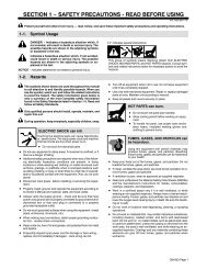
SECTION 1 − SAFETY PRECAUTIONS - READ BEFORE USING<br />
1-1. Symbol Usage<br />
Means Warning! Watch Out! There are possible hazards<br />
with this procedure! The possible hazards are shown in<br />
the adjoining symbols.<br />
Marks a special safety message.<br />
Means “Note”; not safety related.<br />
1-2. Arc Welding Hazards<br />
The symbols shown below are used throughout this manual to<br />
call attention to and identify possible hazards. When you see<br />
the symbol, watch out, and follow the related instructions to<br />
avoid the hazard. The safety information given below is only<br />
a summary of the more complete safety information found in<br />
the Safety Standards listed in Section 1-5. Read and follow all<br />
Safety Standards.<br />
Only qualified persons should install, operate, maintain, and<br />
repair this unit.<br />
During operation, keep everybody, especially children, away.<br />
ELECTRIC SHOCK can kill.<br />
Touching live electrical parts can cause fatal shocks<br />
or severe burns. The electrode and work circuit is<br />
electrically live whenever the output is on. The input<br />
power circuit and machine internal circuits are also<br />
live when power is on. In semiautomatic or automatic wire welding, the<br />
wire, wire reel, drive roll housing, and all metal parts touching the<br />
welding wire are electrically live. Incorrectly installed or improperly<br />
grounded equipment is a hazard.<br />
Do not touch live electrical parts.<br />
Wear dry, hole-free insulating gloves and body protection.<br />
Insulate yourself from work and ground using dry insulating mats<br />
or covers big enough to prevent any physical contact with the work<br />
or ground.<br />
Do not use AC output in damp areas, if movement is confined, or if<br />
there is a danger of falling.<br />
Use AC output ONLY if required for the welding process.<br />
If AC output is required, use remote output control if present on<br />
unit.<br />
Disconnect input power or stop engine before installing or<br />
servicing this equipment. Lockout/tagout input power according to<br />
OSHA 29 CFR 1910.147 (see Safety Standards).<br />
Properly install and ground this equipment according to its<br />
Owner’s Manual and national, state, and local codes.<br />
Always verify the supply ground − check and be sure that input<br />
power cord ground wire is properly connected to ground terminal in<br />
disconnect box or that cord plug is connected to a properly<br />
grounded receptacle outlet.<br />
When making input connections, attach proper grounding conductor<br />
first − double-check connections.<br />
Frequently inspect input power cord for damage or bare wiring −<br />
replace cord immediately if damaged − bare wiring can kill.<br />
Turn off all equipment when not in use.<br />
Do not use worn, damaged, undersized, or poorly spliced cables.<br />
Do not drape cables over your body.<br />
Return To Table Of Contents<br />
som _8/03<br />
This group of symbols means Warning! Watch Out! possible<br />
ELECTRIC SHOCK, MOVING PARTS, and HOT PARTS hazards.<br />
Consult symbols and related instructions below for necessary actions<br />
to avoid the hazards.<br />
If earth grounding of the workpiece is required, ground it directly<br />
with a separate cable.<br />
Do not touch electrode if you are in contact with the work, ground,<br />
or another electrode from a different machine.<br />
Use only well-maintained equipment. Repair or replace damaged<br />
parts at once. Maintain unit according to manual.<br />
Wear a safety harness if working above floor level.<br />
Keep all panels and covers securely in place.<br />
Clamp work cable with good metal-to-metal contact to workpiece<br />
or worktable as near the weld as practical.<br />
Insulate work clamp when not connected to workpiece to prevent<br />
contact with any metal object.<br />
Do not connect more than one electrode or work cable to any<br />
single weld output terminal.<br />
SIGNIFICANT DC VOLTAGE exists after removal of<br />
input power on inverters.<br />
Turn Off inverter, disconnect input power, and discharge input<br />
capacitors according to instructions in Maintenance Section<br />
before touching any parts.<br />
FUMES AND GASES can be hazardous.<br />
Welding produces fumes and gases. Breathing<br />
these fumes and gases can be hazardous to your<br />
health.<br />
Keep your head out of the fumes. Do not breathe the fumes.<br />
If inside, ventilate the area and/or use exhaust at the arc to remove<br />
welding fumes and gases.<br />
If ventilation is poor, use an approved air-supplied respirator.<br />
Read the Material Safety Data Sheets (MSDSs) and the<br />
manufacturer’s instructions for metals, consumables, coatings,<br />
cleaners, and degreasers.<br />
Work in a confined space only if it is well ventilated, or while<br />
wearing an air-supplied respirator. Always have a trained watchperson<br />
nearby. Welding fumes and gases can displace air and<br />
lower the oxygen level causing injury or death. Be sure the breathing<br />
air is safe.<br />
Do not weld in locations near degreasing, cleaning, or spraying operations.<br />
The heat and rays of the arc can react with vapors to form<br />
highly toxic and irritating gases.<br />
Do not weld on coated metals, such as galvanized, lead, or<br />
cadmium plated steel, unless the coating is removed from the weld<br />
area, the area is well ventilated, and if necessary, while wearing an<br />
air-supplied respirator. The coatings and any metals containing<br />
these elements can give off toxic fumes if welded.<br />
OM-303 Page 1
ARC RAYS can burn eyes and skin.<br />
Arc rays from the welding process produce intense<br />
visible and invisible (ultraviolet and infrared) rays<br />
that can burn eyes and skin. Sparks fly off from the<br />
weld.<br />
Wear a welding helmet fitted with a proper shade of filter to protect<br />
your face and eyes when welding or watching (see ANSI Z49.1<br />
and Z87.1 listed in Safety Standards).<br />
Wear approved safety glasses with side shields under your<br />
helmet.<br />
Use protective screens or barriers to protect others from flash and<br />
glare; warn others not to watch the arc.<br />
Wear protective clothing made from durable, flame-resistant material<br />
(leather and wool) and foot protection.<br />
WELDING can cause fire or explosion.<br />
Welding on closed containers, such as tanks,<br />
drums, or pipes, can cause them to blow up. Sparks<br />
can fly off from the welding arc. The flying sparks, hot<br />
workpiece, and hot equipment can cause fires and<br />
burns. Accidental contact of electrode to metal objects can cause<br />
sparks, explosion, overheating, or fire. Check and be sure the area is<br />
safe before doing any welding.<br />
Protect yourself and others from flying sparks and hot metal.<br />
Do not weld where flying sparks can strike flammable material.<br />
Remove all flammables within 35 ft (10.7 m) of the welding arc. If<br />
this is not possible, tightly cover them with approved covers.<br />
Be alert that welding sparks and hot materials from welding can<br />
easily go through small cracks and openings to adjacent areas.<br />
Watch for fire, and keep a fire extinguisher nearby.<br />
Be aware that welding on a ceiling, floor, bulkhead, or partition can<br />
cause fire on the hidden side.<br />
Do not weld on closed containers such as tanks, drums, or pipes,<br />
unless they are properly prepared according to AWS F4.1 (see<br />
Safety Standards).<br />
Connect work cable to the work as close to the welding area as<br />
practical to prevent welding current from traveling long, possibly<br />
unknown paths and causing electric shock and fire hazards.<br />
Do not use welder to thaw frozen pipes.<br />
Remove stick electrode from holder or cut off welding wire at<br />
contact tip when not in use.<br />
Wear oil-free protective garments such as leather gloves, heavy<br />
shirt, cuffless trousers, high shoes, and a cap.<br />
Remove any combustibles, such as a butane lighter or matches,<br />
from your person before doing any welding.<br />
FLYING METAL can injure eyes.<br />
Welding, chipping, wire brushing, and grinding<br />
cause sparks and flying metal. As welds cool,<br />
they can throw off slag.<br />
Wear approved safety glasses with side<br />
shields even under your welding helmet.<br />
OM-303 Page 2 Return To Table Of Contents<br />
BUILDUP OF GAS can injure or kill.<br />
Shut off shielding gas supply when not in use.<br />
Always ventilate confined spaces or use<br />
approved air-supplied respirator.<br />
HOT PARTS can cause severe burns.<br />
Do not touch hot parts bare handed.<br />
Allow cooling period before working on gun or<br />
torch.<br />
MAGNETIC FIELDS can affect pacemakers.<br />
Pacemaker wearers keep away.<br />
Wearers should consult their doctor before<br />
going near arc welding, gouging, or spot<br />
welding operations.<br />
NOISE can damage hearing.<br />
Noise from some processes or equipment can<br />
damage hearing.<br />
Wear approved ear protection if noise level is<br />
high.<br />
CYLINDERS can explode if damaged.<br />
Shielding gas cylinders contain gas under high<br />
pressure. If damaged, a cylinder can explode. Since<br />
gas cylinders are normally part of the welding<br />
process, be sure to treat them carefully.<br />
Protect compressed gas cylinders from excessive heat, mechanical<br />
shocks, slag, open flames, sparks, and arcs.<br />
Install cylinders in an upright position by securing to a stationary<br />
support or cylinder rack to prevent falling or tipping.<br />
Keep cylinders away from any welding or other electrical circuits.<br />
Never drape a welding torch over a gas cylinder.<br />
Never allow a welding electrode to touch any cylinder.<br />
Never weld on a pressurized cylinder − explosion will result.<br />
Use only correct shielding gas cylinders, regulators, hoses, and fittings<br />
designed for the specific application; maintain them and<br />
associated parts in good condition.<br />
Turn face away from valve outlet when opening cylinder valve.<br />
Keep protective cap in place over valve except when cylinder is in<br />
use or connected for use.<br />
Read and follow instructions on compressed gas cylinders,<br />
associated equipment, and CGA publication P-1 listed in Safety<br />
Standards.
1-3. Additional Symbols For Installation, Operation, And Maintenance<br />
FIRE OR EXPLOSION hazard.<br />
Do not install or place unit on, over, or near<br />
combustible surfaces.<br />
Do not install unit near flammables.<br />
Do not overload building wiring − be sure power supply system is<br />
properly sized, rated, and protected to handle this unit.<br />
FALLING UNIT can cause injury.<br />
Use lifting eye to lift unit only, NOT running<br />
gear, gas cylinders, or any other accessories.<br />
Use equipment of adequate capacity to lift and<br />
support unit.<br />
If using lift forks to move unit, be sure forks are<br />
long enough to extend beyond opposite side of<br />
unit.<br />
OVERUSE can cause OVERHEATING<br />
Allow cooling period; follow rated duty cycle.<br />
Reduce current or reduce duty cycle before<br />
starting to weld again.<br />
Do not block or filter airflow to unit.<br />
STATIC (ESD) can damage PC boards.<br />
Put on grounded wrist strap BEFORE handling<br />
boards or parts.<br />
Use proper static-proof bags and boxes to<br />
store, move, or ship PC boards.<br />
MOVING PARTS can cause injury.<br />
Keep away from moving parts.<br />
Keep away from pinch points such as drive<br />
rolls.<br />
WELDING WIRE can cause injury.<br />
Do not press gun trigger until instructed to do<br />
so.<br />
Do not point gun toward any part of the body,<br />
other people, or any metal when threading<br />
welding wire.<br />
1-4. California Proposition 65 Warnings<br />
Welding or cutting equipment produces fumes or gases which<br />
contain chemicals known to the State of California to cause<br />
birth defects and, in some cases, cancer. (California Health &<br />
Safety Code Section 25249.5 et seq.)<br />
Battery posts, terminals and related accessories contain lead<br />
and lead compounds, chemicals known to the State of<br />
California to cause cancer and birth defects or other<br />
reproductive harm. Wash hands after handling.<br />
Return To Table Of Contents<br />
MOVING PARTS can cause injury.<br />
Keep away from moving parts such as fans.<br />
Keep all doors, panels, covers, and guards<br />
closed and securely in place.<br />
H.F. RADIATION can cause interference.<br />
High-frequency (H.F.) can interfere with radio<br />
navigation, safety services, computers, and<br />
communications equipment.<br />
Have only qualified persons familiar with<br />
electronic equipment perform this installation.<br />
The user is responsible for having a qualified electrician promptly<br />
correct any interference problem resulting from the installation.<br />
If notified by the FCC about interference, stop using the<br />
equipment at once.<br />
Have the installation regularly checked and maintained.<br />
Keep high-frequency source doors and panels tightly shut, keep<br />
spark gaps at correct setting, and use grounding and shielding to<br />
minimize the possibility of interference.<br />
ARC WELDING can cause interference.<br />
Electromagnetic energy can interfere with<br />
sensitive electronic equipment such as<br />
computers and computer-driven equipment<br />
such as robots.<br />
Be sure all equipment in the welding area is<br />
electromagnetically compatible.<br />
To reduce possible interference, keep weld cables as short as<br />
possible, close together, and down low, such as on the floor.<br />
Locate welding operation 100 meters from any sensitive electronic<br />
equipment.<br />
Be sure this welding machine is installed and grounded<br />
according to this manual.<br />
If interference still occurs, the user must take extra measures<br />
such as moving the welding machine, using shielded cables,<br />
using line filters, or shielding the work area.<br />
For Gasoline Engines:<br />
Engine exhaust contains chemicals known to the State of<br />
California to cause cancer, birth defects, or other reproductive<br />
harm.<br />
For Diesel Engines:<br />
Diesel engine exhaust and some of its constituents are known<br />
to the State of California to cause cancer, birth defects, and<br />
other reproductive harm.<br />
OM-303 Page 3
1-5. Principal Safety Standards<br />
Safety in Welding, Cutting, and Allied Processes, ANSI Standard Z49.1,<br />
from American Welding Society, 550 N.W. LeJeune Rd, Miami FL 33126<br />
(phone: 305-443-9353, website: www.aws.org).<br />
Recommended Safe Practices for the Preparation for Welding and Cutting<br />
of Containers and Piping, American Welding Society Standard<br />
AWS F4.1, from American Welding Society, 550 N.W. LeJeune Rd, Miami,<br />
FL 33126 (phone: 305-443-9353, website: www.aws.org).<br />
National <strong>Electric</strong>al Code, NFPA Standard 70, from National Fire Protection<br />
Association, P.O. Box 9101, 1 Battery March Park, Quincy, MA<br />
02269−9101 (phone: 617−770−3000, website: www.nfpa.org and www.<br />
sparky.org).<br />
Safe Handling of Compressed Gases in Cylinders, CGA Pamphlet P-1,<br />
from Compressed Gas Association, 1735 Jefferson Davis Highway,<br />
Suite 1004, Arlington, VA 22202−4102 (phone: 703−412−0900, website:<br />
www.cganet.com).<br />
Code for Safety in Welding and Cutting, CSA Standard W117.2, from<br />
Canadian Standards Association, Standards Sales, 178 Rexdale<br />
1-6. EMF Information<br />
Considerations About Welding And The Effects Of Low Frequency<br />
<strong>Electric</strong> And Magnetic Fields<br />
Welding current, as it flows through welding cables, will cause electromagnetic<br />
fields. There has been and still is some concern about such<br />
fields. However, after examining more than 500 studies spanning 17<br />
years of research, a special blue ribbon committee of the National<br />
Research Council concluded that: “The body of evidence, in the<br />
committee’s judgment, has not demonstrated that exposure to powerfrequency<br />
electric and magnetic fields is a human-health hazard.”<br />
However, studies are still going forth and evidence continues to be<br />
examined. Until the final conclusions of the research are reached, you<br />
may wish to minimize your exposure to electromagnetic fields when<br />
welding or cutting.<br />
To reduce magnetic fields in the workplace, use the following<br />
procedures:<br />
OM-303 Page 4 Return To Table Of Contents<br />
Boulevard, Rexdale, Ontario, Canada M9W 1R3 (phone:<br />
800−463−6727 or in Toronto 416−747−4044, website: www.csa−international.org).<br />
Practice For Occupational And Educational Eye And Face Protection,<br />
ANSI Standard Z87.1, from American National Standards Institute, 11<br />
West 42nd Street, New York, NY 10036−8002 (phone: 212−642−4900,<br />
website: www.ansi.org).<br />
Standard for Fire Prevention During Welding, Cutting, and Other Hot<br />
Work, NFPA Standard 51B, from National Fire Protection Association,<br />
P.O. Box 9101, 1 Battery March Park, Quincy, MA 02269−9101 (phone:<br />
617−770−3000, website: www.nfpa.org and www. sparky.org).<br />
OSHA, Occupational Safety and Health Standards for General Industry,<br />
Title 29, Code of Federal Regulations (CFR), Part 1910, Subpart Q,<br />
and Part 1926, Subpart J, from U.S. Government Printing Office, Superintendent<br />
of Documents, P.O. Box 371954, Pittsburgh, PA 15250 (there<br />
are 10 Regional Offices−−phone for Region 5, Chicago, is<br />
312−353−2220, website: www.osha.gov).<br />
1. Keep cables close together by twisting or taping them.<br />
2. Arrange cables to one side and away from the operator.<br />
3. Do not coil or drape cables around your body.<br />
4. Keep welding power source and cables as far away from operator<br />
as practical.<br />
5. Connect work clamp to workpiece as close to the weld as possible.<br />
About Pacemakers:<br />
Pacemaker wearers consult your doctor first. If cleared by your doctor,<br />
then following the above procedures is recommended.
SECTION 2 − CONSIGNES DE SÉCURITÉ − À LIRE AVANT<br />
UTILISATION<br />
2-1. Signification des symboles<br />
Signifie « Mise en garde. Faire preuve de vigilance. »<br />
Cette procédure présente des risques identifiés par les<br />
symboles adjacents aux directives.<br />
Identifie un message de sécurité particulier.<br />
Signifie « NOTA » ; n’est pas relatif à la sécurité.<br />
2-2. Dangers relatifs au soudage à l’arc<br />
Les symboles ci-après sont utilisés tout au long du présent<br />
manuel pour attirer l’attention sur les dangers potentiels et les<br />
identifier. Lorsqu’on voit un symbole, faire preuve de vigilance et<br />
suivre les directives mentionnées afin d’éviter tout danger. Les<br />
consignes de sécurité énoncées ci-après ne font que résumer le<br />
contenu des normes de sécurité mentionnées à la section 2-4.<br />
Lire et respecter toutes ces normes.<br />
L’installation, l’utilisation, l’entretien et les réparations ne doivent<br />
être confiés qu’à des personnes qualifiées.<br />
Pendant l’utilisation de l’appareil, tenir à l’écart toute personne,<br />
en particulier les enfants.<br />
LES DÉCHARGES ÉLECTRIQUES<br />
peuvent être mortelles.<br />
Un simple contact avec des pièces sous tension peut<br />
causer une électrocution ou des blessures graves.<br />
L’électrode et le circuit de soudage sont sous tension<br />
dès que l’appareil est en fonctionnement. Le circuit<br />
d’entrée et les circuits internes de l’appareil sont également sous tension.<br />
En soudage semi−automatique ou automatique, le fil, le dévidoir, le<br />
logement des galets d’entraînement et les pièces métalliques en contact<br />
avec le fil de soudage sont sous tension. Tout matériel mal installé ou mal<br />
mis à la terre présente un danger.<br />
Ne jamais toucher aux pièces électriques sous tension.<br />
Porter des gants et des vêtements de protection secs et exempts de<br />
trous.<br />
S’isoler de la pièce et de la terre au moyen de tapis ou autres dispositifs<br />
isolants suffisamment grands pour empêcher tout contact<br />
physique avec la pièce ou la terre.<br />
Ne pas se servir d’une source de courant alternatif dans les zones humides,<br />
les endroits confinés ou là où on risque de tomber.<br />
Ne se servir d’une source de courant alternatif QUE si le procédé de soudage<br />
l’exige.<br />
Si l’utilisation d’une source de courant alternatif s’avère nécessaire, se servir<br />
de la fonction de télécommande si l’appareil en est équipé.<br />
Couper l’alimentation ou arrêter le moteur avant de procéder à l’installation,<br />
à la réparation ou à l’entretien de l’appareil. Couper/étiqueter<br />
l’alimentation selon la norme OSHA 29 CFR 1910.147 (voir les normes<br />
de sécurité).<br />
Installer et mettre à la terre correctement l’appareil conformément à<br />
son manuel d’utilisation et aux codes nationaux, provinciaux et<br />
municipaux.<br />
Toujours vérifier la terre du cordon d’alimentation − Vérifier et s’assurer<br />
que le fil de terre du cordon d’alimentation est bien raccordé à la<br />
borne de terre du sectionneur ou que la fiche du cordon est raccordée<br />
à une prise correctement mise à la terre.<br />
Pour exécuter les branchements d’entrée, fixer d’abord le conducteur<br />
de mise à la terre adéquat et contre−vérifier les connexions.<br />
Vérifier fréquemment le cordon d’alimentation et s’assurer qu’il n’est<br />
ni endommagé ni dénudé ; le remplacer immédiatement s’il est endommagé<br />
− tout câble dénudé peut causer une électrocution.<br />
Mettre l’appareil hors tension quand on ne l’utilise pas.<br />
Ne pas utiliser de câbles usés, endommagés, de calibre insuffisant ou<br />
mal épissés.<br />
Ne pas s’enrouler les câbles autour du corps.<br />
Si la pièce soudée doit être mise à la terre, le faire directement avec un<br />
câble distinct.<br />
Ne pas toucher l’électrode quand on est en contact avec la pièce, la<br />
terre ou une électrode d’une autre machine.<br />
Revenez à la table des matières<br />
som_fre 8/03<br />
Ce groupe de symboles signifie « Mise en garde. Faire preuve de vigilance.<br />
» Il y a des dangers liés aux CHOCS ÉLECTRIQUES, aux<br />
PIÈCES EN MOUVEMENT et aux PIÈCES CHAUDES. Se reporter<br />
aux symboles et aux directives ci-dessous afin de connaître les mesures<br />
à prendre pour éviter tout danger.<br />
N’utiliser que du matériel en bon état. Réparer ou remplacer sur−le−<br />
champ les pièces endommagées. Entretenir l’appareil conformément<br />
au présent manuel.<br />
Porter un harnais de sécurité quand on travaille en hauteur.<br />
Maintenir solidement en place tous les panneaux et capots.<br />
Fixer le câble de retour de façon à obtenir un bon contact métal sur<br />
métal avec la pièce à souder ou la table de travail, le plus près possible<br />
de la soudure.<br />
Ne pas connecter plus d’une électrode ou plus d’un câble de masse à un<br />
même terminal de sortie.<br />
Il subsiste un COURANT CONTINU IMPORTANT<br />
dans les convertisseurs après la suppression de<br />
l’alimentation électrique.<br />
Arrêter les convertisseurs, débrancher le courant électrique et décharger<br />
les condensateurs d’alimentation selon les instructions<br />
énoncées à la section Entretien avant de toucher les pièces.<br />
LES FUMÉES ET LES GAZ peuvent<br />
être dangereux.<br />
Le soudage génère des fumées et des gaz dont<br />
l’inhalation peut être dangereuse pour la santé.<br />
Se tenir à distance des fumées et ne pas les inhaler.<br />
À l’intérieur, ventiler la zone et/ou utiliser un dispositif d’aspiration au<br />
niveau de l’arc pour l’évacuation des fumées et des gaz de soudage.<br />
Si la ventilation est insuffisante, utiliser un respirateur à adduction<br />
d’air agréé.<br />
Lire les fiches techniques de santé−sécurité (FTSS) et les instructions<br />
du fabricant concernant les métaux, les consommables, les<br />
revêtements, les nettoyants et les dégraisseurs.<br />
Ne travailler dans un espace clos que s’il est bien ventilé ou porter un<br />
respirateur à adduction d’air. Demander toujours à un surveillant dûment<br />
formé de se tenir à proximité. Des fumées et des gaz de soudage<br />
peuvent se substituer à l’air, abaisser la teneur en oxygène et causer<br />
des lésions ou des accidents mortels. S’assurer que l’air est respirable.<br />
Ne pas souder à proximité d’opérations de dégraissage, de nettoyage<br />
ou de pulvérisation. La chaleur et les rayons de l’arc peuvent réagir en<br />
présence de vapeurs et former des gaz hautement toxiques et irritants.<br />
Ne pas souder de métaux munis d’un revêtement, tels que la tôle<br />
d’acier galvanisée, plombée ou cadmiée, à moins que le revêtement<br />
n’ait été enlevé dans la zone de soudage, que l’endroit soit bien ventilé,<br />
et si nécessaire, porter un respirateur à adduction d’air. Les<br />
revêtements et tous les métaux renfermant ces éléments peuvent dégager<br />
des fumées toxiques lorsqu’on les soude.<br />
OM-303 Page 5
LES RAYONS DE L’ARC peuvent causer<br />
des brûlures oculaires et cutanées.<br />
Le rayonnement de l’arc génère des rayons visibles et<br />
invisibles intenses (ultraviolets et infrarouges) susceptibles<br />
de causer des brûlures oculaires et cutanées.<br />
Des étincelles sont projetées pendant le soudage.<br />
Porter un masque de soudage muni d’un filtre de la nuance adéquate<br />
pour se protéger le visage et les yeux pendant le soudage ou pour regarder<br />
(voir les normes de sécurité ANSI Z49.1 et Z87.1).<br />
Porter des lunettes de sécurité à écrans latéraux sous le masque.<br />
Utiliser des écrans ou des barrières pour protéger les tiers de l’éclat<br />
éblouissant ou aveuglant de l’arc ; leur demander de ne pas regarder<br />
l’arc.<br />
Porter des vêtements de protection en matière durable et ignifuge<br />
(cuir ou laine) et des chaussures de sécurité.<br />
LE SOUDAGE peut causer un incendie<br />
ou une explosion.<br />
Le soudage effectué sur des récipients fermés tels que<br />
des réservoirs, des fûts ou des conduites peut causer<br />
leur éclatement. Des étincelles peuvent être projetées<br />
de l’arc de soudure. La projection d’étincelles, les<br />
pièces chaudes et les équipements chauds peuvent causer des<br />
incendies et des brûlures. Le contact accidentel de l’électrode avec tout<br />
objet métallique peut causer des étincelles, une explosion, un surchauffement<br />
ou un incendie. Avant de commencer le soudage, vérifier et<br />
s’assurer que l’endroit ne présente pas de danger.<br />
Se protéger et protéger les tiers de la projection d’étincelles et de métal<br />
chaud.<br />
Ne pas souder à un endroit où des étincelles peuvent tomber sur des<br />
substances inflammables.<br />
Placer toutes les substances inflammables à une distance de 10,7 m<br />
de l’arc de soudage. En cas d’impossibilité, les recouvrir soigneusement<br />
avec des protections agréées.<br />
Des étincelles et des matières en fusion peuvent facilement passer<br />
même par des fissures et des ouvertures de petites dimensions.<br />
Surveiller tout déclenchement d’incendie et tenir un extincteur à proximité.<br />
Le soudage effectué sur un plafond, un plancher, une paroi ou une<br />
cloison peut déclencher un incendie de l’autre côté.<br />
Ne pas souder des récipients fermés tels que des réservoirs, des fûts<br />
ou des conduites, à moins qu’ils n’aient été préparés conformément à<br />
l’AWS F4.1 (voir les normes de sécurité).<br />
Brancher le câble sur la pièce le plus près possible de la zone de soudage<br />
pour éviter que le courant ne circule sur une longue distance, par<br />
des chemins inconnus, et ne cause des risques d’électrocution et d’incendie.<br />
Ne pas utiliser le poste de soudage pour dégeler des conduites gelées.<br />
En cas de non utilisation, enlever la baguette d’électrode du porte−<br />
électrode ou couper le fil au raz du tube−contact.<br />
Porter des vêtements de protection exempts d’huile tels que des<br />
gants en cuir, une chemise en tissu épais, des pantalons sans revers,<br />
des chaussures montantes et un masque.<br />
Avant de souder, retirer tout produit combustible de ses poches, tel<br />
qu’un briquet au butane ou des allumettes.<br />
LES PARTICULES PROJETÉES peuvent<br />
blesser les yeux.<br />
Le soudage, le burinage, le passage de la pièce à<br />
la brosse métallique et le meulage provoquent<br />
l’émission d’étincelles et de particules métalliques.<br />
Pendant leur refroidissement, les soudures risquent de projeter du<br />
laitier.<br />
Porter des lunettes de sécurité à écrans latéraux agréés, même sous le<br />
masque de soudage.<br />
OM-303 Page 6 Revenez à la table des matières<br />
LES ACCUMULATIONS DE GAZ peuvent<br />
causer des blessures ou même<br />
la mort.<br />
Couper l’alimentation en gaz protecteur en cas de<br />
non utilisation.<br />
Veiller toujours à bien ventiler les espaces confinés ou porter un respirateur<br />
à adduction d’air agréé.<br />
LES PIÈCES CHAUDES peuvent causer<br />
des brûlures graves.<br />
Ne pas toucher les pièces chaudes à main nue.<br />
Prévoir une période de refroidissement avant<br />
d’utiliser le pistolet ou la torche.<br />
LES CHAMPS MAGNÉTIQUES peuvent<br />
perturber le fonctionnement des stimulateurs<br />
cardiaques.<br />
Les personnes qui portent un stimulateur cardiaque<br />
doivent se tenir à distance.<br />
Ils doivent consulter leur médecin avant de s’approcher<br />
d’un lieu où on exécute des opérations de soudage<br />
à l’arc, de gougeage ou de soudage par points.<br />
LE BRUIT peut affecter l’ouïe.<br />
Le bruit de certains processus et équipements peut<br />
affecter l’ouïe.<br />
Porter des protecteurs d’oreille agréés si le niveau<br />
sonore est trop élevé.<br />
Les BOUTEILLES endommagées<br />
peuvent exploser.<br />
Les bouteilles de gaz protecteur contiennent du gaz<br />
sous haute pression. Toute bouteille endommagée<br />
peut exploser. Comme les bouteilles de gaz font<br />
normalement partie du procédé de soudage, les<br />
manipuler avec précaution.<br />
Protéger les bouteilles de gaz comprimé de la chaleur excessive, des<br />
chocs mécaniques, du laitier, des flammes nues, des étincelles et des<br />
arcs.<br />
Placer les bouteilles debout en les fixant dans un support stationnaire<br />
ou dans un porte−bouteilles pour les empêcher de tomber ou de se<br />
renverser.<br />
Tenir les bouteilles éloignées des circuits de soudage ou autres circuits<br />
électriques.<br />
Ne jamais poser une torche de soudage sur une bouteille de gaz.<br />
Ne jamais mettre une électrode de soudage en contact avec une bouteille<br />
de gaz.<br />
Ne jamais souder une bouteille contenant du gaz sous pression − elle<br />
risquerait d’exploser.<br />
N’utiliser que les bouteilles de gaz protecteur, régulateurs, tuyaux et<br />
raccords adéquats pour l’application envisagée ; les maintenir en bon<br />
état, ainsi que les pièces connexes.<br />
Détourner la tête lorsqu’on ouvre la soupape d’une bouteille.<br />
Laisser le capuchon protecteur sur la soupape, sauf en cas d’utilisation<br />
ou de branchement de la bouteille<br />
Lire et suivre les instructions concernant les bouteilles de gaz comprimé,<br />
les équipements associés et les publications P−1 de la CGA,<br />
mentionnées dans les normes de sécurité.
2-3. Autres symboles relatifs à l’installation, au fonctionnement et à l’entretien de<br />
l’appareil.<br />
Risque D’INCENDIE OU D’EXPLO-<br />
SION<br />
Ne pas placer l’appareil sur une surface inflammable,<br />
ni au−dessus ou à proximité d’elle.<br />
Ne pas installer l’appareil à proximité de produits inflammables.<br />
Ne pas surcharger l’installation électrique − s’assurer que l’alimentation<br />
est correctement dimensionnée et protégée avant de mettre<br />
l’appareil en service.<br />
LA CHUTE DE L’APPAREIL peut<br />
blesser.<br />
N’utiliser que l’anneau de levage pour lever l’appareil.<br />
NE PAS utiliser le chariot, les bouteilles de<br />
gaz ou tout autre accessoire.<br />
Utiliser un engin de capacité adéquate pour lever<br />
l’appareil.<br />
Si on utilise un chariot élévateur pour déplacer l’unité, s’assurer que<br />
les fourches sont suffisamment longues pour dépasser du côté opposé<br />
de l’appareil.<br />
L’EMPLOI EXCESSIF peut FAIRE<br />
SURCHAUFFER L’ÉQUIPEMENT.<br />
Prévoir une période de refroidissement ; respecter<br />
le cycle opératoire nominal.<br />
Réduire le courant ou le cycle opératoire avant de<br />
reprendre le soudage.<br />
Ne pas obstruer les orifices ou filtrer l’alimentation en air du poste.<br />
LES CHARGES ÉLECTROSTATI-<br />
QUES peuvent endommager les circuits<br />
imprimés.<br />
Mettre un bracelet antistatique AVANT de manipuler<br />
des cartes ou des pièces.<br />
Utiliser des pochettes et des boîtes antistatiques<br />
pour stocker, déplacer ou expédier des cartes de<br />
circuits imprimés.<br />
LES PIÈCES MOBILES peuvent causer<br />
des blessures.<br />
Se tenir à l’écart des pièces mobiles.<br />
Se tenir à l’écart des points de coincement tels<br />
que les dévidoirs.<br />
LES FILS DE SOUDAGE peuvent causer<br />
des blessures.<br />
Ne pas appuyer sur la gâchette avant d’en avoir<br />
reçu l’instruction.<br />
Ne pas diriger le pistolet vers soi, vers d’autres<br />
personnes ou vers toute pièce mécanique en engageant<br />
le fil de soudage.<br />
Revenez à la table des matières<br />
LES ORGANES MOBILES peuvent<br />
causer des blessures.<br />
Se tenir à l’écart des organes mobiles comme les<br />
ventilateurs.<br />
Maintenir fermés et bien fixés les portes,<br />
panneaux, recouvrements et dispositifs de<br />
protection.<br />
LE RAYONNEMENT HAUTE FRÉ-<br />
QUENCE (H. F.) risque de causer des<br />
interférences.<br />
Le rayonnement haute fréquence peut causer<br />
des interférences avec les équipements de radionavigation<br />
et de communication, les services de<br />
sécurité et les ordinateurs.<br />
Ne demander qu’à des personnes qualifiées familiarisées avec les<br />
équipements électroniques de faire fonctionner l’installation.<br />
L’utilisateur est tenu de faire corriger rapidement par un électricien<br />
qualifié les interférences causées par l’installation.<br />
Si la Federal Communications Commission signale des interférences,<br />
arrêter immédiatement l’appareil.<br />
Faire régulièrement contrôler et entretenir l’installation.<br />
Maintenir soigneusement fermés les panneaux et les portes des sources<br />
de haute fréquence, maintenir le jeu d’éclatement au réglage<br />
adéquat et utiliser une terre et un blindage pour réduire les interférences<br />
éventuelles.<br />
LE SOUDAGE À L’ARC peut causer<br />
des interférences.<br />
L’énergie électromagnétique peut causer des<br />
interférences avec l’équipement électronique<br />
sensible tel que les ordinateurs et l’équipement<br />
commandé par ordinateur tel que les robots.<br />
Veiller à ce que tout l’équipement de la zone de soudage soit compatible<br />
au point de vue électromagnétique.<br />
Pour réduire la possibilité d’interférence, maintenir les câbles de soudage<br />
aussi courts que possible, les grouper, et les poser aussi bas<br />
que possible (par ex. : à terre).<br />
Veiller à souder à une distance de 100 mètres de tout équipement<br />
électronique sensible.<br />
Veiller à ce que le poste de soudage soit posé et mis à la terre conformément<br />
au présent manuel.<br />
En cas d’interférences après exécution des directives précédentes, il<br />
incombe à l’utilisateur de prendre des mesures supplémentaires telles<br />
que le déplacement du poste, l’utilisation de câbles blindés,<br />
l’utilisation de filtres de ligne ou la pose de protecteurs dans la zone de<br />
travail.<br />
LES CHAMPS MAGNÉTIQUES peuvent<br />
affecter les stimulateurs cardiaques.<br />
Porteurs de stimulateur cardiaque, restez à distance.<br />
Les porteurs d’un stimulateur cardiaque doivent<br />
d’abord consulter leur médecin avant de s’approcher<br />
des opérations de soudage à l’arc, de gougeage<br />
ou de soudage par points.<br />
OM-303 Page 7
2-4. Principales normes de sécurité<br />
Safety in Welding, Cutting, and Allied Processes, norme ANSI Z49.1,<br />
de l’American Welding Society, 550 N.W. LeJeune Rd, Miami FL 33126<br />
(téléphone : (305) 443−9353, site Web : www.aws.org).<br />
Recommended Safe Practices for the Preparation for Welding and Cutting<br />
of Containers and Piping, norme American Welding Society AWS<br />
F4.1, de l’American Welding Society, 550 N.W. LeJeune Rd, Miami, FL<br />
33126 (téléphone : (305) 443−9353, site Web : www.aws.org).<br />
National <strong>Electric</strong>al Code, norme NFPA 70, de la National Fire Protection<br />
Association, P.O. Box 9101, 1 Battery March Park, Quincy, MA<br />
02269−9101 (téléphone : (617) 770−3000, sites Web : www.nfpa.org et<br />
www.sparky.org).<br />
Safe Handling of Compressed Gases in Cylinders, brochure CGA P−1,<br />
de la Compressed Gas Association, 1735 Jefferson Davis Highway,<br />
Suite 1004, Arlington, VA 22202−4102 (téléphone : (703) 412−0900,<br />
site Web : www.cganet.com).<br />
Code for Safety in Welding and Cutting, norme CSA W117.2, de la Canadian<br />
Standards Association, Standards Sales, 178 boulevard<br />
2-5. Information sur les champs électromagnétiques<br />
Données sur le soudage électrique et les effets des champs magnétiques<br />
basse fréquence sur l’organisme<br />
En parcourant les câbles de soudage, le courant crée des champs électromagnétiques.<br />
Les effets potentiels de tels champs restent<br />
préoccupants. Cependant, après avoir examiné plus de 500 études qui<br />
ont été faites pendant une période de recherche de 17 ans, un comité<br />
de spécialistes du National Research Council a conclu : « L’accumulation<br />
de preuves n’a pas démontré que l’exposition aux champs<br />
magnétiques et aux champs électriques à haute fréquence constitue un<br />
risque pour la santé humaine ». Toutefois, les études et l’examen des<br />
preuves se poursuivent. En attendant les conclusions finales de la recherche,<br />
il serait souhaitable de réduire l’exposition aux champs<br />
électromagnétiques pendant le soudage ou le coupage.<br />
OM-303 Page 8 Revenez à la table des matières<br />
Rexdale, Rexdale (Ontario) Canada M9W 1R3 (téléphone : (800)<br />
463−6727 ou à Toronto : (416) 747−4044, site Web : www.csa−international.org).<br />
Practice For Occupational And Educational Eye And Face Protection,<br />
norme ANSI Z87.1, de l’American National Standards Institute, 11 West<br />
42nd Street, New York, NY 10036−8002 (téléphone : (212) 642−4900,<br />
site Web : www.ansi.org).<br />
Standard for Fire Prevention During Welding, Cutting, and Other Hot<br />
Work, norme NFPA 51B, de la National Fire Protection Association,<br />
P.O. Box 9101, 1 Battery March Park, Quincy, MA 02269−9101 (téléphone<br />
: (617) 770−3000, site Web : www.nfpa.org et www.sparky.org).<br />
OSHA, Occupational Safety and Health Standards for General Industry,<br />
Title 29, Code of Federal Regulations (CFR), Part 1910, Subpart Q,<br />
and Part 1926, Subpart J, de l’U.S. Government Printing Office, Superintendent<br />
of Documents, P.O. Box 371954, Pittsburgh, PA 15250 (il y a<br />
10 bureaux régionaux − Téléphone pour la Région 5, Chicago : (312)<br />
353−2220, site Web : www.osha.gov).<br />
Afin de réduire les champs électromagnétiques en milieu de travail, respecter<br />
les consignes suivantes :<br />
1. Garder les câbles ensemble en les torsadant ou en les fixant avec du<br />
ruban adhésif.<br />
2. Mettre tous les câbles du côté opposé à l’opérateur.<br />
3. Ne pas s’enrouler les câbles autour du corps.<br />
4. Garder le poste de soudage et les câbles le plus loin possible de soi.<br />
5. Placer la pince de masse le plus près possible de la zone de soudage.<br />
Consignes relatives aux stimulateurs cardiaques :<br />
Les personnes qui portent un stimulateur cardiaque doivent avant tout<br />
consulter leur médecin. Si ce dernier les déclare aptes, il leur est recommandé<br />
de respecter les consignes ci-dessus.
3-1. General Precautionary Label<br />
SECTION 3 − DEFINITIONS<br />
Return To Table Of Contents<br />
OM-303 Page 9
3-2. Symbols And Definitions<br />
Tig Welding<br />
Remote Foot/Hand<br />
Control<br />
OM-303 Page 10 Return To Table Of Contents<br />
Stick Welding High Temperature<br />
Output Alternating Current Direct Current On<br />
Electrode Positive<br />
Electrode<br />
Negative<br />
Do Not Switch<br />
Under Load<br />
Voltage Input<br />
A Amperes Off Electrode Gas Out<br />
U 0<br />
Amperage Control/<br />
Panel<br />
Rated No Load<br />
Voltage (Average) U 2<br />
I 1max Rated Maximum<br />
Supply Current I 2<br />
Percent U 1<br />
4-1. Included with Your Unit<br />
4<br />
6<br />
5<br />
3<br />
8<br />
Work Remote V Volts<br />
Conventional Load<br />
Voltage X Duty Cycle I 1eff<br />
Rated Welding<br />
Current IP<br />
Degree Of<br />
Protection<br />
11<br />
1<br />
Maximum Effective<br />
Supply Current<br />
Single-Phase<br />
Combined AC/DC<br />
Power Source<br />
Primary Voltage Line Connection Hz Hertz<br />
SECTION 4 − INTRODUCTION<br />
1<br />
2<br />
7<br />
1 12 ft (3.7 m) Work Cable<br />
and Clamp<br />
2 150 Amp TIG Torch with<br />
12-1/2 ft (3.8 m) Cord and<br />
Flow-Through<br />
Quick-Connect (50 Hz<br />
models come with 25 ft (7.6<br />
m) TIG Torch)<br />
3 Electrode Holder and<br />
Quick-Connect<br />
4 Gas Hose<br />
5 Gas Regulator (Not<br />
included with 50 Hz<br />
models)<br />
6 “How-To” DVD<br />
7 RFC-14 Foot Control with<br />
20 ft (6 m) Cord (60 Hz<br />
models only. 50 Hz models<br />
come with RCC-14<br />
fingertip control instead.)<br />
8 8 ft (2.4 m) Primary Cord<br />
(Plug supplied with 230<br />
Volt model only)<br />
Some assembly is required.<br />
For options and accessories see<br />
back of book or contact your distributor.
4-2. Specifications<br />
A. 60 Hertz Models<br />
Rated Output at 20%<br />
Duty Cycle<br />
TIG: 150 A at 15 VDC<br />
(GTAW) 150 A at 15 VAC<br />
Stick: 130 A at 25 VDC<br />
(SMAW) 150 A at 25 VAC<br />
* () While idling.<br />
B. 50 Hertz Models<br />
Rated Output at 20%<br />
Duty Cycle<br />
TIG: 150 A at 15 VDC<br />
(GTAW) 150 A at 15 VAC<br />
Stick: 130 A at 25 VDC<br />
(SMAW) 150 A at 25 VAC<br />
* () While idling.<br />
4-3. Duty Cycle Chart<br />
4-4. Volt-Ampere Curves<br />
Welding Amperage Range<br />
AC High AC Low DC<br />
TIG Welding A Range<br />
50−165 20−50 30−160<br />
Stick Welding A Range<br />
35−165 20−50 25−130<br />
Welding Amperage Range<br />
AC High AC Low DC<br />
TIG Welding A Range<br />
50−165 20−50 30−160<br />
Stick Welding A Range<br />
35−165 20−50 25−130<br />
Max.<br />
Open-Circuit<br />
Voltage Rated Output KVA Dimensions<br />
78 200 V−60 A (3.6)*<br />
78<br />
Return To Table Of Contents<br />
230V−52 A (3.0)*<br />
460 V−33 A (1.5)*<br />
12.0<br />
(0.64)*<br />
H: 18 in (457 mm)<br />
W: 13 in (330 mm)<br />
D: 25 1 / 2 in (648 mm)<br />
Max.<br />
Open-Circuit<br />
Voltage Rated Output KVA Dimensions<br />
78 380 V−39 A (2.0)* 14.8 H: 18 in (457 mm)<br />
415V−36 A (1.5)*<br />
(0.64)*<br />
W: 13 in (330 mm)<br />
78<br />
D: 251 / 2 in (648 mm)<br />
GTAW: 20% Duty Cycle at 150 A AC/DC<br />
SMAW: 20% Duty Cycle at 130 A DC, or<br />
150 A AC<br />
2 Minutes<br />
Welding<br />
8 Minutes<br />
Resting<br />
Net<br />
Weight<br />
140 lb<br />
(64 kg)<br />
Net<br />
Weight<br />
140 lb<br />
(64 kg)<br />
Duty cycle is percentage of 10<br />
minutes that unit can weld at rated<br />
load without overheating.<br />
Exceeding duty cycle can<br />
damage<br />
warranty.<br />
unit and void<br />
ST-157 648-A<br />
Volt-ampere curves show minimum<br />
and maximum voltage and amperage<br />
output capabilities of welding<br />
power source. Curves of other settings<br />
fall between curves shown.<br />
ssb1.1 10/91 − ST-157 625-B / ST-157 626-B<br />
OM-303 Page 11
5-1. Selecting a Location<br />
18 in<br />
(460 mm)<br />
5-2. Typical Stick Connections<br />
1<br />
SECTION 5 − INSTALLATION<br />
18 in<br />
(460 mm)<br />
18 in<br />
(460 mm)<br />
OM-303 Page 12 Return To Table Of Contents<br />
2<br />
Position unit so air can circulate.<br />
For information about sources of<br />
high-frequency see Section 9.<br />
For carts and caster kits see back<br />
of book or contact your distributor.<br />
ST-158 075<br />
Turn Off power before making<br />
connections.<br />
1 Electrode Holder<br />
2 Work Clamp<br />
Connect to receptacle as shown.<br />
ST-157 858-A
5-3. Typical TIG Connections<br />
2<br />
1<br />
Tools Needed:<br />
5/8, 1-1/8 in<br />
7<br />
3<br />
6<br />
Return To Table Of Contents<br />
5<br />
Turn Off power before making<br />
connections.<br />
1 Remote Control<br />
2 Torch<br />
Connect to receptacles as shown.<br />
3 Work Clamp<br />
4 Cylinder<br />
Chain or secure cylinder to running<br />
gear, wall, or other stationary<br />
support.<br />
5 Cylinder Valve<br />
Open valve slightly so gas flow<br />
blows dirt from valve. Close valve.<br />
6 Regulator/Flow Gauge<br />
Install so face is vertical.<br />
7 Flow Adjust<br />
Typical flow rate is 20 cfh (cubic feet<br />
per hour) (9.4 L/min).<br />
4<br />
Ref. ST-157 858-A<br />
OM-303 Page 13
5-4. <strong>Electric</strong>al Service Guide S-0092J<br />
For 230 V models with wall receptacle, 100% duty cycle used to calculate data below. 20% duty cycle used for all other models.<br />
Input Voltage 200 230 380 415 460<br />
Input Amperes at Rated Output 59 52 39 36 33<br />
Standard Fuse or Circuit Breaker Rating<br />
(Max. Recommended)<br />
OM-303 Page 14 Return To Table Of Contents<br />
90 Amps 80 Amps 60 Amps 50 Amps 40 Amps<br />
Input Conductor Size (Min.) 10 AWG 6 AWG 12 AWG 12 AWG 14 AWG<br />
Input Conductor Length (Max. Recommended) 42 ft (13 m) 135 ft (41 m) 151 ft (46 m) 181 ft (55 m) 85 ft (26 m)<br />
Grounding Conductor Size (Min.) 10 AWG 8 AWG 12 AWG 12 AWG 14 AWG<br />
Reference: 1996 National <strong>Electric</strong>al Code (NEC).<br />
5-5. Connecting Input Power<br />
Tools Needed:<br />
When making connections in the line<br />
disconnect device, connect the Green Or<br />
Green/Yellow ground conductor first.<br />
All Other<br />
Models<br />
L1<br />
L2<br />
GND/PE<br />
Install conductors into<br />
a deenergized line disconnect<br />
device.<br />
230 Volt<br />
Models Only<br />
L1<br />
Have only qualified persons<br />
make this installation.<br />
Disconnect and lockout/tagout<br />
input power before connecting<br />
input conductors for<br />
wall receptacle or from unit.<br />
Special installation may be<br />
required where gasoline or<br />
volatile liquids are present −<br />
see NEC Article 511 or CEC<br />
Section 20.<br />
230 Volt Models:<br />
Units come equipped with input<br />
power cord and plug. Wall receptacle<br />
is customer supplied. To<br />
install, select type and size input<br />
and grounding conductors using<br />
Section 5-4. Conductor rating must<br />
comply with national, state, and<br />
local electrical codes.<br />
Install and connect grounding conductor<br />
and input conductors in conduit<br />
or equivalent between wall<br />
receptacle and deenergized line<br />
disconnect device.<br />
All Other Models:<br />
Units come equipped with input<br />
power cord for installation into line<br />
disconnect device. Select type and<br />
size overcurrent protection using<br />
Section 5-4.<br />
L2<br />
230 VAC,<br />
1<br />
GND/PE<br />
ST-161 454-A
6-1. Controls<br />
1<br />
8<br />
7<br />
6<br />
1 Weld Process Switch<br />
Use switch to select weld process.<br />
In Stick position (down), weld output goes On<br />
and Off with Power switch.<br />
In GTAW (TIG) position (up), remote control<br />
device turns on and adjusts weld output of unit<br />
as limited by Amperage control. Built-in arc<br />
starter comes on when needed to start or stabilize<br />
welding arc. No adjustments needed for<br />
arc starter.<br />
2 Pilot Light<br />
3 Power Switch<br />
Use switch to turn unit, fan, and pilot light On<br />
and Off.<br />
4 Amperage Control<br />
SECTION 6 − OPERATION<br />
For Stick (SMAW), use control to adjust amperage<br />
within range selected by the Range/Polarity<br />
Switch.<br />
5 Stick (SMAW) Table<br />
Use table to find approximate Stick amperage<br />
output at Amperage control setting.<br />
See Section 6-2 for example of front panel amperage<br />
control.<br />
For remote amperage control used when TIG<br />
(GTAW) welding, front panel Amperage control<br />
setting is the maximum amperage percentage<br />
available at the remote control device.<br />
See Section 6-3 for example of remote amperage<br />
control.<br />
6 Range/Polarity Switch<br />
Use switch to select range and polarity of weld<br />
output.<br />
Return To Table Of Contents<br />
2<br />
3<br />
4<br />
Ref. ST-155 790-F<br />
For Direct Current Electrode Negative<br />
(DCEN), use Electrode Negative position.<br />
For Direct Current Electrode Positive (DCEP),<br />
use Electrode Positive position.<br />
For alternating current (AC), use range needed<br />
for welding application − AC Low or AC High<br />
position − see Warning.<br />
See Section 6-4 to find suggested type of weld<br />
output for application.<br />
7 High Temperature Shutdown Light<br />
Lights when unit overheats and shuts down<br />
(see Section 7-2).<br />
8 Output On (Contactor) Light<br />
Lights when output (contactor) and unit power<br />
are on.<br />
5<br />
OM-303 Page 15
6-2. Example of Front Panel Amperage Control<br />
Select weld process. Select range and polarity.<br />
6-3. Example of Remote Amperage Control<br />
Select weld process.<br />
or<br />
Connect remote control.<br />
Select range and polarity.<br />
Select percentage.<br />
OM-303 Page 16 Return To Table Of Contents<br />
GTAW Welding Amperage Range<br />
AC Low AC High DC<br />
20-50 A 60-165 A 30-165 A<br />
In Example:<br />
Range = DCEN<br />
Percentage of Range = 50%<br />
Remote weld amperage = 30−98 A DC<br />
(50% of 30−165 A DC)<br />
In Example:<br />
Range = DC<br />
Percentage of Range = 50%<br />
Weld Amperage = 33 A DC<br />
Select percentage.
6-4. Process and Material Thickness Guide Label<br />
Aluminum<br />
AC<br />
Guideline For Welding Process And Output For Material<br />
Material Thickness<br />
Material And<br />
Weld Output<br />
22 ga<br />
0.033 in<br />
0.8 mm<br />
20 ga<br />
0.036 in<br />
0.9 mm<br />
18 ga<br />
0.048 in<br />
1.2 mm<br />
16 ga<br />
0.06 in<br />
1.5 mm<br />
14 ga<br />
0.07 in<br />
1.8 mm<br />
12 ga<br />
0.1 in<br />
2.5 mm<br />
11 ga<br />
0.125 in<br />
3.2 mm<br />
10 ga<br />
0.14 in<br />
3.6 mm<br />
6 ga<br />
0.186 in<br />
4.8 mm<br />
2 ga<br />
0.25 in<br />
6.3 mm<br />
−<br />
0.25+ in<br />
6.3+ mm<br />
Steel Or Stainless Steel<br />
SMAW<br />
( )<br />
DCEN<br />
ELECTRODE<br />
NEGATIVE<br />
GTAW<br />
GTAW<br />
With DCEP<br />
Output<br />
Difficult<br />
Return To Table Of Contents<br />
Recommended<br />
GTAW<br />
Not<br />
Recommended<br />
S-167 338<br />
OM-303 Page 17
SECTION 7 − MAINTENANCE AND TROUBLESHOOTING<br />
7-1. Routine Maintenance<br />
3 Months<br />
Disconnect power before maintaining.<br />
Maintain more often during severe conditions.<br />
Replace unreadable labels. Clean and tighten weld terminals.<br />
Repair or replace cracked weld<br />
cable.<br />
Replace o-ring in Electrode/Gas<br />
Output receptacle if cracked.<br />
6 Months<br />
Blow out or vacuum inside.<br />
7-2. Troubleshooting<br />
OM-303 Page 18 Return To Table Of Contents<br />
Or<br />
Repair or replace cracked gas<br />
hose.<br />
Trouble Remedy<br />
No weld output; fan does not run. Place line disconnect switch in On position (see Section 5-5).<br />
Check and replace line fuse(s), if necessary, or reset circuit breaker (see Section 5-5).<br />
Check for proper input power connections (see Section 5-5).<br />
No weld output; fan on. Be sure Range/Polarity switch is not set between positions.<br />
Fan not operating; weld output<br />
available.<br />
Tighten remote control connection to Remote 14 receptacle.<br />
Check remote control (see remote control Owner’s Manual).<br />
Unit overheated. Allow unit to cool (see Section 4-3).<br />
Check for and remove anything blocking fan movement.<br />
Have Factory Authorized Service Agent check fan motor.
SECTION 8 − ELECTRICAL DIAGRAMS<br />
Figure 8-1. Circuit Diagram<br />
Return To Table Of Contents<br />
SB-154 141-C<br />
OM-303 Page 19
SECTION 9 − HIGH FREQUENCY<br />
9-1. Welding Processes Requiring High Frequency<br />
9-2. Incorrect Installation<br />
13<br />
Sources of Direct High-Frequency<br />
Radiation<br />
1 High-Frequency Source (welding power<br />
source with built-in HF or separate HF<br />
unit)<br />
2 Weld Cables<br />
3 Torch<br />
4 Work Clamp<br />
5 Workpiece<br />
6 Work Table<br />
50 ft<br />
(15 m)<br />
Work<br />
OM-303 Page 20 Return To Table Of Contents<br />
1<br />
9<br />
8<br />
7<br />
10<br />
Weld Zone<br />
2<br />
11, 12<br />
Sources of Conduction of High<br />
Frequency<br />
7 Input Power Cable<br />
8 Line Disconnect Device<br />
9 Input Supply Wiring<br />
3<br />
4 5 6<br />
TIG<br />
1<br />
1 High-Frequency Voltage<br />
Helps arc jump air gap between<br />
torch and workpiece and/or<br />
stabilize the arc.<br />
high_freq1 11/96 − S-0693<br />
14<br />
Sources of Reradiation of High<br />
Frequency<br />
10 Ungrounded Metal Objects<br />
11 Lighting<br />
12 Wiring<br />
13 Water Pipes and Fixtures<br />
14 External Phone and Power Lines<br />
S-0694
9-3. Correct Installation<br />
8<br />
6<br />
3 50 ft<br />
(15 m)<br />
1 High-Frequency Source (welding power<br />
source with built-in HF or separate HF<br />
unit)<br />
Ground metal machine case, work output<br />
terminal, line disconnect device, input supply,<br />
and worktable.<br />
2 Center Point of Welding Zone<br />
Midpoint between high-frequency source and<br />
welding torch.<br />
3 Welding Zone<br />
A circle 50 ft (15 m) from center point in all<br />
directions.<br />
4 Weld Output Cables<br />
Keep cables short and close together.<br />
1<br />
Ground all metal objects<br />
and all wiring in<br />
welding zone using<br />
#12 AWG wire.<br />
Nonmetal<br />
Building<br />
Weld Zone<br />
4<br />
2<br />
Ground<br />
workpiece<br />
if required<br />
by codes.<br />
8<br />
11<br />
50 ft<br />
(15 m)<br />
5 Conduit Joint Bonding and Grounding<br />
<strong>Electric</strong>ally join (bond) all conduit sections<br />
using copper straps or braided wire. Ground<br />
conduit every 50 ft (15 m).<br />
6 Water Pipes and Fixtures<br />
Ground water pipes every 50 ft (15 m).<br />
7 External Power or Telephone Lines<br />
Locate high-frequency source at least 50 ft<br />
(15 m) away from power and phone lines.<br />
8 Grounding Rod<br />
Consult the National <strong>Electric</strong>al Code for specifications.<br />
Return To Table Of Contents<br />
5<br />
8<br />
Metal Building<br />
10<br />
7<br />
8<br />
Ref. S-0695 / Ref. S-0695<br />
Metal Building Requirements<br />
9 Metal Building Panel Bonding Methods<br />
Bolt or weld building panels together, install<br />
copper straps or braided wire across seams,<br />
and ground frame.<br />
10 Windows and Doorways<br />
Cover all windows and doorways with<br />
grounded copper screen of not more than 1/4<br />
in (6.4 mm) mesh.<br />
11 Overhead Door Track<br />
Ground the track.<br />
9<br />
OM-303 Page 21
Hardware is common and<br />
not available unless listed.<br />
3<br />
11<br />
2<br />
10<br />
12 13<br />
9<br />
1<br />
SECTION 10 − PARTS LIST<br />
8<br />
6<br />
OM−303 Page 22 Return To Table Of Contents<br />
7<br />
4 5<br />
14<br />
15<br />
16<br />
44<br />
45<br />
17<br />
22<br />
23<br />
29<br />
43<br />
11<br />
18<br />
24<br />
25<br />
28<br />
30<br />
26<br />
41<br />
19<br />
27<br />
Figure 10-1.Main Assembly<br />
20<br />
42<br />
7<br />
40<br />
32<br />
39<br />
31<br />
33<br />
38<br />
34<br />
21<br />
37<br />
48<br />
47<br />
35<br />
34<br />
32<br />
36<br />
46<br />
ST-801 399-C
Item<br />
No.<br />
Dia.<br />
Mkgs.<br />
Part<br />
No.<br />
Description<br />
Figure 10-1. Main Assembly<br />
Return To Table Of Contents<br />
Quantity<br />
. . . 1 . . . . . . . . . . . . . 154 335 . . BEZEL, front . . . . . . . . . . . . . . . . . . . . . . . . . . . . . . . . . . . . . . . . . . . . . . . . . . . . 1<br />
. . . 2 . . . . . . . . . . . . . 203 990 . . LABEL, warning general precautionary . . . . . . . . . . . . . . . . . . . . . . . . . . . . . 1<br />
. . . 3 . . . . . . . . . . . . +165 986 . . WRAPPER, . . . . . . . . . . . . . . . . . . . . . . . . . . . . . . . . . . . . . . . . . . . . . . . . . . . . 1<br />
. . . 4 . . . . PC1 . . . 183 876 . . CIRCUIT CARD, arc start/control (200, 230, 460V models) (consisting of) 1<br />
. . . 4 . . . . PC1 . . . 186 172 . . CIRCUIT CARD, arc start/control (380, 415V models) (consisting of) . . . 1<br />
. . . . . . . . . . . F1 . . . . *012 658 . . . . FUSE, mintr gl slo-blo 2A . . . . . . . . . . . . . . . . . . . . . . . . . . . . . . . . . . . . . . . 1<br />
. . . . . . . . . PLG1,6 . . 130 203 . . CONNECTOR & SOCKETS . . . . . . . . . . . . . . . . . . . . . . . . . . . . . . . . . . . . . . 2<br />
. . . 5 . . . . . . . . . . . . . 134 201 . . STAND-OFF SUPPORT, PC card .312/.375 . . . . . . . . . . . . . . . . . . . . . . . . . 4<br />
. . . 6 . . . . . . . . . . . . . 155 404 . . BRACKET, mtg components . . . . . . . . . . . . . . . . . . . . . . . . . . . . . . . . . . . . . . 1<br />
. . . 7 . . . . . . . . . . . . . 603 106 . . HOSE, nprn brd No. 1 (order by ft) . . . . . . . . . . . . . . . . . . . . . . . . . . . . . . . . . 3ft<br />
. . . 8 . . . . . . . . . . . . . 089 120 . . CLAMP, hose .430-.515 clp dia . . . . . . . . . . . . . . . . . . . . . . . . . . . . . . . . . . . . 2<br />
. . . 9 . . . . GS1 . . . 125 785 . . VALVE, 24VAC 2 way custom port 1/8 orf . . . . . . . . . . . . . . . . . . . . . . . . . . . 1<br />
. . . 10 . . . . . . . . . . . . . 605 227 . . NUT, nylon hex jam .750NPST . . . . . . . . . . . . . . . . . . . . . . . . . . . . . . . . . . . . 1<br />
. . . 11 . . . . . . . . . . . . . 147 571 . . HANDLE . . . . . . . . . . . . . . . . . . . . . . . . . . . . . . . . . . . . . . . . . . . . . . . . . . . . . . . 2<br />
. . . 12 . . . . . . . . . . . . . 155 399 . . PANEL, rear . . . . . . . . . . . . . . . . . . . . . . . . . . . . . . . . . . . . . . . . . . . . . . . . . . . . 1<br />
. . . 13 . . . . . . . . . . . . . 071 906 . . CORD SET, 8-10ga 3/c (200, 380, 460V model) . . . . . . . . . . . . . . . . . . . . . 1<br />
. . . 13 . . . PLG12 . . 047 721 . . CORD SET, 250V 6-50P 8-10ga 3/c (230V model) . . . . . . . . . . . . . . . . . . . 1<br />
. . . 13 . . . . . . . . . . . . . 605 077 . . CABLE, port No. 10 3/c (380, 415, 460V Model) (order by ft) . . . . . . . . . . 8ft<br />
. . . 14 . . . . . . . . . . . . . 604 102 . . CONNECTOR, clamp cable 1.000 . . . . . . . . . . . . . . . . . . . . . . . . . . . . . . . . . 1<br />
. . . 15 . . . . SR1 . . . 193 317 . . RECTIFIER . . . . . . . . . . . . . . . . . . . . . . . . . . . . . . . . . . . . . . . . . . . . . . . . . . . . 1<br />
. . . 16 . . . VR1,R2 . . 044 482 . . SUPPRESSOR . . . . . . . . . . . . . . . . . . . . . . . . . . . . . . . . . . . . . . . . . . . . . . . . . 1<br />
. . . 17 . . . . . . . . . . . . . 150 783 . . BLADE, fan 9 in .312 hub . . . . . . . . . . . . . . . . . . . . . . . . . . . . . . . . . . . . . . . . . 1<br />
. . . 18 . . . . . FM . . . . 188 706 . . MOTOR, fan 230V 1550RPM .312dia shaft . . . . . . . . . . . . . . . . . . . . . . . . . 1<br />
. . . 19 . . . . . . . . . . . . . 203 598 . . BRACKET, mtg fan & rectifier . . . . . . . . . . . . . . . . . . . . . . . . . . . . . . . . . . . . . 1<br />
. . . 20 . . . . . Z1 . . . . 193 871 . . STABILIZER . . . . . . . . . . . . . . . . . . . . . . . . . . . . . . . . . . . . . . . . . . . . . . . . . . . . 1<br />
. . . 21 . . . . . T1 . . . . 193 869 . . TRANSFORMER, pwr main 200V (consisting of) . . . . . . . . . . . . . . . . . . . . 1<br />
. . . 21 . . . . . T1 . . . . 193 873 . . TRANSFORMER, pwr main 230V (consisting of) . . . . . . . . . . . . . . . . . . . . 1<br />
. . . 21 . . . . . T1 . . . . 193 874 . . TRANSFORMER, pwr main 460V (consisting of) . . . . . . . . . . . . . . . . . . . . 1<br />
. . . 21 . . . . . T1 . . . . 193 875 . . TRANSFORMER, pwr main 380V (consisting of) . . . . . . . . . . . . . . . . . . . . 1<br />
. . . 21 . . . . . T1 . . . . 193 877 . . TRANSFORMER, pwr main 415V (consisting of) . . . . . . . . . . . . . . . . . . . . 1<br />
. . . . . . . . . . TP1,2 . . 176 170 . . . . THERMOSTAT, NC . . . . . . . . . . . . . . . . . . . . . . . . . . . . . . . . . . . . . . . . . . . . 2<br />
. . . 22 . . . . . . . . . . . . . 083 147 . . GROMMET, screw No. 8/10 panel hole .312sq .500 high . . . . . . . . . . . . . 4<br />
. . . 23 . . . . . W . . . . 188 009 . . CONTACTOR . . . . . . . . . . . . . . . . . . . . . . . . . . . . . . . . . . . . . . . . . . . . . . . . . . . 1<br />
. . . 24 . . . . . C2 . . . . 155 501 . . CAPACITOR . . . . . . . . . . . . . . . . . . . . . . . . . . . . . . . . . . . . . . . . . . . . . . . . . . . . 1<br />
. . . 25 . . . . . C1 . . . . 155 290 . . CAPACITOR . . . . . . . . . . . . . . . . . . . . . . . . . . . . . . . . . . . . . . . . . . . . . . . . . . . . 1<br />
. . . 26 . . . . . T2 . . . . 188 061 . . TRANSFORMER, impulse HV . . . . . . . . . . . . . . . . . . . . . . . . . . . . . . . . . . . . 1<br />
. . . 27 . . . . . Z2 . . . . 155 499 . . TRANSFORMER, blocking (consisting of) . . . . . . . . . . . . . . . . . . . . . . . . . . 1<br />
. . . 28 . . . . . . . . . . . . . 159 102 . . . . PLATE, mtg block transformer . . . . . . . . . . . . . . . . . . . . . . . . . . . . . . . . . . . 1<br />
. . . 29 . . . . . . . . . . . . . 155 288 . . . . COIL, blocking . . . . . . . . . . . . . . . . . . . . . . . . . . . . . . . . . . . . . . . . . . . . . . . . 1<br />
. . . 30 . . . . . S1 . . . . . 124 511 . . SWITCH, tgl DPST 40A 600VAC . . . . . . . . . . . . . . . . . . . . . . . . . . . . . . . . . . 1<br />
. . . 31 . . . . . . . . . . . . . 165 987 . . BASE . . . . . . . . . . . . . . . . . . . . . . . . . . . . . . . . . . . . . . . . . . . . . . . . . . . . . . . . . . 1<br />
. . . 32 . . . . Elec . . . 186 092 . . RECEPTACLE KIT, dinse . . . . . . . . . . . . . . . . . . . . . . . . . . . . . . . . . . . . . . . . . 1<br />
. . . 33 . . . . . R1 . . . . 035 897 . . POTENTIOMETER, C sltd 1T 2W 1K ohm . . . . . . . . . . . . . . . . . . . . . . . . . . 1<br />
. . . 34 . . . . . . . . . . . . . 134 900 . . STRAIN RELIEF, cable flex .270-.480 cable . . . . . . . . . . . . . . . . . . . . . . . . . 1<br />
. . . 35 . . . . RC1 . . . 143 976 . . CONNECTOR w/SOCKETS . . . . . . . . . . . . . . . . . . . . . . . . . . . . . . . . . . . . . . 1<br />
. . . 36 . . . . . . . . . . . . . 097 924 . . KNOB, pointer . . . . . . . . . . . . . . . . . . . . . . . . . . . . . . . . . . . . . . . . . . . . . . . . . . 1<br />
. . . 37 . . . . . PL3 . . . 155 500 . . LIGHT, indicator . . . . . . . . . . . . . . . . . . . . . . . . . . . . . . . . . . . . . . . . . . . . . . . . . 1<br />
. . . 38 . . . . . . . . . . . . . 148 956 . . HANDLE, switch . . . . . . . . . . . . . . . . . . . . . . . . . . . . . . . . . . . . . . . . . . . . . . . . 1<br />
. . . 39 . . . . . PL2 . . . 157 957 . . LIGHT, ind blu lens 28V snap mtg . . . . . . . . . . . . . . . . . . . . . . . . . . . . . . . . . 1<br />
. . . 40 . . . . . S3 . . . . 155 013 . . SWITCH, rocker SPST 10A 250VAC . . . . . . . . . . . . . . . . . . . . . . . . . . . . . . . 1<br />
. . . 41 . . . . . . . . . . . . . . . . . . . . . . . . NAMEPLATE, (order by model and serial number) . . . . . . . . . . . . . . . . . . .<br />
1<br />
OM-303 Page 23
Item<br />
No.<br />
Dia.<br />
Mkgs.<br />
Part<br />
No.<br />
Description<br />
Figure Figure 10-1. Main Assembly (Continued)<br />
OM−303 Page 24 Return To Table Of Contents<br />
Quantity<br />
. . . 42 . . . . . PL1 . . . 157 958 . . LIGHT, ind wht lens 28V . . . . . . . . . . . . . . . . . . . . . . . . . . . . . . . . . . . . . . . . . . 1<br />
. . . 43 . . . . . . . . . . . . . 155 422 . . PANEL, front . . . . . . . . . . . . . . . . . . . . . . . . . . . . . . . . . . . . . . . . . . . . . . . . . . . 1<br />
. . . 44 . . . . . S2 . . . . 154 896 . . SWITCH, polarity (consisting of) . . . . . . . . . . . . . . . . . . . . . . . . . . . . . . . . . . . 1<br />
. . . 45 . . . . . S4 . . . . 089 645 . . . . SWITCH, lim 11A 125V roller lever actr . . . . . . . . . . . . . . . . . . . . . . . . . . . 1<br />
. . . 46 . . . . . . . . . . . . . 177 359 . . CABLE, work assembly (consisting of) . . . . . . . . . . . . . . . . . . . . . . . . . . . . . 1<br />
. . . 47 . . . . . . . . . . . . . 010 368 . . . . CLAMP, work 200A . . . . . . . . . . . . . . . . . . . . . . . . . . . . . . . . . . . . . . . . . . . . 1<br />
. . . 48 . . . . . . . . . . . . . 026 843 . . . . INSULATOR, vinyl black . . . . . . . . . . . . . . . . . . . . . . . . . . . . . . . . . . . . . . . . 2<br />
. . . . . . . . . . . . . . . . . . . 198 317 . . HOSE, gas 12 ft rubber . . . . . . . . . . . . . . . . . . . . . . . . . . . . . . . . . . . . . . . . . . 1<br />
. . . . . . . . . . . . . . . . . . . 192 121 . . REGULATOR/FLOWMETER, 10−50 cfh argon/co2 . . . . . . . . . . . . . . . . . . 1<br />
. . . . . . . . . . . . . . . . . . . 176 840 . . ELECTRODE HOLDER/CABLE, (consisting of) . . . . . . . . . . . . . . . . . . . . . 1<br />
. . . . . . . . . . . . . . . . . . . 134 460 . . . . CONNECTOR, twlk insul male . . . . . . . . . . . . . . . . . . . . . . . . . . . . . . . . . . 1<br />
+When ordering a component originally displaying a precautionary label, the label should also be ordered.<br />
*Recommended Spare Parts.<br />
To maintain the factory original performance of your equipment, use only Manufacturer’s Suggested<br />
Replacement Parts. Model and serial number required when ordering parts from your local distributor.
Warranty Questions?<br />
Call<br />
1-800-4-A-MILLER<br />
for your local<br />
<strong>Miller</strong> distributor.<br />
Your distributor also gives<br />
you ...<br />
Service<br />
You always get the fast,<br />
reliable response you<br />
need. Most replacement<br />
parts can be in your<br />
hands in 24 hours.<br />
Support<br />
Need fast answers to the<br />
tough welding questions?<br />
Contact your distributor.<br />
The expertise of the<br />
distributor and <strong>Miller</strong> is<br />
there to help you, every<br />
step of the way.<br />
Effective January 1, 2003<br />
(Equipment with a serial number preface of “LC” or newer)<br />
This limited warranty supersedes all previous <strong>Miller</strong> warranties and is exclusive with no other<br />
guarantees or warranties expressed or implied.<br />
LIMITED WARRANTY − Subject to the terms and conditions<br />
below, <strong>Miller</strong> <strong>Electric</strong> Mfg. Co., Appleton, Wisconsin, warrants<br />
to its original retail purchaser that new <strong>Miller</strong> equipment sold<br />
after the effective date of this limited warranty is free of defects<br />
in material and workmanship at the time it is shipped by <strong>Miller</strong>.<br />
THIS WARRANTY IS EXPRESSLY IN LIEU OF ALL OTHER<br />
WARRANTIES, EXPRESS OR IMPLIED, INCLUDING THE<br />
WARRANTIES OF MERCHANTABILITY AND FITNESS.<br />
Within the warranty periods listed below, <strong>Miller</strong> will repair or<br />
replace any warranted parts or components that fail due to<br />
such defects in material or workmanship. <strong>Miller</strong> must be<br />
notified in writing within thirty (30) days of such defect or<br />
failure, at which time <strong>Miller</strong> will provide instructions on the<br />
warranty claim procedures to be followed.<br />
<strong>Miller</strong> shall honor warranty claims on warranted equipment<br />
listed below in the event of such a failure within the warranty<br />
time periods. All warranty time periods start on the date that<br />
the equipment was delivered to the original retail purchaser, or<br />
one year after the equipment is sent to a North American<br />
distributor or eighteen months after the equipment is sent to an<br />
International distributor.<br />
1. 5 Years Parts — 3 Years Labor<br />
* Original main power rectifiers<br />
* Inverters (input and output rectifiers only)<br />
2. 3 Years — Parts and Labor<br />
* Transformer/Rectifier Power Sources<br />
* Plasma Arc Cutting Power Sources<br />
* Semi-Automatic and Automatic Wire Feeders<br />
* Inverter Power Supplies<br />
* Intellitig<br />
* Maxstar 150<br />
* Engine Driven Welding Generators<br />
(NOTE: Engines are warranted separately by<br />
the engine manufacturer.)<br />
3. 1 Year — Parts and Labor Unless Specified<br />
* DS-2 Wire Feeder<br />
* Motor Driven Guns (w/exception of Spoolmate<br />
Spoolguns)<br />
* Process Controllers<br />
* Positioners and Controllers<br />
* Automatic Motion Devices<br />
* RFCS Foot Controls<br />
* Induction Heating Power Sources<br />
* Water Coolant Systems<br />
* Flowgauge and Flowmeter Regulators (No Labor)<br />
* HF Units<br />
* Grids<br />
* Maxstar 85, 140<br />
* Spot Welders<br />
* Load Banks<br />
* Racks<br />
* Running Gear/Trailers<br />
* Plasma Cutting Torches (except APT & SAF<br />
Models)<br />
* Field Options<br />
(NOTE: Field options are covered under True<br />
Blue® for the remaining warranty period of the<br />
product they are installed in, or for a minimum of<br />
one year — whichever is greater.)<br />
4. 6 Months — Batteries<br />
5. 90 Days — Parts<br />
* MIG Guns/TIG Torches<br />
* Induction Heating Coils and Blankets<br />
* APT & SAF Model Plasma Cutting Torches<br />
* Remote Controls<br />
* Accessory Kits<br />
* Replacement Parts (No labor)<br />
* Spoolmate Spoolguns<br />
* Canvas Covers<br />
<strong>Miller</strong>’s True Blue® Limited Warranty shall not apply to:<br />
1. Consumable components; such as contact tips,<br />
cutting nozzles, contactors, brushes, slip rings,<br />
relays or parts that fail due to normal wear.<br />
(Exception: brushes, slip rings, and relays are<br />
covered on Bobcat, Trailblazer, and Legend models.)<br />
2. Items furnished by <strong>Miller</strong>, but manufactured by others,<br />
such as engines or trade accessories. These items are<br />
covered by the manufacturer’s warranty, if any.<br />
3. Equipment that has been modified by any party other<br />
than <strong>Miller</strong>, or equipment that has been improperly<br />
installed, improperly operated or misused based upon<br />
industry standards, or equipment which has not had<br />
reasonable and necessary maintenance, or equipment<br />
which has been used for operation outside of the<br />
specifications for the equipment.<br />
MILLER PRODUCTS ARE INTENDED FOR PURCHASE<br />
AND USE BY COMMERCIAL/INDUSTRIAL USERS AND<br />
PERSONS TRAINED AND EXPERIENCED IN THE USE<br />
AND MAINTENANCE OF WELDING EQUIPMENT.<br />
In the event of a warranty claim covered by this warranty, the<br />
exclusive remedies shall be, at <strong>Miller</strong>’s option: (1) repair; or (2)<br />
replacement; or, where authorized in writing by <strong>Miller</strong> in<br />
appropriate cases, (3) the reasonable cost of repair or<br />
replacement at an authorized <strong>Miller</strong> service station; or (4)<br />
payment of or credit for the purchase price (less reasonable<br />
depreciation based upon actual use) upon return of the goods<br />
at customer’s risk and expense. <strong>Miller</strong>’s option of repair or<br />
replacement will be F.O.B., Factory at Appleton, Wisconsin, or<br />
F.O.B. at a <strong>Miller</strong> authorized service facility as determined by<br />
<strong>Miller</strong>. Therefore no compensation or reimbursement for<br />
transportation costs of any kind will be allowed.<br />
TO THE EXTENT PERMITTED BY LAW, THE REMEDIES<br />
PROVIDED HEREIN ARE THE SOLE AND EXCLUSIVE<br />
REMEDIES. IN NO EVENT SHALL MILLER BE LIABLE FOR<br />
DIRECT, INDIRECT, SPECIAL, INCIDENTAL OR<br />
CONSEQUENTIAL DAMAGES (INCLUDING LOSS OF<br />
PROFIT), WHETHER BASED ON CONTRACT, TORT OR<br />
ANY OTHER LEGAL THEORY.<br />
ANY EXPRESS WARRANTY NOT PROVIDED HEREIN<br />
AND ANY IMPLIED WARRANTY, GUARANTY OR<br />
REPRESENTATION AS TO PERFORMANCE, AND ANY<br />
REMEDY FOR BREACH OF CONTRACT TORT OR ANY<br />
OTHER LEGAL THEORY WHICH, BUT FOR THIS<br />
PROVISION, MIGHT ARISE BY IMPLICATION,<br />
OPERATION OF LAW, CUSTOM OF TRADE OR COURSE<br />
OF DEALING, INCLUDING ANY IMPLIED WARRANTY OF<br />
MERCHANTABILITY OR FITNESS FOR PARTICULAR<br />
PURPOSE, WITH RESPECT TO ANY AND ALL<br />
EQUIPMENT FURNISHED BY MILLER IS EXCLUDED AND<br />
DISCLAIMED BY MILLER.<br />
Some states in the U.S.A. do not allow limitations of how long<br />
an implied warranty lasts, or the exclusion of incidental,<br />
indirect, special or consequential damages, so the above<br />
limitation or exclusion may not apply to you. This warranty<br />
provides specific legal rights, and other rights may be<br />
available, but may vary from state to state.<br />
In Canada, legislation in some provinces provides for certain<br />
additional warranties or remedies other than as stated herein,<br />
and to the extent that they may not be waived, the limitations<br />
and exclusions set out above may not apply. This Limited<br />
Warranty provides specific legal rights, and other rights may<br />
be available, but may vary from province to province.<br />
miller_warr 8/03
Model Name Serial/Style Number<br />
Purchase Date (Date which equipment was delivered to original customer.)<br />
Distributor<br />
Address<br />
City<br />
Owner’s Record<br />
Please complete and retain with your personal records.<br />
State Zip<br />
Call 1-800-4-A-<strong>Miller</strong> or see our website at www.<strong>Miller</strong>Welds.com<br />
to locate a DISTRIBUTOR or SERVICE AGENCY near you.<br />
Always provide Model Name and Serial/Style Number.<br />
Contact your Distributor for:<br />
For Service<br />
Contact the Delivering Carrier to:<br />
Welding Supplies and Consumables<br />
Options and Accessories<br />
Personal Safety Equipment<br />
Service and Repair<br />
Replacement Parts<br />
Training (Schools, Videos, Books)<br />
Technical Manuals (Servicing Information<br />
and Parts)<br />
Circuit Diagrams<br />
Welding Process Handbooks<br />
File a claim for loss or damage during<br />
shipment.<br />
For assistance in filing or settling claims, contact<br />
your distributor and/or equipment manufacturer’s<br />
Transportation Department.<br />
PRINTED IN USA © 2003 <strong>Miller</strong> <strong>Electric</strong> Mfg. Co. 1/03<br />
<strong>Miller</strong> <strong>Electric</strong> Mfg. Co.<br />
An Illinois Tool Works Company<br />
1635 West Spencer Street<br />
Appleton, WI 54914 USA<br />
International Headquarters−USA<br />
USA Phone: 920-735-4505 Auto-Attended<br />
USA & Canada FAX: 920-735-4134<br />
International FAX: 920-735-4125<br />
European Headquarters −<br />
United Kingdom<br />
Phone: 44 (0) 1204-593493<br />
FAX: 44 (0) 1204-598066<br />
www.<strong>Miller</strong>Welds.com