VULCAIN 2 : Thrust Chamber - EADS
VULCAIN 2 : Thrust Chamber - EADS
VULCAIN 2 : Thrust Chamber - EADS

Create successful ePaper yourself
Turn your PDF publications into a flip-book with our unique Google optimized e-Paper software.
The cylindrical section of the<br />
combustion chamber has been<br />
elongated by a factor of almost<br />
three to provide for complete<br />
gasification and burning of the<br />
increased amount of liquid<br />
oxygen. To protect the copper<br />
alloy liner against oxygen<br />
degradation effects, such as<br />
blanching, wall film cooling has<br />
been employed from the injector<br />
face plate down to the nozzle<br />
throat section.<br />
The overall dump cooled nozzle<br />
extension used on Vulcain 1 has<br />
been replaced by a completely<br />
new nozzle design that provides<br />
for dump coolant injection at an<br />
area ratio of 29.2 and turbine gas<br />
injection at an area ratio of 32. This<br />
new nozzle design enables Vulcain<br />
2 to deliver a specific impulse of<br />
429 sec.<br />
The coaxial injector elements<br />
cause the LOX and LH2 propellants<br />
to be mixed together. LOX is<br />
injected at the centre of the<br />
injection elements, around which<br />
the LH2 is injected. These<br />
propellants are mainly atomised<br />
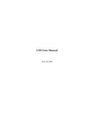
Propellants<br />
Specific impulse vacuum<br />
<strong>Thrust</strong> vacuum<br />
Propellant mass flow rate at thrust chamber inlet<br />
- LH2<br />
-LOX<br />
- Turbine exhaust gas (injected in Nozzle)<br />
<strong>Thrust</strong> chamber inlet conditions<br />
- LH2 Pressure<br />
- LH2 Temperature<br />
- LOX Pressure<br />
- LOX Temperature<br />
Mixture ratio (TC)<br />
Combustion chamber pressure<br />
Nozzle area ratio<br />
Nozzle exit diameter<br />
Overall engine length<br />
<strong>Thrust</strong> chamber mass<br />
and mixed by shear forces<br />
generated by the velocity<br />
differences between LOX and<br />
LH2. Although the injector<br />
design is complex, it does assure<br />
consistent and reliable<br />
combustion efficiencies close to<br />
99 %, which are reached during<br />
the remaining process in the<br />
combustion chamber.<br />
In the combustion chamber, the<br />
mixed propellants are burned and<br />
accelerated up to sonic<br />
conditions. The combustion<br />
temperatures in the chamber<br />
reach almost 3250 °C at<br />
pressures greater than 100 bar.<br />
Combustion temperature control<br />
is achieved by a flow of LH2 in the<br />
cooling channels within the<br />
combustion chamber wall. This<br />
thin copper alloy wall, just 1.5 mm<br />
thick separates the combustion<br />
temperatures from the - 239 to -<br />
150 °C LH2 cooling flow.<br />
The final acceleration of hot<br />
gases, up to supersonic<br />
velocities, is achieved by gas<br />
expansion in the nozzle.<br />
LOX/LH2<br />
429 s<br />
1359 kN<br />
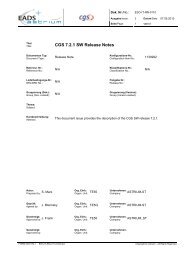
<strong>VULCAIN</strong>2:<strong>Thrust</strong> <strong>Chamber</strong><br />
40.4 kg/s<br />
272.6 kg/s<br />
10.1 kg/s<br />
182.1 bar<br />
36.0 K<br />
153.9 bar<br />
96.7 K<br />
6.74<br />
117.3 bar<br />
58.2<br />
2.09 m<br />
3.44 m<br />
909 kg<br />
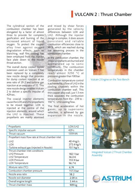
Vulcain 2 Engine on the Test-Bench<br />
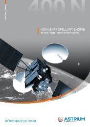
Integrated Vulcain 2 <strong>Thrust</strong> <strong>Chamber</strong><br />
Assembly