8 - LISEGA
8 - LISEGA
8 - LISEGA

You also want an ePaper? Increase the reach of your titles
YUMPU automatically turns print PDFs into web optimized ePapers that Google loves.
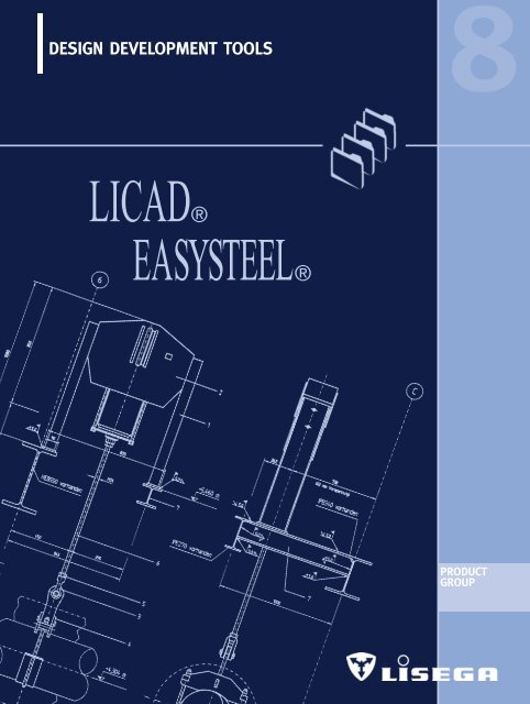
DESIGN DEVELOPMENT TOOLS<br />
LICAD®<br />
EASYSTEEL®<br />
8<br />
PRODUCT<br />
GROUP
<strong>LISEGA</strong> DESIGN DEVELOPMENT TOOLS 8<br />
CONTENTS PAGE<br />
<strong>LISEGA</strong> engineering software tools __________________________________8.1<br />
LICAD design program ____________________________________________8.2<br />
EASYSTEEL design program ________________________________________8.5<br />
Component libraries ______________________________________________8.11<br />
Interfaces to CAD programs________________________________________8.11<br />
NAVISWORKS design viewer ______________________________________8.12<br />
0<br />
1<br />
2<br />
3<br />
4<br />
5<br />
6<br />
7<br />
PRODUCT<br />
GROUP<br />
9<br />
8.0<br />
8
8.1<br />
<strong>LISEGA</strong> DESIGN DEVELOPMENT TOOLS<br />
LICAD®<br />
EASYSTEEL®<br />
Via the export function, the<br />
support designs can be integrated<br />
into complex 3D views<br />
The intelligent solution for support planning<br />
<strong>LISEGA</strong>’s unique modular system was the<br />
prerequisite for the creation of highly sophisticated<br />
user software. The solutions on hand<br />
open up new opportunities for increased<br />
engineering design efficiency, improved quality<br />
and significant savings in project manhours.<br />
The general introduction of 2D and 3D CAD<br />
modelling has already had a dramatic effect<br />
on the design process for pipework systems.<br />
However, the benefits for pipe support design<br />
have been limited because supports were not<br />
included in the 3D CAD programs.<br />
The LICAD® program has set new standards in<br />
this field. It allows the generation of pipe support<br />
drawings, bills of materials and 3-D<br />
models in minutes rather than hours. LICAD is<br />
an intelligent front-end program that provides<br />
all the required interface data for all common<br />
CAD software programs from a single source.<br />
From the point of view of quality this single<br />
source function cannot be overemphasised.<br />
To exploit further fields of application for<br />
the LICAD user, <strong>LISEGA</strong> has also developed<br />
supplementary software. The complete package<br />
includes:<br />
➜ LICAD planning and design software for<br />
pipe supports<br />
➜ EASYSTEEL design program for<br />
secondary steel<br />
➜ import and export interfaces for tables<br />
and databases<br />
➜ interfaces with 3D CAD component<br />
packages<br />
➜ 2D / 3D libraries for different CAD<br />
programs<br />
➜ interfaces to independent 3D<br />
viewer programs<br />
➜ Internet communication systems for<br />
downloading program updates and<br />
transmitting project information<br />
including drawings and orders<br />
LICAD and EASYSTEEL are trademarks of <strong>LISEGA</strong> GmbH.<br />
All other products, fonts and company names mentioned are<br />
trademarks or registered trademarks of their respective companies.
LICAD<br />
SOFTWARE WITH PROFIT EFFECT<br />
Needed first - designed last<br />
As a rule, the planning and design of complex<br />
pipe systems runs through numerous<br />
phases of optimization. Inevitably, the design<br />
of pipe supports takes place at the end of<br />
the whole process, and therefore often<br />
comes too late to ensure prompt delivery.<br />
Although the supports are needed on site<br />
beforehand in order to ensure optimum<br />
installation of the piping, they lie right at<br />
the end of the planning chain.<br />
At this point, it is even more vital to avoid<br />
unnecessary delay. The time factor is now all<br />
important.<br />
LICAD speeds up the planning process<br />
LICAD, the unique <strong>LISEGA</strong> design program<br />
for pipe supports, sets the highest standards<br />
in efficiency. With LICAD, poring over catalogs<br />
and the painstaking preparation of bills of<br />
material can be dispensed with. The design<br />
of supports and load chains no longer needs<br />
to be configured manually and then drawn<br />
up at great expense in time and money.<br />
What otherwise takes hours to produce can<br />
be done in minutes electronically - at the<br />
click of a mouse!<br />
Future orientated logistics<br />
Via LICAD, savings in time are possible in<br />
the logistics process from planning right<br />
through to delivery. For example, if required<br />
the LICAD data can be sent directly by a<br />
customer to our main<br />
computer system for order processing on the<br />
same day. This fits in well with ever tighter<br />
order schedules!<br />
The latest version is now<br />
available as Release 8 in<br />
the following languages:<br />
English, German, Spanish,<br />
Polish, French, Japanese<br />
and Chinese<br />
AutoCAD drawing based on<br />
a LICAD design<br />
8<br />
8.2
Free designation of axes<br />
Simple registration of extra data<br />
required<br />
LICAD drawing generated<br />
by a standard printer<br />
8.3<br />
LICAD is simple to use<br />
The relevant data for individual support<br />
points is entered using a menu driven program<br />
control. Only 6 parameters are required<br />
in order to find the optimum solution.<br />
➜ pipe diameter<br />
➜ temperature of the medium<br />
➜ operating load<br />
➜ travel<br />
➜ installation height<br />
➜ support configuration<br />
From this input, the appropriate load chains<br />
are created automatically and in fractions of<br />
a second. The optimum selection of variable<br />
spring and constant hangers is made by the<br />
program simultaneously. Specific customer<br />
requirements, such as travel and load reserves<br />
in accordance with ASME, B 31.3, VGB or other<br />
codes, are taken into account. This is provided<br />
for by the corresponding input in a special<br />
menu. Considering these requirements,<br />
the programmed algorithm always ensures<br />
that the most economical solution will be<br />
selected from the possible options.<br />
True to scale drawings<br />
The support chains created are automatically<br />
saved as complete assemblies and can be<br />
printed or plotted as a drawing at any time.<br />
They are true to scale and contain all<br />
relevant details, including parts lists with<br />
weights and material, and if required, pricing<br />
and location plan.<br />
<strong>LISEGA</strong> modular system forms the basis<br />
A database system forms the basis of the<br />
program which the complete <strong>LISEGA</strong> product<br />
range is incorporated into as a functional<br />
modular system. From more than 8000 standard<br />
items, compatible herein with regard to<br />
loads and connections, more than 100 standard<br />
configurations cover practically any<br />
installation situation.<br />
All essential functions at a glance<br />
Clear prompts for all significant data on the<br />
relevant support<br />
Selection of support configurations
The fully designed support with detailed bill<br />
of material<br />
Simple uniform surface for export function<br />
Auxiliary steelwork<br />
LICAD creates ready to install load chains<br />
from standard supports, from the building<br />
connection right through to the pipesurrounding<br />
attachment. In order to produce<br />
the connection to the existing structure,<br />
supplementary auxiliary structures are frequently<br />
required.<br />
Via a special interface, the appropriate LICAD<br />
designs are transferred to a separate CAD<br />
program (e.g. AutoCAD), where they can be<br />
supplemented as desired. In most cases,<br />
where designs are not to complicated,<br />
EASYSTEEL (see page 8.5) offers the ideal<br />
solution.<br />
Detailed display in 3D models<br />
Interference checks<br />
For larger plant projects, the design of the<br />
building structure, including steelwork, main<br />
components and piping, is carried out via<br />
3D CAD programs, such as PDS/Microstation<br />
(Intergraph), Plant Space (Bentley) or PDMS<br />
(CADCENTRE). Planning continuity, as well as<br />
the need to consider possible interferences,<br />
necessitate the inclusion of the pipe supports<br />
in the process. Using defined interfaces,<br />
LICAD support designs can be transferred<br />
with no additional effort three-dimensionally<br />
and true to scale into the leading CAD<br />
programs .<br />
The standard LICAD drawings are automatically<br />
transposed into 3D using special data files.<br />
LICAD saves up to 50% of planning costs<br />
LICAD runs smoothly on any modern PC with<br />
Windows and is easy to use. Due to its particular<br />
effectiveness, LICAD has already become<br />
an indispensable tool for numerous engineering<br />
departments when designing supports.<br />
Potential cost savings of up to 50% simply<br />
cannot be ignored!<br />
8<br />
Location plan with axis markings<br />
and dimensions<br />
8.4
EASYSTEEL<br />
The ideal task when designing<br />
pipe supports is to connect<br />
a pipe directly to the<br />
existing plant structure.<br />
However, due to the given<br />
support positions, in most<br />
cases the existing plant<br />
structure does not allow a<br />
suitable connenction. The<br />
support designer is then<br />
required to plan additional<br />
secondary steel, so-called<br />
auxiliary structures.<br />
Selected beam with different<br />
attachment and connecting<br />
options<br />
8.5<br />
Standard supports<br />
With LICAD, the most appropriate support<br />
configurations in each case are determined,<br />
then the corresponding standard supports in<br />
all their individual elements selected. A support<br />
drawing, parts list and 3D model can all<br />
be automatically generated using this<br />
system. If the standard supports cannot be<br />
connected directly to the existing plant structure,<br />
the next step is to use additional steel<br />
elements for the necessary adaptation.<br />
Planning secondary steel<br />
Although this steel may consist of only 1 or<br />
2 items, each design is invariably unique, its<br />
manufacture being both labour-intensive and<br />
costly using traditional techniques.<br />
Creating the design and producing a drawing<br />
and a bill of materials with the cut lengths<br />
and economic load calculations requires a<br />
significant amount of time, even for simple<br />
designs.<br />
With EASYSTEEL, <strong>LISEGA</strong> has now developed<br />
a powerful tool to reduce this time to a minimum<br />
and improve the quality of the design<br />
process. At the same time it ensures interface<br />
compatibility for electronic integration. The<br />
new <strong>LISEGA</strong> EASYSTEEL design program is a<br />
logical complement to the <strong>LISEGA</strong> modular<br />
system and the LICAD program.<br />
Concept sketch<br />
7.3 kips<br />
40<br />
790°F<br />
31 X = 0.86 inch<br />
Y = 1.45 inch<br />
Z = 1.70 inch (UP)<br />
/4<br />
20 75’ – 5 1 /2<br />
The program can be used either independently<br />
or in conjunction with data imported<br />
from a LICAD file. The user is guided menucontrolled<br />
through the design process, using<br />
easy selection screens.<br />
EASYSTEEL provides the user with the most<br />
frequently used forms of steel designs as<br />
basic elements. The most common connection<br />
types are also supplied. The user selects<br />
the appropriate design shape from the corresponding<br />
selection screens and puts in<br />
the relevant dimensions and interface data.<br />
The program then suggests beam sizes that<br />
are compatible in dimension and loading<br />
with the <strong>LISEGA</strong> attachment component. A<br />
further feature is the possibility of adaptation<br />
to the surrounding structure.<br />
After the user has decided on the preferred<br />
section size, the program generates a true<br />
to scale drawing with bill of materials and<br />
cut list.<br />
For the design elements available, EASY-<br />
STEEL contains a series of load capacity<br />
data bases. The information needed for the<br />
design-related selection of frame elements<br />
regarding weld sizes or bolt dimensions can<br />
be found here.<br />
66’
SPEZIAL FEATURES OF THE PROGRAM<br />
Connection of the pipe support to the<br />
secondary steel<br />
All <strong>LISEGA</strong> standard elements that can be<br />
attached to the secondary steel are included<br />
as an option, e. g.:<br />
➜ weld-on eye plates, weld-on clevises,<br />
types 73, 75<br />
➜ weld-on brackets, type 35<br />
➜ spherical washers, beam clamps,<br />
types 74, 78<br />
➜ clamp bases, type 49<br />
➜ constant hangers with supports,<br />
constant supports, types 11+71, type 16<br />
➜ seated spring hangers,<br />
spring supports, types 25, 26, 29<br />
➜ U-bolts, type 40<br />
➜ weld-on pipe shoes, stanchions,<br />
types 57, 58<br />
➜ roller bearings, types 51, 52, 53<br />
➜ beam adapters, type 76<br />
Selection screen for support attachment<br />
Available options among the <strong>LISEGA</strong> standard pipe support connections<br />
8<br />
8.6
American Profiles<br />
USA<br />
8.7<br />
//////<br />
//////<br />
➡<br />
C4x7.25<br />
…<br />
C12x30<br />
W4x13<br />
…<br />
W12x79<br />
W6x9<br />
…<br />
W14x38<br />
➡<br />
➡<br />
L2x2x0.25<br />
…<br />
L4x4x0.375<br />
TS3x3x0.25<br />
…<br />
TS8x8x 3 /8<br />
//////<br />
➡<br />
//////////////<br />
Standardized beam arrangements<br />
//////<br />
➡<br />
//////<br />
////////////<br />
/////////////<br />
➡<br />
➡<br />
➡<br />
➡<br />
///////////////<br />
European Profiles British Profiles<br />
D, F<br />
GB<br />
Sections (Channels)<br />
U100<br />
C102x51<br />
…<br />
…<br />
U300<br />
C305x102<br />
Wide flange sections<br />
HEB100 2*(C102x51)<br />
…<br />
…<br />
HEB300 UC305x305<br />
Small flange sections<br />
IPE140 UB127x76<br />
…<br />
…<br />
IPE360 UB356x171<br />
Angle sections<br />
L50x6 L50x50x6<br />
…<br />
…<br />
L100x10 L100x100x12<br />
Square hollow sections<br />
SHP80x6.3 TS80x80x6<br />
…<br />
…<br />
SHP200x10 TS200x200x10<br />
//////<br />
//////<br />
Height x Width<br />
approx.<br />
100 x 50<br />
…<br />
300 x 100<br />
100 x 100<br />
…<br />
300 x 300<br />
140 x 75<br />
…<br />
360 x 170<br />
50 x 50<br />
…<br />
100 x 100<br />
80 x 80<br />
…<br />
200 x 200<br />
//////////////<br />
➡<br />
➡<br />
➡<br />
//////////////<br />
➡<br />
///////////////<br />
Internal<br />
design.<br />
SC10<br />
SC30<br />
SH10<br />
SH30<br />
SI14<br />
SI36<br />
SL05<br />
SL10<br />
SQ08<br />
SQ20<br />
//////<br />
Beam systems<br />
The program allows the selection of beam<br />
arrangements most commonly used for<br />
secondary steel designs as standard:<br />
➜ beam between two<br />
existing structures<br />
➜ cantilever types<br />
➜ post types<br />
Loading of beams is possible from above<br />
or below.<br />
Section sizes<br />
The program uses virtual section sizes and<br />
covers a sufficiently wide range of commonly<br />
used beam sections for various countries.<br />
The list of programed beam sections considers<br />
American, European, Japanese and<br />
Chinese standards. After determination of a<br />
range of suitable steel sizes the designer can<br />
decide which national standards shall be<br />
used to generate the drawings.<br />
Due to the modular program, and the use of<br />
virtual section sizes, further specific national<br />
standards can be included.<br />
This system allows the flexibility to<br />
design independently of specific national<br />
standards.<br />
Ranges of selected section sizes
Attachment to existing structure<br />
The most common techniques for attachment<br />
to the existing structure are available in the<br />
program:<br />
➜ beam directly welded<br />
➜ beam with shim plates or beam with<br />
end-plate to spread the load<br />
➜ beam with bolt-on plates<br />
➜ welded clip-angle connections<br />
➜ cut-out flange connection to fit inbetween<br />
two beams (with or without end/shim plate)<br />
➜ beam end support on or under a roof<br />
girder.<br />
Weld sizes<br />
The weld sizes selected by the program are<br />
load compatible with the <strong>LISEGA</strong> modular<br />
system whether the weld is measured in<br />
throat thickness (mm) or leg length (inch,<br />
acc. to American standard).<br />
Weld sizes<br />
Throat thickness 3 56 7 9 11 13 mm<br />
Leg length 3/16 1/4 5/16 3/8 1/2 5/8 3/4 inch<br />
Connection compatibility<br />
Geometric checks are performed to avoid<br />
designs which would not fit when assembled<br />
on site. These checks include:<br />
1. for welded attachments:<br />
➜ comparison of the width of the attachment<br />
(incl. weld seam) with beam width<br />
➜ determination of the weld size suitable<br />
for the section and attachment according to<br />
prevailing rules and recommendations<br />
2. for bolted connections:<br />
➜ selection of section sizes that allow compatibility<br />
of bolt holes with each other<br />
Options of<br />
steel attachment<br />
8<br />
8.8
All relevant data can be<br />
entered in one step<br />
8.9<br />
How the program works<br />
The program is database driven, working with<br />
load capacity tables to determine the correct<br />
section, bolting and weld sizes. The concept<br />
allows the addition of other national section<br />
standards.<br />
Codes and regulations<br />
The permissible load values used to select<br />
beam and weld sizes are based on commonly<br />
recognized steelwork codes such as AISC, BS,<br />
DIN. Additionally, user specifications can be<br />
defined and considered during the selection<br />
process.<br />
USE OF THE PROGRAM<br />
User input<br />
The program requires the following inputs:<br />
➜ type designation of the attachment part<br />
➜ operating load acting on the beam<br />
➜ notation of the connection point<br />
This input can be taken directly from the<br />
LICAD file.<br />
Four continuous screens guide the user in<br />
defining:<br />
➜ positioning of the attachment<br />
➜ the beam system<br />
➜ the necessary length information<br />
➜ the type of connection to surrounding<br />
structure<br />
The scaled drawing includes all dimensions<br />
and the bill of material. The weld sizes are<br />
shown according to requirements in throat<br />
thickness (mm) or leg length (inch). The language<br />
desired can be selected from a range<br />
of the most common languages.
8<br />
A logical menu follow up<br />
guides the user through<br />
the design process<br />
8.10
COMPONENT LIBRARIES<br />
8.11<br />
Component libraries<br />
For further design in the 2D and 3D fields,<br />
<strong>LISEGA</strong> component libraries are available for<br />
the following CAD programs:<br />
➜ AutoCAD, Autodesk<br />
➜ PDS, INTERGRAPH<br />
➜ PDMS, CADCENTRE<br />
➜ SUPPORT MODELER,<br />
Pelican Forge Corp.<br />
➜ NAVISWORKS, LightWork Design<br />
The <strong>LISEGA</strong> catalog items (Standard Supports<br />
2010) are available both as text and database<br />
files.<br />
INTERFACES<br />
2D application<br />
Via a DFX export file, the support design incl.<br />
dimensions can be transferred, with bills of<br />
materials, location plans and letter heads as<br />
an option, to CAD programs, e.g. AutoCAD<br />
or MicroStation.<br />
3D application<br />
Via defined interfaces, the LICAD support<br />
designs can be transferred true to scale and<br />
without additional effort into the leading<br />
CAD programs. Using the component libraries<br />
as a basis, the standard CAD drawings can<br />
be converted to 3D in the respective CAD<br />
programs. Among others, this is possible<br />
with:<br />
➜ PDS, INTERGRAPH<br />
➜ PDMS, CADCENTRE<br />
➜ SUPPORT MODELER, Pelican Forge<br />
Corp.<br />
➜ NAVISWORKS, LightWork Design<br />
Updates<br />
LICAD, EASYSTEEL and other software packages<br />
are being constantly updated and expanded.<br />
The respective valid program versions<br />
and interfaces can be downloaded from<br />
the <strong>LISEGA</strong> homepage. The necessary license<br />
numbers are thereby issued to the user via<br />
e-mail as an automatic function. Additional<br />
numbers can also be supplied by phone.
VIEWER<br />
NAVISWORK 3D Design Viewer<br />
In partnership with LIGHTWORK DESIGN in<br />
the UK, <strong>LISEGA</strong> has created an economical<br />
and easy to utilize 3D design system for<br />
pipe supports. NAVISWORKS ROAMER is a<br />
proven 3D design review program independent<br />
of any CAD design package. It contains all the<br />
functions that a support designer requires to<br />
check a 3D plant model, the main features<br />
being:<br />
➜ navigation, communication and<br />
interaction in real-time with very<br />
large 3D models on a desktop or<br />
laptop computer.<br />
➜ interface to MicroStation<br />
(incl. PDS) and AutoCAD formats<br />
(incl. AutoPlant).<br />
➜ speed and ease in locating key<br />
components.<br />
➜ snap-on measuring tool with the<br />
ability to copy and paste dimensions<br />
into LICAD.<br />
➜ Fast Open GL graphics, enabling the<br />
quick and easy real-time navigation<br />
and viewing of very large models.<br />
➜ ease of use – non-CAD-trained staff can<br />
efficiently use the system after minimal<br />
training.<br />
➜ interference check (Clash Detector)<br />
module available.<br />
➜ export of JPEG and AVI files for<br />
transmitting design review information<br />
(pictures).<br />
➜ QA enhanced by access to a single<br />
model with up to date model description.<br />
➜ lifetime record storage of support<br />
information with reduction in lifetime<br />
maintenance costs using as-built model.<br />
Users can import 3D plant models from<br />
MicroStation and/or AutoCAD.<br />
3D pipe support models (generated in LICAD)<br />
can also be imported.<br />
<strong>LISEGA</strong> customers have the opportunity to<br />
use a full working version of the program for<br />
a 15 day trial. The program can be installed<br />
from the <strong>LISEGA</strong> Multimedia CD. Specimen<br />
models are also included on the CD.<br />
If the program is required for only one project,<br />
a program copy can be obtained through<br />
<strong>LISEGA</strong> licensed only for this project.<br />
8<br />
8.12