Powermatic Model 66 Table Saw Manual.pdf - Woodworkers Guild
Powermatic Model 66 Table Saw Manual.pdf - Woodworkers Guild
Powermatic Model 66 Table Saw Manual.pdf - Woodworkers Guild
You also want an ePaper? Increase the reach of your titles
YUMPU automatically turns print PDFs into web optimized ePapers that Google loves.
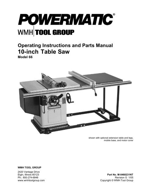
Operating Instructions and Parts <strong>Manual</strong><br />
10-inch <strong>Table</strong> <strong>Saw</strong><br />
<strong>Model</strong> <strong>66</strong><br />
WMH TOOL GROUP<br />
shown with optional extension table and legs,<br />
mobile base, and motor cover<br />
2420 Vantage Drive<br />
Elgin, Illinois 60123 Part No. M-0460231NT<br />
Ph.: 800-274-6848 Revision G 1/05<br />
www.wmhtoolgroup.com Copyright © WMH Tool Group
This manual has been prepared for the owner and operators of a <strong>Powermatic</strong> <strong>66</strong> <strong>Table</strong> <strong>Saw</strong>. Its purpose,<br />
aside from machine operation, is to promote safety using accepted operating and maintenance<br />
procedures. To obtain maximum life and efficiency from your table saw and to aid in using it safely,<br />
please read this manual thoroughly and follow the instructions carefully.<br />
Warranty and Service<br />
WMH Tool Group warrants every product it sells. If one of our tools needs service or repair, one of our<br />
Authorized Repair Stations located throughout the United States can provide quick service or information.<br />
In most cases, a WMH Tool Group Repair Station can assist in authorizing repair work, obtaining parts, or<br />
perform routine or major maintenance repair on your <strong>Powermatic</strong> product.<br />
For the name of an Authorized Repair Station in your area, please call 1-800-274-6848, or visit our web<br />
site at www.wmhtoolgroup.com<br />
More Information<br />
Remember, WMH Tool Group is consistently adding new products to the line. For complete, up-to-date<br />
product information, check with your local WMH Tool Group distributor, or visit our web site at<br />
www.wmhtoolgroup.com<br />
WMH Tool Group Warranty<br />
WMH Tool Group makes every effort to assure that its products meet high quality and durability standards<br />
and warrants to the original retail consumer/purchaser of our products that each product be free from<br />
defects in materials and workmanship as follows: 1 YEAR LIMITED WARRANTY ON ALL PRODUCTS<br />
UNLESS SPECIFIED OTHERWISE. This Warranty does not apply to defects due directly or indirectly to<br />
misuse, abuse, negligence or accidents, normal wear-and-tear, repair or alterations outside our facilities,<br />
or to a lack of maintenance.<br />
WMH TOOL GROUP LIMITS ALL IMPLIED WARRANTIES TO THE PERIOD SPECIFIED ABOVE,<br />
BEGINNING FROM THE DATE THE PRODUCT WAS PURCHASED AT RETAIL. EXCEPT AS STATED<br />
HEREIN, ANY IMPLIED WARRANTIES OR MERCHANTABILITY AND FITNESS ARE EXCLUDED.<br />
SOME STATES DO NOT ALLOW LIMITATIONS ON HOW LONG THE IMPLIED WARRANTY LASTS,<br />
SO THE ABOVE LIMITATION MAY NOT APPLY TO YOU. IN NO EVENT SHALL WMH TOOL GROUP<br />
BE LIABLE FOR DEATH, INJURIES TO PERSONS OR PROPERTY, OR FOR INCIDENTAL,<br />
CONTINGENT, SPECIAL, OR CONSEQUENTIAL DAMAGES ARISING FROM THE USE OF OUR<br />
PRODUCTS. SOME STATES DO NOT ALLOW THE EXCLUSION OR LIMITATION OF INCIDENTAL<br />
OR CONSEQUENTIAL DAMAGES, SO THE ABOVE LIMITATION OR EXCLUSION MAY NOT APPLY<br />
TO YOU.<br />
To take advantage of this warranty, the product or part must be returned for examination, postage<br />
prepaid, to an Authorized Repair Station designated by our office. Proof of purchase date and an<br />
explanation of the complaint must accompany the merchandise. If our inspection discloses a defect, we<br />
will either repair or replace the product at our discretion, or refund the purchase price if we cannot readily<br />
and quickly provide a repair or replacement. We will return the repaired product or replacement at WMH<br />
Tool Group’s expense, but if it is determined there is no defect, or that the defect resulted from causes<br />
not within the scope of WMH Tool Group’s warranty, then the user must bear the cost of storing and<br />
returning the product. This warranty gives you specific legal rights; you may also have other rights, which<br />
vary from state to state.<br />
WMH Tool Group sells through distributors only. Members of the WMH Tool Group reserve the right to<br />
effect at any time, without prior notice, alterations to parts, fittings and accessory equipment, which they<br />
may deem necessary for any reason whatsoever.<br />
2
<strong>Table</strong> of Contents<br />
Warranty and Service ..............................................................................................................................2<br />
Warning...................................................................................................................................................4<br />
Introduction..............................................................................................................................................6<br />
Specifications ..........................................................................................................................................6<br />
Unpacking ...............................................................................................................................................7<br />
Contents of the Shipping Container ......................................................................................................7<br />
Installation and Assembly ........................................................................................................................8<br />
Mounting Extension Wings ...................................................................................................................8<br />
Installing Blade.....................................................................................................................................9<br />
Mounting Rails and Accu-Fence ® .........................................................................................................9<br />
Optional Wood Extension <strong>Table</strong> ...........................................................................................................9<br />
Splitter and Guard Assembly ................................................................................................................9<br />
Motor Cover .......................................................................................................................................10<br />
Grounding Instructions...........................................................................................................................10<br />
Extension Cords.................................................................................................................................11<br />
Adjustments...........................................................................................................................................11<br />
Blade Raising and Tilting....................................................................................................................11<br />
Miter Slot Alignment ...........................................................................................................................11<br />
Tilt Stop Adjustment ...........................................................................................................................12<br />
Miter Gauge Adjustment.....................................................................................................................12<br />
Belt Tensioning ..................................................................................................................................12<br />
Splitter Alignment ...............................................................................................................................13<br />
Insert Adjustment ...............................................................................................................................13<br />
Arbor and Arbor Bearing Removal......................................................................................................13<br />
Blade Raising Mechanism Adjustment................................................................................................13<br />
Tilting Mechanism Adjustment............................................................................................................14<br />
Operating Instructions for <strong>Table</strong> <strong>Saw</strong>s....................................................................................................14<br />
Rip <strong>Saw</strong>ing.........................................................................................................................................16<br />
Resawing ...........................................................................................................................................17<br />
Crosscutting.......................................................................................................................................17<br />
Bevel and Miter Operations ................................................................................................................18<br />
Dado Cutting......................................................................................................................................19<br />
Safety Devices ...................................................................................................................................19<br />
Maintenance..........................................................................................................................................20<br />
Optional Accessories .............................................................................................................................23<br />
Replacement Parts ................................................................................................................................23<br />
Parts List: Trunnion Assembly ............................................................................................................24<br />
Trunnion Assembly.............................................................................................................................26<br />
Parts List: Miter Gauge.......................................................................................................................27<br />
Parts List: Splitter and Guard Assembly..............................................................................................28<br />
Splitter and Guard Assembly ..............................................................................................................29<br />
Parts List: Stand Assembly.................................................................................................................30<br />
Stand Assembly .................................................................................................................................31<br />
Parts List: <strong>Table</strong> Extension and Legs (Optional Accessory).................................................................32<br />
Electrical Connections ...........................................................................................................................33<br />
Maintenance Checklist...........................................................................................................................37<br />
3
Warning<br />
1. Read and understand the entire owners manual before attempting assembly or operation.<br />
2. Read and understand the warnings posted on the machine and in this manual. Failure to comply with<br />
all of these warnings may cause serious injury.<br />
3. Replace the warning labels if they become obscured or removed.<br />
4. This table saw is designed and intended for use by properly trained and experienced personnel only.<br />
If you are not familiar with the proper and safe operation of a table saw, do not use until proper<br />
training and knowledge have been obtained.<br />
5. Do not use this table saw for other than its intended use. If used for other purposes, WMH Tool Group<br />
disclaims any real or implied warranty and holds itself harmless from any injury that may result from<br />
that use.<br />
6. Always wear approved safety glasses/face shields while using this table saw. Everyday eyeglasses<br />
only have impact resistant lenses; they are not safety glasses.<br />
7. Before operating this table saw, remove tie, rings, watches and other jewelry, and roll sleeves up past<br />
the elbows. Remove all loose clothing and confine long hair. Non-slip footwear or anti-skid floor strips<br />
are recommended. Do not wear gloves.<br />
8. Wear ear protectors (plugs or muffs) during extended periods of operation.<br />
9. Some dust created by power sanding, sawing, grinding, drilling and other construction activities<br />
contain chemicals known to cause cancer, birth defects or other reproductive harm. Some examples<br />
of these chemicals are:<br />
• Lead from lead based paint.<br />
• Crystalline silica from bricks, cement and other masonry products.<br />
• Arsenic and chromium from chemically treated lumber.<br />
Your risk of exposure varies, depending on how often you do this type of work. To reduce your<br />
exposure to these chemicals, work in a well-ventilated area and work with approved safety<br />
equipment, such as face or dust masks that are specifically designed to filter out microscopic<br />
particles.<br />
10. Do not operate this machine while tired or under the influence of drugs, alcohol or any medication.<br />
11. Make certain the switch is in the OFF position before connecting the machine to the power supply.<br />
12. Make certain the machine is properly grounded.<br />
13. Make all machine adjustments or maintenance with the machine unplugged from the power source. A<br />
machine under repair should be RED TAGGED to show it must not be used until maintenance is<br />
complete.<br />
14. Remove adjusting keys and wrenches. Form a habit of checking to see that keys and adjusting<br />
wrenches are removed from the machine before turning it on.<br />
15. Keep safety guards in place at all times when the machine is in use. If removed for maintenance<br />
purposes, use extreme caution and replace the guards immediately.<br />
16. Check the alignment of the splitter, fence and miter slot to the blade. A caution decal is installed on<br />
each guard and splitter to remind the operator of the dangers of misalignment.<br />
17. Check damaged parts. Before further use of the machine, a guard or other part that is damaged<br />
should be carefully checked to determine that it will operate properly and perform its intended<br />
function. Check for alignment of moving parts, binding of moving parts, breakage of parts, mounting<br />
and any other conditions that may affect its operation. A guard or other part that is damaged should<br />
be properly repaired or replaced.<br />
18. Provide for adequate space surrounding work area and non-glare, overhead lighting.<br />
19. Keep the floor around the machine clean and free of scrap material, oil and grease.<br />
4
lahblahblah<br />
20. Keep visitors a safe distance from the work area. Keep children away.<br />
21. Make your workshop child proof with padlocks, master switches or by removing starter keys.<br />
22. Give your work undivided attention. Looking around, carrying on a conversation and “horse-play” are<br />
careless acts that can result in serious injury.<br />
23. Maintain a balanced stance at all times so that you do not fall or lean against the blade or other<br />
moving parts. Do not overreach or use excessive force to perform any machine operation.<br />
24. Use the right tool at the correct speed and feed rate. Do not force a tool or attachment to do a job for<br />
which it was not designed. The right tool will do the job better and safer.<br />
25. Use recommended accessories; improper accessories may be hazardous.<br />
26. Maintain tools with care. Keep blade sharp and clean for the best and safest performance. Follow<br />
instructions for lubricating and changing accessories.<br />
27. Check the saw blade for cracks or missing teeth. Do not use a cracked or dull blade or one with<br />
missing teeth or improper set. Make sure the blade is securely locked on the arbor.<br />
28. Keep hands clear of the blade area. Do not reach past the blade to clear parts or scrap with the saw<br />
blade running. Never saw freehand. Avoid awkward operations and hand positions where a sudden<br />
slip could cause your hand to contact the blade.<br />
29. Do not attempt to saw boards with loose knots or with nails or other foreign material, on its surface.<br />
Do not attempt to saw twisted, warped, bowed or “in wind” stock unless one edge has been jointed for<br />
guiding purposes prior to sawing.<br />
30. Do not attempt to saw long or wide boards unsupported where spring or weight could cause the<br />
board to shift position.<br />
31. Always use the splitter, blade guard, push stick and other safety devices for all operations where they<br />
can be used. On operations such as dadoing or molding where the blade guard cannot be used, use<br />
feather boards, fixtures and other safety devices and use extreme caution. Reinstall the splitter and<br />
blade guard immediately after completing the operation that required their removal.<br />
32. Be sure the saw blade rotates clockwise when viewed from the motor side (left side) of the machine.<br />
33. Turn off the machine before cleaning. Use a brush or compressed air to remove chips or debris — do<br />
not use your hands.<br />
34. Do not stand on the machine. Serious injury could occur if the machine tips over.<br />
35. Never leave the machine running unattended. Turn the power off and do not leave the machine until it<br />
comes to a complete stop.<br />
36. Remove loose items and unnecessary work pieces from the area before starting the machine.<br />
Familiarize yourself with the following safety notices used in this manual:<br />
This means that if precautions are not heeded, it may result in minor injury and/or<br />
possible machine damage.<br />
even death.<br />
This means that if precautions are not heeded, it may result in serious injury or possibly<br />
- - SAVE THESE INSTRUCTIONS - -<br />
5
Introduction<br />
This manual is provided by WMH Tool Group covering the safe operation and maintenance procedures<br />
for a <strong>Powermatic</strong> <strong>Model</strong> <strong>66</strong> <strong>Table</strong> <strong>Saw</strong>. This manual contains instructions on installation, safety<br />
precautions, general operating procedures, maintenance instructions and parts breakdown. This machine<br />
has been designed and constructed to provide years of trouble free operation if used in accordance with<br />
instructions set forth in this manual. If there are any questions or comments, please contact either your<br />
local supplier or WMH Tool Group. WMH Tool Group can also be reached at our web site:<br />
www.wmhtoolgroup.com.<br />
Specifications<br />
<strong>Model</strong> number........................................................................................................................................<strong>66</strong><br />
Maximum motor size.........................................................................................................5HP, 3600 RPM<br />
<strong>Table</strong> size with standard extensions (L x W)(in.)....................................................................... 37-1/2 x 28<br />
<strong>Table</strong> size without extension (L x W)(in.).................................................................................. 21-1/2 x 28<br />
Rip fence (L x W x H)(in.)................................................................................................41-3/4 x 4 x 2-1/2<br />
Arbor diameter (in.)...............................................................................................................................5/8<br />
<strong>Saw</strong> blade diameter (in.) ........................................................................................................................10<br />
Maximum speed of 10” saw blade (SFM) ........................................................................................ 11,000<br />
Blade tilt maximum (deg.) ......................................................................................................................45<br />
Maximum depth of cut (in.).......................................................... 3-1/8 at 90-degrees; 2-1/8 at 45-degrees<br />
Maximum cut to right of saw blade with standard extension (in.).............................................................25<br />
Maximum width of cutoff in front of saw in 1” stock (in.)..........................................................................15<br />
Maximum width of cutoff in front of saw in 3-1/8” stock (in.)..............................................................12-1/4<br />
Maximum diameter of dado (in.)...............................................................................................................8<br />
Maximum width of dado cut (in.)........................................................................................................ 13/16<br />
Drive belts ....................................................................................................................3VX (two required)<br />
<strong>Table</strong> height to floor (in.) ........................................................................................................................34<br />
Dust port diameter (in.) ............................................................................................................................4<br />
Shipping weight with motor, fence and rails (lbs.) ................................................................................. 614<br />
The above specifications were current at the time this manual was published, but because of our policy of<br />
continuous improvement, WMH Tool Group reserves the right to change specifications at any time and<br />
without prior notice, without incurring obligations.<br />
6
Unpacking<br />
Open shipping container and check for shipping<br />
damage. Report any damage immediately to<br />
your distributor and shipping agent. Do not<br />
discard any shipping material until the <strong>Table</strong><br />
<strong>Saw</strong> is assembled and running properly.<br />
Compare the contents of your container with the<br />
following parts list to make sure all parts are<br />
intact. Missing parts, if any, should be reported<br />
to your distributor. Read the instruction manual<br />
thoroughly for assembly, maintenance and<br />
safety instructions.<br />
Contents of the Shipping Container<br />
Box 1: 1 <strong>Table</strong> <strong>Saw</strong><br />
2 Extension Wings<br />
1 Miter Gauge<br />
1 Owner’s <strong>Manual</strong><br />
1 Warranty Card<br />
Box 2: 1 Splitter and Guard Assembly<br />
1 Splitter Support Shaft<br />
Contents of Hardware Bag:<br />
7<br />
2 Arbor Wrenches<br />
1 Hardware Bag*<br />
Box 3: 1 Accu-Fence ®<br />
1 Lock Handle<br />
1 Accu-Fence Owner’s <strong>Manual</strong><br />
Box 4: 1 Front Rail<br />
1 Rear Rail<br />
1 Guide Tube<br />
1 Hardware Bag<br />
Box 5: 1 Motor Cover<br />
2 Self-Tapping Screws<br />
Optional:<br />
Box 6: Formica Top Extension <strong>Table</strong><br />
Box 7: Legs for Extension <strong>Table</strong><br />
*The contents of the hardware bag are<br />
illustrated below. The contents of the Accu-<br />
Fence ® and Rail hardware can be found in the<br />
Accu-Fence ® manual.<br />
Read and understand the entire contents of this manual before attempting set-up<br />
or operation! Failure to comply may cause serious injury.
Installation and Assembly<br />
Tools required for assembly:<br />
7/16, 9/16, 3/8 and 1/2” wrenches<br />
1/8 and 3/32” hex wrenches<br />
Flat head screwdriver<br />
Hammer and wood block (or rubber hammer)<br />
1. Remove box and wood crating completely<br />
from around saw.<br />
2. Use a 9/16” wrench to remove the carriage<br />
bolt, hex nut and washer holding the<br />
extension wings together (Figure 1). Set<br />
extension wings aside for later installation.<br />
3. With a 7/16” wrench, remove the lag screws<br />
(Figure 2) holding the saw to the wood<br />
pallet. Carefully slide the saw from the pallet<br />
onto the floor.<br />
4. Tilt the saw, and pop off the metal tabs<br />
(Figure 2) that secured the saw to the pallet,<br />
by pushing down on them with your foot.<br />
The <strong>Table</strong> <strong>Saw</strong> should be placed in an area with<br />
a sturdy level floor, good ventilation and<br />
sufficient lighting. Leave enough space around<br />
the machine for mounting extension wings and<br />
rail assemblies, and loading and off-loading<br />
stock and general maintenance work.<br />
Exposed metal surfaces, such as the table top<br />
and extension wings, have been given a<br />
protective coating at the factory. This should be<br />
removed with a soft cloth moistened with<br />
kerosene. Do not use acetone, gasoline, or<br />
lacquer thinner for this purpose. Do not use<br />
solvents on plastic parts, and do not use an<br />
abrasive pad because it may scratch the<br />
surfaces.<br />
Mounting Extension Wings<br />
1. Mount the cast iron extension wings using<br />
six 3/8-16 x 1 hex head screws and six 3/8<br />
lock washers. See Figure 3. Have an<br />
assistant hold the extension wing up to the<br />
table, and insert the screws and washers.<br />
Finger tighten only.<br />
NOTE: If an assistant is not available, hold<br />
the wing in vertical position up to the saw<br />
table, insert the middle screw and lock<br />
washer finger tight, then pivot the wing to<br />
level position. Insert the other two screws<br />
and washers finger tight.<br />
2. It is important that the front edge of the wing<br />
is flush with the front edge of saw table. See<br />
Figure 4.<br />
8<br />
Figure 1<br />
Figure 2<br />
Figure 3<br />
Figure 4
3. Level the extension wing with the saw table<br />
across its entire width, using a straight edge<br />
and hammer with block of wood (or rubber<br />
hammer). See Figure 5. As each area of the<br />
wing becomes flush with the table, tighten<br />
the screw under that area. Continue until all<br />
three screws are fully tightened.<br />
4. Repeat for the other extension wing.<br />
Installing Blade<br />
NOTE: The blade must be mounted first before<br />
rails can be adjusted.<br />
To install or replace a blade, proceed as follows:<br />
Use care when working with<br />
or around sharp saw blade.<br />
1. Disconnect machine from power source.<br />
2. Remove table insert, then remove arbor nut<br />
and collar.<br />
3. Install blade, making sure the cutting teeth<br />
at the top of the blade point toward the front<br />
of the saw.<br />
4. Slide the collar on to the arbor and start the<br />
arbor nut on the threads. (NOTE: Righthand<br />
threads; turn clockwise to tighten.)<br />
Snug the arbor nut against the collar and<br />
blade with the provided arbor wrench, while<br />
holding blade with thumb and finger tips.<br />
5. Wedge a block of wood between the blade<br />
and table to prevent blade rotation, then<br />
tighten the arbor nut securely with the arbor<br />
wrench. See Figure 6.<br />
Mounting Rails and Accu-Fence ®<br />
With the extension wings properly aligned, the<br />
rail and fence assembly can now be mounted to<br />
the saw. Consult the separate Accu-Fence ®<br />
manual for instructions.<br />
Optional Wood Extension <strong>Table</strong><br />
For instructions on mounting the accessory<br />
wood extension table, or router table, consult<br />
your Accu-Fence ® manual.<br />
Splitter and Guard Assembly<br />
1. Insert the grooved end of the splitter support<br />
shaft through slot in rear of saw and into<br />
hole in trunnion. See Figure 7. Make sure<br />
the square head setscrew (A, Figure 8) is<br />
backed out enough to allow easy insertion<br />
of the splitter support shaft.<br />
9<br />
Figure 5<br />
Figure 6<br />
Figure 7<br />
Figure 8
2. With a 3/8" wrench, reach through the motor<br />
opening in the stand and tighten the square<br />
head setscrew (A, Figure 8) into the groove<br />
of the shaft. (NOTE: The groove will be in<br />
the proper position if the end of the shaft is<br />
made flush with the opposite side of the<br />
trunnion hole.) Then tighten the hex nut (B,<br />
Figure 8) up against the trunnion.<br />
3. The upright member of the rear splitter<br />
support (C, Figure 9) must be oriented<br />
toward the right of the shaft, as observed<br />
from the rear of the saw.<br />
4. Mount the splitter assembly to the two<br />
adjusting screws. See Figure 9. Place the<br />
two flanges of the splitter assembly onto the<br />
screws as shown. Snug the screws. (NOTE:<br />
Make sure the front shield (D, Figure 9)<br />
faces in toward the blade)<br />
5. The splitter and guard assembly must be<br />
aligned with the blade before operating the<br />
saw. Adjust the splitter according to the<br />
directions on page 13, "Splitter Alignment."<br />
Motor Cover<br />
1. Locate the two 1/4-20 self tapping sheet<br />
metal screws and install them in the<br />
punched holes on the saw cabinet. Do not<br />
screw down all the way, but leave the heads<br />
about 1/4" from the surface. See Figure 10.<br />
2. Lift the motor cover over these screws with<br />
the cover's bottom lip inside the saw's<br />
cabinet.<br />
3. Tighten the two screws.<br />
Grounding Instructions<br />
Electrical connections must<br />
be made by a qualified electrician in<br />
compliance with all relevant codes. This<br />
machine must be properly grounded to help<br />
prevent electrical shock and possible fatal<br />
injury.<br />
A power plug is not provided with the <strong>Model</strong> <strong>66</strong>.<br />
You may either connect the proper UL/CSA<br />
listed plug or “hardwire” the machine directly to<br />
your electrical panel provided there is a<br />
disconnect near the machine for the operator.<br />
Consult electrical drawings on pages 33-36 for<br />
further clarification of wiring setup.<br />
This machine must be grounded. Grounding<br />
provides a path of least resistance to help divert<br />
current away from the operator in case of<br />
electrical malfunction.<br />
10<br />
Figure 9<br />
Figure 10<br />
Recommended Gauges (AWG) of Extension Cords<br />
Amps<br />
25<br />
feet<br />
Extension Cord Length *<br />
50<br />
feet<br />
75<br />
feet<br />
100<br />
feet<br />
150<br />
feet<br />
200<br />
feet<br />
< 5 16 16 16 14 12 12<br />
5 to 8 16 16 14 12 10 NR<br />
8 to 12 14 14 12 10 NR NR<br />
12 to 15 12 12 10 10 NR NR<br />
15 to 20 10 10 10 NR NR NR<br />
21 to 30 10 NR NR NR NR NR<br />
*based on limiting the line voltage drop to 5V at 150% of the<br />
rated amperes.<br />
NR: Not Recommended.<br />
Figure 11
Make sure the voltage of your power supply<br />
matches the specifications on the motor plate of<br />
the machine.<br />
Extension Cords<br />
If an extension cord is necessary, make sure the<br />
cord rating is suitable for the amperage listed on<br />
the machine's motor plate. An undersize cord<br />
will cause a drop in line voltage resulting in loss<br />
of power and overheating.<br />
The chart in Figure 11 shows the correct size<br />
cord to use based on cord length and motor<br />
plate amp rating. If in doubt, use the next<br />
heavier gauge. The smaller the gauge number<br />
the heavier the cord.<br />
Adjustments<br />
Blade Raising and Tilting<br />
The front handwheel (A, Figure 12) controls the<br />
raising and lowering of the blade. The side<br />
handwheel (B, Figure 12) controls blade tilt,<br />
which is indicated by the scale (C, Figure 12).<br />
The lock knobs (D, Figure 12) are used to lock<br />
the setting of the handwheels.<br />
Miter Slot Alignment<br />
Disconnect machine from<br />
power source before making this<br />
adjustment.<br />
1. To check the alignment of the mitre slot to<br />
the blade, raise the blade to its maximum<br />
height at the 0 degree (vertical) position.<br />
2. Mark one tooth with a grease pencil and<br />
position the tooth slightly above the top<br />
edge of the table at the front.<br />
3. Raise the miter gauge slightly out of its slot<br />
to serve as a shoulder. Using a combination<br />
square against the side of the bar, slide the<br />
scale over until it touches the tip of the<br />
blade, and lock the scale in position. See<br />
Figure 13.<br />
4. Rotate the marked tooth so that it is slightly<br />
above the table top at the rear and, using<br />
the square as before, check whether the<br />
distance to the blade is the same. See<br />
Figure 14. If the distance is not the same,<br />
loosen the three mounting screws that lock<br />
the table to the cabinet (two in front, one in<br />
back) as shown in Figure 15, and nudge the<br />
table to bring the miter slot in line with the<br />
blade.<br />
11<br />
Figure 12<br />
Figure 13<br />
Figure 14<br />
Figure 15
5. The blade must be kept centered with the<br />
slot in the table insert to ensure clearance at<br />
both the 90 degree and 45 degree positions.<br />
After alignment, secure the table to the<br />
cabinet by re-tightening the three mounting<br />
screws (Figure 15).<br />
Tilt Stop Adjustment<br />
Using a combination square, check the 90<br />
degree (0) and 45 degree stops. (Figure 16<br />
shows the 90 degree stop being checked.)<br />
Adjust stop positions if required, using the stop<br />
screws as shown. Check the accuracy of the<br />
pointer at 90 degrees (0) and re-adjust if<br />
required.<br />
Miter Gauge Adjustment<br />
1. Slide the miter gauge into one of the slots<br />
on the table top.<br />
2. The miter gauge is equipped with<br />
individually adjustable index stops at 90<br />
degrees and 45 degrees right and left. The<br />
index stops can be adjusted by loosening<br />
the hex nuts and turning the three adjusting<br />
screws (A, Figure 17) as needed. After<br />
setting each stop, retighten the hex nut.<br />
3. To operate the miter gauge, loosen lock<br />
handle (B, Figure 17) and move the body of<br />
the miter gauge (C, Figure 17) to the<br />
desired angle. The miter gauge body is set<br />
to stop at 0 degrees and 45 degrees left or<br />
right. To move the miter gauge beyond<br />
these points, the stop rod (D, Figure 17),<br />
must be pulled out.<br />
4. If accurate crosscutting work is to be done<br />
using the miter gauge, check its squareness<br />
to the slot with a square as shown in Figure<br />
17. Re-adjust the stop position as required.<br />
Belt Tensioning<br />
The saw is equipped with a set of two matched<br />
belts. If they should need replacement, replace<br />
the complete set.<br />
To tension the belts:<br />
Loosen the hex screw (A, Figure 18) and nut (B,<br />
Figure 18) on the motor bracket. Pivot the motor<br />
and bracket to the right. Retighten screw (A,<br />
Figure 18) and nut (B, Figure 18).<br />
To remove and replace the belts, loosen the<br />
screw (A, Figure 18) and nut (B, Figure 18) and<br />
rotate the motor and bracket to the left as far as<br />
possible. Remove one belt at a time. After<br />
installing new belts, re-tension as indicated.<br />
12<br />
Figure 16<br />
Figure 17<br />
Figure 18
Splitter Alignment<br />
One of the most critical adjustments to help<br />
avoid kickback is the splitter adjustment. It<br />
should be checked and readjusted, if required,<br />
after each blade change.<br />
1. Lift the miter gauge bar slightly out of its<br />
slot. Place a combination square against the<br />
side of the raised up miter gauge bar and<br />
slide the scale against the top of the blade<br />
tooth and against the splitter as shown in<br />
Figure 19.<br />
2. Check the splitter for parallelism and for<br />
clearance to the miter slot. If adjustment is<br />
necessary, use the screws at the front<br />
flange and at the rear splitter support.<br />
3. Move the miter gauge to the opposite side<br />
of the blade and using the combination<br />
square, slide the scale against the top of the<br />
tooth and the splitter. Again check for<br />
parallelism and clearance. Clearance should<br />
be approximately equal on both sides of the<br />
blade.<br />
Insert Adjustment<br />
Adjust the setscrews in the insert with a 1/8 hex<br />
wrench to ensure that the insert is stable and<br />
flush with or slightly below the table top. See<br />
Figure 20.<br />
Arbor and Arbor Bearing Removal<br />
1. To remove the saw arbor, first remove the<br />
fence and rails, then remove the three<br />
mounting screws holding the table to the<br />
base (see Figure 15). Lift off the table.<br />
2. Loosen the two set screws in the arbor<br />
sheave (A, Figure 21) and remove the<br />
sheave and key.<br />
3. Loosen the set screw (B, Figure 21) on the<br />
saw raising arm. The arbor assembly and<br />
bearings will slide out of the arm housing.<br />
Blade Raising Mechanism<br />
Adjustment<br />
If binding occurs, clean off all sawdust and pitch<br />
buildup and re-lubricate with a good nonhardening<br />
grease. If binding continues, check<br />
the fit-up of the worm and worm gear segment.<br />
The worm must be centered with the worm gear<br />
segment. If it is not centered, loosen the saw<br />
raising arm set screws, move the arm as<br />
required, and re-lock the set screws. See Figure<br />
22.<br />
13<br />
Figure 19<br />
Figure 20<br />
Figure 21<br />
Figure 22
If the saw raising arm has been re-located, the<br />
table may have to be realigned so as to provide<br />
clearance between the saw blade and table<br />
insert slot. The splitter will also have to be<br />
realigned.<br />
NOTE: The saw arm setscrew must be tight to<br />
avoid the possibility of movement which could<br />
cause the blade to hit the insert.<br />
Tilting Mechanism Adjustment<br />
If binding occurs in the tilting mechanism, clean<br />
off the saw dust and pitch accumulation and regrease.<br />
If binding continues, check the<br />
alignment and readjust as required to center<br />
worm with the worm gear segment on the<br />
trunnion.<br />
If there is excessive play, loosen bracket<br />
mounting screws (A, Figure 23) and turn<br />
adjustment screw (B, Figure 23) clockwise to<br />
raise pinion. A tight mesh without binding is<br />
ideal. Re-tighten mounting screws and check<br />
over the 90 degree to 45 degree range of tilt for<br />
excessive play or binding. Re-adjust if required.<br />
Operating Instructions for<br />
<strong>Table</strong> <strong>Saw</strong>s<br />
1. Familiarize yourself with the location and<br />
operation of all controls and adjustments<br />
and the use of accessories such as the<br />
miter gauge and rip fence.<br />
2. Serious injury can result from kickbacks<br />
which occur when a work piece binds on the<br />
saw blade or binds between the saw blade<br />
and rip fence or other fixed object. This<br />
binding can cause the work piece to lift up<br />
and be thrown toward the operator. Listed<br />
below are the conditions which can cause<br />
kickbacks:<br />
• Confining the cutoff piece when<br />
crosscutting or ripping.<br />
• Releasing the work piece before<br />
•<br />
completing the operation or not pushing<br />
the work piece all the way past the saw<br />
blade.<br />
Not using the splitter when ripping or not<br />
maintaining alignment of the splitter with<br />
the saw blade.<br />
• Using a dull saw blade.<br />
• Not maintaining alignment of the rip<br />
fence so that it tends to angle toward<br />
instead of away from the saw blade<br />
front to back.<br />
14<br />
Figure 23
• Applying feed force when ripping to the<br />
cutoff (free) section of the work piece<br />
instead of the section between the saw<br />
blade and fence.<br />
• Ripping wood that is twisted (not flat), or<br />
does not have a straight edge, or has a<br />
twisted grain.<br />
3. To minimize or prevent injury from<br />
kickbacks:<br />
Avoid conditions listed above.<br />
<br />
Wear a safety face shield, goggles, or<br />
<br />
glasses.<br />
Do not use the miter gauge and rip<br />
<br />
fence in the same operation unless<br />
provision is made by use of a facing<br />
board on the fence so as to allow the<br />
cutoff section of the workpiece to come<br />
free before the next cut is started (See<br />
Figure 32).<br />
As the machine receives use, the<br />
<br />
operation of the anti-kickback pawls<br />
should be checked periodically. See<br />
Figure 24. If the pawls do not stop the<br />
reverse motion of a workpiece, resharpen<br />
all the points.<br />
Where possible, keep your face and<br />
<br />
body out of line with potential kickbacks<br />
including when starting or stopping the<br />
machine.<br />
4. Dull, badly set, improper, or improperly filed<br />
cutting tools and cutting tools with gum or<br />
resin adhering to them can cause accidents.<br />
Never use a cracked saw blade. The use of<br />
a sharp, well maintained, and correct cutting<br />
tool for the operation will help to avoid<br />
injuries.<br />
5. Support the workpiece properly and hold it<br />
firmly against the gauge or fence. Use a<br />
push stick or push block when ripping short,<br />
narrow (6" width or less), or thin workpieces.<br />
Use a push block or miter gauge hold-down<br />
when dadoing or molding.<br />
6. For increased safety in crosscutting, use an<br />
auxiliary wood facing attached to the miter<br />
gauge using the holes provided in the<br />
gauge, Figure 25.<br />
7. Never use the fence as a length stop when<br />
crosscutting. Do not hold or touch the free<br />
end or cutoff section of a workpiece. On<br />
through-sawing operations, the cutoff<br />
section must NOT be confined.<br />
8. Always keep your hands out of the line of<br />
the saw blade and never reach back of the<br />
cutting blade with either hand to hold the<br />
workpiece.<br />
15<br />
Figure 24<br />
Figure 25
9. Bevel ripping cuts should always be made<br />
with the fence on the right side of the saw<br />
blade so that the blade tilts away from the<br />
fence and minimizes the possibility of the<br />
work binding and the resulting kickback.<br />
Rip <strong>Saw</strong>ing<br />
1. Ripping is where the work piece is fed with<br />
the grain into the saw blade using the fence<br />
as a guide and a positioning device to<br />
ensure the desired width of cut. See Figure<br />
26.<br />
Before starting a rip cut, be<br />
sure the fence is clamped securely and<br />
aligned properly.<br />
Never rip freehand or use the miter gauge in<br />
combination with the fence.<br />
Never rip workpieces shorter than the saw<br />
blade diameter.<br />
Never reach behind the blade with either<br />
hand to hold down or remove the cutoff<br />
piece with the saw blade rotating.<br />
2. Always use the saw guard, splitter and antikickback<br />
pawls. Make sure the splitter is<br />
properly aligned. When wood is cut along<br />
the grain, the kerf tends to close and bind<br />
on the blade and kickbacks can occur.<br />
NOTE: A caution decal is installed on the<br />
guard and splitter assembly, warning of the<br />
hazard of misalignment.<br />
3. The rip fence should be set for the width of<br />
the cut by using the scale on the front rail, or<br />
by measuring the distance between the<br />
blade and fence. See Figure 27. Stand out<br />
of line with the saw blade and workpiece to<br />
avoid sawdust and splinters coming off the<br />
blade or a kickback, if one should occur.<br />
4. If the workpiece does not have a straight<br />
edge, provide one by nailing an auxiliary<br />
straight edged board on it to slide along the<br />
fence. To cut properly, the board must make<br />
good contact with the table. If it is warped,<br />
turn the hollow side down.<br />
5. In ripping, use one hand to hold the board<br />
down against the fence or fixture, and the<br />
other to push it into the blade between the<br />
blade and the fence. If the workpiece is<br />
narrower than 6" or shorter than 12", use a<br />
push stick or push block to push it through<br />
between the fence and saw blade. See<br />
Figure 28.<br />
16<br />
Figure 26<br />
Figure 27<br />
Figure 28
6. Never push in a location such that the<br />
pushing hand is in line with the blade. Move<br />
the hand serving as a hold-down a safe<br />
distance from the blade as the cut nears<br />
completion.<br />
7. For very narrow ripping where a push stick<br />
cannot be used, use a push block or<br />
auxiliary fence. Always push the workpiece<br />
completely past the blade at the end of a cut<br />
to minimize the possibility of a kickback.<br />
8. When ripping long boards, use a support at<br />
the front of the table, such as a roller stand,<br />
and a support or "tailman" at the rear as<br />
shown in Figure 29.<br />
9. Never use the rip fence beyond the point<br />
where the carriage is flush with the end of<br />
the rails.<br />
10. Have the blade extend about 1/8" above the<br />
top of the workpiece. Exposing the blade<br />
above this point can be hazardous.<br />
Resawing<br />
1. Resawing is a ripping operation in which<br />
thick boards are cut into thinner ones.<br />
Narrow boards up to 3" can be resawn in<br />
one pass. Wider boards up to 6" must be<br />
resawn in two passes.<br />
2. In resawing wider boards, adjust the blade<br />
height so as to overlap the two cuts by 1/2"<br />
as shown in Figure 30. Too deep a first cut<br />
can result in binding and possible kickbacks<br />
on the second cut. Always use the same<br />
side of the board against the fence for both<br />
cuts.<br />
Crosscutting<br />
1. Crosscutting is where the workpiece is fed<br />
cross grain into the saw blade using the<br />
miter gauge to support and position the<br />
workpiece. See Figure 31. Crosscutting<br />
should never be done freehand nor should<br />
the fence be used as an end stop unless an<br />
auxiliary block is clamped in front of the<br />
blade area such that the cutoff piece comes<br />
free of the block before cutting starts. See<br />
Figure 32. Length stops should not be used<br />
on the free end of the workpiece in the<br />
cutoff area.<br />
2. Do not crosscut workpieces shorter than 6".<br />
Before starting a cut, be sure the miter<br />
gauge is securely clamped at the desired<br />
angle. Hold the workpiece firmly against the<br />
table and back against the miter gauge.<br />
Always use the saw guard and splitter and<br />
make sure the splitter is properly aligned.<br />
17<br />
Figure 29<br />
Figure 30<br />
Figure 31<br />
Figure 32
3. For 90 degree crosscutting, most operators<br />
prefer to use the left-hand miter gauge slot.<br />
When using it in this position, hold the<br />
workpiece against the miter gauge with the<br />
left hand and use the right hand to advance<br />
the workpiece, as shown in Figure 32. When<br />
using the right hand slot for miter and<br />
compound crosscutting so that the blade<br />
tilts away from the miter gauge, the hand<br />
positions are reversed.<br />
4. When using the miter gauge, the workpiece<br />
must be held firmly and advanced smoothly<br />
at a slow rate. If the workpiece is not held<br />
firmly, it can vibrate causing it to bind on the<br />
blade and dull the saw teeth.<br />
5. To improve the effectiveness of the miter<br />
gauge in crosscutting, some users mount an<br />
auxiliary wooden extension face (with a<br />
glued-on strip of sandpaper) to the miter<br />
gauge as shown in Figure 33.<br />
6. Provide auxiliary support for any workpiece<br />
extending beyond the table top with a<br />
tendency to sag and lift up off the table.<br />
7. Stop rods can be used in the holes provided<br />
in the miter gauge for repetitive work of<br />
equal length. Do not use a stop rod on the<br />
free end of a workpiece. It should be used<br />
on the side of the miter gauge opposite the<br />
saw blade.<br />
8. Have the blade extend about 1/8" above the<br />
top of the workpiece. Exposing the blade<br />
above this point can be hazardous.<br />
Bevel and Miter Operations<br />
1. A bevel cut is a special type of operation<br />
where the saw blade is tilted at an angle<br />
less than 90 degrees to the table top. See<br />
Figure 34. Operations are performed in the<br />
same manner as ripping or crosscutting<br />
except the fence or miter gauge should be<br />
used on the right-hand side of the saw blade<br />
to provide added safety in avoiding a<br />
binding action between the saw blade and<br />
the table top. When beveling with the miter<br />
gauge, the workpiece must be held firmly to<br />
prevent creeping.<br />
2. Crosscuts made at an angle to the edge of<br />
the workpiece are called miters. See Figure<br />
35. Set and secure the miter gauge at the<br />
required angle, and make the cut the same<br />
as a normal crosscut except the workpiece<br />
must be held extra firmly to prevent<br />
creeping.<br />
18<br />
Figure 33<br />
Figure 34<br />
Figure 35
NOTE: When making compound miters<br />
(with blade tilted) use the miter gauge in the<br />
right hand slot to provide more hand<br />
clearance and safety.<br />
3. Have the blade extend only 1/8" above the<br />
top of the workpiece. Exposing the blade<br />
above this point can be hazardous.<br />
Dado Cutting<br />
Dadoing is cutting a wide groove into a<br />
workpiece or cutting a rabbet along the edge of<br />
a workpiece. A dado insert, shown in Figure 36,<br />
is necessary for this type of operation.<br />
Do not use the standard<br />
table insert for dadoing operations.<br />
The process of cutting 1/8" to 13/16" grooves in<br />
workpieces is accomplished by the use of a<br />
stacked dado blade set or an adjustable blade<br />
mounted on the saw arbor.<br />
By using various combinations of the stacked<br />
dado blades, or properly setting the dial on an<br />
adjustable blade, an accurate width dado can be<br />
made. This is very useful for shelving, making<br />
joints, tenoning, etc.<br />
The guard, splitter, and anti-kickback pawls<br />
supplied with the saw should be used for all<br />
cutting operations where they can be used.<br />
When performing operations where the guard<br />
can not be used, as in some dadoing<br />
operations, alternative safety precautions should<br />
be taken. These include push sticks, feather<br />
boards, filler pieces, fixtures, jigs and any other<br />
appropriate device that can be utilized to keep<br />
operator's hands away from the blade.<br />
Upon completion of the operation requiring<br />
removal of the guard, the entire guard assembly<br />
must be placed back on the machine in its<br />
proper working order.<br />
Never use a dado head in a<br />
tilted position. Never operate the saw<br />
without the guard, splitter and anti-kickback<br />
pawls for operations where they can be<br />
used.<br />
Safety Devices<br />
Feather Board (Figure 37).<br />
The feather board should be made of straight<br />
grain hardwood approximately 1" thick and 4" to<br />
8" wide depending on the size of the machine.<br />
The length is developed in accordance with<br />
intended use.<br />
Feather boards can be fastened to the table or<br />
rip fence by use of C-clamps.<br />
19<br />
Figure 36<br />
Figure 37
Alternatively, drilled and tapped holes in the<br />
table top allow the use of wing nuts and washers<br />
as a method of clamping. If this method of<br />
fastening is used, provide slots in the feather<br />
board for adjustment.<br />
Figure 37 shows a method of attaching and use<br />
of the feather board as a vertical comb. The<br />
horizontal application is essentially the same<br />
except that the attachment is to the table top.<br />
Filler Piece (Figure 38).<br />
A filler piece is necessary for narrow ripping and<br />
permits the guard to remain on the machine. It<br />
also provides space for the safe use of a push<br />
stick.<br />
Push Block & Push Stick (Figures 39 & 40).<br />
These items help feed the workpiece along<br />
fence and blade while keeping the operator's<br />
hands at a safe distance from the blade.<br />
Maintenance<br />
Good saw operation requires periodic preventive<br />
maintenance.<br />
Keep the inside of the cabinet and trunnion area<br />
clean. A stiff brush will remove sawdust before<br />
it cakes and pitch or gum is easily removed with<br />
a commercial solvent or with a good oven<br />
cleaner. To accomplish this, remove the table<br />
by removing the three mounting screws (see<br />
Figure 15) and exposing the working<br />
mechanisms of the saw. After cleaning the tilting<br />
and raising worm and worm gear segments and<br />
the trunnions, grease these three areas with a<br />
good grade non-hardening grease.<br />
Check periodically for excessive play in the<br />
tilting and raising mechanism and in the saw<br />
arbor and re-adjust as required.<br />
Check periodically for belt tension and wear.<br />
Readjust or replace belts as required.<br />
The table surface must be kept clean and free of<br />
rust for best results. Apply a coat of paste wax<br />
to the surface to facilitate this. An alternative is<br />
to apply white talcum powder, rubbed in<br />
vigorously once a week with a blackboard<br />
eraser; this will fill casting pores and form a<br />
moisture barrier. This method provides a table<br />
top that is slick and allows rust rings to be easily<br />
wiped from the surface. Important also is the<br />
fact that talcum powder will not stain wood or<br />
mar finishes as wax pickup does.<br />
20<br />
Figure 38<br />
Figure 39
Figure 40<br />
21
Troubleshooting<br />
Trouble Probable Cause Remedy<br />
Excessive vibration.<br />
Cuts out-of-square<br />
when crosscutting.<br />
Motor stalls or<br />
workpiece binds or<br />
burns.<br />
Cuts not true at 90 or<br />
45 degrees.<br />
Tilt or saw raising<br />
handwheels difficult<br />
to turn.<br />
Motor overheats.<br />
Motor starts slowly or<br />
fails to come up to<br />
speed.<br />
Motor fails to develop<br />
full power.<br />
Tilt or raising clamp knobs not<br />
tightened.<br />
22<br />
Tighten knobs.<br />
Blade out of balance. Change blade. [page 9]<br />
Bad motor. Replace motor.<br />
Loose arbor or motor sheave. Tighten set screws. [page 13]<br />
Miter gauge out of adjustment. Reset stops and pointer. [page 12]<br />
Miter slot misaligned. Realign table. [page 11]<br />
Excessive feed. Reduce feed.<br />
Bad motor. Replace motor.<br />
Dull or incorrect blade. Replace blade. [page 9]<br />
Miter slot misaligned. Realign miter slot. [page 11]<br />
Fence misalignment. Realign fence. [see Fence manual]<br />
Stop screws not set properly. Readust stop screws. [page 12]<br />
Lock knob not released. Loosen lock knob.<br />
Worm and worm gear segment caked<br />
with sawdust and pitch.<br />
Worm and worm gear segment out of<br />
alignment.<br />
Motor overloaded.<br />
Improper cooling of motor.<br />
Low voltage.<br />
Clean and re-grease.<br />
Realign worm and worm gear<br />
segment. [page 13]<br />
Centrifugal switch not operating. Replace switch.<br />
Bad motor. Replace motor.<br />
Correct overload condition such as<br />
reducing the feed rate.<br />
Clean sawdust from fan and duct<br />
areas of motor.<br />
Request voltage check from power<br />
company and correct low voltage<br />
condition.<br />
Power line overloaded. Correct overload condition.<br />
Undersize wires in supply system. Increase supply wire size.<br />
Low voltage.<br />
Bad motor. Replace motor.<br />
Request voltage check from power<br />
company and correct condition.
Optional Accessories<br />
709689 Scoring <strong>Saw</strong> attachment retrofit kit.<br />
2042335 Mobile base extended for <strong>Model</strong> <strong>66</strong> <strong>Saw</strong> (closed stand).<br />
2042336 Mobile base standard (fits saw stand only).<br />
2042342 Mobile base open bottom for <strong>Model</strong> <strong>66</strong> <strong>Saw</strong> (open stand).<br />
2042372 Mobile base with 30" fence with Rout-R-Lift.<br />
2195042K Accu-Fence ® and rail system for ripping 50" to right and 12" to left of saw blade.<br />
2195079 Accu-Fence ® - fence assembly only, no rails - for <strong>Model</strong> <strong>66</strong>.<br />
2195049K Accu-Fence ® and rail system for <strong>Model</strong> <strong>66</strong> w/sliding table.<br />
2195063K Accu-Fence ® and rail system for ripping 30" to right and 12" to left of saw blade.<br />
2250116 Blade guard and Splitter Assembly. Wt. 10 lbs. (4.5 kg).<br />
2328001 <strong>Table</strong> Insert.<br />
2328002 Dado Insert Plate for 8" dado head. Wt. 1 lb. (.45 kg).<br />
2726008 Replacement side panel kit for <strong>Model</strong> <strong>66</strong> Accu-Fence ® .<br />
2440020 Rear Lock Assembly for Accu-Fence ® .<br />
2471015 Miter Gauge. Wt. 4 lbs. (1.8kg).<br />
3104<strong>66</strong>3 Motor cover (old style).<br />
3104<strong>66</strong>7 Motor cover for serial # 95<strong>66</strong>2522 and up<br />
3186008 8" (203.2 mm) Cast Iron Extension Wing.<br />
6080143 Blade 35 tooth carbide tip.<br />
6080144 Blade 50 tooth carbide tip.<br />
6253118K Sliding <strong>Table</strong> Retrofit Kit, 50" crosscut capacity.<br />
6284600 Tenoning Jig.<br />
2328003 Zero Clearance Insert.<br />
6441000 Set of 2 legs for 6827028 table.<br />
<strong>66</strong>82004 Rout-R-Lift with deluxe fence.<br />
6827028 Formica topped table for 50" capacity T-square system.<br />
6827031 <strong>Table</strong> 28" x 35-3/8" with Rout-R-Lift hole for model <strong>66</strong> saw.<br />
6827032 <strong>Table</strong> 28" x 24" with Rout-R-Lift hole for model <strong>66</strong> saw.<br />
Replacement Parts<br />
Replacement parts are listed on the following pages. To order parts or reach our service department, call<br />
1-800-274-6848 between 7:00 a.m. and 6:00 p.m. (CST), Monday through Friday. Having the <strong>Model</strong><br />
Number and Serial Number of your machine available when you call will allow us to serve you quickly and<br />
accurately.<br />
23
Parts List: Trunnion Assembly<br />
Index No. Part No. Description Size Qty<br />
.................2810012.................. Trunnion Assembly (Items 1 thru 65)............ .........................................1<br />
.................2271035.................. Handwheel Assembly (Items 2 thru 7).......... .........................................2<br />
2...............2271036.................. Handle Assembly (Items 4, 6, 7) .................. .........................................2<br />
3...............3271084.................. Handwheel .................................................. 8” diameter .......................2<br />
4...............3271085.................. Handle......................................................... .........................................2<br />
5...............TS-1524031 ............ Socket Set Screw* ....................................... M8 x 12.............................2<br />
6...............6716221.................. Slotted Fillister Head Cap Screw* ................ M10 x 95.25......................2<br />
7...............6516029.................. Hex Jam Nut* .............................................. M10 ..................................2<br />
8...............2810013.................. Center Trunnion Sub-Assembly .................. .........................................1<br />
(Items 9, 25, 29, 30, 35, 40 thru 43, and 46)<br />
9...............3810041.................. Center Trunnion with Fasteners (Items 29, 30, 59, 60) ...........................1<br />
.................2701010.................. Tilting Bracket Assembly (Items 11 thru 18, 64)......................................1<br />
.................2865001.................. Tilting Shaft Assembly (Items 13, 15, 16) ..... .........................................1<br />
11.............3065006.................. Tilting Bracket.............................................. .........................................1<br />
13.............3701031.................. Tilting Shaft ................................................. .........................................1<br />
14.............6861901.................. Nylon Washer*............................................. E12, 3/4 I.D.......................4<br />
15.............<strong>66</strong>26080.................. Spring Pin* .................................................. 5mm dia. x 28 ...................2<br />
16.............3865001.................. Worm........................................................... .........................................2<br />
17.............3096247.................. Shaft Collar with Fasteners .......................... .........................................2<br />
18.............TS-1520411 ............ Socket Set Screw* ....................................... M8 x 8...............................4<br />
19.............3582222.................. Shaft Locking Pin......................................... .........................................2<br />
20.............3237360.................. Gear Segment with Fasteners (Items 21 thru 24) ...................................1<br />
21.............TS-1491061 ............ Hex Head Cap Screw* ................................. M10 x 40...........................1<br />
22.............TS-2210451 ............ Hex Head Cap Screw* ................................. M10 x 45...........................1<br />
23.............TS-1550071 ............ Flat Washer*................................................ M10 ..................................2<br />
24.............TS-2361101 ............ Lock Washer* .............................................. M10 ..................................2<br />
25.............2025039.................. Bearing Arm Assembly (Items 26 thru 34) .... .........................................1<br />
26.............3025265.................. Bearing Arm ................................................ .........................................1<br />
27.............6714273.................. Stud* ........................................................... M12 x 67...........................1<br />
28.............6714274.................. Square Head Set Screw* ............................. M10 x 25...........................1<br />
29.............TS-149105 .............. Hex Head Cap Screw* ................................. M10 x 35...........................1<br />
30.............6516029.................. Hex Jam Nut................................................ M10 ..................................1<br />
31.............2087001.................. Dust Chute .................................................. .........................................1<br />
32.............TS-1490011 ............ Hex Cap Screw* .......................................... M8 x 12.............................1<br />
33.............TS-1551051 ............ Lock Washer* .............................................. M8 ....................................1<br />
34.............TS-1525021 ............ Socket Set Screw* ....................................... M10 x 12...........................1<br />
35.............2690067.................. Screw Assembly Splitter* (Items 36 thru 39). .........................................1<br />
36.............3691046.................. Adjusting Screw........................................... .........................................1<br />
37.............6572007.................. Spanner Nut ................................................ M20 x 1.5..........................1<br />
38.............TS-1491021 ............ Hex Head Cap Screw .................................. M10 x 20...........................1<br />
39.............TS-2361101 ............ Lock Washer................................................ M10 ..................................1<br />
40.............3711005.................. Pivot Shaft................................................... .........................................1<br />
41.............6811327.................. Spacer......................................................... .........................................2<br />
42.............6578006.................. Hex Nut*...................................................... 1 1 /8 -12..............................1<br />
43.............<strong>66</strong>70092.................. Retainer Ring* ............................................. .........................................1<br />
44.............3480015.................. Motor Mount ................................................ .........................................1<br />
45.............3810023.................. Front Trunnion............................................. .........................................1<br />
46.............2865002.................. Raising Shaft Assembly (Items 15, 16, 47)... .........................................1<br />
47.............3701032.................. Raising Shaft ............................................... .........................................1<br />
48.............3735075.................. Spacer......................................................... .........................................1<br />
.................2024018.................. Arbor Assembly (Items 52 thru 58)............... .........................................1<br />
52.............3700123.................. Arbor Shaft .................................................. .........................................1<br />
53.............<strong>66</strong>70015.................. Retainer Ring............................................... #5100-78 ..........................2<br />
54.............3737214.................. Spacer......................................................... .........................................1<br />
55.............6060009.................. Bearing NSK................................................ 6204 .................................2<br />
56.............6863004.................. Wavy Washer .............................................. W1819-020 .......................1<br />
57.............3838006.................. Collar........................................................... .........................................1<br />
24
Index No. Part No. Description Size Qty<br />
58.............3530006.................. Nut .............................................................. 5/8-12 ACME ....................1<br />
59.............3604036.................. Pointer......................................................... .........................................1<br />
60.............6780015.................. Button Head Socket Cap Screw*.................. M4 x 10.............................1<br />
61.............6780016.................. Square Head Set Screw* ............................. M10 x 65...........................1<br />
63.............3810040.................. Rear Trunnion.............................................. .........................................1<br />
64.............6420002.................. Woodruff Key............................................... #608 .................................3<br />
65.............3868032.................. Arbor Wrench .............................................. .........................................2<br />
<strong>66</strong>.............3700090.................. Splitter Support Shaft................................... .........................................1<br />
67.............6716035.................. Hex Head Screw.......................................... 3/8-16 x 1-3/4....................4<br />
68.............6861300.................. Lock Washer................................................ 3/8 ..................................10<br />
69.............6516001.................. Hex Nut ....................................................... 3/8-16 ...............................6<br />
70.............6714159.................. Socket Set Screw ........................................ 1/4-20 x 3/8.......................1<br />
71.............6807132.................. Arbor Sheave............................................... 2-Groove...........................1<br />
72.............6716031.................. Hex Head Screw.......................................... 3/8-16 x 1..........................1<br />
73.............6861501.................. Flat Washer ................................................. 1/2 ....................................2<br />
74.............6518001.................. Hex Nut ....................................................... 1/2-13 ...............................2<br />
75.............6472028.................. Electric Motor, 3HP, 1Ph, 3600 RPM, 230V, 145 TC Frame ...................1<br />
.................6472033.................. Electric Motor, 3HP, 1Ph, 3600 RPM, 230V, 145 TC Frame (50Hz)<br />
.................6471720.................. Electric Motor, 2HP, 3Ph, 3600 RPM, 230/460V, 145 TC Frame<br />
.................6471723.................. Electric Motor, 2HP, 1Ph, 3600 RPM, 115/230V, 145 TC Frame<br />
.................6472024.................. Electric Motor, 3HP, 3Ph, 3600 RPM, 200V, 147 TC Frame<br />
.................6472025.................. Electric Motor, 3HP, 3Ph, 3600 RPM, 230/460V, 145 TC Frame<br />
.................6472307.................. Electric Motor, 5HP, 3Ph, 3600 RPM, 230/460V, 184 C Frame<br />
.................6472335.................. Electric Motor, 5HP, 1Ph, 3600 RPM, 230V, 184 C Frame<br />
76.............6718017.................. Hex Head Cap Screw .................................. 1/2-13 x 1-3/4....................1<br />
77.............6807133.................. Motor Sheave .............................................. 2-Groove...........................1<br />
78.............6715013.................. Socket Set Screw ........................................ 5/16-18 x 3/8.....................1<br />
79.............6077225.................. Belt (2 required)........................................... .........................................2<br />
80.............6516009.................. Hex Jam Nut................................................ 3/8-16 ...............................1<br />
81.............6716079.................. Square Head Screw..................................... 3/8-16 x 1..........................1<br />
82.............6716082.................. Square Head Screw..................................... 3/8-16 x 2-1/2....................1<br />
.................2380019.................. Hardware Kit* (not shown) .......................... ...........................................<br />
* Items included with hardware kit.<br />
25
Trunnion Assembly<br />
26
Parts List: Miter Gauge<br />
Index No. Part No. Description Size Qty<br />
.................2471015.................. Mitre Gauge Assembly (Items 1 Thru 14) ........... ...................................1<br />
1...............3044053.................. Mitre Gauge Bar ................................................ ...................................1<br />
2...............3230038.................. Mitre Gauge....................................................... ...................................1<br />
3...............3604035.................. Mitre Gauge Pointer........................................... ...................................1<br />
4...............3585221.................. Stop Pin............................................................. ...................................1<br />
5...............3841202.................. Mitre Gauge Bar Washer ................................... ...................................1<br />
6...............6506001.................. Hex Nut ............................................................. # 6-32.........................3<br />
7...............<strong>66</strong>23012.................. Dowel Pin .......................................................... 1/4 x 1 ........................1<br />
9...............6706015.................. Fillister Head Machine Screw............................. 6-32 x 5/8 ...................3<br />
11.............6714053.................. Flat Head Cap Screw......................................... 1/4-20 x 3/8 ................1<br />
12.............6861101.................. Plain Flat Washer .............................................. 1/4..............................1<br />
13.............3695221.................. Locking Screw ................................................... 1/4 x 3-3/8 ..................1<br />
14.............3268050.................. Mitre Gauge Handle Knob.................................. ...................................1<br />
15.............3055435.................. Pointer Block ..................................................... ...................................1<br />
27
Parts List: Splitter and Guard Assembly<br />
Index No. Part No. Description Size Qty<br />
.................2787008.................. Splitter Rear Support Assembly (Items 1 thru 7) ...................................1<br />
1...............6715034.................. Hex Head Cap Screw ........................................ 5/16-18 x 1-1/4 ...........1<br />
2...............6861200.................. Lock Washer...................................................... 5/16 ............................1<br />
3...............3776050.................. Splitter Rear Support ........................................ ...................................1<br />
4...............6572007.................. Spanner Lock Nut .............................................. 3/4-16 ........................1<br />
5...............3690232.................. Adjustment Screw.............................................. 3/4-16 x 1-1/2 ............1<br />
6...............2406001.................. Knob Assembly.................................................. ...................................1<br />
7...............3700090.................. Splitter Support Shaft ........................................ ...................................1<br />
.................2250116.................. Guard and Splitter Assembly (Items 8 thru 28) ... ...................................1<br />
8...............6851101.................. Flat Washer ....................................................... 1/4..............................2<br />
9...............6714158.................. Hex Head Cap Screw ........................................ 1/4-20 x 5/8 ...............1<br />
10.............6714192.................. Flat Head Socket Screw..................................... 1/4 x 20 x 7/8..............8<br />
11.............3250112.................. Blade Guard ..................................................... ...................................2<br />
12.............3838015.................. Pivot Washer ..................................................... ...................................4<br />
13.............6514012.................. Lock Nut ............................................................ 1/4-20.........................4<br />
14.............<strong>66</strong>26029.................. Spring Pin.......................................................... 3/16 x 1 ......................1<br />
15.............<strong>66</strong>26050.................. Spring Pin.......................................................... 3/8 x 1-3/4 ..................1<br />
16.............3720018.................. Guard Shield...................................................... ...................................1<br />
17.............6710032.................. Round Head Machine Screw.............................. No. 10-24 x 1/4...........2<br />
18.............3720017.................. Front Shield ....................................................... ...................................1<br />
19.............6714053.................. Flat Head Machine Screw.................................. No. 10-24 x 3/8...........2<br />
20.............3055095.................. Pivot Block......................................................... ...................................1<br />
21.............3025074.................. Pivot Arm........................................................... ...................................4<br />
22.............3070108.................. Pivot Bushing..................................................... ...................................8<br />
23.............6514001.................. Hex Nut ............................................................. 1/4-20.........................2<br />
24.............3581006.................. Anti-kickback Pawl............................................. ...................................2<br />
25.............3044307.................. Splitter Bar......................................................... ...................................1<br />
26.............3750011.................. Splitter............................................................... ...................................1<br />
27.............3735203.................. Spacer............................................................... ...................................2<br />
28.............3837206.................. Washer.............................................................. ...................................4<br />
29.............6861301.................. Flat Plain Washer .............................................. 3/8 ............................1<br />
30.............3330285.................. Caution Label (not shown) ................................. ...................................1<br />
28
Splitter and Guard Assembly<br />
29
Parts List: Stand Assembly<br />
Index No. Part No. Description Size Qty<br />
1...............6716031.................. Hex Head Screw................................................ 3/8-16 x 1 ...................9<br />
2...............6861300.................. Lock Washer...................................................... 3/8..............................9<br />
3...............3186008.................. Standard Extension ........................................... 8"................................2<br />
.................2328002.................. Dado Insert Assembly (Items 4 & 5) .................. ...................................1<br />
4...............6714081.................. (Pkg of 5) Socket Set Screw (Nylok) .................. 1/4-20 x 3/8 ................1<br />
5...............3328026.................. Dado Insert........................................................ ...................................1<br />
.................2136002.................. Door Assembly (Items 21 & 22).......................... ...................................1<br />
6...............3136018.................. Dust Removal Door............................................ ...................................1<br />
7...............6440003.................. Latch ................................................................. ...................................1<br />
8...............3604003.................. Pointer............................................................... ...................................1<br />
9...............6708045.................. Round Head Machine Screw.............................. # 8-32 x 3/8 ................1<br />
10.............3684232.................. Plated <strong>Table</strong> Angle Scale................................... ...................................1<br />
11.............6746001.................. Pan Head Self-Tapping Screw ........................... 6-32 x 1/4 ...................2<br />
12.............2759036.................. Stand Assembly (Weldment).............................. ...................................1<br />
13.............6861301.................. Flat Washer ....................................................... 3/8..............................3<br />
14.............3797044.................. <strong>Table</strong> ................................................................. ...................................1<br />
.................2328001.................. <strong>Table</strong> Insert Assembly (Items 4 & 15)................. ...................................1<br />
15.............3328025.................. <strong>Table</strong> Insert ....................................................... ...................................1<br />
16.............3104<strong>66</strong>7.................. Motor Cover (Optional) ...................................... ...................................1<br />
17.............6715101.................. Square Head Screw........................................... 5/16-18 x 2-3/4 ...........2<br />
18.............6515001.................. Hex Nut ............................................................. 5/16-18 .......................2<br />
19.............6746023.................. Hex Head Self-Tapping Screw ........................... 1/4-20 x 5/8 ................2<br />
20.............3408257.................. Warning Label (not shown) ................................ ...................................1<br />
30
Stand Assembly<br />
31
Parts List: <strong>Table</strong> Extension and Legs (Optional Accessory)<br />
Index No. Part No. Description Size Qty<br />
.................2389003.................. Extension Kit (Items 1 thru 10) .......................... ...................................1<br />
.................2423001.................. Extension <strong>Table</strong> Support Leg Assembly (Items 1 thru 8) ........................1<br />
1...............2423006.................. Inner Extension Leg Assembly........................... ...................................1<br />
2...............3186009.................. Outer Extension Leg .......................................... ...................................1<br />
3...............6515001.................. Hex Nut ............................................................. 18-5/16 .......................2<br />
4...............6861200.................. Lock Washer...................................................... 5/16 ............................2<br />
5...............6715036.................. Hex Head Screw................................................ 5/16-18 x 5/8 ..............2<br />
6...............6716031.................. Hex Head Screw................................................ 3/8-16 x 1 ..................7<br />
7...............6861300.................. Lock Washer...................................................... 3/8..............................7<br />
8...............6861201.................. Flat Washer ....................................................... 5/16 ............................2<br />
9...............3186010.................. Round Extension ............................................... 21"..............................1<br />
10.............3186011.................. Square Exension ............................................... 21" .............................1<br />
32
Electrical Connections<br />
33
Maintenance Checklist<br />
<strong>Model</strong> <strong>66</strong> <strong>Table</strong> <strong>Saw</strong><br />
These should be performed monthly, or more frequently if needed:<br />
[ ] Inspect entire machine for loose bolts, nuts, screws. Tighten and replace as necessary.<br />
[ ] Thoroughly clean trunnion area, removing sawdust and chips with soft bristle brush.<br />
[ ] Remove pitch from trunnions, quadrant gears, elevating and tilt worm gears, and saw blades<br />
using oven cleaner.<br />
[ ] Lubricate trunnions, quadrant gears, elevating and tilt worm gears with a good grade, non-<br />
hardening lithium-based grease.<br />
[ ] Clean table surface. If rusted, use paste mixture of household ammonia, a good commercial<br />
detergent and 000 steel wool. Wash table down with hot, soapy water, rinse and dry<br />
thoroughly. Coat surface with baby powder, rubbing briskly into surface with a clean<br />
blackboard eraser. A subsequent light coat of paste wax is recommended.<br />
[ ] Check belt condition and tension; replace as needed.<br />
[ ] Check motor for loose wiring and sawdust congestion, pulleys tight and in line.<br />
[ ] Check all bearings. Replace any bad or suspect bearings immediately.<br />
[ ] Check and reset blade stops at 45 degree and 90 degree positions.<br />
[ ] Check guard and splitter alignment and operation. Reset as needed.<br />
[ ] Check miter gauge stops for accuracy.<br />
37
NOTES<br />
38
WMH Tool Group<br />
2420 Vantage Drive<br />
Elgin, Illinois 60123<br />
Phone: 800-274-6848<br />
www.wmhtoolgroup.com<br />
40


