Operating Instructions And Parts Manual 8-inch Jointer
Operating Instructions And Parts Manual 8-inch Jointer
Operating Instructions And Parts Manual 8-inch Jointer
Create successful ePaper yourself
Turn your PDF publications into a flip-book with our unique Google optimized e-Paper software.
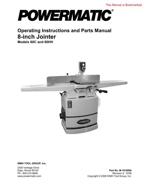
<strong>Operating</strong> <strong>Instructions</strong> and <strong>Parts</strong> <strong>Manual</strong><br />
8-<strong>inch</strong> <strong>Jointer</strong><br />
Models 60C and 60HH<br />
WMH TOOL GROUP, Inc.<br />
2420 Vantage Drive<br />
Elgin, Illinois 60124 Part No. M-1610084<br />
Ph.: 800-274-6848 Revision A 10/08<br />
www.powermatic.com Copyright © 2008 WMH Tool Group, Inc.
Warranty and Service<br />
WMH Tool Group, Inc., warrants every product it sells. If one of our tools needs service or repair, one of our Authorized Service<br />
Centers located throughout the United States can give you quick service. In most cases, any of these WMH Tool Group<br />
Authorized Service Centers can authorize warranty repair, assist you in obtaining parts, or perform routine maintenance and<br />
major repair on your POWERMATIC ® tools. For the name of an Authorized Service Center in your area call 1-800-274-6848.<br />
MORE INFORMATION<br />
WMH Tool Group is consistently adding new products to the line. For complete, up-to-date product information, check with your<br />
local WMH Tool Group distributor, or visit powermatic.com.<br />
WARRANTY<br />
POWERMATIC products carry a limited warranty which varies in duration based upon the product.<br />
WHAT IS COVERED?<br />
This warranty covers any defects in workmanship or materials subject to the exceptions stated below. Cutting tools, abrasives<br />
and other consumables are excluded from warranty coverage.<br />
WHO IS COVERED?<br />
This warranty covers only the initial purchaser of the product.<br />
WHAT IS THE PERIOD OF COVERAGE?<br />
The general POWERMATIC warranty lasts for the time period specified in the product literature of each product.<br />
WHAT IS NOT COVERED?<br />
The Five Year Warranty does not cover products used for commercial, industrial or educational purposes. Products with a Five<br />
Year Warranty that are used for commercial, industrial or education purposes revert to a One Year Warranty. This warranty does<br />
not cover defects due directly or indirectly to misuse, abuse, negligence or accidents, normal wear-and-tear, improper repair or<br />
alterations, or lack of maintenance.<br />
HOW TO GET SERVICE<br />
The product or part must be returned for examination, postage prepaid, to a location designated by us. For the name of the<br />
location nearest you, please call 1-800-274-6848.<br />
You must provide proof of initial purchase date and an explanation of the complaint must accompany the merchandise. If our<br />
inspection discloses a defect, we will repair or replace the product, or refund the purchase price, at our option.<br />
We will return the repaired product or replacement at our expense unless it is determined by us that there is no defect, or that the<br />
defect resulted from causes not within the scope of our warranty in which case we will, at your direction, dispose of or return the<br />
product. In the event you choose to have the product returned, you will be responsible for the handling and shipping costs of the<br />
return.<br />
HOW STATE LAW APPLIES<br />
This warranty gives you specific legal rights; you may also have other rights which vary from state to state.<br />
LIMITATIONS ON THIS WARRANTY<br />
WMH TOOL GROUP LIMITS ALL IMPLIED WARRANTIES TO THE PERIOD OF THE LIMITED WARRANTY FOR EACH<br />
PRODUCT. EXCEPT AS STATED HEREIN, ANY IMPLIED WARRANTIES OR MERCHANTABILITY AND FITNESS ARE<br />
EXCLUDED. SOME STATES DO NOT ALLOW LIMITATIONS ON HOW LONG THE IMPLIED WARRANTY LASTS, SO THE<br />
ABOVE LIMITATION MAY NOT APPLY TO YOU.<br />
WMH TOOL GROUP SHALL IN NO EVENT BE LIABLE FOR DEATH, INJURIES TO PERSONS OR PROPERTY, OR FOR<br />
INCIDENTAL, CONTINGENT, SPECIAL, OR CONSEQUENTIAL DAMAGES ARISING FROM THE USE OF OUR PRODUCTS.<br />
SOME STATES DO NOT ALLOW THE EXCLUSION OR LIMITATION OF INCIDENTAL OR CONSEQUENTIAL DAMAGES, SO<br />
THE ABOVE LIMITATION OR EXCLUSION MAY NOT APPLY TO YOU.<br />
WMH Tool Group sells through distributors only. The specifications in WMH catalogs are given as general information and are<br />
not binding. Members of WMH Tool Group reserve the right to effect at any time, without prior notice, those alterations to parts,<br />
fittings, and accessory equipment which they may deem necessary for any reason whatsoever.<br />
2
Table of Contents<br />
Warranty and Service ..............................................................................................................................2<br />
Table of Contents ....................................................................................................................................3<br />
Warning...................................................................................................................................................4<br />
Introduction .............................................................................................................................................6<br />
Specifications ..........................................................................................................................................6<br />
Features and Terminology - 60C and 60HH <strong>Jointer</strong>s................................................................................7<br />
Unpacking ...............................................................................................................................................8<br />
Assembly ................................................................................................................................................9<br />
Assembling <strong>Jointer</strong> to Stand.................................................................................................................9<br />
Cutterhead Guard ................................................................................................................................9<br />
Aligning Pulleys.................................................................................................................................. 10<br />
Installing Drive Belt ............................................................................................................................ 10<br />
Installing Belt Guard and Door............................................................................................................ 11<br />
Installing Switch Arm.......................................................................................................................... 11<br />
Installing Dust Chute.......................................................................................................................... 11<br />
Installing Fence Handwheel ............................................................................................................... 12<br />
Knife Gauge Assembly (model 60C only) ........................................................................................... 12<br />
Storing the Push Blocks ..................................................................................................................... 12<br />
Electrical Connections ........................................................................................................................... 12<br />
Extension Cords................................................................................................................................. 14<br />
Adjustments .......................................................................................................................................... 14<br />
Installing and Adjusting Knives (Straight Cutterhead only) .................................................................. 14<br />
Replacing and Rotating Knife Inserts (Helical Cutterhead Only).......................................................... 16<br />
Leveling Tables.................................................................................................................................. 17<br />
Adjusting Depth of Cut ....................................................................................................................... 18<br />
Infeed Table Travel Limiter................................................................................................................. 18<br />
Setting Outfeed Table ........................................................................................................................ 18<br />
Spring Cutting.................................................................................................................................... 19<br />
Fence Movement ............................................................................................................................... 19<br />
Fence Stops....................................................................................................................................... 20<br />
<strong>Operating</strong> Controls ................................................................................................................................ 21<br />
Basic <strong>Jointer</strong> Operation ......................................................................................................................... 22<br />
Jointing Short or Thin Work................................................................................................................ 22<br />
Direction of Grain............................................................................................................................... 22<br />
Hand Placement ................................................................................................................................22<br />
Surfacing ........................................................................................................................................... 22<br />
Jointing Warped Surfaces .................................................................................................................. 23<br />
Edge Jointing..................................................................................................................................... 23<br />
Beveling............................................................................................................................................. 23<br />
Skewing (Shear Cutting) .................................................................................................................... 24<br />
Taper Cuts......................................................................................................................................... 24<br />
Rabbeting .......................................................................................................................................... 25<br />
Maintenance.......................................................................................................................................... 25<br />
Sharpening Knives (model 60C only) ................................................................................................. 26<br />
Cutterhead Maintenance.................................................................................................................... 26<br />
Table Removal................................................................................................................................... 27<br />
Troubleshooting – Mechanical and Electrical Problems.......................................................................... 28<br />
Troubleshooting – <strong>Operating</strong> Problems.................................................................................................. 30<br />
Replacement <strong>Parts</strong>................................................................................................................................ 31<br />
<strong>Parts</strong> List: Base Assembly (60C and 60HH) ....................................................................................... 31<br />
Base Assembly (60C and 60HH)........................................................................................................ 33<br />
<strong>Parts</strong> List: Fence Assembly (60C and 60HH)...................................................................................... 34<br />
Fence Assembly (60C and 60HH) ...................................................................................................... 35<br />
<strong>Parts</strong> List: Straight Cutterhead Assembly (60C only)........................................................................... 36<br />
<strong>Parts</strong> List: Helical Cutterhead Assembly (60HH only).......................................................................... 37<br />
<strong>Parts</strong> List: Stand Assembly (60C and 60HH) ...................................................................................... 38<br />
Electrical Connections – Single Phase, 230 Volt .................................................................................... 40<br />
Electrical Connections – 3 Phase, 230 Volt............................................................................................ 41<br />
Electrical Connections – 3 Phase, 460 Volt............................................................................................ 42<br />
3
Warning<br />
1. Read and understand the entire owner’s manual before attempting assembly or operation.<br />
2. Read and understand the warnings posted on the machine and in this manual. Failure to comply with<br />
all of these warnings may cause serious injury.<br />
3. Replace the warning labels if they become obscured or removed.<br />
4. This jointer is designed and intended for use by properly trained and experienced personnel only. If<br />
you are not familiar with the proper and safe operation of a jointer, do not use until proper training and<br />
knowledge have been obtained.<br />
5. Do not use this jointer for other than its intended use. If used for other purposes, WMH Tool Group,<br />
Inc. disclaims any real or implied warranty and holds itself harmless from any injury that may result<br />
from that use.<br />
6. Always wear approved safety glasses/face shields while using this jointer. Everyday eyeglasses only<br />
have impact resistant lenses; they are not safety glasses.<br />
7. Before operating this jointer, remove tie, rings, watches and other jewelry, and roll sleeves up past<br />
the elbows. Remove all loose clothing and confine long hair. Non-slip footwear or anti-skid floor strips<br />
are recommended. Do not wear gloves.<br />
8. Wear ear protectors (plugs or muffs) during extended periods of operation.<br />
9. Some dust created by power sanding, sawing, grinding, drilling and other construction activities<br />
contains chemicals known to cause cancer, birth defects or other reproductive harm. Some examples<br />
of these chemicals are:<br />
• Lead from lead based paint.<br />
• Crystalline silica from bricks, cement and other masonry products.<br />
• Arsenic and chromium from chemically treated lumber.<br />
Your risk of exposure varies, depending on how often you do this type of work. To reduce your<br />
exposure to these chemicals, work in a well-ventilated area and work with approved safety<br />
equipment, such as face or dust masks that are specifically designed to filter out microscopic<br />
particles.<br />
10. Do not operate this machine while tired or under the influence of drugs, alcohol or any medication.<br />
11. Make certain the switch is in the OFF position before connecting the machine to the power supply.<br />
12. Make certain the machine is properly grounded.<br />
13. Make all machine adjustments or maintenance with the machine unplugged from the power source. A<br />
machine under repair should be RED TAGGED to show that it should not be used until maintenance<br />
is complete.<br />
14. Remove adjusting keys and wrenches. Form a habit of checking to see that keys and adjusting<br />
wrenches are removed from the machine before turning it on.<br />
15. Keep safety guards in place at all times when the machine is in use. If removed for maintenance<br />
purposes, use extreme caution and replace the guards immediately after maintenance is complete.<br />
16. Check damaged parts. Before further use of the machine, a guard or other part that is damaged<br />
should be carefully checked to determine that it will operate properly and perform its intended<br />
function. Check for alignment of moving parts, binding of moving parts, breakage of parts, mounting<br />
and any other conditions that may affect its operation. A guard or other part that is damaged should<br />
be properly repaired or replaced.<br />
17. Provide for adequate space surrounding work area and non-glare, overhead lighting.<br />
18. Keep the floor around the machine clean and free of scrap material, oil and grease.<br />
19. Keep visitors a safe distance from the work area. Keep children away.<br />
20. Make your workshop child proof with padlocks, master switches or by removing starter keys.<br />
4
21. Give your work undivided attention. Looking around, carrying on a conversation and “horse-play” are<br />
careless acts that can result in serious injury.<br />
22. Maintain a balanced stance at all times so that you do not fall or lean against the cutterhead or other<br />
moving parts. Do not overreach or use excessive force to perform any machine operation.<br />
23. Use the right tool at the correct speed and feed rate. Do not force a tool or attachment to do a job for<br />
which it was not designed. The right tool will do the job better and more safely.<br />
24. Use recommended accessories; improper accessories may be hazardous.<br />
25. Maintain tools with care. Keep knives and knife inserts sharp and clean for the best and safest<br />
performance. Follow instructions for lubricating and changing accessories.<br />
26. Remove loose items and unnecessary work pieces from the area before starting the machine.<br />
27. Turn off the machine and disconnect from power before cleaning. Use a brush or compressed air to<br />
remove chips or debris — do not use your hands.<br />
28. Do not stand on the machine. Serious injury could occur if the machine tips over.<br />
29. Never leave the machine running unattended. Turn the power off and do not leave the machine until it<br />
comes to a complete stop.<br />
30. When working a piece of wood on the jointer, follow the 3-<strong>inch</strong> radius rule: The hands must never be<br />
closer than 3 <strong>inch</strong>es to the cutterhead.<br />
31. Always use a hold-down or push block when surfacing stock less than 12 <strong>inch</strong>es long, or 3 <strong>inch</strong>es<br />
wide, or 3 <strong>inch</strong>es thick.<br />
32. Do not perform jointing operations on material shorter than 8 <strong>inch</strong>es in length, narrower than 3/4<br />
<strong>inch</strong>es, or less than 1/4 <strong>inch</strong> thick.<br />
33. Do not make cuts deeper than 1/8 <strong>inch</strong> to avoid overloading the machine and to minimize chance of<br />
kickback.<br />
34. Never apply pressure to stock directly over the cutterhead. This may result in the stock tipping into<br />
the cutterhead along with the operator’s fingers. Position hands away from extreme ends of stock,<br />
and push through with a smooth, even motion. Never back workpiece toward the infeed table.<br />
35. “Pull-out” and the danger of kicked back stock can occur when the workpiece has knots, holes or<br />
foreign materials such as nails. It can also occur when the stock is fed against the grain. The grain<br />
should run in the same direction you are cutting. Before attempting to joint or plane, each workpiece<br />
must be carefully examined for stock condition and grain orientation.<br />
NOTE: At certain times it may be necessary to plane against the grain when working with a swirl grain<br />
wood or burl. With this type of work the operator must use a lesser depth of cut and a slow rate of<br />
feed.<br />
Familiarize yourself with the following safety notices used in this manual:<br />
This means that if precautions are not heeded, it may result in minor injury and/or<br />
possible machine damage.<br />
fatal injury.<br />
This means that if precautions are not heeded, it may result in serious or possibly even<br />
5
Introduction<br />
This manual is provided by WMH Tool Group, Inc. covering the safe operation and maintenance<br />
procedures for a Powermatic Model 60C or 60HH <strong>Jointer</strong>. This manual contains instructions on<br />
installation, safety precautions, general operating procedures, maintenance instructions and parts<br />
breakdown. This machine has been designed and constructed to provide years of trouble free operation if<br />
used in accordance with instructions set forth in this manual. If there are any questions or comments,<br />
please contact either your local supplier or WMH Tool Group. WMH Tool Group can also be reached at<br />
our web site: www.wmhtoolgroup.com.<br />
Specifications<br />
Model Number.............................................................................. 60C............................................. 60HH<br />
Stock Numbers:<br />
2HP 1PH 230V ..........................................................1610084K...................................... 1610086K<br />
3HP 3PH 230/460V (prewired 230V).........................1610085K...................................... 1610087K<br />
Maximum depth of cut (in.) .............................................................1/2................................................. 1/2<br />
Maximum rabbeting cut (in.)............................................................1/2................................................. 1/2<br />
Cutterhead style ................................................. straight with 3 knives....... helical w/ 54 four-sided inserts<br />
Knife size (LxWxT)(in.) .................................................8 x 11/16 x 1/8.......................... 0.59 x 0.59 x 0.10<br />
Cutterhead speed (RPM) .............................................................7000.............................................. 7000<br />
Knife cuts per minute................................................................21,000.................................not applicable<br />
Table size (LxH)(in.) ............................................................73 x 8-1/2.......................................73 x 8-1/2<br />
Infeed table length (in.) ..............................................................35-1/4............................................ 35-1/4<br />
Outfeed table length (in.) ...........................................................35-1/2............................................ 35-1/2<br />
Fence size (LxH)(in.) ...........................................................38 x 4-3/4.......................................38 x 4-3/4<br />
Fence tilt (deg.) ...................................................................45 and 90.......................................45 and 90<br />
Fence positive stops (deg.)......................45 forward, 90, 45 backward.......... 45 forward, 90, 45 backward<br />
Dust port diameter (in.)..................................................................... 4.................................................... 4<br />
Sound rating @ 20” (dB)..................................................................93.................................................. 92<br />
Height, floor to outfeed table (in.).....................................................32.................................................. 32<br />
Footprint of cabinet (LxW)(in.)..................................................24 x 17...........................................24 x 17<br />
Overall size (LxWxH)(in.)................................................. 73 x 25 x 46................................... 73 x 25 x 46<br />
Overall height of jointer without stand (in.) .................................13-1/2............................................. 13-12<br />
Weights:<br />
<strong>Jointer</strong> (Net/Shipping)(lbs.) ..............................................295/363..........................................297/366<br />
Stand, 1PH (Net/Shipping)(lbs.) .......................................114/119..........................................114/119<br />
Stand, 3PH (Net/Shipping)(lbs.) .......................................118/123..........................................118/123<br />
The above specifications were current at the time this manual was published, but because of our policy<br />
of continuous improvement, WMH Tool Group, Inc. reserves the right to change specifications at any time<br />
and without prior notice, without incurring obligations.<br />
Read and understand the entire contents of this manual before attempting set-up<br />
or operation! Failure to comply may cause serious injury.<br />
6
Features and Terminology - 60C and 60HH <strong>Jointer</strong>s<br />
Figure 1<br />
7
Unpacking<br />
Open shipping cartons and check for shipping<br />
damage. Report any damage immediately to<br />
your distributor and shipping agent. Do not<br />
discard any shipping material until the <strong>Jointer</strong> is<br />
assembled and running properly.<br />
Compare the contents of your cartons with the<br />
following parts list to make sure all parts are<br />
intact. Missing parts, if any, should be reported<br />
to your distributor. Read the instruction manual<br />
thoroughly for assembly, maintenance and<br />
safety instructions.<br />
Contents of the Shipping Container<br />
The following are included with both straight and<br />
helical cutterhead models<br />
(see Figures 2, 3, 4):<br />
1 <strong>Jointer</strong> Assembly (A)<br />
1 Stand Assembly (B)<br />
1 Switch Arm (C)<br />
1 Dust Chute (D)<br />
1 Drive Belt (E)<br />
1 Door (F)<br />
2 Push Blocks (G)<br />
1 Handwheel (H)<br />
1 Cutterhead Guard (J)<br />
2 Open End Wrenches, 12/14, 8/10mm (K)<br />
1 Hex (Allen) Wrenches, 3mm, 6mm (L)<br />
1 Screwdriver (M)<br />
1 Hardware Bag containing:<br />
3 Carriage Bolts, 3/8”-16 x 2-3/8” (AA)<br />
6 Flat Washers, 3/8” (BB)<br />
3 Lock Washers, 3/8” (CC)<br />
3 Hex Nuts, 3/8” (DD)<br />
4 Socket Head Cap Screws, 5/16”-18x3/4”<br />
(EE)<br />
4 Flat Washers, 5/16” (FF)<br />
4 Lock Washers, 5/16” (GG)<br />
4 Pan Head Screws, 1/4”-20 x 1/2” (HH)<br />
4 Flat Washers, 1/4” (JJ)<br />
2 Pan Head Screws, M6 x 12 (KK)<br />
2 Flat Washers, M6 (LL)<br />
1 Owner's <strong>Manual</strong> (not shown)<br />
1 Warranty Card (not shown)<br />
Included with straight cutterhead models (60C)<br />
only:<br />
1 Knife Setting Gauge Assembly (N)<br />
Included with helical cutterhead models (60HH)<br />
only (see Figure 5):<br />
2 Star Point Screwdrivers (O)<br />
5 Knife Inserts (P)<br />
10 Knife Insert Screws (R)<br />
8<br />
Figure 2<br />
Figure 3<br />
Figure 4<br />
Figure 5 (helical cutterhead only)
Assembly<br />
Exposed metal surfaces, such as the table and<br />
fence, have been given a protective coating at<br />
the factory. This coating should be removed with<br />
a soft cloth and solvent (such as mineral spirits)<br />
once the machine has been assembled. Do not<br />
use an abrasive pad as it may scratch the<br />
exposed surfaces.<br />
NOTE: If any procedure described herein needs<br />
further clarification, consult the assembly<br />
drawings at the back of this manual.<br />
Tools required for assembly:<br />
3mm and 6mm hex (Allen) wrenches<br />
17mm, 14mm, (two)12mm open-end wrenches<br />
screwdriver<br />
Assembling <strong>Jointer</strong> to Stand<br />
Refer to Figure 6.<br />
1. Locate the stand on a level floor. If desired,<br />
the stand can be secured to the floor using<br />
two anchor bolts (not provided) through the<br />
holes inside the bottom of the stand. If using<br />
an optional mobile base, be sure to lock the<br />
wheels before assembling, operating or<br />
adjusting the jointer.<br />
The jointer is very heavy.<br />
Exercise proper caution when lifting it.<br />
2. Use a hoist or forklift with straps, to lift the<br />
jointer onto the stand. (The front of the<br />
jointer should face the same direction as<br />
curved front of the stand.)<br />
3. Shift the jointer atop the stand until the 3hole<br />
pattern aligns in jointer base and stand.<br />
4. Secure jointer base to stand with three 3/8”-<br />
16 x 2-3/8” carriage bolts (AA), six 3/8” flat<br />
washers (BB), three 3/8” lock washers (CC)<br />
and three 3/8” hex nuts (DD). (Note: On the<br />
left hand hole, it may be easier to insert the<br />
carriage bolt from beneath as shown.) Only<br />
finger tighten bolts until all three are<br />
properly inserted; then fully tighten the hex<br />
nuts with a 14mm wrench and a 17mm<br />
wrench on the heads of the screws.<br />
Cutterhead Guard<br />
Place the post of the cutterhead guard (J, Figure<br />
6) into the hole on the rabbeting ledge as<br />
shown. (Always use caution when working<br />
near the cutterhead knives!) Rotate the<br />
locking handle until it tightens into the groove on<br />
the cutterhead guard post.<br />
9<br />
Figure 6
The guard is spring tensioned. When mounted,<br />
it must have enough tension to completely cover<br />
the cutterhead, and press firmly against the<br />
fence. Test the tension by swinging the guard<br />
away from the fence and then releasing it. The<br />
guard should snap back to the fence.<br />
NOTE: The guard must operate freely and must<br />
not drag on the rabbeting ledge or infeed table.<br />
If dragging occurs, check that the locking handle<br />
(Figure 6) is tight. If guard still drags, the guard<br />
assembly may need adjustment or replacement.<br />
Removing Guard:<br />
Some adjustment procedures, and rabbeting<br />
operations, will require removal of the guard.<br />
Loosen handle on rabbet ledge and vertically lift<br />
guard out of the hole.<br />
Aligning Pulleys<br />
Check that the motor pulley and cutterhead<br />
pulley are aligned; this will keep the belt vertical<br />
and help prevent excess wear on it. If<br />
adjustment is necessary, loosen the set screws<br />
in the motor pulley using a hex wrench, and<br />
slide the pulley as needed until alignment is<br />
achieved. Re-tighten set screws.<br />
Installing Drive Belt<br />
Refer to Figure 7.<br />
1. Remove the belt guard (shown in Figure 9).<br />
2. Place one end of the belt through the<br />
opening in the stand and into the groove of<br />
the cutterhead pulley.<br />
3. Reach through the dust chute opening in the<br />
side of the stand with a 12mm wrench, and<br />
keep the motor mount screw heads<br />
stationary, while loosening the hex nuts with<br />
a second 12mm wrench from inside the<br />
stand (Figure 7).<br />
4. Lift up on the motor to provide slack, and<br />
place the lower end of the drive belt into the<br />
motor pulley groove.<br />
5. Let the motor slide back down and push<br />
down on it until the belt is properly<br />
tensioned. NOTE: There should be only<br />
moderate deflection, usually about ½”, in the<br />
belt midway between the pulleys when<br />
using light finger pressure (Figure 8).<br />
6. Tighten the four hex nuts on the motor<br />
mount screws (Figure 7).<br />
10<br />
Figure 7<br />
Figure 8
Installing Belt Guard and Door<br />
Refer to Figure 9.<br />
Mount the belt guard over the shaft as shown,<br />
and install the knob to secure it in place.<br />
Set the lip of the door over the bottom edge of<br />
the stand opening. Rotate the door knob to hold<br />
the door to the stand.<br />
NOTE: When the jointer is being operated, the<br />
two M6 pan head screws (KK) and M6 flat<br />
washers (LL) should be installed to fully secure<br />
the door. At this moment, however, leave these<br />
screws off until the switch has been installed.<br />
Installing Switch Arm<br />
Refer to Figure 10.<br />
1. Align the holes of the switch arm with the<br />
holes on the jointer stand, while slipping the<br />
electrical cord down through the larger hole<br />
in the stand.<br />
2. Secure the switch arm with four 5/16”-18 x<br />
3/4” socket head cap screws (EE), four<br />
5/16” lock washers (GG), and four 5/16” flat<br />
washers (FF), using a 6mm hex wrench.<br />
3. Open the stand door, and join the<br />
connectors of the switch cord and motor<br />
cord, as shown in the detail in Figure 10.<br />
Installing Dust Chute<br />
Refer to Figure 11.<br />
It is strongly recommended that a dust collection<br />
system (not provided) be connected to the<br />
jointer. It will help keep your shop clean, and<br />
reduce the risk of health problems due to wood<br />
dust. The dust collector should have sufficient<br />
capacity for this size jointer. Visit our website at<br />
www.powermatic.com to see a range of<br />
available dust collection units.<br />
Place the dust chute over the opening in the<br />
jointer stand, and secure with four 1/4”-20 x 1/2”<br />
pan head screws (HH) and four 1/4” flat washers<br />
(JJ).<br />
Connect a suitable dust collection hose to the<br />
dust chute on the jointer and secure it with a<br />
hose clamp. NOTE: Dryer vent hose is not<br />
acceptable for this purpose.<br />
11<br />
Figure 9<br />
Figure 10<br />
Figure 11<br />
(hose and clamp not provided)
Installing Fence Handwheel<br />
Refer to Figure 12.<br />
Install the handwheel (H) onto the shaft, and<br />
tighten the set screw with a 3mm hex wrench.<br />
Knife Gauge Assembly (model 60C only)<br />
Refer to Figure 13.<br />
The knife gauge assembly consists of a bar, two<br />
end pieces and two e-clips. Slide the end pieces<br />
onto the ends of the bar as shown, and use a<br />
pliers to push the e-clips into the grooves on the<br />
bar.<br />
Storing the Push Blocks<br />
The two provided push blocks have a magnetic<br />
base – you can attach them to the jointer stand<br />
or any metallic surface, to keep them within<br />
easy reach.<br />
Electrical Connections<br />
Electrical connections must<br />
be made by a qualified electrician in<br />
compliance with all relevant codes. This<br />
machine must be properly grounded to help<br />
prevent electrical shock and possible fatal<br />
injury.<br />
The <strong>Jointer</strong> is equipped with either a single<br />
phase, 230 volt motor; or a three phase,<br />
230/460 volt motor.<br />
The single phase unit is factory wired for 230<br />
volts. You may either install a UL/CSA listed<br />
plug suitable for 230 volt operation, or “hardwire”<br />
the jointer directly to a service panel. It is<br />
recommended that the single phase jointer be<br />
connected to a dedicated, minimum 20 amp<br />
circuit with a 20 amp circuit breaker or time<br />
delay fuse. Local codes take precedence over<br />
recommendations.<br />
The three phase motor is pre-wired for 230 volt.<br />
It may be re-connected for 460 volts by<br />
changing the connections as illustrated in the<br />
diagram in the starter box (see “Converting from<br />
230 Volt to 460 Volt”). You may either install a<br />
UL/CSA listed plug suitable for the specific<br />
voltage, or “hard-wire” the jointer directly to a<br />
service panel. It is recommended that the three<br />
phase jointer, when operated at 230 volts, be<br />
connected to a dedicated, minimum 20 amp<br />
circuit with a 20 amp circuit breaker or time<br />
delay fuse. When operated at 460 volts,<br />
connect the jointer to a dedicated, minimum 15<br />
amp circuit with a 15 amp circuit breaker or time<br />
delay fuse. Local codes take precedence over<br />
recommendations.<br />
12<br />
Figure 12<br />
Figure 13<br />
(model 60C only)
If the jointer is to be hard-wired to a panel, make<br />
sure a disconnect is available for the operator.<br />
During hard-wiring of the machine, make sure<br />
the fuses have been removed or the breakers<br />
have been tripped in the circuit to which the<br />
jointer will be connected. Place a warning<br />
placard on the fuse holder or circuit breaker to<br />
prevent it being turned on while the machine is<br />
being wired.<br />
Grounding <strong>Instructions</strong><br />
This machine must be grounded. In the event of<br />
a malfunction or breakdown, grounding provides<br />
a path of least resistance for electric current to<br />
reduce the risk of electric shock.<br />
Improper connection of the equipmentgrounding<br />
conductor can result in a risk of<br />
electric shock. The conductor with insulation<br />
having an outer surface that is green with or<br />
without yellow stripes, is the equipmentgrounding<br />
conductor. If repair or replacement of<br />
the electric cord or plug is necessary, do not<br />
connect the equipment-grounding conductor to a<br />
live terminal.<br />
Check with a qualified electrician or service<br />
personnel if the grounding instructions are not<br />
completely understood, or if in doubt as to<br />
whether the tool is properly grounded. Repair or<br />
replace a damaged or worn cord immediately.<br />
IMPORTANT: Make sure the electrical<br />
characteristics listed on the motor nameplate<br />
match those of the power source, and make<br />
sure the circuit on which the jointer will be used<br />
is properly fused and that the wire size is<br />
correct.<br />
Converting from 230 Volt to 460 Volt<br />
(Three Phase Only)<br />
Refer to Figure 14.<br />
Consult the wiring diagram inside the starter box<br />
cover. A similar diagram is also included at the<br />
back of this manual. The <strong>Jointer</strong> must comply<br />
with all local and national codes after being<br />
wired.<br />
1. Remove the starter box cover and adjust the<br />
dial on the overload relay as close as<br />
possible to the amperage of the motor at<br />
460V, as listed on the jointer’s motor plate.<br />
2. Move the fuse from the 230V slot to the<br />
460V slot.<br />
3. Re-connect the incoming leads to the motor<br />
in accordance with 460 volt operation, as<br />
shown in the wiring diagram.<br />
4. If using a plug, install a proper UL/CSA<br />
listed plug suitable for 460 volt operation.<br />
13<br />
Figure 14<br />
(230V to 460V conversion)
Three-Phase Test Run<br />
On the three-phase unit, after wiring has been<br />
completed, you should check that the incoming<br />
leads have been connected properly:<br />
1. Connect machine to power source and<br />
press the start button. Make sure cutterhead<br />
is clear of all obstructions! (See page 21 for<br />
more detailed instructions on the switch.)<br />
2. The cutterhead should rotate clockwise as<br />
viewed from the front of the machine. If the<br />
cutterhead rotation is incorrect, press the<br />
stop button and disconnect machine from<br />
power.<br />
3. Switch any two of the three leads to the<br />
motor, then re-connect to power.<br />
Extension Cords<br />
Make sure your extension cord is in good<br />
condition. Always use a cord that is heavy<br />
enough to carry the current your product will<br />
draw; the cord rating must be suitable for the<br />
amperage listed on the machine’s motor plate.<br />
An undersize cord will cause a drop in line<br />
voltage resulting in loss of power and<br />
overheating.<br />
Use the chart in Figure 15 as a general guide in<br />
choosing the correct size cord. If in doubt, use<br />
the next heavier gauge. The smaller the gauge<br />
number, the heavier the cord.<br />
Adjustments<br />
Disconnect machine from<br />
power source before making adjustments.<br />
Tools required for adjustments:<br />
8mm & 12mm wrenches<br />
4mm hex wrench<br />
machinist's protractor or adjustable square<br />
steel straight edge<br />
Installing and Adjusting Knives<br />
(Straight Cutterhead only)<br />
Refer to Figure 16.<br />
Use care when working with<br />
or around sharp knives. Make sure power to<br />
the machine has been disconnected.<br />
When installing new knives, remove only one<br />
knife at a time. Clean the knife slot and install<br />
the new knife. Adjust and snug new knife in<br />
cutterhead before proceeding to next knife.<br />
14<br />
Recommended Gauges (AWG) of Extension Cords<br />
Amps<br />
25<br />
feet<br />
Extension Cord Length *<br />
50<br />
feet<br />
75<br />
feet<br />
100<br />
feet<br />
150<br />
feet<br />
200<br />
feet<br />
< 5 16 16 16 14 12 12<br />
5 to 8 16 16 14 12 10 NR<br />
8 to 12 14 14 12 10 NR NR<br />
12 to 15 12 12 10 10 NR NR<br />
15 to 20 10 10 10 NR NR NR<br />
21 to 30 10 NR NR NR NR NR<br />
*based on limiting the line voltage drop to 5V at 150% of the<br />
rated amperes.<br />
NR: Not Recommended.<br />
Figure 15
1. Disconnect machine from power source.<br />
2. Remove the belt guard so that you can<br />
rotate the cutterhead by turning the motor<br />
pulley or by moving the drive belt. Do not<br />
grab the cutterhead itself to rotate it.<br />
3. Remove the old knives by loosening gib<br />
screws with an 8mm wrench, and allowing<br />
the springs to push the knife upward.<br />
Remove knife and gib.<br />
4. Clean the gib and the knife slot. Sandwich<br />
new knife and gib together and drop into<br />
slot. Make sure the knife is oriented properly<br />
as shown in Figure 16.<br />
IMPORTANT: To position the knives for rabbet<br />
cuts, take a shop scale with 1/32" graduations<br />
and place it against the end of the cutterhead.<br />
See Figure 17. Slide the knife out until it is at the<br />
1/32" mark on the scale; that is, the knife will<br />
now be 1/32" beyond the edge of the<br />
cutterhead. The gib should remain in normal<br />
position, even with the edge of the cutterhead.<br />
This adjustment will ensure that the knife clears<br />
the end of the gib and cutterhead, and has good<br />
contact with the workpiece. (See under “Basic<br />
<strong>Jointer</strong> Operation” for further information on<br />
rabbeting procedures.)<br />
5. The height of the knife in the slot, both for<br />
rabbeting and normal jointer work, must now<br />
be set properly, to ensure correct operation<br />
as well as minimize the hazard of kickback.<br />
Proceed as follows:<br />
6. Rotate the cutterhead (using the belt or<br />
pulley) until the tip of the knife is at the top<br />
of the cutterhead arc. Place the knife setting<br />
gauge (Figure 18) over the cutterhead so<br />
the tip of the knife contacts the center of the<br />
gauge, and all four "feet" of the gauge rest<br />
firmly upon the cutterhead, as the knife is<br />
pushed down into its slot. The gauge will<br />
position the knives at approximately .015"<br />
above the cutterhead. Knife height should<br />
not vary more than .002-.003" across the<br />
length of the cutterhead.<br />
7. Tightening the gib screws should be done in<br />
increments, to prevent any distortion to the<br />
cutterhead or buckling of knives. While<br />
holding the gauge down on one knife, snug<br />
down the five gib screws, beginning with the<br />
center screw and working your way to the<br />
ends. Do not fully tighten yet.<br />
8. Rotate the cutterhead to the next slot and<br />
repeat steps #6 and #7, only making the<br />
knives snug.<br />
9. Repeat for the third knife.<br />
15<br />
Figure 16<br />
(straight cutterhead only)<br />
Figure 17<br />
(straight cutterhead only)<br />
Figure 18<br />
(straight cutterhead only)
10. The tightening process should continue at<br />
least two more times, each time tightening<br />
the screws more on all three knives. On the<br />
third time, they should all be firmly<br />
tightened.<br />
Before starting the jointer,<br />
make sure all gib screws are firmly<br />
tightened. A loose knife thrown from the<br />
cutterhead can cause severe or fatal injury.<br />
11. After replacing knives, the outfeed table<br />
must be checked and adjusted so that it is<br />
level with the high point of the knives. See<br />
“Setting Outfeed Table” on pages 18-19.<br />
Replacing and Rotating Knife Inserts<br />
(Helical Cutterhead Only)<br />
Knife inserts are extremely<br />
sharp; use caution when working with or<br />
around them. Disconnect power.<br />
The knife inserts on the model PJ-882HH are<br />
four-sided. When dull, simply remove each<br />
insert, rotate it 90° for a fresh edge, and reinstall<br />
it.<br />
Two star-point screwdrivers are provided. Insert<br />
one screwdriver into a screw to hold the<br />
cutterhead stationary, while using the other to<br />
loosen and remove a knife insert screw. See<br />
Figure 19. It is advisable to rotate all inserts at<br />
the same time to maintain consistent cutting.<br />
However, if one or more knife inserts develops a<br />
nick, rotate only those inserts that are affected.<br />
Each knife insert has an etched reference mark<br />
so that you can keep track of rotations.<br />
IMPORTANT: When removing or rotating<br />
inserts, clean saw dust from the screw, the<br />
insert, and the cutterhead platform. Dust<br />
accumulation between these elements can<br />
prevent the insert from seating properly, and<br />
may affect the quality of the cut.<br />
Before installing each screw, lightly coat the<br />
screw threads with machine oil and wipe off any<br />
excess.<br />
Securely tighten each screw which holds the<br />
knife inserts before operating the planer!<br />
Make sure all knife insert<br />
screws are tightened securely. Loose inserts<br />
may be propelled at high speed from a<br />
rotating cutterhead, causing injury.<br />
Make sure the outfeed table is set level with the<br />
knife inserts See “Setting Outfeed Table” on<br />
page 18-19.<br />
16<br />
Figure 19<br />
(helical cutterhead only)
Leveling Tables<br />
Refer to Figure 20.<br />
The tables have been leveled with each other<br />
from the factory, but this should be confirmed by<br />
the user, and checked periodically, by placing a<br />
steel straight edge across both tables. If tables<br />
are not level, this may be the result of loose<br />
gibs. Correct as follows:<br />
1. Loosen hex nuts on the gib screws (A) with<br />
a 12mm wrench, then loosen the gib screws<br />
with a 4mm hex wrench. Loosen the table<br />
lock handle (B).<br />
2. Remove the lower hex nut and gib screw (A)<br />
and check screw hole to make sure that<br />
punch mark in the gib is aligned with the<br />
screw hole. If punch mark is not visible, or it<br />
does not line up with screw hole, use a<br />
screwdriver to lightly tap the gib back into<br />
alignment.<br />
3. Re-install the lower gib screw (A) but do not<br />
tighten.<br />
4. Carefully tighten the table lock screw (B).<br />
The table will begin to move toward the<br />
straight edge.<br />
5. When aligned, re-set the gib screws (A) until<br />
tight. If table does not align with straight<br />
edge, use the adjusting arm (C) for the<br />
infeed table, or handwheel (D) for the<br />
outfeed table, until the table is flush with the<br />
straight edge.<br />
6. Tighten the gib screws (A) then back them<br />
off approximately 1/4 turn or until the table<br />
moves freely, and re-set the lock nuts on the<br />
gib screws.<br />
If table will still not line up:<br />
Remove gib screws (A, Figure 20) and table<br />
locking handle (B) and remove gib. Check gib to<br />
see that set screws do not go all the way<br />
through the gib or dimple the opposite side. If<br />
either of these conditions exist, replace with a<br />
new gib.<br />
Also, check to be sure the ways are clean and<br />
free of pitch and sawdust. Lubricate gib and way<br />
with a good grade of non-hardening grease.<br />
Re-install the gib, making certain that the punch<br />
mark lines up with the locking screw holes. Reinstall<br />
gib screws. Repeat steps 3 through 6<br />
above.<br />
17<br />
Figure 20
Adjusting Depth of Cut<br />
Refer to Figure 21.<br />
Depth of cut is determined by the height of the<br />
infeed table relative to the cutterhead. Setting<br />
the infeed table is achieved with both a rapid<br />
adjust and a fine adjust.<br />
Rapid Adjust:<br />
1. Loosen the lock screw (A) and the locking<br />
handle (B).<br />
2. Raise or lower the height adjustment handle<br />
(C) until the scale (D) reads just under the<br />
correct depth of cut.<br />
Fine Adjust:<br />
3. Rotate the locking handle (B) until it is snug,<br />
then fine-tune the adjustment by rotating the<br />
height adjustment handle (C) until the scale<br />
reads exact. (Clockwise raises the table,<br />
counter-clockwise lowers the table.) A full<br />
rotation of the fine adjustment handle equals<br />
1/16" travel of the infeed table.<br />
4. When set, re-tighten lock screw (A).<br />
Periodically check the accuracy of the depth of<br />
cut scale (D, Figure 21) by raising the infeed<br />
table until it is flush with the peak of the<br />
cutterhead arc (using a straight edge across<br />
table and cutterhead). The scale should read<br />
zero depth. If it does not, re-adjust the pointer<br />
above the scale.<br />
Infeed Table Travel Limiter<br />
The infeed table travel limiter (shown in Figure<br />
22) located on the back of the table sets the<br />
upper and lower range for the infeed table<br />
height adjustment. This has been set at the<br />
factory and should not require any adjustments.<br />
Setting Outfeed Table<br />
For accurate work in most jointing operations,<br />
the outfeed table must be exactly level with the<br />
knives at their highest point of revolution.<br />
1. Raise the outfeed table to its highest point,<br />
and place a straight edge across it.<br />
2. Rotate the cutterhead (using the belt or<br />
pulley) until one knife is at its highest point.<br />
3. Loosen the locking handle on the outfeed<br />
table, and rotate the handwheel to lower the<br />
outfeed table until the straight edge contacts<br />
a knife. Rock the cutterhead slightly to make<br />
sure the apex of the knife is contacting the<br />
straight edge. Lock the outfeed table at that<br />
setting.<br />
18<br />
Figure 21<br />
Figure 22<br />
Figure 23<br />
Figure 24
After the outfeed table has been set at the<br />
correct height, it should not be changed except<br />
for special operations or after replacing knives.<br />
Examples of incorrect settings:<br />
If the outfeed table is too high, the finished<br />
surface of the workpiece will be tapered (Figure<br />
23).<br />
If the outfeed table is too low, the work will be<br />
gouged at the end of the cut (Figure 24)<br />
As a final check of the outfeed table adjustment,<br />
run a piece of wood slowly over the knives for 6<br />
to 8 <strong>inch</strong>es; it should rest firmly on both tables<br />
(Figure 25) with no open space under the<br />
finished cut.<br />
Spring Cutting<br />
Refer to Figure 26.<br />
To spring cut, the outfeed table is lowered below<br />
the level of the cutterhead, as shown in Figure<br />
26. Loosen both gib screws (A) on the outfeed<br />
table. Amount of end-drop is controlled with the<br />
table lock screw (B). Tighten handle to reduce<br />
amount of drop. A 1/32" drop usually creates the<br />
ideal concave for spring joints. After completing<br />
a spring cut, return the outfeed table in line with<br />
the cutterhead knives.<br />
Fence Movement<br />
Refer to Figure 27.<br />
To slide the fence forward or backward on the<br />
table, loosen lock handle (A), slide the fence to<br />
desired position and tighten lock handle (A) to<br />
secure fence. Lift up on fence when tilting or<br />
sliding, to prevent scratching the table.<br />
NOTE: The lock handle (A, Figure 27) may be<br />
adjusted to a more convenient position by<br />
loosening the hex nut below the casting (B,<br />
Figure 28), turning the handle to the proper<br />
position, and retightening the hex nut.<br />
To tilt the fence forward:<br />
1. Loosen locking handle (C, Figure 27).<br />
2. Place an angle measuring device on the<br />
table and against the fence. Tilt the fence to<br />
desired angle using the handwheel, and<br />
tighten locking handle (C) to secure the<br />
setting.<br />
To tilt the fence back:<br />
1. Loosen locking handle (C, Figure 27).<br />
2. Flip the stop block (D) out of the way.<br />
3. Tilt the fence to desired angle using the<br />
handwheel, and tighten locking handle (B)<br />
to secure the setting.<br />
19<br />
Figure 25<br />
Figure 26<br />
Figure 27<br />
When the tilted operation is<br />
finished and the fence is returned to 90<br />
degrees, don’t forget to flip the stop block<br />
back to its original position.
Fence Stops<br />
See Figure 29.<br />
Periodically check the 90 degree and 45 degree<br />
tilt accuracy of the fence with an angle<br />
measuring device, such as an adjustable square<br />
or machinist's protractor. If adjustments are<br />
necessary, proceed as follows:<br />
90-degree stop:<br />
1. The 90-degree stop is controlled by the<br />
screw (E, Figure 29).<br />
2. Loosen the locking handle (C) and the hex<br />
nut on the screw (F).<br />
3. Set a square on the table and against the<br />
fence, and rotate the handwheel (G) to<br />
move the fence flush against the square.<br />
Rotate the screw (E) until it contacts the<br />
stop block (D).<br />
4. Tighten the hex nut (F) and the locking<br />
handle (C).<br />
45 degree forward stop:<br />
1. The 45 degree forward stop is controlled by<br />
a screw (H, Figure 29) that is located at the<br />
bottom end of the link bar.<br />
2. Loosen the locking handle (C) and the hex<br />
nut on the screw (H).<br />
3. Set a 45 degree measuring device on the<br />
table and against the fence, and tilt the<br />
fence until it is flush against the device, and<br />
therefore at a 45 degree angle.<br />
4. Rotate the screw (H) until it contacts the<br />
casting below it.<br />
5. Tighten hex nut (H) and locking handle (C).<br />
45 degree back stop:<br />
1. Flip the stop block (D, Figure 29) out of the<br />
way.<br />
2. The 45 degree back stop is controlled by the<br />
screw (J).<br />
3. Loosen the locking handle (C) and the hex<br />
nut on the screw (K).<br />
4. Use an angle measuring device set at 45<br />
degrees beyond the right angle (a total of<br />
135 degrees) and place it on the table and<br />
against the fence. Tilt the fence until it is<br />
flush with the protractor.<br />
5. Rotate the screw (J) to the proper height.<br />
6. Tighten hex nut (K) and locking handle (C).<br />
20<br />
Figure 28<br />
Figure 29
<strong>Operating</strong> Controls<br />
Start/Stop<br />
Power Indicator Light – The start switch has a<br />
power indicator lamp which is on whenever<br />
there is power connected to the <strong>Jointer</strong>, not<br />
just when the <strong>Jointer</strong> is running. Do not assume<br />
that no light means there is no power to the<br />
machine. If the bulb is bad, there will be no<br />
indication. Always check before use.<br />
Do not rely that no light<br />
means no power to the machine. Always<br />
check for power first. Failure to comply may<br />
cause serious injury!<br />
Refer to Figure 30:<br />
Start – Press the green start switch.<br />
When power is connected to the machine, the<br />
green light is always on regardless of whether<br />
the <strong>Jointer</strong> is running or not.<br />
Stop – Press the red switch to stop.<br />
Reset – In the event that the <strong>Jointer</strong> stops<br />
without pressing the stop button, as the result of<br />
a tripped fuse or circuit breaker, etc.:<br />
Press red button to reset main switch.<br />
Press the green button to restart the machine.<br />
Safety Key<br />
The start/stop switch on the <strong>Jointer</strong> comes<br />
equipped with a magnetic safety key. When in<br />
place on the switch as shown in Figure 30, the<br />
magnetic safety key trips a relay which will allow<br />
the machine to start and stop when the<br />
respective switches are pressed. Being<br />
magnetic, the lock can be removed to make the<br />
machine inoperable and can be hidden for safe<br />
storage by attaching it to another magnetic<br />
surface.<br />
When using the <strong>Jointer</strong>, place the key on the<br />
switch cover lining up the arrow on the key with<br />
the REMOVE arrow on the cover. Then rotate<br />
the key so that the arrow lines up with the LOCK<br />
arrow on the cover. This will prevent the safety<br />
key from coming loose from vibration when the<br />
machine is in use.<br />
21<br />
Figure 30
Basic <strong>Jointer</strong> Operation<br />
NOTE: If you are inexperienced at jointing, use<br />
scrap pieces of lumber to check settings and get<br />
the feel of operations before attempting regular<br />
work.<br />
This section briefly discusses general rules as<br />
well as some of the basic cuts using a jointer,<br />
such as surfacing, edging, beveling, skewing,<br />
rabbeting and taper cuts.<br />
Always use cutterhead guard<br />
(except during rabbeting) and keep hands<br />
away from cutterhead.<br />
Jointing Short or Thin Work<br />
When jointing short or thin pieces, use a push<br />
pad or push block to eliminate all danger to the<br />
hands. Two push blocks are included with your<br />
jointer. Many users make their own push blocks<br />
from scrap material to suit the particular job at<br />
hand. Three examples are shown in Figure 31.<br />
Direction of Grain<br />
Avoid feeding work into the jointer against the<br />
grain. This will result in chipped and splintered<br />
edges (Figure 32). Feed with the grain to obtain<br />
a smooth surface (Figure 33).<br />
Hand Placement<br />
At the start of the cut, the left hand holds the<br />
work firmly against the infeed table and fence<br />
while the right hand pushes the work toward the<br />
knives. After the cut is under way, the new<br />
surface rests firmly on the outfeed table. The left<br />
hand should press down on this part, at the<br />
same time maintaining flat contact with the<br />
fence. The right hand presses the work forward<br />
and before the right hand reaches the<br />
cutterhead it is moved to the work on the<br />
outfeed table. Follow the 3 <strong>inch</strong> rule. Never<br />
pass hands directly over the cutterhead.<br />
Surfacing<br />
Jointing the face of stock, or surfacing, is shown<br />
in Figure 34. The use of push blocks or pads will<br />
help ensure against the operator's hands<br />
coming into contact with the cutterhead in the<br />
event of a kickback, or as the trailing end of the<br />
board passes over the cutterhead.<br />
Adjust the infeed table for depth of cut. Cuts of<br />
approximately 1/16" at a time are<br />
recommended, as this allows better control over<br />
the material being surfaced. More passes can<br />
then be made to reach the desired depth.<br />
22<br />
Figure 31<br />
User-made pushblocks<br />
Figure 32<br />
Figure 33
IMPORTANT: When stock is longer than twice<br />
the length of the infeed and outfeed tables, an<br />
assistant or support table must be used to<br />
support the stock.<br />
Always use a hold down or<br />
push block when surfacing short stock or<br />
stock less than 3 <strong>inch</strong>es thick.<br />
Jointing Warped Surfaces<br />
If the wood to be jointed is dished or warped,<br />
take light cuts until the surface is flat. Avoid<br />
forcing such material down against the table;<br />
excessive pressure will spring it while passing<br />
the knives, and it will simply spring back and<br />
remain curved after the cut is completed.<br />
Edge Jointing<br />
This is the most common operation for the<br />
jointer. Set guide fence square with the table.<br />
Depth of cut should be the minimum required to<br />
obtain a straight edge. Do not make cuts deeper<br />
than 1/8" in a single pass. Hold the best face of<br />
the piece firmly against the fence throughout the<br />
feed. See Figure 35.<br />
When edging stock wider than 3 <strong>inch</strong>es, lap the<br />
fingers over the top of the wood, extending them<br />
back over the fence so that the fence casting will<br />
act as a stop for the hands in the event of a<br />
kickback.<br />
Beveling<br />
Never make cuts deeper than 1/16 <strong>inch</strong> when<br />
beveling. Make certain material being beveled is<br />
over 12 <strong>inch</strong>es long, more than 1/4" thick and 1"<br />
wide.<br />
Although the fence may be<br />
tilted in or out for a bevel cut, It is<br />
recommended for safety reasons that the<br />
fence be tilted in toward the operator,<br />
making a cradled cut.<br />
Set fence to desired angle. For stock wider than<br />
3", hold with the fingers close together near the<br />
top of the stock, lapping over the board and<br />
extending over the fence. When beveling<br />
material less than 3" wide, use beveled push<br />
blocks.<br />
23<br />
Figure 34<br />
Figure 35
Skewing (Shear Cutting)<br />
When edging or facing burl or birds-eye maple,<br />
it is not unusual to deface or mar the surface<br />
being finished. This is caused by the cutterhead<br />
knives occasionally cutting against the grain. In<br />
order to prevent the defacing or marring of this<br />
type wood, it is necessary to skew, or angle<br />
finish, the material being worked.<br />
Refer to Figure 36.<br />
1. Release the fence locking handle (A, Figure<br />
36) and remove the hex nut and washer (B)<br />
holding the fence to the fence support.<br />
Remove the fence assembly.<br />
2. Remove the key (C) and the 1/4”-20 x 1/4”<br />
socket head cap screw (D) from the fence<br />
support. (The socket head screw keeps the<br />
non-mar insert from hitting the key.)<br />
3. Position the fence assembly at the desired<br />
angle across the cutterhead.<br />
4. Secure the fence to the support with the hex<br />
nut and washer (B), then tighten the fence<br />
locking handle (A).<br />
When resuming work with normal stock, always<br />
re-install the key and the socket head cap<br />
screw!<br />
Taper Cuts<br />
A useful jointer operation is cutting an edge to a<br />
taper. The method can be used on a wide<br />
variety of work. Tapered legs of furniture are a<br />
common example. Instead of laying the piece on<br />
the infeed table, lower the forward end of the<br />
work onto the outfeed table. Do this very<br />
carefully, as the piece will span the knives, and<br />
they will take a "bite" from the work with a<br />
tendency to kick back unless the piece is firmly<br />
held. Now push the work forward as in ordinary<br />
jointing.<br />
The effect is to plane off all the stock in front of<br />
the knives to increasing depth, leaving a tapered<br />
surface. The ridge left by the knives when<br />
starting the taper may be removed by taking a<br />
very light cut according to the regular method for<br />
jointing, with the infeed table raised to its usual<br />
position.<br />
Practice is required in taper operations, and the<br />
beginner is advised to make trial cuts on waste<br />
material. Taper cuts over part of the length and<br />
a number of other special operations can easily<br />
be done as the operator gains experience.<br />
24<br />
Figure 36
Rabbeting<br />
A rabbet cut requires<br />
removal of the cutter guard. Use extreme<br />
caution and keep hands clear of cutterhead.<br />
Always replace guard immediately after<br />
rabbeting operation is completed.<br />
Refer to Figure 37.<br />
A rabbet is a groove cut along the edge of a<br />
board. Never rabbet a piece of wood less than<br />
12" long. Use push blocks to rabbet cut<br />
whenever possible.<br />
1. Disconnect machine from power source.<br />
2. Set fence for the desired width of the rabbet.<br />
3. Check the width of the rabbet by measuring<br />
the distance from the end of a knife in the<br />
cutterhead to the fence. (See figure 17 to<br />
set knives for rabbeting.)<br />
4. Lower infeed table 1/32" at a time and make<br />
successive cuts until the desired depth of<br />
rabbet has been obtained. NOTE: It is<br />
easier and safer to take a series of shallow<br />
cuts.<br />
When rabbeting long pieces, follow the same<br />
procedure as for surfacing long pieces (refer to<br />
previous “Surfacing” section.)<br />
Maintenance<br />
Disconnect machine from<br />
power source before doing any maintenance.<br />
The table and fence surfaces must be kept<br />
clean and free of rust for best results. Some<br />
users prefer a light coat of paste wax. Another<br />
option is talcum powder applied with a<br />
blackboard eraser rubbed in vigorously once a<br />
week, which will fill casting pores and form a<br />
moisture barrier. Products in aerosol form are<br />
also available in major hardware stores and<br />
supply catalogs. Whatever method is chosen,<br />
the coating should protect the metal and provide<br />
a smooth surface, without staining the wood.<br />
The fence assembly should slide easily over the<br />
fence support. Keep the fence support greased.<br />
The bearings in the cutterhead are sealed and<br />
do not require lubrication.<br />
Gum and pitch which collect on the knives<br />
cause excessive friction as the work continues,<br />
resulting in overheating of the knives, less<br />
efficient cutting, and consequent reduction in the<br />
life of the knives. Use an oven cleaner or gum<br />
and pitch remover to wipe such residue off the<br />
knives.<br />
25<br />
Figure 37
Sharpening Knives (model 60C only)<br />
Knives should be kept sharp. This will contribute<br />
to better stock finish, longer machine life, and<br />
safer operation.<br />
A jointer knife hone provides a simple way to<br />
sharpen straight knives. Hones are available<br />
from many woodworking supply stores. Carefully<br />
read any instructions that accompany the hone.<br />
Use caution and proceed<br />
slowly when sharpening knives. Disconnect<br />
jointer from power source, and wear<br />
approved eye protection.<br />
When finished sharpening knives, they should<br />
be re-set level to the outfeed table. See the<br />
“Installing and Adjusting Knives” section in this<br />
manual.<br />
Knives can usually be whetted several times in<br />
the cutterhead before having to be removed and<br />
re-ground.<br />
TIP: If the jointer is used frequently, keeping a<br />
spare set of knives on hand is recommended.<br />
Extra knives (stock no. 6296046, set of 3) may<br />
be obtained from your Powermatic distributor, or<br />
by calling WMH Tool Group at 1-800-274-6848.<br />
Cutterhead Maintenance<br />
The entire cutterhead assembly may be<br />
removed for bearing replacement or other<br />
maintenance procedures.<br />
1. Disconnect jointer from power source.<br />
2. Remove fence assembly from jointer (see<br />
Figure 36 and accompanying instructions).<br />
3. Loosen motor mounting and push up on<br />
motor to create slack in belt (see page 10)<br />
4. Remove drive belt from cutterhead pulley.<br />
5. Lower both infeed and outfeed tables.<br />
6. Loosen the two socket head cap screws on<br />
the fence support and pivot the fence<br />
support out of the way (see Figure 38).<br />
7. Remove rabbeting ledge by loosening the<br />
two hex cap screws and washers (A, Figure<br />
39).<br />
8. Loosen the two bolts (B, Figure 39) that<br />
secure the cutterhead to the bed – these are<br />
accessed from the underside of the bearing<br />
blocks.<br />
Either remove the knives or<br />
knife inserts from the cutterhead, or wrap<br />
cloths around it to prevent injury.<br />
26<br />
Figure 38<br />
Figure 39
9. Lift cutterhead straight up from base.<br />
10. Remove pulley and both bearing housings.<br />
IMPORTANT: The bearings are press fitted; if<br />
they need replacement, this should be done by<br />
qualified service personnel only.<br />
To re-install cutterhead, reverse the above<br />
procedure. Before re-installing, make sure the<br />
machine's curved seats of the base casting are<br />
free of dirt, dust or grease, to help ensure a tight<br />
fit.<br />
NOTE: Whenever the cutterhead is re-installed<br />
on the jointer, the tables must be leveled in<br />
relationship to it. See the appropriate sections in<br />
this manual.<br />
You may wish to keep an extra cutterhead on<br />
hand to maintain shop productivity.<br />
Table Removal<br />
Should the table(s) ever need to be removed,<br />
such as for gib maintenance or replacement,<br />
proceed as follows:<br />
1. Disconnect jointer from power source.<br />
2. Remove fence assembly except for the<br />
support casting.<br />
3. Remove cutter guard.<br />
4. Lower infeed and outfeed tables and<br />
remove cutterhead.<br />
5. Loosen the gib set screws and table lock<br />
screws.<br />
After gib screws are<br />
loosened, table could suddenly slide down.<br />
6. Remove infeed or outfeed table by sliding<br />
upward.<br />
27
Troubleshooting – Mechanical and Electrical Problems<br />
Trouble Probable Cause Remedy<br />
Machine will not<br />
start/restart or<br />
repeatedly trips<br />
circuit breaker or<br />
blows fuses.<br />
No incoming power.<br />
Overload automatic reset has<br />
not reset.<br />
<strong>Jointer</strong> frequently trips.<br />
Building circuit breaker trips<br />
or fuse blows.<br />
Switch or motor failure (how<br />
to distinguish).<br />
Motor overheated.<br />
Motor failure.<br />
Electrical leads are attached<br />
incorrectly.<br />
28<br />
Verify unit is connected to power, on-button is<br />
pushed in completely, and stop-button is<br />
disengaged.<br />
When jointer overloads on the circuit breaker<br />
built into the motor starter, it takes time for the<br />
machine to cool down before restart. Allow<br />
unit to adequately cool before attempting<br />
restart. If problem persists, check amp setting<br />
on the motor starter inside the electrical<br />
enclosure – it should match the amps on the<br />
motor as indicated on the motor plate.<br />
One cause of overloading trips which are not<br />
electrical in nature is too deep of a cut. The<br />
solution is to take a lighter cut. If too deep a<br />
cut is not the problem, then check the amp<br />
setting on the overload relay. Match the full<br />
load amps on the motor as noted on the<br />
motor plate. If amp setting is correct then<br />
there is probably a loose electrical lead.<br />
Verify that jointer is on a circuit of correct size.<br />
If circuit size is correct, there is probably a<br />
loose electrical lead. Also check amp setting<br />
on motor starter.<br />
Examine motor starter for burned or failed<br />
components. If damage is found, replace<br />
starter. If no visible damage found, have<br />
starter tested.<br />
If you have access to a voltmeter, you can<br />
separate a starter failure from a motor failure<br />
by first, verifying incoming voltage at 220+/-20<br />
and second, checking the voltage between<br />
starter and motor at 220+/-20. If incoming<br />
voltage is incorrect, you have a power supply<br />
problem. If voltage between starter and motor<br />
is incorrect, you have a starter problem. If<br />
voltage between starter and motor is correct,<br />
you have a motor problem.<br />
Clean motor of dust or debris to allow proper<br />
air circulation. Allow motor to cool down<br />
before restarting.<br />
If electric motor is suspect, have it tested by<br />
qualified service personnel. Repair or replace<br />
as needed.<br />
Double check to confirm all electrical<br />
connections are correct. Refer to appropriate<br />
wiring diagrams posted on the machine and<br />
at the back of this manual, to make any<br />
needed corrections.
Trouble Probable Cause Remedy<br />
Machine will not<br />
start/restart or<br />
repeatedly trips<br />
circuit breaker or<br />
blows fuses.<br />
Loose electrical connections.<br />
On/off switch failure.<br />
29<br />
Inspect all motor leads for tightness. Look for<br />
any signs of electrical arcing which would<br />
indicate loose connections or circuit overload.<br />
If the on/off switch is suspect, you have two<br />
options: Have a qualified electrician test the<br />
switch for function, or purchase a new on/off<br />
switch and establish if that was the problem<br />
on changeout.
Troubleshooting – <strong>Operating</strong> Problems<br />
Trouble Probable Cause Remedy<br />
Finished stock is<br />
concave on back<br />
end.<br />
Finished stock is<br />
concave on front end.<br />
Stock has slight bevel<br />
after edge jointing.<br />
Chip out.<br />
Fuzzy, rough, or torn<br />
grain.<br />
Board thickness does<br />
not match depth of<br />
cut scale.<br />
Cutterhead slows<br />
while operating.<br />
“Chatter” marks on<br />
workpiece.<br />
Uneven knife marks<br />
on workpiece.<br />
Knife is higher than outfeed table.<br />
Outfeed table is higher than knife.<br />
30<br />
Raise outfeed table until it aligns with<br />
tip of knife. See pages 18-19.<br />
Lower outfeed table until it aligns with<br />
tip of knife. See pages 18-19.<br />
Fence not perpendicular to table. Square up fence with table.<br />
Cutting against the grain. Cut with the grain whenever possible.<br />
Dull knives/knife inserts.<br />
Sharpen or replace knives.<br />
Rotate knife inserts.<br />
Feeding workpiece too fast. Use slower rate of feed.<br />
Cutting too deeply. Make shallower cuts.<br />
Knots, imperfections in wood.<br />
Inspect wood closely for imperfections;<br />
use different stock if necessary.<br />
Wood has high moisture content. Allow wood to dry or use different stock.<br />
Dull knives/knife inserts.<br />
Sharpen or replace knives.<br />
Rotate knife inserts.<br />
Knives are cutting against grain. Cut with the grain.<br />
Depth of cut scale is incorrect.<br />
Feeding too quickly, or applying too<br />
much pressure to workpiece.<br />
Loosen screw and adjust scale<br />
accordingly.<br />
Feed more slowly, or apply less<br />
pressure to workpiece.<br />
Excessive depth of cut. Reduce depth of cut.<br />
Dull knives/knife inserts.<br />
Knives incorrectly set on straight<br />
cutterhead.<br />
Feeding workpiece too fast.<br />
Knives are nicked, or out of<br />
alignment.<br />
Sharpen or replace knives.<br />
Rotate knife inserts.<br />
Set knives properly using provided knife<br />
setting gauge. Check that knife slots<br />
are clean and free of dust or debris.<br />
Feed workpiece slowly and<br />
consistently.<br />
Straight cutterhead: Replace nicked<br />
knives; align knives properly using<br />
knife-setting gauge. See pages 14-16.<br />
Helical cutterhead: Rotate nicked<br />
inserts. See page 16.
Replacement <strong>Parts</strong><br />
Replacement parts are listed on the following pages. To order parts or reach our service department, call<br />
1-800-274-6848, Monday through Friday (see our website for business hours, www.powermatic.com).<br />
Having the Model Number and Serial Number of your machine available when you call will allow us to<br />
serve you quickly and accurately.<br />
<strong>Parts</strong> List: Base Assembly (60C and 60HH)<br />
Index No. Part No. Description Size Qty<br />
1............... 6296000...................Rear Table ............................................................................................ 1<br />
2............... TS-0267041.............Set Screw...........................................................1/4”-20x3/8”................ 6<br />
3............... 6296001...................Collar .................................................................................................... 1<br />
4............... 6296002...................Bracket.................................................................................................. 1<br />
5............... 6296003...................Key.....................................................................5x5x12mm.................. 1<br />
6............... 6296004...................Lead Screw ........................................................................................... 1<br />
7............... 6296005...................Bracket.................................................................................................. 1<br />
8............... TS-0720091.............Lock Washer ......................................................3/8”............................. 2<br />
9............... TS-0209061.............Cap Screw..........................................................3/8”-16x1-1/4”............. 2<br />
10............. TS-0720111.............Lock Washer ......................................................1/2”............................. 2<br />
11............. 6296009...................Cap Screw..........................................................1/2”-12NCx1-1/2”........ 2<br />
12............. 6296010...................Bolt........................................................................................................ 2<br />
13............. TS-0561021.............Hex Nut..............................................................5/16”-18...................... 9<br />
14............. TS-0267091.............Set Screw...........................................................1/4”-20x1”................... 6<br />
15............. 60B-215...................Base...................................................................................................... 1<br />
16............. 6296013...................Gib ........................................................................................................ 2<br />
17............. TS-0208041.............Socket Head Cap Screw.....................................5/16”-18x3/4”.............. 3<br />
18............. 6296015...................Retaining Ring....................................................ETW-6........................ 3<br />
19............. 6296132...................Bar ........................................................................................................ 1<br />
20............. 6296016...................Bolt........................................................................................................ 1<br />
21............. 6296017...................Shaft ..................................................................................................... 1<br />
22............. 6296018...................Lock Bracket ......................................................................................... 1<br />
23............. 6296019...................Bracket.................................................................................................. 1<br />
24............. 6296020...................Ball........................................................................................................ 2<br />
25............. 6296021...................Shaft ..................................................................................................... 1<br />
26............. 6296022...................Retaining Ring....................................................ETW-12...................... 2<br />
27............. 6296023...................Worm .................................................................................................... 1<br />
28............. 6296024...................Key.....................................................................5x5x20 ....................... 1<br />
29............. 6296025...................Adjusting Base ...................................................................................... 1<br />
30............. TS-0680021.............Flat Washer........................................................1/4”............................. 1<br />
31............. TS-0050031.............Hex Cap Screw ..................................................1/4”-20x3/4”................ 1<br />
32............. 6296029...................Worm Shaft ........................................................................................... 1<br />
33............. 6296028...................Handle................................................................................................... 1<br />
34............. TS-0680021.............Flat Washer........................................................1/4”............................. 2<br />
35............. TS-0207021.............Socket Head Cap Screw.....................................1/4”-20x1/2”................ 6<br />
36............. TS-0720071.............Lock Washer ......................................................1/4”............................. 5<br />
37............. 6296033...................Clamp Knob .......................................................................................... 1<br />
38............. TS-0680061.............Flat Washer........................................................1/2”............................. 1<br />
39............. 6296035...................Lock Plate ............................................................................................. 1<br />
40............. 6296036...................Plate...................................................................................................... 1<br />
41............. 60B-241...................Front Table............................................................................................ 1<br />
42............. 6296038...................Handwheel ............................................................................................ 1<br />
43............. 6296039...................Phillips Pan Head Screw.....................................5/16”-18x1/2”.............. 1<br />
44............. TS-0680041.............Flat Washer........................................................3/8”............................. 1<br />
45............. 60B-245...................Rabbeting Ledge ................................................................................... 1<br />
46............. TS-0680041.............Flat Washer........................................................................................... 3<br />
47............. TS-0060051.............Hex Cap Screw ..................................................3/8”-16x1”................... 2<br />
48............. 6296044...................Pointer................................................................................................... 1<br />
31
49............. TS-081B012.............Phillips Pan Head Screw.....................................#8-32x1/4”.................. 1<br />
50............. 6296056...................Bolt........................................................................................................ 1<br />
51............. 6296057...................Belt Guard............................................................................................. 1<br />
52............. 6296058...................Knob ..................................................................................................... 1<br />
53............. TS-0270091.............Set Screw...........................................................5/16”-18x1”................. 2<br />
54............. 6296061...................Set Block............................................................................................... 1<br />
55............. 6296062...................Bolt........................................................................................................ 1<br />
56............. 6296063...................Collar .................................................................................................... 1<br />
57............. TS-0680031.............Flat Washer........................................................5/16”........................... 6<br />
59............. 6296167...................Depth Scale........................................................................................... 1<br />
60............. VS020500................Rivet...................................................................2x5mm ....................... 4<br />
61............. TS-0267021.............Socket Set Screw ...............................................1/4”-20x1/4”................ 4<br />
62............. 6296151...................Collar .................................................................................................... 2<br />
63............. 60C-263...................Push Block ............................................................................................ 2<br />
64............. TS-0208021.............Socket Head Cap Screw.....................................5/16”-18x1/2”.............. 1<br />
65............. 6296166...................Flat Washer........................................................5/16”x3/4”D ................ 2<br />
66............. TS-0209071.............Socket Head Cap Screw.....................................3/8”-16x1-1/2”............. 2<br />
67............. TS-1550071.............Flat Washer........................................................3/8”x3/4”D .................. 1<br />
68............. 6296089...................Key.....................................................................9.5mmx273mm........... 1<br />
69............. 6296088...................Spring Pin...........................................................4x14mm ..................... 1<br />
70............. 60C-270...................Base Slide............................................................................................. 1<br />
71............. 60B-271...................Stop Handle .......................................................................................... 1<br />
................. 60B-270...................Cutterhead Guard Assembly (Index # 72 thru 77) .................................. 1<br />
72............. 60B-272...................Warning Label ....................................................................................... 1<br />
73............. 60B-273...................Cutterhead Guard.................................................................................. 1<br />
74............. JSG96-223 ..............Retaining Ring....................................................STW-11...................... 1<br />
75............. 60B-275...................Spring.................................................................................................... 1<br />
76............. 60B-276...................Shaft ..................................................................................................... 1<br />
77............. 60B-277...................Spring Pin...........................................................6x36mm ..................... 2<br />
78............. 60C-278...................I.D. Label............................................................1Ph ............................ 1<br />
................. 60C-278A ................I.D. Label............................................................3Ph ............................ 1<br />
................. 60HH-278 ................I.D. Label............................................................1Ph ............................ 1<br />
................. 60HH-278A..............I.D. Label............................................................3Ph ............................ 1<br />
79............. TS-0207021.............Socket Head Cap Screw.....................................1/4”-20x1/4”................ 1<br />
32
Base Assembly (60C and 60HH)<br />
33
<strong>Parts</strong> List: Fence Assembly (60C and 60HH)<br />
Index No. Part No. Description Size Qty<br />
................. PJ882-FA.................Fence Assembly (Index #1 thru 49)..........................................................<br />
1............... PJ882-101 ...............Hand Wheel .......................................................................................... 1<br />
2............... TS-0267021.............Socket Set Screw ...............................................1/4”-20x1/4”................ 3<br />
3............... TS-0207031.............Socket Head Cap Screw.....................................1/4”-20x5/8”................ 4<br />
4............... PJ882-104 ...............Bearing Cover ....................................................................................... 1<br />
5............... PJ882-105 ...............C-Ring................................................................STW-12...................... 2<br />
6............... PJ882-106 ...............Worm Shaft ........................................................................................... 1<br />
7............... BB-6001ZZ ..............Ball Bearing........................................................6001ZZ....................... 2<br />
8............... PJ882-108 ...............Pin......................................................................Ø3x20mm................... 1<br />
9............... TS-0810012.............Round Head Slotted Machine Screw...................#10-24x1/4” ................ 2<br />
10............. TS-0680011.............Flat Washer........................................................3/16”........................... 2<br />
11............. PJ882-111 ...............Pointer................................................................................................... 1<br />
12............. 6285945...................Knob ..................................................................................................... 1<br />
13............. 6296069...................Locking Shaft......................................................................................... 1<br />
14............. 6285944...................Handle Stud .......................................................................................... 1<br />
15............. TS-0207021.............Socket Head Cap Screw.....................................1/4”-20x1/2”................ 1<br />
16............. 6296084...................Bolt........................................................................................................ 1<br />
17............. TS-0680061.............Flat Washer........................................................1/2”............................. 1<br />
18............. PJ882-118 ...............Nylon Nut ...........................................................1/2”-12........................ 1<br />
19............. PJ882-119 ...............Locking Handle...................................................................................... 1<br />
20............. PJ882-120 ...............Bushing ................................................................................................. 1<br />
21............. PJ882-121 ...............Stop Block............................................................................................. 1<br />
22............. PJ882-122 ...............Fence Bracket ....................................................................................... 1<br />
23............. PJ882-123 ...............Worm .................................................................................................... 1<br />
24............. PJ882-124 ...............Retaining Ring....................................................RTW-28...................... 1<br />
25............. TS-0050031.............Hex Cap Screw ..................................................1/4”-20x3/4”................ 1<br />
26............. PJ882-126 ...............Rack...................................................................................................... 1<br />
27............. PJ882-127 ...............Locking Handle Nut ............................................................................... 1<br />
28............. PJ882-128 ...............Locking Link .......................................................................................... 1<br />
29............. TS-0561011.............Hex Nut..............................................................1/4”-20........................ 3<br />
30............. TS-0050051.............Hex Cap Screw ..................................................1/4”-20x1”................... 2<br />
31............. PJ882-131 ...............Safety Plate........................................................................................... 1<br />
32............. TS-081F031.............Phillips Flat Head Machine Screw.......................1/4”-20x1/2”................ 2<br />
33............. 6296070...................Pin......................................................................5mmx50mm ............... 1<br />
34............. TS-0206021.............Socket Head Cap Screw.....................................#10-24x1/2” ................ 5<br />
35............. 6296073...................Screw.................................................................................................... 1<br />
36............. 6296082...................Fence Link............................................................................................. 1<br />
37............. 6285942...................Cone Point Screw.................................................................................. 4<br />
38............. TS-0561031.............Hex Nut..............................................................3/8”-16........................ 4<br />
39............. TS-0720071.............Lock Washer ......................................................1/4”............................. 2<br />
40............. 6285940...................Pivot Stud.............................................................................................. 2<br />
41............. TS-0561052.............Hex Nut..............................................................1/2”-20UNF ................ 2<br />
42............. PJ882-142 ...............Fixed Block............................................................................................ 1<br />
43............. PJ882-143 ...............Fence.................................................................................................... 1<br />
44............. PJ882-144 ...............Insert..................................................................................................... 1<br />
45............. 60B-130...................Caution Label (Setting Knives)............................................................... 1<br />
46............. 60B-129...................Caution Label (Hands Clear).................................................................. 1<br />
47............. PJ882-147 ...............Label (Lock/ Unlock).............................................................................. 1<br />
48............. PJ882-148 ...............Scale Label ........................................................................................... 1<br />
49............. PJ882-333 ...............Spring Pin...........................................................Ø4x25mm................... 1<br />
34
Fence Assembly (60C and 60HH)<br />
35
<strong>Parts</strong> List: Straight Cutterhead Assembly (60C only)<br />
Index No. Part No. Description Size Qty<br />
................. 60B-300...................Cutterhead Assembly (Index # 1 thru 5, and 10 thru 13)......................... 1<br />
1............... 6296046...................Knife...................................................................................................... 3<br />
2............... 6296153...................Knife Gib ............................................................................................... 3<br />
3............... 6296048...................Key.....................................................................5x5x25mm.................. 1<br />
4............... 6296049...................Ball Bearing........................................................6203-2NSE................. 2<br />
5............... 6296050...................Bearing Housing.................................................................................... 2<br />
6............... TS-0267021.............Set Screw...........................................................1/4”-20x1/4”................ 2<br />
7............... 6296051...................Pulley .................................................................................................... 1<br />
8............... 6285853...................Bolt........................................................................................................ 2<br />
9............... TS-0720091.............Lock Washer ......................................................3/8”............................. 2<br />
10............. 6296154...................Square Head Screw ............................................................................ 15<br />
11............. 6296053...................Cutterhead ............................................................................................ 1<br />
12............. 6296054...................Spring.................................................................................................... 6<br />
13............. 6296055...................Flat Head Screw.................................................M5-0.8Px12................ 6<br />
................. 60B-301...................Knife Gauge Assembly (Index # 14, 15, 16) ........................................... 1<br />
14............. 6296155...................Knife Gauge .......................................................................................... 2<br />
15............. 6296156...................Knife Gauge Bar.................................................................................... 1<br />
16............. 6296157...................E-Clip .................................................................ETW-6........................ 2<br />
36
<strong>Parts</strong> List: Helical Cutterhead Assembly (60HH only)<br />
Index No. Part No. Description Size Qty<br />
................. 60HH-CA .................Cutterhead Assembly (Index #1 thru 8).................................................. 1<br />
1............... TS-0267021.............Socket Set Screw ...............................................1/4”-20x1/4”................ 2<br />
2............... 6296051...................Pulley .................................................................................................... 1<br />
3............... 6296050...................Bearing Housing.................................................................................... 2<br />
4............... 6296049...................Ball Bearing........................................................6203-2NSE................. 2<br />
5............... JWP208HH-111.......Knife Insert Screw ..............................................#10-32x1/2” .............. 54<br />
6............... 1791212...................Knife Insert (set of 10) ..................................................................total 54<br />
7............... 6296048...................Key.....................................................................5x5x25mm.................. 1<br />
8............... 60HH-308 ................Helical Cutterhead................................................................................. 1<br />
9............... TS-0720091.............Lock Washer ......................................................3/8”............................. 2<br />
10............. 6285853...................Bolt........................................................................................................ 2<br />
11............. JJ6HH-113...............Star Point Screwdriver (not shown)........................................................ 2<br />
37
<strong>Parts</strong> List: Stand Assembly (60C and 60HH)<br />
Index No. Part No. Description Size Qty<br />
................. 2365025...................60C/60HH Stand Assembly (Index #1 thru 51)....2HP, 1Ph, 230V.......... 1<br />
................. 2365026...................60C/60HH Stand Assembly (Index #1 thru 51)....3HP, 3Ph, 230/460V... 1<br />
1............... 60C-401...................Stand .................................................................................................... 1<br />
2............... 60B-402...................Door ...................................................................................................... 1<br />
3............... 60B-403...................Carriage Bolt ......................................................3/8”-16x2-3/8”............. 3<br />
4............... TS-1550071.............Flat Washer........................................................3/8”............................. 6<br />
5............... TS-1534042.............Phillips Pan Head Machine Screw ......................M6x12 ........................ 2<br />
6............... TS-1550041.............Flat Washer........................................................M6.............................. 2<br />
7............... 6285975...................Screw Knob........................................................................................... 1<br />
8............... 6285976...................Door Lock.............................................................................................. 1<br />
9............... 6285977...................Hex Nut..............................................................3/8”-16........................ 1<br />
10............. 60B-410...................Carriage Bolt ......................................................5/16”-18x3/4”.............. 4<br />
11............. 6285805...................Flat Washer........................................................5/16”........................... 4<br />
12............. VB-A44 ....................V-Belt .................................................................A-44 ........................... 1<br />
13............. 60B-413...................Motor Pulley .......................................................................................... 1<br />
14............. TS-0267021.............Set Screw...........................................................1/4”-20x1/4”................ 2<br />
15............. 60B-415...................Motor..................................................................2HP, 1Ph, 230V.......... 1<br />
................. 60B-415MF..............Motor Fan (not shown)........................................................................... 1<br />
................. 60B-415MFC ...........Motor Fan Cover (not shown) ................................................................ 1<br />
................. 60B-415CS ..............Centrifugal Switch (not shown) .............................................................. 1<br />
................. 60B-415MDC ...........Motor Dustproof Cover (not shown) ....................................................... 1<br />
................. 60B-415CC..............Capacitor Cover (not shown) ................................................................. 2<br />
................. 60B-415SC ..............Starting Capacitor (not shown)............................400MFD, 125VAC ...... 1<br />
................. 60B-415RC..............Running Capacitor (not shown)...........................30uf, 350VAC............. 1<br />
................. 60B-415A.................Motor..................................................................3HP, 3Ph, 230/460V... 1<br />
16............. 6285988...................Lock Washer ......................................................5/16”........................... 4<br />
17............. 6285966...................Hex Nut..............................................................5/16”-18...................... 1<br />
18............. 60B-418...................Motor Cord .........................................................1Ph ............................ 1<br />
................. 60B-418A.................Motor Cord .........................................................3Ph ............................ 1<br />
19............. PJ882-546 ...............Control Switch ....................................................................................... 1<br />
20............. PM2000-298 ............Safety Key For Switch ........................................................................... 1<br />
21............. 60B-421...................Power Cord ........................................................1PH............................ 1<br />
................. 60B-421A.................Power Cord ........................................................3PH............................ 1<br />
22............. 60C-422...................Switch Arm............................................................................................ 1<br />
23............. 6285909...................Flat Washer .......................................................1/4”............................. 4<br />
24............. 6285910...................Pan Head Screw ................................................1/4”-20x1/2”................ 4<br />
25............. 60B-425...................Dust Chute ............................................................................................ 1<br />
26............. 6285978...................Key.....................................................................5x5x30mm.................. 1<br />
27............. 60C-427...................Cord Protector....................................................................................... 1<br />
28............. PJ882-526 ...............Magnetic Switch .................................................1PH............................ 1<br />
................. PJ882-526CS ..........Contactors Switch.................................................................................. 1<br />
................. PJ882-526OR ..........Overload Relay...................................................................................... 1<br />
................. 60C-428A ................Magnetic Switch .................................................3PH............................ 1<br />
................. 60B-428ACSA .........Contactors Switch.................................................................................. 1<br />
................. 60B-428AOR ...........Overload Relay...................................................................................... 1<br />
................. 60C-428AT ..............Transformer........................................................................................... 1<br />
................. 60B-428AF ..............Fuse...................................................................................................... 1<br />
29............. JWBS18-447............Screw.................................................................M5x8.......................... 5<br />
30............. TS-1550031.............Flat Washer........................................................M5.............................. 6<br />
31............. PJ882-551 ...............Machine Screw...................................................M5x50 ........................ 2<br />
32............. PJ882-548 ...............Switch Plate .......................................................................................... 1<br />
33............. TS-0732041.............Star Washer .......................................................M5.............................. 2<br />
34............. TS-0208041.............Socket Head Cap Screw.....................................5/16”-18x3/4”.............. 4<br />
35............. TS-0720081.............Lock Washer ......................................................5/16”........................... 4<br />
36............. TS-0680031.............Flat Washer........................................................5/16”........................... 4<br />
37............. PM2000-105 ............Powermatic Nameplate.......................................................................... 1<br />
38............. 6296150...................Warning Label ....................................................................................... 1<br />
38
39............. 60C-439...................Strain Relief........................................................1Ph ............................ 3<br />
................. 60C-439A ................Strain Relief........................................................3Ph ............................ 3<br />
40............. 60B-440...................Strain Relief........................................................................................... 1<br />
................. 60B-440A.................Strain Relief........................................................................................... 1<br />
41............. 60C-441...................Motor Label ........................................................1Ph ............................ 1<br />
................. 60C-441A ................Motor Label ........................................................3Ph ............................ 1<br />
42............. TS-0720091.............Lock Washer ......................................................3/8”............................. 3<br />
43............. TS-0570031.............Hex Nut..............................................................3/8”-16........................ 3<br />
45............. TS-081C022 ............Phillps Pan Head Machine Screw .......................#10-24x3/8” ................ 2<br />
46............. 60C-446...................Control Cord.......................................................................................... 1<br />
47............. 60B-447...................Strain Relief........................................................................................... 1<br />
................. 60B-447A.................Strain Relief........................................................................................... 1<br />
48............. 60B-448...................Switch Plate .......................................................................................... 1<br />
49............. TS-1533042.............Phillips Pan Head Machine Screw ......................M5x0.8x12.................. 4<br />
50............. PM2700-440 ............Wide Stripe..............................................................................sold per ft.<br />
51............. PM2700-441 ............Narrow Stripe ..........................................................................sold per ft.<br />
39
Electrical Connections – Single Phase, 230 Volt<br />
40
Electrical Connections – 3 Phase, 230 Volt<br />
41
Electrical Connections – 3 Phase, 460 Volt<br />
42
WMH Tool Group, Inc.<br />
2420 Vantage Drive<br />
Elgin, Illinois 60124<br />
Phone: 800-274-6848<br />
www.powermatic.com<br />
www.wmhtoolgroup.com<br />
44


