Numerical Modeling of Diesel Spray Formation and Combustion C ...
Numerical Modeling of Diesel Spray Formation and Combustion C ...
Numerical Modeling of Diesel Spray Formation and Combustion C ...

You also want an ePaper? Increase the reach of your titles
YUMPU automatically turns print PDFs into web optimized ePapers that Google loves.
<strong>Numerical</strong> <strong>Modeling</strong> <strong>of</strong> <strong>Diesel</strong> <strong>Spray</strong> <strong>Formation</strong> <strong>and</strong> <strong>Combustion</strong><br />
C. Bekdemir ∗ , L.M.T. Somers, L.P.H. de Goey<br />
Mechanical Engineering, Eindhoven University <strong>of</strong> Technology, The Netherl<strong>and</strong>s<br />
www.combustion.tue.nl<br />
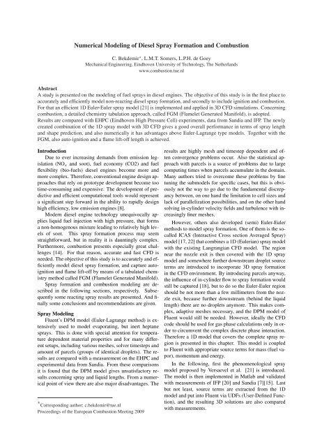
Abstract<br />
A study is presented on the modeling <strong>of</strong> fuel sprays in diesel engines. The objective <strong>of</strong> this study is in the first place to<br />
accurately <strong>and</strong> efficiently model non-reacting diesel spray formation, <strong>and</strong> secondly to include ignition <strong>and</strong> combustion.<br />
For that an efficient 1D Euler-Euler spray model [21] is implemented <strong>and</strong> applied in 3D CFD simulations. Concerning<br />
combustion, a detailed chemistry tabulation approach, called FGM (Flamelet Generated Manifold), is adopted.<br />
Results are compared with EHPC (Eindhoven High Pressure Cell) experiments, data from S<strong>and</strong>ia <strong>and</strong> IFP. The newly<br />
created combination <strong>of</strong> the 1D spray model with 3D CFD gives a good overall performance in terms <strong>of</strong> spray length<br />
<strong>and</strong> shape prediction, <strong>and</strong> also numerically it has advantages above Euler-Lagrange type models. Together with the<br />
FGM, also auto-ignition <strong>and</strong> a flame lift-<strong>of</strong>f length is achieved.<br />
Introduction<br />
Due to ever increasing dem<strong>and</strong>s from emission legislation<br />
(NOx <strong>and</strong> soot), fuel economy (CO2) <strong>and</strong> fuel<br />
flexibility (bio-fuels) diesel engines become more <strong>and</strong><br />
more complex. Therefore, conventional engine design approaches<br />
that rely on prototype development become too<br />
time-consuming <strong>and</strong> expensive. The development <strong>of</strong> predictive<br />
<strong>and</strong> efficient computational tools would represent<br />
a significant step forward in the ability to rapidly design<br />
high efficiency, low emission engines [8].<br />
Modern diesel engine technology unequivocally applies<br />
liquid fuel injection with high pressure, that forms<br />
a non-homogenous mixture leading to relatively high levels<br />
<strong>of</strong> soot. This spray formation process may seem<br />
straightforward, but in reality it is dauntingly complex.<br />
Furthermore, combustion presents especially great challenges<br />
[14]. For that reason, accurate <strong>and</strong> fast CFD is<br />
needed. The objective <strong>of</strong> this study is to accurately <strong>and</strong> efficiently<br />
model diesel spray formation, <strong>and</strong> capture autoignition<br />
<strong>and</strong> flame lift-<strong>of</strong>f by means <strong>of</strong> a tabulated chemistry<br />
method called FGM (Flamelet Generated Manifold).<br />
<strong>Spray</strong> formation <strong>and</strong> combustion modeling are described<br />
in the following sections, respectively. Subsequently<br />
some reacting spray results are presented. And finally<br />
some conclusions <strong>and</strong> recommendations are given.<br />
<strong>Spray</strong> <strong>Modeling</strong><br />
Fluent’s DPM model (Euler-Lagrange method) is extensively<br />
used to model evaporating, but inert heptane<br />
sprays. This is done with special attention for temperature<br />
dependent material properties <strong>and</strong> for many different<br />
setups, including various meshes, solver timesteps <strong>and</strong><br />
amount <strong>of</strong> parcels (groups <strong>of</strong> identical droplets). The results<br />
are compared with a measurement on the EHPC <strong>and</strong><br />
experimental data from S<strong>and</strong>ia. From these comparisons<br />
it is found that the DPM model gives unsatisfactory results<br />
concerning spray <strong>and</strong> liquid lengths. From a numerical<br />
point <strong>of</strong> view there are also major disadvantages. The<br />
∗ Corresponding author: c.bekdemir@tue.nl<br />
Proceedings <strong>of</strong> the European <strong>Combustion</strong> Meeting 2009<br />
results are highly mesh <strong>and</strong> timestep dependent <strong>and</strong> <strong>of</strong>ten<br />
convergence problems occur. Also the statistical approach<br />
with parcels is a source <strong>of</strong> problems due to large<br />
computing times when parcels accumulate in the domain.<br />
Many authors tried to overcome these problems by fine<br />
tuning the submodels for specific cases, but this is obviously<br />
not the way to go due to the fundamental discrepancy<br />
between, on one h<strong>and</strong> the limitation to cell sizes <strong>and</strong><br />
lack <strong>of</strong> parallelization possibilities, <strong>and</strong> on the other h<strong>and</strong><br />
solving in-cylinder velocity fields <strong>and</strong> turbulence with increasingly<br />
finer meshes.<br />
However, others also developed (semi) Euler-Euler<br />
methods to model spray formation. One <strong>of</strong> them is the socalled<br />
ICAS (Interactive Cross section Averaged <strong>Spray</strong>)<br />
model [17, 22] that combines a 1D (Eulerian) spray model<br />
with the existing Langrangian CFD model. The region<br />
near the nozzle exit is then covered with the 1D spray<br />
model <strong>and</strong> somewhere further downstream droplet source<br />
terms are introduced to incorporate 3D spray formation<br />
in the CFD environment. By introducing parcels anyway,<br />
the influence <strong>of</strong> in-cylinder flow to spray formation would<br />
still be captured [18], but to do so the Euler-Euler region<br />
should be not more than a few millimeters from the nozzle<br />
exit, because further downstream (behind the liquid<br />
length) there are no droplets anymore. This makes complex,<br />
adaptive meshes necessary, <strong>and</strong> the DPM model <strong>of</strong><br />
Fluent would still be needed. However, ideally the CFD<br />
code should be used for gas phase calculations only in order<br />
to circumvent the complex discrete phase interaction.<br />
Therefore a 1D model that covers the complete spray region<br />
is presented in this chapter. This model is coupled<br />
to Fluent with appropriate source terms for mass (fuel vapor),<br />
momentum <strong>and</strong> energy.<br />
In the following, first the phenomenological spray<br />
model proposed by Versaevel et al. [21] is introduced.<br />
The model is then implemented in Matlab <strong>and</strong> validated<br />
with measurements <strong>of</strong> IFP [20] <strong>and</strong> S<strong>and</strong>ia [7][15]. Last<br />
but not least, source terms are extracted from the 1D<br />
model <strong>and</strong> put into Fluent via UDFs (User-Defined Function),<br />
<strong>and</strong> the resulting 3D solutions are also compared<br />
with measurements.
1D Euler-Euler <strong>Spray</strong> Model<br />
The 1D quasi steady spray model <strong>of</strong> Versaevel et al.<br />
[21] is an extension <strong>of</strong> the earlier efforts <strong>of</strong> Naber et al.<br />
[11] <strong>and</strong> Siebers [15]. Naber <strong>and</strong> Siebers developed a 1D<br />
model for non-vaporizing spray penetration first, <strong>and</strong> later<br />
Siebers added some thermodynamics to distinguish liquid<br />
penetration from vapor penetration. But Siebers’ contribution<br />
is based on the assumption that only at the steady<br />
liquid length position thermodynamic equilibrium exists.<br />
This approach implies that no temperature information is<br />
available, except at the liquid length position. Also the<br />
composition <strong>of</strong> the spray volume between the nozzle exit<br />
<strong>and</strong> liquid length is unknown. Versaevel et al. overcame<br />
this shortcoming by introducing a void fraction m that<br />
couples the mass, momentum <strong>and</strong> energy equations.<br />
The model is based on five basic assumptions from<br />
which the first four are the same as in the work <strong>of</strong> Naber<br />
et al. [11] <strong>and</strong> Siebers [15].<br />
⇒ no velocity slip between gas <strong>and</strong> liquid phases<br />
⇒ whole system at constant pressure<br />
⇒ uniform velocity, density <strong>and</strong> temperature pr<strong>of</strong>iles<br />
⇒ constant spray angle<br />
⇒ whole system at thermodynamic equilibrium<br />
The last assumption is necessary to gain information<br />
about the temperature <strong>and</strong> composition <strong>of</strong> the spray in<br />
the entire 1D domain. The mass, momentum <strong>and</strong> energy<br />
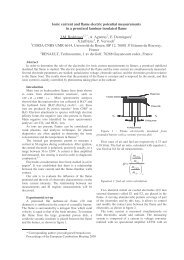
equations are derived by considering a control volume as<br />
defined in Figure 1. The spray is described in one direction<br />
due to the constant angle <strong>and</strong> the axisymmetry. The<br />
figure shows that from fuel injection ( ˙mfl,0) into the xdirection<br />
the spray diverges due to air entrainment ( ˙ma)<br />
into the spray volume. Air entrainment is controlled by<br />
the prescribed spray angle ( θ<br />
2 ). For this purpose an experimental<br />
dispersion relation is chosen. At the liquid length<br />
just enough hot air is entrained into the spray to evaporate<br />
all liquid fuel, so from that point on the fuel penetrates the<br />
surrounding gas as a vapor.<br />
The phenomenological spray model is implemented in<br />
Matlab. The st<strong>and</strong>ard non-linear solver <strong>of</strong> Matlab is used<br />
for this purpose. Material properties, except the liquid fuel<br />
.<br />
mfl,0<br />
.<br />
ma<br />
.<br />
ma<br />
control volume<br />
/2<br />
d eff<br />
gas <strong>and</strong> liquid gas only<br />
Figure 1: Definition <strong>of</strong> the control volume used in the derivation<br />
<strong>of</strong> the 1D model [21]<br />
df<br />
x<br />
2<br />
density, are temperature dependent, <strong>and</strong> are obtained from<br />
the thermophysical database <strong>of</strong> DIPPR [6]. The calculated<br />
spray length compares good with IFP measurements [20]<br />
as shown in Figure 2, indicated with the solid en dotted<br />
lines, respectively.<br />
SL [mm]<br />
50<br />
45<br />
40<br />
35<br />
30<br />
25<br />
20<br />
15<br />
case: IFP heptane<br />
10<br />
5<br />
3D model<br />
Fluent DPM<br />
1D model<br />
fit through IFP measurements<br />
0<br />
0 0.1 0.2 0.3 0.4 0.5<br />
Time [ms]<br />
0.6 0.7 0.8 0.9 1<br />
Figure 2: <strong>Spray</strong> length as function <strong>of</strong> time with the Euler-Euler<br />
3D model, compared to Fluent DPM, Euler-Euler 1D model <strong>and</strong><br />
IFP measurement<br />
3D <strong>Spray</strong> Simulation<br />
The 1D phenomenological spray model discussed in<br />
the previous section is, in contrary to the earlier model <strong>of</strong><br />
Naber <strong>and</strong> Siebers, suitable to apply in combination with a<br />
3D CFD code. To accomplish such an interaction, source<br />
terms are extracted from the 1D model <strong>and</strong> are assigned<br />
to the corresponding transport equations in Fluent (see [3]<br />
for the details). Subsequently the combined model is validated<br />
through spray length comparison with experimental<br />
data. IFP [20] <strong>and</strong> S<strong>and</strong>ia [15][7] measurements are used<br />
for validation purposes. These are all for single component<br />
fuels that are well documented, so thermophysical<br />
data needed for the numerical model is found in literature.<br />
The implemented 3D model (circles) predicts the<br />
spray length better than Fluent’s DPM model (stars), as is<br />
shown in Figure 2. The correctness <strong>of</strong> the 3D model prediction<br />
is best visualized with the contours <strong>of</strong> fuel mass<br />
fraction at the spray cross-section shown in Figure 3. The<br />
upper spray is a DPM simulation result <strong>and</strong> the other one<br />
is gained with the 3D model, both at 1 ms. Apart from the<br />
obvious spray length difference, the shape/width <strong>of</strong> the<br />
sprays are also dissimilar. DPM gives too wide sprays,<br />
since relatively large cells have to be used to meet the requirements<br />
<strong>of</strong> the Lagrangian approach. In the 3D Euler-<br />
Euler case one can refine the grid until the spray is resolved<br />
sufficiently, without having discrete phase related<br />
problems.<br />
Summarizing, the better overall performance (spray<br />
length <strong>and</strong> shape) <strong>and</strong> the proper mesh resolution behavior<br />
(higher resolution gives better solutions) <strong>of</strong> the 3D<br />
Euler-Euler model, together with the ability to parallelize<br />
is a major advantage compared with Fluent’s DPM model.<br />
Since the DPM model uses only one CPU to do all discrete
Figure 3: Case: IFP heptane. Contours <strong>of</strong> fuel mass fraction<br />
gained with Fluent’s DPM model <strong>and</strong> the implemented 3D spray<br />
model. Note the minimum/maximum values between the brackets<br />
at the right h<strong>and</strong> side, the colorbar is scaled for each separately<br />
phase calculations no matter how many CPUs are available.<br />
The consequence is large computation times despite<br />
the relatively small amount <strong>of</strong> cells.<br />
Possible improvements to the 1D/3D spray model for<br />
the future may be the following:<br />
⇒ Make 3D spray model pressure dependent in order to<br />
simulate spray formation in a variabele volume combustion<br />
chamber.<br />
⇒ Sound spray angle prediction. Not really an improvement<br />
to the model itself, but spray angle prediction<br />
certainly has a large effect on the final results. Therefore<br />
the quest for proper <strong>and</strong> generic angle prediction<br />
methods/relations should be promoted.<br />
<strong>Combustion</strong> <strong>Modeling</strong><br />
In the preceding chapters a 3D Euler-Euler spray<br />
model is implemented <strong>and</strong> validated for evaporating inert<br />
fuel sprays. This model is mesh <strong>and</strong> solver timestep<br />
independent, <strong>and</strong> is suitable for parallel simulations. So,<br />
regarding the status <strong>of</strong> modeling the mixing process, additional<br />
modeling features, which may require fine spatial<br />
<strong>and</strong> time resolutions, can be included. In this chapter an<br />
attempt is made to add combustion, more specific, the emphasis<br />
is on the application <strong>of</strong> FGMs (Flamelet Generated<br />
Manifolds) in modeling <strong>of</strong> the turbulent combustion <strong>of</strong> a<br />
transient igniting spray.<br />
In the following, first the principle <strong>of</strong> flamelets <strong>and</strong> its<br />
use for modeling combustion with tabulated chemistry is<br />
shortly mentioned. Then, the procedure <strong>of</strong> a FGM generation<br />
is shown. Subsequently, its implementation into<br />
Fluent is described.<br />
FGM Approach<br />
Detailed models can be very accurate, but unfortunately<br />
also computationally very expensive. To overcome<br />
3<br />
the impractical computing times, while solving the combustion<br />
process still with high detail (depends on used reaction<br />
scheme), an approach with tabulated chemistry is<br />
applied. This so-called FGM approach is developed by<br />
van Oijen [19] for laminar premixed flames, <strong>and</strong> makes<br />
use <strong>of</strong> 1D laminar flamelet data to tabulate composition,<br />
density, temperature etc. as function <strong>of</strong> local control<br />
variables. However, the flamelet concept views a turbulent<br />
flame as an ensemble <strong>of</strong> thin, laminar, locally 1D<br />
flames, called flamelets, embedded within the turbulent<br />
flow field. Furthermore, the concept is based on the assumption<br />
that the smallest turbulent time <strong>and</strong> length scales<br />
are much larger than the chemical ones, <strong>and</strong> there exists a<br />
locally undisturbed sheet where chemical reactions occur<br />
[16]. So, later Ramaekers [13] extended the application to<br />
turbulent partially-premixed combustion by choosing one<br />
control variable describing non-premixed (mixture fraction<br />
Z) <strong>and</strong> one describing premixed (reaction progress<br />
variable P V ) combustion, <strong>and</strong> by PDF (Probability Density<br />
Function) integration to account for turbulence.<br />
In this study non-premixed flamelets for a counterflow<br />
setup are solved with CHEM1D [1], which is a specialized<br />
one-dimensional laminar flame code developed at the<br />
Eindhoven University <strong>of</strong> Technology. A heptane flamelet<br />
database at constant pressure is calculated, making use <strong>of</strong><br />
a reduced n-heptane mechanism [12].<br />
In non-premixed combustion it is common practice to<br />
introduce the mixture fraction Z, here the definition <strong>of</strong><br />
Bilger [4] is adopted:<br />
Z =<br />
2 YC−YC,2<br />
MC<br />
2 YC,1−YC,2<br />
MC<br />
1 +<br />
YH −YH,2 (YO−YO,2)<br />
2 − MH<br />
MO<br />
+ 1 YH,1−YH,2<br />
2 − MH<br />
YO,1−YO,2<br />
MO<br />
, (1)<br />
where Y st<strong>and</strong>s for mass fraction, M is the molar mass<br />
<strong>and</strong> the subscripts C, H <strong>and</strong> O indicate the quantities<br />
for the elements carbon, hydrogen <strong>and</strong> oxygen, respectively.<br />
The subscripts 1 <strong>and</strong> 2 refer to the constant mass<br />
fraction in the original fuel <strong>and</strong> oxidizer streams, respectively.<br />
In the fuel stream the mixture fraction is equal to<br />
unity <strong>and</strong> monotonically decreases to zero at the oxidizer<br />
stream. An additional control variable, called the reaction<br />
progress variable P V , is introduced to parameterize the<br />
progress <strong>of</strong> the irreversible combustion process. In this<br />
study a combination <strong>of</strong> CO2, CO <strong>and</strong> CH2O mass fractions<br />
is chosen as a reaction progress variable:<br />
P V = YCO2<br />
MCO2<br />
+ YCO<br />
+<br />
MCO<br />
YCH2O<br />
. (2)<br />
MCH2O<br />
The succes <strong>of</strong> this concept is related to the fact that<br />
all occurring compositions tend to have a common,<br />
low-dimensional, attractor in composition space, a socalled<br />
intrinsic low-dimensional manifold (ILDM) [9].<br />
Hence, the complex chemistry is reduced <strong>and</strong> completely<br />
described by the mixture fraction Z <strong>and</strong> the reaction<br />
progress variable P V .<br />
FGM Construction <strong>and</strong> Implementation<br />
FGMs can be generated in many ways. For stationary<br />
flames, there is a classical way with steady flamelets only,
PV [−]<br />
Flamelet database generation<br />
igniting flamelet<br />
extinguishing flamelet<br />
igniting PSRs<br />
0 0.1 0.2 0.3 0.4 0.5<br />
Z [−]<br />
0.6 0.7 0.8 0.9 1<br />
Lowest strainrate<br />
Steady solutions region<br />
Highest non−quenching strainrate<br />
Timedependently extinguishing or igniting flamelet<br />
Perfectly Stirred Reactors (PSRs) before ignition<br />
Figure 4: Ways to generate a ’full’ flamelet database<br />
where a sequence <strong>of</strong> steady flames with strainrates varying<br />
from a low value to the quenching value is computed.<br />
An illustrative example is shown in Figure 4, see the gray<br />
area between the solution for the lowest strainrate <strong>and</strong> the<br />
solution at which the strainrate reached its maximum before<br />
extinction.<br />
But a spray event is unsteady <strong>and</strong> initially nonreacting,<br />
so to cover the ignition process the table should<br />
also contain information in the area beneath the quenching<br />
strainrate solution. Several ways exist to fill this gap<br />
in the Z-P V plane. One way is to solve a timedependent<br />
flamelet with a higher strainrate than the highest possible<br />
non-quenching strainrate, in this way forcing the flame to<br />
extinguish <strong>and</strong> in the mean time sampling data to fill the<br />
gap. Another approach, that is more appropriate for this<br />
study, is solving timedependent flamelets from a mixed,<br />
but non-reacting initial state. The ignition behavior is followed<br />
in time until a steady flame is reached. The third<br />
possibility is to reproduce ignition <strong>of</strong> mixtures covering<br />
the entire Z-space with PSR (Perfectly Stirred Reactor)<br />
auto-ignition calculations [10]. All three methods to fill<br />
the Z-P V gap are depicted schematically in Figure 4.<br />
The way(s) a FGM is constructed in this study is depicted<br />
schematically in Figure 5.<br />
Due to the unsteady nature <strong>of</strong> a diesel injection event,<br />
ignition modeling is at least as important as combustion<br />
modeling. Following the FGM approach, besides combustion,<br />
ignition should be covered inherently. But not<br />
surprisingly this depends on the way the FGM is generated.<br />
The extinguishing flamelet approach is applied <strong>and</strong><br />
does not lead to ignition <strong>of</strong> the spray. Instead, only local<br />
temperatures slightly above the initial ambient temperature<br />
are found, <strong>and</strong> the source <strong>of</strong> the reaction progress<br />
variable is not big enough to end in total ignition within<br />
a few milliseconds. However, a FGM constructed with<br />
4<br />
an igniting flamelet database does result is auto-ignition<br />
<strong>of</strong> the whole spray in short time. Therefore, in this paper<br />
only the results <strong>of</strong> the igniting flamelet approach are<br />
presented.<br />
The turbulence-chemistry interaction is accounted for<br />
by integrating the quantities ϕ in the 2D table with a β-<br />
PDF function as follows:<br />
˜ϕ =<br />
1 1<br />
0<br />
0<br />
ϕ(Z, P V ) ˜ P (Z) ˜ P (P V ) dZdP V. (3)<br />
Note that this explicit formulation assumes that Z <strong>and</strong><br />
P V are statistically independent. The overtilde st<strong>and</strong>s for<br />
Favre (mass) averaged. Both control variables are from<br />
then on described with a mean value ( ˜ Z, P V ) <strong>and</strong> a variance<br />
(Z” 2 , P V ” 2 ), so a quantity is defined by the probability<br />
<strong>of</strong> occurrence for several states instead <strong>of</strong> one fixed<br />
state. The chemistry is in this way extended to a 4D lookup<br />
table with the means <strong>and</strong> variances <strong>of</strong> the two control<br />
variables as the parameters (look-up indices).<br />
The 4D FGM combustion model is implemented in<br />
Fluent, in order to do turbulent spray combustion simulations<br />
in 3D space. The four scalars ( ˜ Z, P V , Z” 2 , P V ” 2 )<br />
are solved with user-defined scalar transport equations, in<br />
addition to the st<strong>and</strong>ard continuity, momentum <strong>and</strong> turbulence<br />
equations. All species concentrations <strong>and</strong> corre-<br />
quenching flame<br />
Z-PV domain filled with<br />
stationary loop over strainrates ,<br />
<strong>and</strong> with timedependent<br />
quenching flame<br />
TRF mechanism<br />
48 species<br />
248 reactions<br />
CHEM1D<br />
solves:<br />
flamelet equations<br />
(constant pressure )<br />
2D FGM<br />
Z, PV – table<br />
(laminar)<br />
interpolated laminar flamelet data ρ,<br />
sPV, Yi <strong>and</strong> T as function <strong>of</strong><br />
Z <strong>and</strong> PV<br />
4D FGM<br />
"2 "2<br />
Z, Z , PV ,PV – table<br />
(turbulence included )<br />
2D data integrated with PDF<br />
functions. ρ, sPVm, <br />
"2<br />
sPV ,sPV sPVv, Yi <strong>and</strong> T<br />
as function <strong>of</strong> mmmmmmmm "2<br />
, , "2<br />
Z Z PV ,PV<br />
Figure 5: FGM construction scheme<br />
igniting flame<br />
Z-PV domain filled with , from<br />
initial pure mixing solution ,<br />
igniting flame , using the<br />
timedependent solver
sponding temperatures are in principle known from the<br />
flamelet database for any mixture fraction <strong>and</strong> progress<br />
variable combination.<br />
Results <strong>and</strong> Discussion<br />
The evolution from the early stage <strong>of</strong> ignition to further<br />
combustion <strong>of</strong> the spray, injected from the left, is<br />
shown at six moments in time in Figure 6. The upper half<br />
<strong>of</strong> the plots represent the values <strong>of</strong> the progress variable<br />
<strong>and</strong> the lower parts are contours <strong>of</strong> temperature. Several<br />
interesting observations are done from this figure. First, at<br />
the outer edge <strong>of</strong> the spray activity begins, here shown by<br />
means <strong>of</strong> an increased (<strong>and</strong> still increasing) progress variable<br />
<strong>and</strong> a corresponding increase in temperature; from<br />
an initial 800 K ambient to around 1000 K locally. This<br />
activity is particularly present close to the place the flame<br />
lift-<strong>of</strong>f will settle. Further in time the outer contour <strong>of</strong> the<br />
igniting spray is becoming clearer due to high values <strong>of</strong><br />
P V <strong>and</strong> T . Finally, the full outer edge will be reacting<br />
<strong>and</strong> the combustion region exp<strong>and</strong>s to the inner volume<br />
<strong>and</strong> the maximum temperature continues to rise.<br />
Also a much simpler combustion model is used that<br />
is available in Fluent, called eddy-dissipation model [2].<br />
This model is, like the flamelet approach, a mixinglimited<br />
combustion model, with the differences that only<br />
the global reaction from fuel <strong>and</strong> O2 to CO2 <strong>and</strong> H2O is<br />
considered <strong>and</strong> immediate reaction is assumed. So, it is<br />
not expected that this simple model can be as accurate as<br />
the much more detailed FGM method, but it gives nice<br />
material to compare regarding for example temperature<br />
pr<strong>of</strong>iles. Such a comparative picture is given in Figure 7,<br />
taken at 1 ms. In contrast to the eddy-dissipation model,<br />
apart from the inherent auto-ignition, also a flame lift-<strong>of</strong>f<br />
settles automatically using tabulated chemistry.<br />
The diffusion flame at the spray edge stays the hottest<br />
region, as can be expected on the basis <strong>of</strong> the used nonpremixed<br />
flamelet database. But according to the conceptual<br />
diesel combustion model <strong>of</strong> Dec [5] it is stated that<br />
in DI diesel injection, regions with premixed <strong>and</strong> nonpremixed<br />
combustion can be distinguished. The next step<br />
Tmax = 807 K Tmax = 853 K<br />
Figure 6: Case: IFP heptane. Temporal sequence <strong>of</strong> progress<br />
variable <strong>and</strong> temperature contours showing the auto-ignition<br />
process resulting in total combustion<br />
5<br />
Figure 7: Case: IFP heptane. Contours <strong>of</strong> temperature gained<br />
with the eddy-dissipation model <strong>and</strong> the implemented FGM<br />
model. Note the minimum/maximum values between the brackets<br />
at the right h<strong>and</strong> side, the colorbar is scaled for each separately<br />
may be the creation <strong>of</strong> a partially-premixed database in<br />
order to capture the presence <strong>of</strong> both regimes at the same<br />
time.<br />
Unfortunately, there are no experimental ignition delay<br />
<strong>and</strong> lift-<strong>of</strong>f length data published for this case in the<br />
paper <strong>of</strong> Verhoeven et al. [20]. However, the numerically<br />
found delay time <strong>and</strong> lift-<strong>of</strong>f length are in the order<br />
<strong>of</strong> magnitude <strong>of</strong> comparable fuel sprays. Also two important<br />
observations that are reported by Verhoeven et al.<br />
are the auto-ignition position <strong>and</strong> the subsequent burning<br />
behavior. They state that the first visible emission corresponds<br />
roughly to the flame lift-<strong>of</strong>f distance during quasisteady<br />
state combustion phase observed later. And that<br />
this auto-ignited kernel progresses along the spray until<br />
it reaches the tip, after which no other development occurs,<br />
except for further penetration. The above presented<br />
numerical results <strong>of</strong> the Euler-Euler spray model together<br />
with the FGM combustion model is completely coherent<br />
with these experimental observations.<br />
Conclusions<br />
A 1D Euler-Euler spray model is implemented into 3D<br />
CFD (Fluent). This 3D spray model is validated with inert<br />
fuel spray penetration measurements <strong>and</strong> is able to predict<br />
spray lengths <strong>and</strong> shapes quantitatively well. It also<br />
<strong>of</strong>fers the advantage <strong>of</strong> a proper mesh resolution behavior<br />
(higher resolution gives better solutions), <strong>and</strong> is suitable<br />
for parallel computing.<br />
<strong>Combustion</strong> <strong>of</strong> the fuel spray is modeled with a tabulated<br />
chemistry approach (FGM). The manifold is created<br />
with igniting diffusion flame solutions. Important characteristics<br />
like auto-ignition <strong>and</strong> flame lift-<strong>of</strong>f are captured<br />
without explicitly modeling them, showing the generic nature<br />
<strong>and</strong> therefore the potential <strong>of</strong> the applied method.<br />
A first study with heptane as a surrogate for diesel
fuel shows promising results concerning spray formation,<br />
<strong>and</strong> subsequently auto-ignition <strong>and</strong> the settling <strong>of</strong> a lift-<strong>of</strong>f<br />
length.<br />
Outlook - Future Research<br />
In the future, direct validation with ignition delay<br />
times <strong>and</strong> flame lift-<strong>of</strong>f lengths will be done. And at the<br />
same time the influence <strong>of</strong> the preprocessing phase on the<br />
combustion behavior will be investigated. One can think<br />
about the choice <strong>of</strong> a progress variable <strong>and</strong> the applied<br />
FGM generation method.<br />
References<br />
[1] CHEM1D, A one-dimensional laminar flame<br />
code, Eindhoven University <strong>of</strong> Technology,<br />
http://www.combustion.tue.nl/chem1d.<br />
[2] Fluent 6.3 User’s Guide, September 2006.<br />
[3] C. Bekdemir. <strong>Numerical</strong> modeling <strong>of</strong> diesel spray<br />
formation <strong>and</strong> combustion. Master’s thesis, Eindhoven<br />
University <strong>of</strong> Technology, <strong>Combustion</strong> Technology,<br />
2008.<br />
[4] R.W. Bilger, S.H. Starner, <strong>and</strong> R.J. Kee. On reduced<br />
mechanisms for methane-air combustion in nonpremixed<br />
flames. <strong>Combustion</strong> <strong>and</strong> Flame, 80:135–<br />
149, 1990.<br />
[5] John E. Dec. A conceptual model <strong>of</strong> di diesel combustion<br />
based on laser-sheet imaging. SAE paper,<br />
(SAE 970873), February 1997.<br />
[6] DIPPR Design Institute for Physical Properties.<br />
http://dippr.byu.edu/.<br />
[7] ECN Engine <strong>Combustion</strong> Network.<br />
http://public.ca.s<strong>and</strong>ia.gov/ecn/index.php.<br />
[8] J.T. Farrell, N.P. Cernansky, F.L. Dryer, D.G. Friend,<br />
C.A. Hergart, C.K. Law, R.M. McDavid, C.J.<br />
Mueller, A.K. Patel, <strong>and</strong> H. Pitsch. Development<br />
<strong>of</strong> an experimental database <strong>and</strong> kinetic models for<br />
surrogate diesel fuels. SAE paper, (SAE 2007-01-<br />
0201), 2007.<br />
[9] U. Maas <strong>and</strong> S.B. Pope. Simplifying chemical kinetics:<br />
Intrinsic low-dimensional manifolds in composition<br />
space. <strong>Combustion</strong> <strong>and</strong> Flame, 88(1992):239–<br />
264, 1992.<br />
[10] Jean-Baptiste Michel, Olivier Colin, <strong>and</strong> Denis Veynante.<br />
<strong>Modeling</strong> ignition <strong>and</strong> chemical structure <strong>of</strong><br />
partially premixed turbulent flames using tabulated<br />
chemistry. <strong>Combustion</strong> <strong>and</strong> Flame, 152(2008):80–<br />
99, September 2007.<br />
[11] Jeffrey D. Naber <strong>and</strong> Dennis L. Siebers. Effects <strong>of</strong><br />
gas density <strong>and</strong> vaporization on penetration <strong>and</strong> dispersion<br />
<strong>of</strong> diesel sprays. SAE paper, (SAE 960034),<br />
February 1996.<br />
[12] N. Peters, G. Paczko, R. Seiser, <strong>and</strong> K. Seshadri.<br />
Temperature cross-over <strong>and</strong> non-thermal runaway at<br />
two-stage ignition <strong>of</strong> n-heptane. <strong>Combustion</strong> <strong>and</strong><br />
Flame, 128:38–59, 2002.<br />
[13] W.J.S. Ramaekers. The application <strong>of</strong> flamelet generated<br />
manifolds in modelling <strong>of</strong> turbulent partiallypremixed<br />
flames. Master’s thesis, Eindhoven Uni-<br />
6<br />
versity <strong>of</strong> Technology, <strong>Combustion</strong> Technology,<br />
2005.<br />
[14] R.D. Reitz <strong>and</strong> C.J. Rutl<strong>and</strong>. Development <strong>and</strong> testing<br />
<strong>of</strong> diesel engine cfd models. Prog. Energy Combust.<br />
Sci., 21:173–196, 1995.<br />
[15] Dennis L. Siebers. Scaling liquid-phase fuel penetration<br />
in diesel sprays based on mixing-limited vaporization.<br />
SAE paper, (SAE 1999-01-0528), March<br />
1999.<br />
[16] Satbir Singh, Rolf D. Reitz, <strong>and</strong> Mark P.B. Musculus.<br />
Comparison <strong>of</strong> the characteristic time (ctc), representative<br />
interactive flamelet (rif), <strong>and</strong> direct integration<br />
with detailed chemistry combustion models<br />
against optical diagnostic data for multi-mode<br />
di diesel engine. SAE paper, (SAE 2006-01-0055),<br />
April 2006.<br />
[17] R. Steiner, C. Bauer, C. Kruger, F. Otto, <strong>and</strong><br />
U. Maas. 3d-simulation <strong>of</strong> di-diesel combustion applying<br />
a progress variable approach accounting for<br />
complex chemistry. SAE paper, (SAE 2004-01-<br />
0106), March 2004.<br />
[18] G. Stiesch. <strong>Modeling</strong> engine spray <strong>and</strong> combustion<br />
processes. Springer, Berlin, 2003.<br />
[19] J.A. van Oijen. Flamelet-Generated Manifolds: Development<br />
<strong>and</strong> Application to Premixed Laminar<br />
Flames. PhD thesis, Eindhoven University <strong>of</strong> Technology,<br />
<strong>Combustion</strong> Technology, 2002.<br />
[20] Dean Verhoeven, Jean-Luc Vanhemelryck, <strong>and</strong><br />
Thierry Baritaud. Macroscopic <strong>and</strong> ignition<br />
characteristics <strong>of</strong> high-pressure sprays <strong>of</strong> singlecomponent<br />
fuels. SAE paper, (SAE 981069), February<br />
1998.<br />
[21] Philippe Versaevel, Paul Motte, <strong>and</strong> Karl Wieser. A<br />
new 3d model for vaporizing diesel sprays based<br />
on mixing-limited vaporization. SAE paper, (SAE<br />
2000-01-0949), March 2000.<br />
[22] Y.P. Wan <strong>and</strong> N. Peters. Application <strong>of</strong> the crosssectional<br />
average method to calculations <strong>of</strong> the<br />
dense spray region in a diesel engine. SAE paper,<br />
(SAE 972866), 1997.