

Calumet Travelite Manual - Stephen Grote
Calumet Travelite Manual - Stephen Grote
Calumet Travelite Manual - Stephen Grote

You also want an ePaper? Increase the reach of your titles
YUMPU automatically turns print PDFs into web optimized ePapers that Google loves.
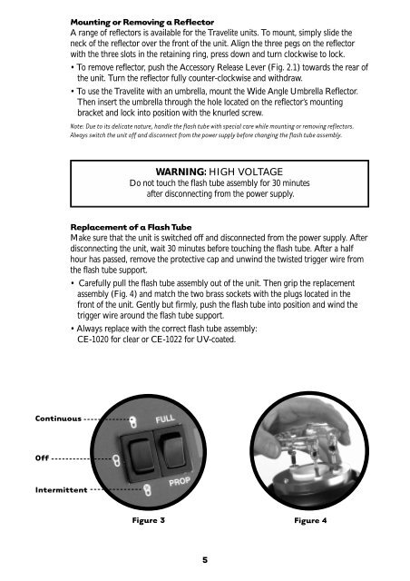
Continuous<br />
Off<br />
Intermittent<br />
Mounting or Removing a Reflector<br />
A range of reflectors is available for the <strong>Travelite</strong> units. To mount, simply slide the<br />
neck of the reflector over the front of the unit. Align the three pegs on the reflector<br />
with the three slots in the retaining ring, press down and turn clockwise to lock.<br />
• To remove reflector, push the Accessory Release Lever (Fig. 2.1) towards the rear of<br />
the unit. Turn the reflector fully counter-clockwise and withdraw.<br />
• To use the <strong>Travelite</strong> with an umbrella, mount the Wide Angle Umbrella Reflector.<br />
Then insert the umbrella through the hole located on the reflector’s mounting<br />
bracket and lock into position with the knurled screw.<br />
Note: Due to its delicate nature, handle the flash tube with special care while mounting or removing reflectors.<br />
Always switch the unit off and disconnect from the power supply before changing the flash tube assembly.<br />
WARNING: HIGH VOLTAGE<br />
Do not touch the flash tube assembly for 30 minutes<br />
after disconnecting from the power supply.<br />
Replacement of a Flash Tube<br />
Make sure that the unit is switched off and disconnected from the power supply. After<br />
disconnecting the unit, wait 30 minutes before touching the flash tube. After a half<br />
hour has passed, remove the protective cap and unwind the twisted trigger wire from<br />
the flash tube support.<br />
• Carefully pull the flash tube assembly out of the unit. Then grip the replacement<br />
assembly (Fig. 4) and match the two brass sockets with the plugs located in the<br />
front of the unit. Gently but firmly, push the flash tube into position and wind the<br />
trigger wire around the flash tube support.<br />
• Always replace with the correct flash tube assembly:<br />
CE-1020 for clear or CE-1022 for UV-coated.<br />
Figure 3<br />
5<br />
Figure 4