System x3630 M3 Type 7377: Installation and User?s Guide
System x3630 M3 Type 7377: Installation and User?s Guide
System x3630 M3 Type 7377: Installation and User?s Guide

You also want an ePaper? Increase the reach of your titles
YUMPU automatically turns print PDFs into web optimized ePapers that Google loves.
<strong>System</strong> <strong>x3630</strong> <strong>M3</strong> <strong>Type</strong> <strong>7377</strong><br />
<strong>Installation</strong> <strong>and</strong> <strong>User</strong>’s <strong>Guide</strong>
<strong>System</strong> <strong>x3630</strong> <strong>M3</strong> <strong>Type</strong> <strong>7377</strong><br />
<strong>Installation</strong> <strong>and</strong> <strong>User</strong>’s <strong>Guide</strong>
Note: Before using this information <strong>and</strong> the product it supports, read the information in Appendix B, “Notices,” on page 107, the IBM<br />
Safety Information <strong>and</strong> Environmental Notices <strong>and</strong> <strong>User</strong> <strong>Guide</strong> documents on the IBM Documentation CD, <strong>and</strong> the Warranty<br />
Information document.<br />
The most recent version of this document is available at http://www.ibm.com/systems/support/.<br />
Fourth Edition (February 2012)<br />
© Copyright IBM Corporation 2012.<br />
US Government <strong>User</strong>s Restricted Rights – Use, duplication or disclosure restricted by GSA ADP Schedule Contract<br />
with IBM Corp.
Contents<br />
Safety . . . . . . . . . . . . . . . . . . . . . . . . . . . . vii<br />
Chapter 1. The <strong>System</strong> <strong>x3630</strong> <strong>M3</strong> <strong>Type</strong> <strong>7377</strong> server . . . . . . . . . . . 1<br />
The IBM Documentation CD . . . . . . . . . . . . . . . . . . . . 3<br />
Hardware <strong>and</strong> software requirements . . . . . . . . . . . . . . . . 3<br />
Using the Documentation Browser . . . . . . . . . . . . . . . . . 3<br />
Related documentation . . . . . . . . . . . . . . . . . . . . . . 4<br />
Notices <strong>and</strong> statements in this document . . . . . . . . . . . . . . . . 6<br />
Features <strong>and</strong> specifications . . . . . . . . . . . . . . . . . . . . . 6<br />
What your server offers . . . . . . . . . . . . . . . . . . . . . . 8<br />
Reliability, availability, <strong>and</strong> serviceability features . . . . . . . . . . . . 11<br />
IBM <strong>System</strong>s Director . . . . . . . . . . . . . . . . . . . . . . 12<br />
The UpdateXpress <strong>System</strong> Pack Installer . . . . . . . . . . . . . . . 13<br />
Server controls, LEDs, <strong>and</strong> power . . . . . . . . . . . . . . . . . . 13<br />
Front view . . . . . . . . . . . . . . . . . . . . . . . . . 13<br />
Rear view . . . . . . . . . . . . . . . . . . . . . . . . . . 14<br />
Server power features . . . . . . . . . . . . . . . . . . . . . 17<br />
Chapter 2. Installing optional devices. . . . . . . . . . . . . . . . 19<br />
Instructions for IBM Business Partners . . . . . . . . . . . . . . . . 19<br />
Server components . . . . . . . . . . . . . . . . . . . . . . . 20<br />
<strong>System</strong>-board internal connectors . . . . . . . . . . . . . . . . . 21<br />
<strong>System</strong>-board DIMM connectors . . . . . . . . . . . . . . . . . 22<br />
<strong>System</strong>-board external connectors. . . . . . . . . . . . . . . . . 23<br />
<strong>System</strong>-board jumpers . . . . . . . . . . . . . . . . . . . . . 24<br />
<strong>System</strong>-board LEDs . . . . . . . . . . . . . . . . . . . . . . 26<br />
Fan board connectors . . . . . . . . . . . . . . . . . . . . . 28<br />
PCI riser-card adapter connectors . . . . . . . . . . . . . . . . . 28<br />
<strong>Installation</strong> guidelines . . . . . . . . . . . . . . . . . . . . . . 29<br />
<strong>System</strong> reliability guidelines . . . . . . . . . . . . . . . . . . . 30<br />
Working inside the server with the power on . . . . . . . . . . . . . 30<br />
H<strong>and</strong>ling static-sensitive devices . . . . . . . . . . . . . . . . . 31<br />
Internal cable routing <strong>and</strong> connectors . . . . . . . . . . . . . . . . 32<br />
Hot-swap hard disk drive backplane cable connections . . . . . . . . . 32<br />
Removing the cover . . . . . . . . . . . . . . . . . . . . . . . 33<br />
Rotating the optional hot-swap rear hard disk drive cage up . . . . . . . . 34<br />
Removing the air baffle . . . . . . . . . . . . . . . . . . . . . . 35<br />
Removing the PCI riser-card assembly . . . . . . . . . . . . . . . . 36<br />
Installing an adapter . . . . . . . . . . . . . . . . . . . . . . . 37<br />
Installing a ServeRAID adapter . . . . . . . . . . . . . . . . . . . 38<br />
Installing a ServeRAID adapter battery on the remote battery tray . . . . . . 40<br />
Installing an optional ServeRAID adapter advanced feature key . . . . . . . 44<br />
Installing an IBM Virtual Media Key . . . . . . . . . . . . . . . . . 45<br />
Installing a hot-swap hard disk drive . . . . . . . . . . . . . . . . . 47<br />
Removing a hot-swap hard disk drive . . . . . . . . . . . . . . . . 48<br />
Installing an optional rear hot-swap SAS/SATA rear 3.5-inch hard disk drive<br />
cage . . . . . . . . . . . . . . . . . . . . . . . . . . . . 48<br />
Installing an optional rear hot-swap SAS/SATA rear 2.5-inch hard disk drive<br />
cage . . . . . . . . . . . . . . . . . . . . . . . . . . . . 55<br />
Installing the hot-swap backplane on the optional rear hard disk drive cage 61<br />
Installing a memory module . . . . . . . . . . . . . . . . . . . . 62<br />
DIMM installation sequence . . . . . . . . . . . . . . . . . . . 64<br />
Memory mirroring . . . . . . . . . . . . . . . . . . . . . . . 65<br />
© Copyright IBM Corp. 2012 iii
Online-spare memory . . . . . . . . . . . . . . . . . . . . . 66<br />
Installing a DIMM . . . . . . . . . . . . . . . . . . . . . . . 67<br />
Installing a second microprocessor . . . . . . . . . . . . . . . . . 69<br />
Thermal grease. . . . . . . . . . . . . . . . . . . . . . . . 74<br />
Installing a hot-swap power supply . . . . . . . . . . . . . . . . . 75<br />
Installing a USB hypervisor memory key . . . . . . . . . . . . . . . 77<br />
Completing the installation. . . . . . . . . . . . . . . . . . . . . 78<br />
Installing the PCI riser-card assembly . . . . . . . . . . . . . . . 78<br />
Installing the air baffle . . . . . . . . . . . . . . . . . . . . . 79<br />
Rotating the optional hot-swap rear hard disk drive cage down . . . . . . 79<br />
Installing the server cover . . . . . . . . . . . . . . . . . . . . 80<br />
Connecting the external cables . . . . . . . . . . . . . . . . . . 82<br />
Updating the server configuration . . . . . . . . . . . . . . . . . 83<br />
Chapter 3. Configuring the server . . . . . . . . . . . . . . . . . 85<br />
Using the Setup utility . . . . . . . . . . . . . . . . . . . . . . 86<br />
Starting the Setup utility . . . . . . . . . . . . . . . . . . . . 86<br />
Setup utility menu choices. . . . . . . . . . . . . . . . . . . . 87<br />
Passwords . . . . . . . . . . . . . . . . . . . . . . . . . 90<br />
Using the Boot Selection Menu program . . . . . . . . . . . . . . . 91<br />
Starting the backup server firmware . . . . . . . . . . . . . . . . . 91<br />
Using the Server<strong>Guide</strong> Setup <strong>and</strong> <strong>Installation</strong> CD . . . . . . . . . . . . 92<br />
Server<strong>Guide</strong> features . . . . . . . . . . . . . . . . . . . . . 92<br />
Setup <strong>and</strong> configuration overview . . . . . . . . . . . . . . . . . 93<br />
Typical operating-system installation . . . . . . . . . . . . . . . . 93<br />
Installing your operating system without using Server<strong>Guide</strong> . . . . . . . 93<br />
Using the integrated management module . . . . . . . . . . . . . . . 94<br />
Using the USB memory key for VMware hypervisor . . . . . . . . . . . 95<br />
Using the remote presence capability <strong>and</strong> blue-screen capture . . . . . . . 96<br />
Enabling the remote presence feature . . . . . . . . . . . . . . . 96<br />
Obtaining the IP address for the Web interface access . . . . . . . . . 96<br />
Logging on to the Web interface . . . . . . . . . . . . . . . . . 97<br />
Configuring the Gigabit Ethernet controller . . . . . . . . . . . . . . . 97<br />
Enabling <strong>and</strong> configuring Serial over LAN (SOL) . . . . . . . . . . . . 98<br />
UEFI update <strong>and</strong> configuration . . . . . . . . . . . . . . . . . . 98<br />
Using the LSI Logic Configuration Utility program . . . . . . . . . . . . 99<br />
Starting the LSI Logic Configuration Utility program . . . . . . . . . . 100<br />
Formatting a hard disk drive . . . . . . . . . . . . . . . . . . 100<br />
Creating a mirrored pair of hard disk drives . . . . . . . . . . . . . 101<br />
Configuring a ServeRAID controller . . . . . . . . . . . . . . . . . 101<br />
IBM Advanced Settings Utility program. . . . . . . . . . . . . . . . 101<br />
Updating the firmware . . . . . . . . . . . . . . . . . . . . . . 102<br />
Updating IBM <strong>System</strong>s Director . . . . . . . . . . . . . . . . . . 103<br />
Appendix A. Getting help <strong>and</strong> technical assistance . . . . . . . . . . 105<br />
Before you call . . . . . . . . . . . . . . . . . . . . . . . . 105<br />
Using the documentation . . . . . . . . . . . . . . . . . . . . . 105<br />
Getting help <strong>and</strong> information from the World Wide Web . . . . . . . . . 105<br />
Software service <strong>and</strong> support . . . . . . . . . . . . . . . . . . . 106<br />
Hardware service <strong>and</strong> support . . . . . . . . . . . . . . . . . . . 106<br />
IBM Taiwan product service . . . . . . . . . . . . . . . . . . . . 106<br />
Appendix B. Notices . . . . . . . . . . . . . . . . . . . . . . 107<br />
Trademarks. . . . . . . . . . . . . . . . . . . . . . . . . . 107<br />
Important notes . . . . . . . . . . . . . . . . . . . . . . . . 108<br />
Particulate contamination. . . . . . . . . . . . . . . . . . . . . 109<br />
iv <strong>System</strong> <strong>x3630</strong> <strong>M3</strong> <strong>Type</strong> <strong>7377</strong>: <strong>Installation</strong> <strong>and</strong> <strong>User</strong>’s <strong>Guide</strong>
Documentation format . . . . . . . . . . . . . . . . . . . . . . 109<br />
Telecommunication regulatory statement . . . . . . . . . . . . . . . 110<br />
Electronic emission notices . . . . . . . . . . . . . . . . . . . . 110<br />
Federal Communications Commission (FCC) statement . . . . . . . . 110<br />
Industry Canada Class A emission compliance statement . . . . . . . . 110<br />
Avis de conformité à la réglementation d'Industrie Canada . . . . . . . 110<br />
Australia <strong>and</strong> New Zeal<strong>and</strong> Class A statement . . . . . . . . . . . . 110<br />
European Union EMC Directive conformance statement . . . . . . . . 111<br />
Germany Class A statement. . . . . . . . . . . . . . . . . . . 111<br />
Japan VCCI Class A statement . . . . . . . . . . . . . . . . . 112<br />
Japan Electronics <strong>and</strong> Information Technology Industries Association (JEITA)<br />
statement . . . . . . . . . . . . . . . . . . . . . . . . 112<br />
Korea Communications Commission (KCC) statement . . . . . . . . . 112<br />
Russia Electromagnetic Interference (EMI) Class A statement . . . . . . 113<br />
People's Republic of China Class A electronic emission statement . . . . 113<br />
Taiwan Class A compliance statement . . . . . . . . . . . . . . . 113<br />
Index . . . . . . . . . . . . . . . . . . . . . . . . . . . . 115<br />
Contents v
vi <strong>System</strong> <strong>x3630</strong> <strong>M3</strong> <strong>Type</strong> <strong>7377</strong>: <strong>Installation</strong> <strong>and</strong> <strong>User</strong>’s <strong>Guide</strong>
Safety<br />
Before installing this product, read the Safety Information.<br />
Antes de instalar este produto, leia as Informações de Segurança.<br />
Læs sikkerhedsforskrifterne, før du installerer dette produkt.<br />
Lees voordat u dit product installeert eerst de veiligheidsvoorschriften.<br />
Ennen kuin asennat tämän tuotteen, lue turvaohjeet kohdasta Safety Information.<br />
Avant d'installer ce produit, lisez les consignes de sécurité.<br />
Vor der <strong>Installation</strong> dieses Produkts die Sicherheitshinweise lesen.<br />
Prima di installare questo prodotto, leggere le Informazioni sulla Sicurezza.<br />
Les sikkerhetsinformasjonen (Safety Information) før du installerer dette produktet.<br />
Antes de instalar este produto, leia as Informações sobre Segurança.<br />
Antes de instalar este producto, lea la información de seguridad.<br />
Läs säkerhetsinformationen innan du installerar den här produkten.<br />
© Copyright IBM Corp. 2012 vii
Important:<br />
Each caution <strong>and</strong> danger statement in this document is labeled with a number. This<br />
number is used to cross reference an English-language caution or danger<br />
statement with translated versions of the caution or danger statement in the Safety<br />
Information document.<br />
For example, if a caution statement is labeled “Statement 1,” translations for that<br />
caution statement are in the Safety Information document under “Statement 1.”<br />
Be sure to read all caution <strong>and</strong> danger statements in this document before you<br />
perform the procedures. Read any additional safety information that comes with the<br />
server or optional device before you install the device.<br />
viii <strong>System</strong> <strong>x3630</strong> <strong>M3</strong> <strong>Type</strong> <strong>7377</strong>: <strong>Installation</strong> <strong>and</strong> <strong>User</strong>’s <strong>Guide</strong>
Statement 1:<br />
DANGER<br />
Electrical current from power, telephone, <strong>and</strong> communication cables is<br />
hazardous.<br />
To avoid a shock hazard:<br />
v Do not connect or disconnect any cables or perform installation,<br />
maintenance, or reconfiguration of this product during an electrical<br />
storm.<br />
v Connect all power cords to a properly wired <strong>and</strong> grounded electrical<br />
outlet.<br />
v Connect to properly wired outlets any equipment that will be attached to<br />
this product.<br />
v When possible, use one h<strong>and</strong> only to connect or disconnect signal<br />
cables.<br />
v Never turn on any equipment when there is evidence of fire, water, or<br />
structural damage.<br />
v Disconnect the attached power cords, telecommunications systems,<br />
networks, <strong>and</strong> modems before you open the device covers, unless<br />
instructed otherwise in the installation <strong>and</strong> configuration procedures.<br />
v Connect <strong>and</strong> disconnect cables as described in the following table when<br />
installing, moving, or opening covers on this product or attached<br />
devices.<br />
To Connect: To Disconnect:<br />
1. Turn everything OFF.<br />
2. First, attach all cables to devices.<br />
3. Attach signal cables to connectors.<br />
4. Attach power cords to outlet.<br />
5. Turn device ON.<br />
1. Turn everything OFF.<br />
2. First, remove power cords from outlet.<br />
3. Remove signal cables from connectors.<br />
4. Remove all cables from devices.<br />
Safety ix
Statement 2:<br />
CAUTION:<br />
When replacing the lithium battery, use only IBM Part Number 33F8354 or an<br />
equivalent type battery recommended by the manufacturer. If your system has<br />
a module containing a lithium battery, replace it only with the same module<br />
type made by the same manufacturer. The battery contains lithium <strong>and</strong> can<br />
explode if not properly used, h<strong>and</strong>led, or disposed of.<br />
Do not:<br />
v Throw or immerse into water<br />
v Heat to more than 100°C (212°F)<br />
v Repair or disassemble<br />
Dispose of the battery as required by local ordinances or regulations.<br />
x <strong>System</strong> <strong>x3630</strong> <strong>M3</strong> <strong>Type</strong> <strong>7377</strong>: <strong>Installation</strong> <strong>and</strong> <strong>User</strong>’s <strong>Guide</strong>
Statement 3:<br />
CAUTION:<br />
When laser products (such as CD-ROMs, DVD drives, fiber optic devices, or<br />
transmitters) are installed, note the following:<br />
v Do not remove the covers. Removing the covers of the laser product could<br />
result in exposure to hazardous laser radiation. There are no serviceable<br />
parts inside the device.<br />
v Use of controls or adjustments or performance of procedures other than<br />
those specified herein might result in hazardous radiation exposure.<br />
DANGER<br />
Some laser products contain an embedded Class 3A or Class 3B laser<br />
diode. Note the following.<br />
Laser radiation when open. Do not stare into the beam, do not view directly<br />
with optical instruments, <strong>and</strong> avoid direct exposure to the beam.<br />
Class 1 Laser Product<br />
Laser Klasse 1<br />
Laser Klass 1<br />
Luokan 1 Laserlaite<br />
Appareil A ` Laser de Classe 1<br />
Safety xi
Statement 4:<br />
≥ 18 kg (39.7 lb) ≥ 32 kg (70.5 lb) ≥ 55 kg (121.2 lb)<br />
CAUTION:<br />
Use safe practices when lifting.<br />
Statement 5:<br />
CAUTION:<br />
The power control button on the device <strong>and</strong> the power switch on the power<br />
supply do not turn off the electrical current supplied to the device. The device<br />
also might have more than one power cord. To remove all electrical current<br />
from the device, ensure that all power cords are disconnected from the power<br />
source.<br />
2<br />
1<br />
xii <strong>System</strong> <strong>x3630</strong> <strong>M3</strong> <strong>Type</strong> <strong>7377</strong>: <strong>Installation</strong> <strong>and</strong> <strong>User</strong>’s <strong>Guide</strong>
Statement 8:<br />
CAUTION:<br />
Never remove the cover on a power supply or any part that has the following<br />
label attached.<br />
Hazardous voltage, current, <strong>and</strong> energy levels are present inside any<br />
component that has this label attached. There are no serviceable parts inside<br />
these components. If you suspect a problem with one of these parts, contact<br />
a service technician.<br />
Statement 12:<br />
CAUTION:<br />
The following label indicates a hot surface nearby.<br />
Statement 26:<br />
CAUTION:<br />
Do not place any object on top of rack-mounted devices.<br />
This server is suitable for use on an IT power-distribution system whose maximum<br />
phase-to-phase voltage is 240 V under any distribution fault condition.<br />
Statement 27:<br />
Safety xiii
CAUTION:<br />
Hazardous moving parts are nearby.<br />
xiv <strong>System</strong> <strong>x3630</strong> <strong>M3</strong> <strong>Type</strong> <strong>7377</strong>: <strong>Installation</strong> <strong>and</strong> <strong>User</strong>’s <strong>Guide</strong>
Chapter 1. The <strong>System</strong> <strong>x3630</strong> <strong>M3</strong> <strong>Type</strong> <strong>7377</strong> server<br />
This <strong>Installation</strong> <strong>and</strong> <strong>User</strong>'s <strong>Guide</strong> contains instructions for setting up your IBM ®<br />
<strong>System</strong> <strong>x3630</strong> <strong>M3</strong> <strong>Type</strong> <strong>7377</strong> server, instructions for installing optional devices, <strong>and</strong><br />
instructions for starting <strong>and</strong> configuring the server. For diagnostic <strong>and</strong><br />
troubleshooting information, see the Problem Determination <strong>and</strong> Service <strong>Guide</strong> that<br />
is on the IBM Documentation CD.<br />
The IBM <strong>System</strong> <strong>x3630</strong> <strong>M3</strong> <strong>Type</strong> <strong>7377</strong> server is a 2-U 1 -high server that is ideally<br />
suited for networking environments that require superior microprocessor<br />
performance, efficient memory management, <strong>and</strong> flexibility.<br />
Performance, ease of use, reliability, <strong>and</strong> expansion capabilities were key<br />
considerations in the design of the server. These design features make it possible<br />
for you to customize the system hardware to meet your needs today <strong>and</strong> provide<br />
flexible expansion capabilities for the future.<br />
The server comes with a limited warranty. For information about the terms of the<br />
warranty, see the printed Warranty Information document that comes with your<br />
server.<br />
The server contains IBM Enterprise X-Architecture ® technologies, which help<br />
increase performance <strong>and</strong> reliability. For more information, see “What your server<br />
offers” on page 8 <strong>and</strong> “Reliability, availability, <strong>and</strong> serviceability features” on page<br />
11.<br />
You can obtain up-to-date information about the server <strong>and</strong> other IBM server<br />
products at http://www.ibm.com/systems/x/. At http://www.ibm.com/support/<br />
mysupport/, you can create a personalized support page by identifying IBM<br />
products that are of interest to you. From this personalized page, you can subscribe<br />
to weekly e-mail notifications about new technical documents, search for information<br />
<strong>and</strong> downloads, <strong>and</strong> access various administrative services.<br />
If you participate in the IBM client reference program, you can share information<br />
about your use of technology, best practices, <strong>and</strong> innovative solutions; build a<br />
professional network; <strong>and</strong> gain visibility for your business. For more information<br />
about the IBM client reference program, see http://www.ibm.com/ibm/<br />
clientreference/.<br />
The server comes with twelve 3.5-inch or twenty-four 2.5-inch SAS/SATA hot-swap<br />
hard disk drive bays.<br />
1. Racks are measured in vertical increments of 1.75 inches each. Each increment is called a “U”. A 1-U-high device is 1.75 inches<br />
tall.<br />
© Copyright IBM Corp. 2012 1
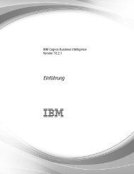
The following illustration shows a server model with twelve 3.5-inch SAS/SATA<br />
hot-swap hard disk drive bays.<br />
Drive bay 1<br />
Drive bay 2<br />
USB 1<br />
connector<br />
USB 2<br />
connector Drive bay 0 Drive bay 3 Drive bay 6 Drive bay 9<br />
Drive bay 4 Drive bay 5 Drive bay 7 Drive bay 8 Drive bay 10<br />
Drive bay 11<br />
Hard disk drive<br />
activity LED (green)<br />
Hard disk drive<br />
status LED (amber)<br />
Power control<br />
button<br />
Power supply<br />
LED<br />
Hard disk drive<br />
activity LED (front panel)<br />
Locator LED<br />
<strong>System</strong> error<br />
LED<br />
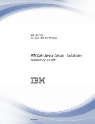
The following illustration shows a server model with twenty-four 2.5-inch SAS/SATA<br />
hot-swap hard disk drive bays.<br />
Hard disk drive<br />
activity LED (green)<br />
Hard disk drive<br />
status LED (amber)<br />
USB 1<br />
connector<br />
USB 2<br />
connector<br />
Drive bay 0 Drive bay 4 Drive bay 8 Drive bay 12 Drive bay 16 Drive bay 20<br />
Drive bay 1 Drive bay 5 Drive bay 9 Drive bay 13 Drive bay 17 Drive bay 21<br />
Drive bay 2 Drive bay 6 Drive bay 10 Drive bay 14 Drive bay 18 Drive bay 22<br />
Drive bay 3 Drive bay 7 Drive bay 11 Drive bay 15 Drive bay 19 Drive bay 23<br />
Power control<br />
button<br />
Power supply<br />
LED<br />
Hard disk drive<br />
activity LED<br />
Locator LED<br />
<strong>System</strong> error<br />
LED<br />
Note: The illustrations in this document might differ slightly from your hardware.<br />
If firmware <strong>and</strong> documentation updates are available, you can download them from<br />
the IBM Web site. The server might have features that are not described in the<br />
documentation that comes with the server, <strong>and</strong> the documentation might be updated<br />
occasionally to include information about those features, or technical updates might<br />
be available to provide additional information that is not included in the server<br />
documentation. To check for updates, complete the following steps.<br />
Note: Changes are made periodically to the IBM Web site. Procedures for locating<br />
firmware <strong>and</strong> documentation might vary slightly from what is described in this<br />
document.<br />
1. Go to http://www.ibm.com/systems/support/.<br />
2. Under Product support, click <strong>System</strong> x.<br />
3. Under Popular links, click Software <strong>and</strong> device drivers for firmware updates,<br />
or click Publications lookup for documentation updates.<br />
Record information about the server in the following table.<br />
Product name IBM <strong>System</strong> <strong>x3630</strong> <strong>M3</strong> server<br />
Machine type <strong>7377</strong><br />
Model number _____________________________________________<br />
Serial number _____________________________________________<br />
2 <strong>System</strong> <strong>x3630</strong> <strong>M3</strong> <strong>Type</strong> <strong>7377</strong>: <strong>Installation</strong> <strong>and</strong> <strong>User</strong>’s <strong>Guide</strong>
The model number <strong>and</strong> serial number are on the pull-out ID label on the bezel, as<br />
shown in the following illustration.<br />
Model number<br />
label<br />
Serial number<br />
label<br />
The IBM Documentation CD<br />
IDlabel<br />
You can download an IBM Server<strong>Guide</strong> Setup <strong>and</strong> <strong>Installation</strong> CD to help you<br />
configure the hardware, install device drivers, <strong>and</strong> install the operating system. For<br />
more information, see “Using the Server<strong>Guide</strong> Setup <strong>and</strong> <strong>Installation</strong> CD” on page<br />
92.<br />
For a list of supported optional devices for the server, see http://www.ibm.com/<br />
servers/eserver/serverproven/compat/us/.<br />
See the Rack <strong>Installation</strong> Instructions document on the IBM Documentation CD for<br />
complete rack installation <strong>and</strong> removal instructions.<br />
The IBM Documentation CD contains documentation for your server in Portable<br />
Document Format (PDF) <strong>and</strong> includes the IBM Documentation Browser to help you<br />
find information quickly.<br />
Hardware <strong>and</strong> software requirements<br />
The IBM Documentation CD requires the following minimum hardware <strong>and</strong><br />
software:<br />
v Microsoft Windows XP, Windows 2000, or Red Hat Linux<br />
v 100 MHz microprocessor<br />
v 32 MB of RAM<br />
v Adobe Acrobat Reader 3.0 (or later) or xpdf, which comes with Linux operating<br />
systems<br />
Using the Documentation Browser<br />
Use the Documentation Browser to browse the contents of the CD, read brief<br />
descriptions of the documents, <strong>and</strong> view documents, using Adobe Acrobat Reader<br />
or xpdf. The Documentation Browser automatically detects the regional settings in<br />
use in your server <strong>and</strong> displays the documents in the language for that region (if<br />
available). If a document is not available in the language for that region, the<br />
English-language version is displayed.<br />
Use one of the following procedures to start the Documentation Browser:<br />
v If Autostart is enabled, insert the CD into the CD or DVD drive. The<br />
Documentation Browser starts automatically.<br />
v If Autostart is disabled or is not enabled for all users, use one of the following<br />
procedures:<br />
– If you are using a Windows operating system, insert the CD into the CD or<br />
DVD drive <strong>and</strong> click Start --> Run. IntheOpen field, type<br />
e:\win32.bat<br />
Chapter 1. The <strong>System</strong> <strong>x3630</strong> <strong>M3</strong> <strong>Type</strong> <strong>7377</strong> server 3
Related documentation<br />
where e is the drive letter of the CD or DVD drive, <strong>and</strong> click OK.<br />
– If you are using Red Hat Linux, insert the CD into the CD or DVD drive; then,<br />
run the following comm<strong>and</strong> from the /mnt/cdrom directory:<br />
sh runlinux.sh<br />
Select your server from the Product menu. The Available Topics list displays all<br />
the documents for your server. Some documents might be in folders. A plus sign (+)<br />
indicates each folder or document that has additional documents under it. Click the<br />
plus sign to display the additional documents.<br />
When you select a document, a description of the document appears under Topic<br />
Description. To select more than one document, press <strong>and</strong> hold the Ctrl key while<br />
you select the documents. Click View Book to view the selected document or<br />
documents in Acrobat Reader or xpdf. If you selected more than one document, all<br />
the selected documents are opened in Acrobat Reader or xpdf.<br />
To search all the documents, type a word or word string in the Search field <strong>and</strong><br />
click Search. The documents in which the word or word string appears are listed in<br />
order of the most occurrences. Click a document to view it, <strong>and</strong> press Crtl+F to use<br />
the Acrobat search function, or press Alt+F to use the xpdf search function within<br />
the document.<br />
Click Help for detailed information about using the Documentation Browser.<br />
This <strong>Installation</strong> <strong>and</strong> <strong>User</strong>’s <strong>Guide</strong> contains general information about the server,<br />
including how to set up the server, how to install supported optional devices, <strong>and</strong><br />
how to configure the server. The following documentation also comes with the<br />
server:<br />
v Warranty Information<br />
This printed document contains the warranty terms <strong>and</strong> a pointer to the IBM<br />
Statement of Limited Warranty on the IBM Web site.<br />
v Safety Information<br />
This document is in PDF on the IBM Documentation CD. It contains translated<br />
caution <strong>and</strong> danger statements. Each caution <strong>and</strong> danger statement that appears<br />
in the documentation has a number that you can use to locate the corresponding<br />
statement in your language in the Safety Information document.<br />
v Rack <strong>Installation</strong> Instructions<br />
This document contains instructions for installing the server in a rack.<br />
v Problem Determination <strong>and</strong> Service <strong>Guide</strong><br />
This document is in PDF on the IBM Documentation CD. It contains information<br />
to help you solve problems yourself, <strong>and</strong> it contains information for service<br />
technicians.<br />
v Environmental Notices <strong>and</strong> <strong>User</strong> <strong>Guide</strong><br />
This document is in PDF on the IBM Documentation CD. It contains translated<br />
environmental notices.<br />
v IBM License Agreement for Machine Code<br />
This document is in PDF on the IBM Documentation CD. It provides translated<br />
versions of the IBM License Agreement for Machine Code for your product.<br />
v Licenses <strong>and</strong> Attributions Documents<br />
This document is in PDF. It contains information about the open-source notices.<br />
4 <strong>System</strong> <strong>x3630</strong> <strong>M3</strong> <strong>Type</strong> <strong>7377</strong>: <strong>Installation</strong> <strong>and</strong> <strong>User</strong>’s <strong>Guide</strong>
Depending on the server model, additional documentation might be included on the<br />
IBM Documentation CD.<br />
The <strong>System</strong> x ® <strong>and</strong> xSeries ® Tools Center is an online information center that<br />
contains information about tools for updating, managing, <strong>and</strong> deploying firmware,<br />
device drivers, <strong>and</strong> operating systems. The <strong>System</strong> x <strong>and</strong> BladeCenter Tools Center<br />
is at http://publib.boulder.ibm.com/infocenter/toolsctr/v1r0/index.jsp.<br />
The server might have features that are not described in the documentation that<br />
comes with the server. The documentation might be updated occasionally to include<br />
information about those features, or technical updates might be available to provide<br />
additional information that is not included in the server documentation. These<br />
updates are available from the IBM Web site. To check for updated documentation<br />
<strong>and</strong> technical updates, complete the following steps.<br />
Note: Changes are made periodically to the IBM Web site. The actual procedure<br />
might vary slightly from what is described in this document.<br />
1. Go to http://www.ibm.com/systems/support/.<br />
2. Under Product support, click <strong>System</strong> x.<br />
3. Under Popular links, click Publications lookup.<br />
4. From the Product family menu, select <strong>System</strong> <strong>x3630</strong> <strong>M3</strong> <strong>and</strong> click Continue.<br />
Chapter 1. The <strong>System</strong> <strong>x3630</strong> <strong>M3</strong> <strong>Type</strong> <strong>7377</strong> server 5
Notices <strong>and</strong> statements in this document<br />
Features <strong>and</strong> specifications<br />
The caution <strong>and</strong> danger statements in this document are also in the multilingual<br />
Safety Information document, which is on the Documentation CD. Each statement is<br />
numbered for reference to the corresponding statement in your language in the<br />
Safety Information document.<br />
The following notices <strong>and</strong> statements are used in this document:<br />
v Note: These notices provide important tips, guidance, or advice.<br />
v Important: These notices provide information or advice that might help you avoid<br />
inconvenient or problem situations.<br />
v Attention: These notices indicate potential damage to programs, devices, or<br />
data. An attention notice is placed just before the instruction or situation in which<br />
damage might occur.<br />
v Caution: These statements indicate situations that can be potentially hazardous<br />
to you. A caution statement is placed just before the description of a potentially<br />
hazardous procedure step or situation.<br />
v Danger: These statements indicate situations that can be potentially lethal or<br />
extremely hazardous to you. A danger statement is placed just before the<br />
description of a potentially lethal or extremely hazardous procedure step or<br />
situation.<br />
The following information is a summary of the features <strong>and</strong> specifications of the<br />
server. Depending on the model, some features might not be available, or some<br />
specifications might not apply.<br />
Racks are marked in vertical increments of 4.45 cm (1.75 inches). Each increment<br />
is referred to as a unit, or “U.” A 1-U-high device is 1.75 inches tall.<br />
Notes:<br />
1. Power consumption <strong>and</strong> heat output vary depending on the number <strong>and</strong> type of<br />
optional features that are installed <strong>and</strong> the power-management optional features<br />
that are in use.<br />
2. The sound levels were measured in controlled acoustical environments<br />
according to the procedures specified by the American National St<strong>and</strong>ards<br />
Institute (ANSI) S12.10 <strong>and</strong> ISO 7779 <strong>and</strong> are reported in accordance with ISO<br />
9296. Actual sound-pressure levels in a given location might exceed the<br />
average values stated because of room reflections <strong>and</strong> other nearby noise<br />
sources. The declared sound-power levels indicate an upper limit, below which<br />
a large number of computers will operate.<br />
6 <strong>System</strong> <strong>x3630</strong> <strong>M3</strong> <strong>Type</strong> <strong>7377</strong>: <strong>Installation</strong> <strong>and</strong> <strong>User</strong>’s <strong>Guide</strong>
Table 1. Features <strong>and</strong> specifications<br />
Microprocessor:<br />
v Supports multi-core Intel Xeon<br />
microprocessors, with integrated<br />
memory controller <strong>and</strong> Quick Path<br />
Interconnect (QPI) architecture<br />
v Designed for LGA 1366 socket<br />
v Scalable up to six cores<br />
v 32 KB instruction cache, 32 KB data<br />
cache, <strong>and</strong> up to 12 MB L3 cache that is<br />
shared among the cores<br />
v Support for Intel Extended Memory 64<br />
Technology (EM64T)<br />
Note:<br />
v Do not install an Intel Xeon 5500<br />
series microprocessor <strong>and</strong> an Xeon <br />
5600 series microprocessor in the same<br />
server.<br />
v Use the Setup utility to determine the<br />
type <strong>and</strong> speed of the microprocessors.<br />
v For a list of supported microprocessors,<br />
see http://www.ibm.com/servers/eserver/<br />
serverproven/compat/us/.<br />
Memory:<br />
v Twelve DIMM connectors (six per<br />
microprocessor)<br />
v Minimum: 1 GB DIMM per<br />
microprocessor<br />
v Maximum: 96 GB<br />
v <strong>Type</strong>: PC3-10600-999 800, 1066, <strong>and</strong><br />
1333 MHz, ECC, DDR3 registered<br />
SDRAM DIMMs only<br />
v Sizes: 1 GB single-rank, 2 GB<br />
single-rank or dual-rank, 4 GB<br />
single-rank or dual-rank, 8 GB dual-rank,<br />
<strong>and</strong> 16 GB quad-rank<br />
v Chipkill supported<br />
Expansion bays (depending on the<br />
model):<br />
v Twelve 3.5-inch SAS/SATA hot-swap<br />
hard disk drive bays with option to add<br />
two more rear 3.5-inch SAS/SATA<br />
hot-swap hard disk drive bays<br />
v Twenty-four 2.5-inch SAS/SATA<br />
hot-swap hard disk drive bays with<br />
option to add four more rear 2.5-inch<br />
SAS/SATA hot-swap hard disk drive<br />
bays<br />
PCI Expansion slots: Supports three PCI<br />
expansion slots:<br />
v One PCIe2 Express x16 slot, x8<br />
electrical wired<br />
v One PCIe2 Express x16 slot, x4<br />
electrical wired<br />
v One PCIe2 Express x8 slot, x8 electrical<br />
wired (internal only)<br />
Integrated functions:<br />
v Integrated management module (IMM),<br />
which provides service processor<br />
control <strong>and</strong> monitoring functions, video<br />
controller, <strong>and</strong> (when the optional<br />
virtual media key is installed) remote<br />
keyboard, video, mouse, <strong>and</strong> remote<br />
hard disk drive capabilities<br />
v Integrated SATA controller<br />
v Serial over LAN (SOL) <strong>and</strong> serial<br />
redirection over Telnet or Secure Shell<br />
(SSH)<br />
v One systems-management RJ-45<br />
10/100 Ethernet interface for<br />
connection to a dedicated<br />
systems-management network<br />
v Support for remote management<br />
presence through an optional virtual<br />
media key<br />
v One Intel dual-port 10/100/1000<br />
Ethernet controller with Wake on LAN<br />
support; also support one port as<br />
share-nic for system-management<br />
v One serial port, provided by the<br />
integrated management module (IMM)<br />
v Five Universal Serial Bus (USB) ports<br />
(two on front, two on rear of server,<br />
<strong>and</strong> one internal for an optional USB<br />
flash device)<br />
v One video port on rear of server<br />
Note: Maximum video resolution is<br />
1600 x 1200 at 85 Hz.<br />
v Support for optional hypervisor function<br />
Note: In messages <strong>and</strong> documentation,<br />
the term service processor refers to the<br />
integrated management module (IMM).<br />
Video controller:<br />
v Matrox G200eV video on system board<br />
v Compatible with SVGA <strong>and</strong> VGA<br />
v DDR2-250MHz SDRAM video memory<br />
controller<br />
v Video memory is not exp<strong>and</strong>able<br />
v Avocent digital video compression<br />
RAID (depending on the model):<br />
v ServeRAID-M1015 SAS/SATA adapter<br />
that provides RAID levels 0, 1, <strong>and</strong> 10<br />
with optional RAID 5/50 <strong>and</strong> SED (Self<br />
Encrypting Disk) upgrade<br />
v Using ServeRAID-M1015 SAS/SATA<br />
adapter in 2.5-inch model with 28 hard<br />
disk drives, only 16 hard disk drives can<br />
be configured as RAID as rest of 12 hard<br />
disk drives are in JBOD state<br />
v ServeRAID-M5014 SAS/SATA adapter<br />
that provides RAID levels 0, 1, 10, 5, <strong>and</strong><br />
50 with <strong>and</strong> RAID 6/60 <strong>and</strong> SED upgrade<br />
(256 MB cache, with optional battery<br />
backup)<br />
v ServeRAID-M5015 SAS/SATA adapter<br />
that provides RAID levels 0, 1, 10, 5, <strong>and</strong><br />
50 with optional RAID 6/60 <strong>and</strong> SED<br />
upgrade (512 MB cache, with optional<br />
battery backup)<br />
Environment:<br />
v Air temperature:<br />
– Server on: 10°C to 35°C (50°F to<br />
95°F); altitude: 0 to 915 m (3000 ft).<br />
– Server on: 10°C to 32°C (50°F to<br />
90°F); altitude: 915 m (3000 ft) to<br />
2134 m (7000 ft).<br />
– Server on: 10°C to 28°C (50°F to<br />
83°F); altitude: 2134 m (7000 ft) to<br />
3050 m (10000 ft).<br />
– Server off: 5°C to 45°C (41°F to<br />
113°F)<br />
– Shipping: -40°C to 60°C (-40°F to<br />
140°F)<br />
v Humidity:<br />
– Server on: 20% to 80%; maximum<br />
dew point: 21°C; maximum rate of<br />
change: 5 °C/hr<br />
– Server off: 8% to 80%; maximum dew<br />
point: 27°C<br />
– Shipment: 5% to 100%<br />
v Particulate contamination:<br />
Attention: Airborne particulates <strong>and</strong><br />
reactive gases acting alone or in<br />
combination with other environmental<br />
factors such as humidity or temperature<br />
might pose a risk to the server. For<br />
information about the limits for<br />
particulates <strong>and</strong> gases, see “Particulate<br />
contamination” on page 109.<br />
Chapter 1. The <strong>System</strong> <strong>x3630</strong> <strong>M3</strong> <strong>Type</strong> <strong>7377</strong> server 7
Table 1. Features <strong>and</strong> specifications (continued)<br />
Electrical input with hot-swap ac power<br />
supplies:<br />
v Sine-wave input (50 - 60 Hz) required<br />
v Input voltage range automatically<br />
selected<br />
v Input voltage low range:<br />
– Minimum: 100 V ac<br />
– Maximum: 127 V ac<br />
v Input voltage high range:<br />
– Minimum: 200 V ac<br />
– Maximum: 240 V ac<br />
v Input kilovolt-amperes (kVA)<br />
approximately:<br />
– Minimum: 0.22 kVA<br />
– Maximum: 0.78 kVA<br />
What your server offers<br />
Size:<br />
v 2U<br />
v Height: 86.5 mm (3.406 in.)<br />
v Depth:<br />
– EIA flange to rear: 719.39 mm<br />
(28.32 in.)<br />
– Overall: 749.39 mm (29.5 in.)<br />
v Width:<br />
– With top cover: 447 mm (17.598 in.)<br />
– With front bezel: 487.995 mm<br />
(19.212 in.)<br />
v Weight: approximately 16.20 kg (35.64<br />
lb) to 29.20 kg (64.24 lb) depending on<br />
your configuration<br />
<strong>System</strong> fans: Up to four<br />
Hot-swap power supplies (depending<br />
on the model):<br />
v Up to two hot-swap power supplies for<br />
redundancy support<br />
– 675-watt ac<br />
– 675-watt high-efficiency ac<br />
Note: You cannot mix high-efficiency <strong>and</strong><br />
non-high-efficiency power supplies in the<br />
server.<br />
Acoustical noise emissions:<br />
v Declared sound power, idle: 6.6 bel<br />
v Declared sound power, operating: 6.6 bel<br />
Heat output:Approximate heat output:<br />
v Minimum configuration: 762 Btu per hour<br />
(223 watts)<br />
v Maximum configuration: 2662 Btu per<br />
hour (780 watts)<br />
The server uses the following features <strong>and</strong> technologies:<br />
v UEFI-compliant server firmware<br />
IBM <strong>System</strong> x Server Firmware offers several features, including Unified<br />
Extensible Firmware Interface (UEFI) 2.1 compliance, Active Energy Manager<br />
technology, enhanced RAS capabilities, <strong>and</strong> BIOS compatibility support. UEFI<br />
replaces the basic input/output system (BIOS) <strong>and</strong> defines a st<strong>and</strong>ard interface<br />
between the operating system, platform firmware, <strong>and</strong> external devices.<br />
UEFI-compliant <strong>System</strong> x servers are capable of booting UEFI-compliant<br />
operating systems, BIOS-based operating systems, <strong>and</strong> BIOS-based adapters as<br />
well as UEFI-compliant adapters.<br />
Note: The server does not support DOS.<br />
v Integrated management module<br />
The integrated management module (IMM) combines service processor<br />
functions, video controller, <strong>and</strong> (when an optional virtual media key is installed)<br />
remote presence function in a single chip. The IMM provides advanced<br />
service-processor control, monitoring, <strong>and</strong> alerting function. If an environmental<br />
condition exceeds a threshold or if a system component fails, the IMM lights<br />
LEDs to help you diagnose the problem, records the error in the event log, <strong>and</strong><br />
alerts you to the problem. Optionally, the IMM also provides a virtual presence<br />
capability for remote server management capabilities. The IMM provides remote<br />
server management through industry-st<strong>and</strong>ard interfaces:<br />
– Intelligent Platform Management Interface (IPMI) version 2.0<br />
– Simple Network Management Protocol (SNMP) version 3<br />
– Common Information Model (CIM)<br />
– Web browser<br />
8 <strong>System</strong> <strong>x3630</strong> <strong>M3</strong> <strong>Type</strong> <strong>7377</strong>: <strong>Installation</strong> <strong>and</strong> <strong>User</strong>’s <strong>Guide</strong>
v Remote presence capability <strong>and</strong> blue-screen capture<br />
The optional virtual media key is required to enable the remote presence <strong>and</strong><br />
blue-screen capture features. The remote presence feature provides the following<br />
functions:<br />
– Remotely viewing video with graphics resolutions up to 1600 x 1200 at 85 Hz,<br />
regardless of the system state<br />
– Remotely accessing the server, using the keyboard <strong>and</strong> mouse from a remote<br />
client<br />
– Mapping the CD or DVD drive, diskette drive, <strong>and</strong> USB flash drive on a<br />
remote client, <strong>and</strong> mapping ISO <strong>and</strong> diskette image files as virtual drives that<br />
are available for use by the server<br />
– Uploading a diskette image to the IMM memory <strong>and</strong> mapping it to the server<br />
as a virtual drive<br />
The blue-screen capture feature captures the video display contents before the<br />
IMM restarts the server when the IMM detects an operating-system hang<br />
condition. A system administrator can use the blue-screen capture to assist in<br />
determining the cause of the hang condition.<br />
v IBM Dynamic <strong>System</strong> Analysis Preboot diagnostics programs<br />
The Dynamic <strong>System</strong> Analysis (DSA) Preboot diagnostics programs are stored<br />
on the integrated USB memory. It collects <strong>and</strong> analyzes system information to aid<br />
in diagnosing server problems. The diagnostic programs collect the following<br />
information about the server:<br />
– <strong>System</strong> configuration<br />
– Network interfaces <strong>and</strong> settings<br />
– Installed hardware<br />
– Light path diagnostics status<br />
– Service processor status <strong>and</strong> configuration<br />
– Vital product data, firmware, <strong>and</strong> UEFI configuration<br />
– Hard disk drive health<br />
– RAID controller configuration<br />
– Event logs for ServeRAID controllers <strong>and</strong> service processors<br />
The diagnostic programs create a merged log that includes events from all<br />
collected logs. The information is collected into a file that you can send to IBM<br />
service <strong>and</strong> support. Additionally, you can view the information locally through a<br />
generated text report file. You can also copy the log to a removable media <strong>and</strong><br />
view the log from a Web browser.<br />
For additional information about DSA Preboot diagnostics, see the Problem<br />
Determination <strong>and</strong> Service <strong>Guide</strong> on the IBM Documentation CD<br />
v IBM <strong>System</strong>s Director<br />
IBM <strong>System</strong>s Director is a workgroup-hardware-management tool that you can<br />
use to centrally manage <strong>System</strong> x <strong>and</strong> xSeries servers. For more information,<br />
see the IBM <strong>System</strong>s Director documentation on the IBM <strong>System</strong>s Director CD.<br />
v Active Energy Manager<br />
The Active Energy Manager solution is an IBM <strong>System</strong>s Director extension that<br />
measures <strong>and</strong> reports server power consumption as it occurs. This enables you<br />
to monitor power consumption in correlation to specific software application<br />
programs <strong>and</strong> hardware configurations. You can obtain the measurement values<br />
through the systems-management interface <strong>and</strong> view them, using IBM <strong>System</strong>s<br />
Chapter 1. The <strong>System</strong> <strong>x3630</strong> <strong>M3</strong> <strong>Type</strong> <strong>7377</strong> server 9
Director. For more information, see the IBM Director documentation on the IBM<br />
<strong>System</strong>s Director CD, or see http://www.ibm.com/systems/management/director/<br />
extensions/actengmrg.html.<br />
v IBM X-Architecture technology<br />
IBM X-Architecture technology combines proven, innovative IBM designs to make<br />
your Intel-processor-based server powerful, scalable, <strong>and</strong> reliable. For more<br />
information, see http://www.ibm.com/servers/eserver/xseries/xarchitecture/<br />
enterprise/index.html.<br />
– Active Memory <br />
The Active Memory feature improves the reliability of memory through<br />
memory mirroring. Memory mirroring stores data in two pairs of DIMMs<br />
simultaneously.<br />
– Large system-memory capacity<br />
The memory bus supports up to 96 GB of system memory. The memory<br />
controller supports error correcting code (ECC) for up to 12 industry-st<strong>and</strong>ard<br />
PC3-10600R-999 (single-rank or dual-rank), 800, 1066, <strong>and</strong> 1333 MHz, DDR3<br />
(third-generation double-data-rate), registered, synchronous dynamic r<strong>and</strong>om<br />
access memory (SDRAM) dual inline memory modules (DIMMs).<br />
v IBM Server<strong>Guide</strong> Setup <strong>and</strong> <strong>Installation</strong> CD<br />
The Server<strong>Guide</strong> Setup <strong>and</strong> <strong>Installation</strong> CD, which you can download from the<br />
Web, provides programs to help you set up the server <strong>and</strong> install a Windows<br />
operating system. The Server<strong>Guide</strong> program detects installed optional hardware<br />
devices <strong>and</strong> provides the correct configuration programs <strong>and</strong> device drivers. For<br />
more information about the Server<strong>Guide</strong> Setup <strong>and</strong> <strong>Installation</strong> CD, see “Using<br />
the Server<strong>Guide</strong> Setup <strong>and</strong> <strong>Installation</strong> CD” on page 92.<br />
v Integrated network support<br />
The server comes with one integrated Intel Gigabit Ethernet controller, which<br />
supports connection to a 10 Mbps, 100 Mbps, or 1000 Mbps network. For more<br />
information, see “Configuring the Gigabit Ethernet controller” on page 97.<br />
v Large data-storage <strong>and</strong> hot-swap capability<br />
The server supports up to twelve 3.5-inch or twenty-four 2.5-inch SAS/SATA<br />
hot-swap hard disk drive (depending on the model). With the hot-swap feature,<br />
you can add, remove, or replace hard disk drives without turning off the server.<br />
v Light path diagnostics<br />
Light path diagnostics provides LEDs to help you diagnose problems. For more<br />
information, see the section about light path diagnostics in the Problem<br />
Determination <strong>and</strong> Service <strong>Guide</strong>.<br />
v PCI adapter capabilities<br />
The server supports up to three PCI expansion slots. For more information, see<br />
“Installing an adapter” on page 37.<br />
v Memory mirroring<br />
Memory mirroring improves the availability of memory by writing information to<br />
the main memory <strong>and</strong> redundant locations in a mirrored pair of DIMMs.<br />
v Redundant power capabilities<br />
The server supports up to two power supplies, which provide redundancy <strong>and</strong><br />
hot-swap capability for a typical configuration. If the maximum load on the server<br />
is less than that provided by the power supplies <strong>and</strong> a problem occurs with one<br />
of the power supplies, the other power supply can meet the power requirements.<br />
If the maximum load on the server is greater than 675 watts <strong>and</strong> a problem<br />
10 <strong>System</strong> <strong>x3630</strong> <strong>M3</strong> <strong>Type</strong> <strong>7377</strong>: <strong>Installation</strong> <strong>and</strong> <strong>User</strong>’s <strong>Guide</strong>
occurs with one of the power supplies, Active Energy Manager can act to<br />
minimize the load somewhat so that the server can function with the remaining<br />
power supply.<br />
Note: You cannot mix high-efficiency <strong>and</strong> non-high-efficiency power supplies in<br />
the server.<br />
v RAID support<br />
Depending on the model, your IBM <strong>System</strong> <strong>x3630</strong> <strong>M3</strong> server implements<br />
redundant array of independent disks (RAID) through software or hardware.<br />
A ServeRAID adapter provides hardware RAID support to create configurations.<br />
Depending on the server model, your server may come with a st<strong>and</strong>ard RAID<br />
adapter that provides RAID levels 0, 1, 1E, or above. An optional RAID adapter<br />
is available for purchase.<br />
v <strong>System</strong>s-management capabilities<br />
The server contains an integrated management module (IMM) which enables you<br />
to manage the functions of the server locally <strong>and</strong> remotely. The addition of the<br />
optional IBM Virtual Media Key provides remote presence <strong>and</strong> blue-screen<br />
capture capability. The IMM also provides system monitoring, event recording,<br />
<strong>and</strong> dial-out alert capability.<br />
Reliability, availability, <strong>and</strong> serviceability features<br />
Three important computer design features are reliability, availability, <strong>and</strong><br />
serviceability (RAS). The RAS features help to ensure the integrity of the data that<br />
is stored in the server, the availability of the server when you need it, <strong>and</strong> the ease<br />
with which you can diagnose <strong>and</strong> repair problems.<br />
The server has the following RAS features:<br />
v Automatic error retry <strong>and</strong> recovery<br />
v Automatic restart after a power failure<br />
v Built-in monitoring for fan, power, temperature, voltage, <strong>and</strong> power-supply<br />
redundancy<br />
v Cable-presence detection on most connectors<br />
v Chipkill memory protection<br />
v Dual redundant UEFI server firmware images<br />
v Error codes <strong>and</strong> messages<br />
v Error correcting code (ECC) L2 cache <strong>and</strong> system memory<br />
v Cooling fans with speed-sensing capability<br />
v Hot-swap hard disk drives<br />
v Information <strong>and</strong> light path diagnostics LED panels<br />
v Integrated management module (service processor)<br />
v Memory mirroring<br />
v Menu-driven setup, system configuration, <strong>and</strong> redundant array of independent<br />
disks (RAID) configuration programs<br />
v Parity checking or CRC checking on the serially-attached SCSI (SAS) bus <strong>and</strong><br />
PCI buses<br />
v Power management: compliance with Advanced Configuration <strong>and</strong> Power<br />
Interface (ACPI)<br />
v Power-on self-test (POST)<br />
v Predictive Failure Analysis (PFA) alerts on memory, SAS/SATA hard disk drives,<br />
fans, <strong>and</strong> power supplies<br />
v Redundant Ethernet capabilities with failover support<br />
v Redundant hot-swap power supplies<br />
v Remote system problem-determination support<br />
v St<strong>and</strong>by voltage for systems-management features <strong>and</strong> monitoring<br />
Chapter 1. The <strong>System</strong> <strong>x3630</strong> <strong>M3</strong> <strong>Type</strong> <strong>7377</strong> server 11
IBM <strong>System</strong>s Director<br />
v Startup (boot) from LAN through Preboot Execution Environment (PXE) boot<br />
agent utility or Dynamic Host Configuration Protocol/Boot Protocol<br />
(DHCP/BOOTP)<br />
v <strong>System</strong> auto-configuring from the configuration menu<br />
v <strong>System</strong> error logging (POST <strong>and</strong> service processor)<br />
v <strong>System</strong>s-management monitoring through the Inter-Integrated Circuit (I 2 C) bus<br />
v Upgradeable POST, UEFI, diagnostics, service processor microcode, <strong>and</strong><br />
read-only memory (ROM) resident code, locally or over the LAN<br />
v Vital product data (VPD) on microprocessors, system board, power supplies, <strong>and</strong><br />
SAS (hot-swap-drive) backplane<br />
v Wake on LAN capability<br />
IBM <strong>System</strong>s Director is a platform-management foundation that streamlines the<br />
way you manage physical <strong>and</strong> virtual systems in a heterogeneous environment. By<br />
using industry st<strong>and</strong>ards, IBM <strong>System</strong>s Director supports multiple operating systems<br />
<strong>and</strong> virtualization technologies in IBM <strong>and</strong> non-IBM x86 platforms.<br />
Through a single user interface, IBM <strong>System</strong>s Director provides consistent views for<br />
viewing managed systems, determining how these systems relate to one another,<br />
<strong>and</strong> identifying their statuses, helping to correlate technical resources with business<br />
needs. A set of common tasks that are included with IBM <strong>System</strong>s Director provides<br />
many of the core capabilities that are required for basic management, which means<br />
instant out-of-the-box business value. These common tasks include discovery,<br />
inventory, configuration, system health, monitoring, updates, event notification, <strong>and</strong><br />
automation for managed systems.<br />
The IBM <strong>System</strong>s Director Web <strong>and</strong> comm<strong>and</strong>-line interfaces provide a consistent<br />
interface that is focused on driving these common tasks <strong>and</strong> capabilities:<br />
v Discovering, navigating, <strong>and</strong> visualizing systems on the network with the detailed<br />
inventory <strong>and</strong> relationships to the other network resources<br />
v Notifying users of problems that occur on systems <strong>and</strong> the ability to isolate the<br />
sources of the problems<br />
v Notifying users when systems need updates <strong>and</strong> distributing <strong>and</strong> installing<br />
updates on a schedule<br />
v Analyzing real-time data for systems <strong>and</strong> setting critical thresholds that notify the<br />
administrator of emerging problems<br />
v Configuring settings of a single system <strong>and</strong> creating a configuration plan that can<br />
apply those setting to multiple systems<br />
v Updating installed plug-ins to add new features <strong>and</strong> functions to the base<br />
capabilities<br />
v Managing the life cycles of virtual resources<br />
For more information about IBM <strong>System</strong>s Director, see the documentation on the<br />
IBM <strong>System</strong>s Director DVD that comes with the server <strong>and</strong> the IBM xSeries<br />
<strong>System</strong>s Management Web page at http://www.ibm.com/systems/management/,<br />
which presents an overview of IBM <strong>System</strong>s Management <strong>and</strong> IBM <strong>System</strong>s<br />
Director.<br />
12 <strong>System</strong> <strong>x3630</strong> <strong>M3</strong> <strong>Type</strong> <strong>7377</strong>: <strong>Installation</strong> <strong>and</strong> <strong>User</strong>’s <strong>Guide</strong>
The UpdateXpress <strong>System</strong> Pack Installer<br />
The UpdateXpress <strong>System</strong> Pack Installer detects supported <strong>and</strong> installed device<br />
drivers <strong>and</strong> firmware in the server <strong>and</strong> installs available updates. For additional<br />
information <strong>and</strong> to download the UpdateXpress <strong>System</strong> Pack Installer, go to the<br />
<strong>System</strong> x <strong>and</strong> BladeCenter Tools Center at http://publib.boulder.ibm.com/infocenter/<br />
toolsctr/v1r0/index.jsp <strong>and</strong> click UpdateXpress <strong>System</strong> Pack Installer.<br />
Server controls, LEDs, <strong>and</strong> power<br />
Front view<br />
This section describes the controls <strong>and</strong> light-emitting diodes (LEDs) <strong>and</strong> how to turn<br />
the server on <strong>and</strong> off.<br />
The following illustration shows the controls, connectors, LEDs, <strong>and</strong> hard disk drive<br />
bays on the front of the server.<br />
Drive bay 1<br />
Drive bay 2<br />
USB 1<br />
connector<br />
USB 2<br />
connector Drive bay 0 Drive bay 3 Drive bay 6 Drive bay 9<br />
Drive bay 4 Drive bay 5 Drive bay 7 Drive bay 8 Drive bay 10<br />
Drive bay 11<br />
Hard disk drive<br />
activity LED (green)<br />
Hard disk drive<br />
status LED (amber)<br />
Power control<br />
button<br />
Power supply<br />
LED<br />
Hard disk drive<br />
activity LED (front panel)<br />
Locator LED<br />
<strong>System</strong> error<br />
LED<br />
USB connectors: Connect a USB device, such as USB mouse or keyboard to<br />
either of these connectors.<br />
Hard disk drive activity LED (front panel): When this LED is flashing, it indicates<br />
that the drive is in use. This function is reserved for simple-swap models. For<br />
existing models, please see the hot-swap hard disk drive activity <strong>and</strong> status LEDs<br />
(green <strong>and</strong> amber) that pass from the backplane as the indicators for any activity or<br />
warning.<br />
Hard disk drive status LED (amber): This amber LED is used on hot-swap<br />
SAS/SATA hard disk drives. Each hot-swap hard disk drive has a status LED. When<br />
this LED is lit, it indicates that the drive has failed. When this LED is flashing slowly<br />
(one flash per second), it indicates that the drive is being rebuilt as part of a RAID<br />
configuration. When the LED is flashing rapidly (three flashes per second), it<br />
indicates that the controller is identifying the drive.<br />
Operator information panel: This panel contains the power control button <strong>and</strong><br />
light-emitting diodes (LEDs).<br />
Power-control button <strong>and</strong> power-on LED: Press this button to turn the server on<br />
<strong>and</strong> off manually or to wake the server from a reduced-power state. The states of<br />
the green power-on LED are as follows:<br />
Off: AC power is not present, or the power supply or the LED itself has failed.<br />
Chapter 1. The <strong>System</strong> <strong>x3630</strong> <strong>M3</strong> <strong>Type</strong> <strong>7377</strong> server 13
Rear view<br />
Flashing rapidly (4 times per second): The server is turned off <strong>and</strong> is not<br />
ready to be turned on. The power-control button is disabled. This will last<br />
approximately 20 to 40 seconds.<br />
Flashing slowly (once per second): The server is turned off <strong>and</strong> is ready to be<br />
turned on. You can press the power-control button to turn on the server.<br />
Lit: The server is turned on.<br />
Fading on <strong>and</strong> off: The server is in a reduced-power state. To wake the server,<br />
press the power-control button or use the IMM Web interface. See “Logging on<br />
to the Web interface” on page 97 for information on logging on to the IMM Web<br />
interface.<br />
Hard disk drive activity LED (green): When this LED is flashing, it indicates that<br />
the drive is in use.<br />
Locator LED: Use this blue LED to visually locate the server among other servers.<br />
You can use IBM <strong>System</strong>s Director to light this LED remotely. This LED is controlled<br />
by the IMM.<br />
<strong>System</strong>-error LED: When this amber LED is lit, it indicates that a system error has<br />
occurred. This LED is controlled by the IMM.<br />
The following illustration shows the connectors on the rear of the server.<br />
Power<br />
supply 1<br />
AC<br />
DC<br />
Power cord<br />
connectors<br />
Power<br />
supply 2<br />
AC<br />
DC<br />
Optional SAS/SATA<br />
hard disk drives<br />
NMI button Serial<br />
connector<br />
Video<br />
connector<br />
USB 3 & 4<br />
connectors<br />
<strong>System</strong> management<br />
Ethernet connector<br />
Ethernet 1& 2<br />
connectors<br />
Ethernet connectors: Use any of these connectors to connect the server to a<br />
network. When you use the Ethernet 1 connector, the network can be shared with<br />
the IMM through a single network cable.<br />
Power-cord connector: Connect the power cord to this connector.<br />
Note: Power supply 1 is the default/primary power supply. If the server has two<br />
power supplies <strong>and</strong> if any of the power supplies fails, the server will not have<br />
redundant power <strong>and</strong> you must replace the power supply immediately.<br />
USB connectors: Connect a USB device, such as USB mouse or keyboard to<br />
either of these connectors.<br />
NMI button: Press this button to force a nonmaskable interrupt to the<br />
microprocessor. You might have to use a pen or the end of a straightened paper<br />
clip to press the button. It allows you to blue screen the server <strong>and</strong> take a memory<br />
dump (use this button only when directed by the IBM service support).<br />
14 <strong>System</strong> <strong>x3630</strong> <strong>M3</strong> <strong>Type</strong> <strong>7377</strong>: <strong>Installation</strong> <strong>and</strong> <strong>User</strong>’s <strong>Guide</strong>
Serial connector: Connect a 9-pin serial device to this connector. The serial port is<br />
shared with the integrated management module (IMM). The IMM can take control of<br />
the shared serial port to perform text console redirection <strong>and</strong> to redirect serial<br />
traffic, using Serial over LAN (SOL).<br />
Video connector: Connect a monitor to this connector. The video connectors on<br />
the front <strong>and</strong> rear of the server can be used simultaneously.<br />
Note: The maximum video resolution is 1600 x 1200 at 85 Hz.<br />
<strong>System</strong>s-management Ethernet connector: Use this connector to connect the<br />
server to a network for systems-management information control. This connector is<br />
used only by the IMM.<br />
The following illustration shows the LEDs on the rear of the server.<br />
AC power<br />
LED<br />
DC power<br />
LED<br />
Power-supply<br />
error LED<br />
AC<br />
DC<br />
AC<br />
DC<br />
Ethernet activity<br />
LED<br />
Ethernet link<br />
LED<br />
Ethernet activity LEDs: When these LEDs are lit, they indicate that the server is<br />
transmitting to or receiving signals from the Ethernet LAN that is connected to the<br />
Ethernet port.<br />
Ethernet link LEDs: When these LEDs are lit, they indicate that there is an active<br />
link connection on the 10BASE-T, 100BASE-TX, or 1000BASE-TX interface for the<br />
Ethernet port.<br />
AC power LED: Each hot-swap power supply has an ac power LED <strong>and</strong> a dc<br />
power LED. When the ac power LED is lit, it indicates that sufficient power is<br />
coming into the power supply through the power cord. During typical operation, both<br />
the ac <strong>and</strong> dc power LEDs are lit. For any other combination of LEDs, see<br />
“Power-supply LEDs.”<br />
DC power LED: Each hot-swap power supply has a dc power LED <strong>and</strong> an ac<br />
power LED. When the dc power LED is lit, it indicates that the power supply is<br />
supplying adequate dc power to the system. During typical operation, both the ac<br />
<strong>and</strong> dc power LEDs are lit. For any other combination of LEDs, see “Power-supply<br />
LEDs.”<br />
Power-supply error LED: When the power-supply error LED is lit, it indicates that<br />
the power supply has failed.<br />
Power-supply LEDs<br />
The following illustration shows the power-supply LEDs on the rear of the server.<br />
For more information about solving power-supply problems, see the Problem<br />
Determination <strong>and</strong> Service <strong>Guide</strong>.<br />
Chapter 1. The <strong>System</strong> <strong>x3630</strong> <strong>M3</strong> <strong>Type</strong> <strong>7377</strong> server 15
AC power<br />
LED<br />
DC power<br />
LED<br />
Power-supply<br />
error LED<br />
AC<br />
DC<br />
AC<br />
DC<br />
AC<br />
DC<br />
The following table describes the problems that are indicated by various<br />
combinations of the power-supply LEDs <strong>and</strong> suggested actions to correct the<br />
detected problems.<br />
Table 2. Power-supply LEDs<br />
Power-supply LEDs<br />
AC DC Error<br />
(green) (green) (amber) Description Action Notes<br />
On On Off Normal operation<br />
Off Off Off No ac power to<br />
the server or a<br />
problem with the<br />
ac power source<br />
1.<br />
2.<br />
Check the ac power to the server.<br />
Make sure that the power cord is<br />
connected to a functioning power<br />
source.<br />
This is a normal<br />
condition when no<br />
ac power is present.<br />
3. Turn the server off <strong>and</strong> then turn the<br />
server back on.<br />
4. If the problem remains, replace the<br />
power supply.<br />
Off Off On No ac power to<br />
the server or a<br />
problem with the<br />
ac power source<br />
<strong>and</strong> the power<br />
supply had<br />
detected an<br />
internal problem<br />
Off On Off Faulty power<br />
supply<br />
Off On On Faulty power<br />
supply<br />
On Off Off Power supply not<br />
fully seated,<br />
faulty system<br />
board, or faulty<br />
power supply<br />
On Off or<br />
Flashing<br />
On Faulty power<br />
supply<br />
On On On Power supply is<br />
faulty but still<br />
operational<br />
16 <strong>System</strong> <strong>x3630</strong> <strong>M3</strong> <strong>Type</strong> <strong>7377</strong>: <strong>Installation</strong> <strong>and</strong> <strong>User</strong>’s <strong>Guide</strong><br />
1. Replace the power supply.<br />
2. Make sure that the power cord is<br />
connected to a functioning power<br />
source.<br />
Replace the power supply.<br />
Replace the power supply.<br />
1. Reseat the power supply.<br />
2. Replace the power supply.<br />
3. (Trained service technician only)<br />
Replace the system board.<br />
Replace the power supply.<br />
Replace the power supply.<br />
This happens only<br />
when a second<br />
power supply is<br />
providing power to<br />
the server.<br />
Typically indicates<br />
that a power supply<br />
is not fully seated.
Server power features<br />
When the server is connected to a power source but is not turned on, the operating<br />
system does not run, <strong>and</strong> all core logic except for the integrated management<br />
module (IMM) is shut down; however, the server can respond to requests from the<br />
IMM, such as a remote request to turn on the server. The power-on LED flashes to<br />
indicate that the server is connected to power but is not turned on.<br />
Turning on the server<br />
Approximately 40 seconds after the server is connected to power, the power-control<br />
button becomes active, <strong>and</strong> one or more fans might start running to provide cooling<br />
while the server is connected to power. You can turn on the server <strong>and</strong> start the<br />
operating system by pressing the power-control button.<br />
The server can also be turned on in any of the following ways:<br />
v If a power failure occurs while the server is turned on, the server will restart<br />
automatically when power is restored.<br />
v If your operating system supports the Wake on LAN feature, the Wake on LAN<br />
feature can turn on the server.<br />
For 32-bit operating systems only: Some memory is reserved for various system<br />
resources <strong>and</strong> is unavailable to the operating system. The amount of memory that<br />
is reserved for system resources depends on the operating system, the<br />
configuration of the server, <strong>and</strong> the configured PCI options.<br />
Turning off the server<br />
When you turn off the server <strong>and</strong> leave it connected to power, the server can<br />
respond to requests from the IMM, such as a remote request to turn on the server.<br />
While the server remains connected to power, one or more fans might continue to<br />
run. To remove all power from the server, you must disconnect it from the power<br />
source.<br />
Some operating systems require an orderly shutdown before you turn off the server.<br />
See your operating-system documentation for information about shutting down the<br />
operating system.<br />
Statement 5:<br />
CAUTION:<br />
The power control button on the device <strong>and</strong> the power switch on the power<br />
supply do not turn off the electrical current supplied to the device. The device<br />
also might have more than one power cord. To remove all electrical current<br />
from the device, ensure that all power cords are disconnected from the power<br />
source.<br />
2<br />
1<br />
The server can be turned off in any of the following ways:<br />
Chapter 1. The <strong>System</strong> <strong>x3630</strong> <strong>M3</strong> <strong>Type</strong> <strong>7377</strong> server 17
v You can turn off the server from the operating system, if your operating system<br />
supports this feature. After an orderly shutdown of the operating system, the<br />
server will be turned off automatically.<br />
v You can press the power-control button to start an orderly shutdown of the<br />
operating system <strong>and</strong> turn off the server, if your operating system supports this<br />
feature.<br />
v If the operating system stops functioning, you can press <strong>and</strong> hold the<br />
power-control button for more than 4 seconds to turn off the server.<br />
v The IMM can turn off the server as an automatic response to a critical system<br />
failure.<br />
v You can turn off the server through a request from the IMM.<br />
18 <strong>System</strong> <strong>x3630</strong> <strong>M3</strong> <strong>Type</strong> <strong>7377</strong>: <strong>Installation</strong> <strong>and</strong> <strong>User</strong>’s <strong>Guide</strong>
Chapter 2. Installing optional devices<br />
This chapter provides detailed instructions for installing optional hardware devices in<br />
the server.<br />
In addition to the instructions in this chapter for installing optional hardware devices,<br />
updating firmware <strong>and</strong> device drivers, <strong>and</strong> completing the installation, IBM Business<br />
Partners must also complete the steps in “Instructions for IBM Business Partners.”<br />
Important: To help ensure that the devices that you install work correctly <strong>and</strong> do<br />
not introduce problems, observe the following precautions:<br />
1. Make sure that the server <strong>and</strong> the installed firmware levels support the devices<br />
that you are installing. If necessary, update the UEFI <strong>and</strong> IMM firmware <strong>and</strong> any<br />
other firmware that is stored on the system boards. For information about where<br />
firmware is stored in the server, see Chapter 6, “Configuration information <strong>and</strong><br />
instructions,” in the Problem Determination <strong>and</strong> Service <strong>Guide</strong>. For a list of<br />
supported optional devices for the server, see http://www.ibm.com/systems/info/<br />
x86servers/serverproven/compat/us/.<br />
2. Before you install optional hardware devices, make sure that the server is<br />
working correctly. Start the server <strong>and</strong> make sure that the operating system<br />
starts, if an operating system is installed, or that a 19990305 error code is<br />
displayed, indicating that an operating system was not found but the server is<br />
otherwise working correctly. If the server is not working correctly, see the<br />
Problem Determination <strong>and</strong> Service <strong>Guide</strong> for information about how to run<br />
diagnostics.<br />
3. Follow the installation procedures in this chapter <strong>and</strong> use the correct tools.<br />
Incorrectly installed devices can cause system failures because of damaged<br />
pins in sockets or connectors, loose cabling, or loose components.<br />
4. Use the best practices to apply current firmware <strong>and</strong> device-driver updates for<br />
the server <strong>and</strong> optional devices. To download the IBM <strong>System</strong> x Firmware<br />
Update Best Practices document, go to http://www.ibm.com/support/entry/portal/<br />
docdisplay?br<strong>and</strong>=50000020&lndocid=MIGR-5082923. Additional hints <strong>and</strong> tips<br />
are available from the following sites:<br />
v IBM support: http://www.ibm.com/supportportal/<br />
v <strong>System</strong> x configuration tools: http://www.ibm.com/systems/x/hardware/<br />
configtools.html<br />
Instructions for IBM Business Partners<br />
In addition to the instructions in this chapter for installing optional hardware devices,<br />
updating firmware <strong>and</strong> device drivers, <strong>and</strong> completing the installation, IBM Business<br />
Partners must also complete the following steps:<br />
1. Before you configure a server for a customer, complete the Solution Assurance<br />
checklist at http://w3.ibm.com/support/assure/assur30i.nsf/webindex/sa294/.<br />
2. After you have confirmed that the server starts correctly <strong>and</strong> recognizes the<br />
newly installed devices <strong>and</strong> that no error LEDs are lit, run the Dynamic <strong>System</strong><br />
Analysis (DSA) stress tests. For information about using DSA, see the Problem<br />
Determination <strong>and</strong> Service <strong>Guide</strong>.<br />
3. Shut down <strong>and</strong> restart the server multiple times to ensure that the server is<br />
correctly configured <strong>and</strong> functions correctly with the newly installed devices.<br />
4. Save the DSA log as a file <strong>and</strong> send it to IBM.<br />
© Copyright IBM Corp. 2012 19
Server components<br />
5. To ship the server, repackage it in the original undamaged packing material <strong>and</strong><br />
observe IBM procedures for shipping.<br />
Support information for IBM Business Partners is available at http://www.ibm.com/<br />
partnerworld/.<br />
The following illustrations show the major components in the server.<br />
Note: The illustrations in this document might differ slightly from your hardware.<br />
Rear 2 pac 3.5-inch hard disk drive enablement option<br />
3.5-inch<br />
hard disk<br />
drive cage<br />
<strong>System</strong> fan<br />
assembly<br />
Battery carrier<br />
ServeRAID adapter<br />
battery<br />
USB hypervisor key<br />
USB board<br />
Air baffle<br />
3.5-inch<br />
SAS/SATA<br />
backplane<br />
2.5-inch<br />
SAS/SATA<br />
backplane<br />
3.5-inch<br />
hard disk drive<br />
filler panel<br />
3.5-inch<br />
SAS/SATA<br />
backplane<br />
3.5-inch hot-swap<br />
hard disk drive<br />
2.5-inch<br />
hard disk drive<br />
filler<br />
2.5-inch hot-swap<br />
hard disk drive<br />
20 <strong>System</strong> <strong>x3630</strong> <strong>M3</strong> <strong>Type</strong> <strong>7377</strong>: <strong>Installation</strong> <strong>and</strong> <strong>User</strong>’s <strong>Guide</strong><br />
Fan<br />
Cover for 2.5-inch<br />
hot-swap hard disk drive<br />
Rear 4 pac 2.5-inch hard disk drive enablement option<br />
2.5-inch<br />
hard disk<br />
drive cage<br />
2.5-inch<br />
SAS/SATA<br />
backplane<br />
Cover for 3.5-inch<br />
hot-swap hard disk drive<br />
<strong>System</strong> board<br />
Fan<br />
Adapter<br />
PCI riser-card &<br />
bracket assembly<br />
Heat sink<br />
Chassis for 3.5-inch<br />
hot-swap hard disk drive<br />
Microprocessor<br />
DIMM<br />
Virtual media key<br />
240 VA cover<br />
Power-supply<br />
paddle card<br />
Power-supply filler<br />
Power supply<br />
Chassis for 2.5-inch<br />
hot-swap hard disk drive
<strong>System</strong>-board internal connectors<br />
The following illustration shows the internal connectors on the system board.<br />
Fan TACH<br />
FM Bus<br />
SATA 5<br />
SATA 4<br />
SATA 3<br />
SATA 2<br />
SATA 1<br />
SATA 0<br />
Virtual media<br />
key connector<br />
PCI riser<br />
connector 2<br />
Fan connector 3<br />
Fan connector 2<br />
Fan connector 1<br />
USB tape<br />
drive connector<br />
Battery<br />
Front USB<br />
connector<br />
PCI riser<br />
connector 1<br />
Operator information<br />
panel connector<br />
Microprocessor<br />
power connector<br />
PM bus<br />
Hot-swap<br />
hard disk drive<br />
backplane<br />
signal<br />
connector<br />
DIMM power<br />
connector<br />
Microprocessor 2<br />
DIMM connectors<br />
Microprocessor 1<br />
Main power<br />
connector<br />
Active energy<br />
management<br />
Chapter 2. Installing optional devices 21
<strong>System</strong>-board DIMM connectors<br />
The following illustration shows the DIMM connectors on the system board.<br />
22 <strong>System</strong> <strong>x3630</strong> <strong>M3</strong> <strong>Type</strong> <strong>7377</strong>: <strong>Installation</strong> <strong>and</strong> <strong>User</strong>’s <strong>Guide</strong>
<strong>System</strong>-board external connectors<br />
The following illustration shows the external input/output connectors on the system<br />
board.<br />
Chapter 2. Installing optional devices 23
<strong>System</strong>-board jumpers<br />
This section describes the jumpers on the system board.<br />
Table 3. <strong>System</strong> board jumpers<br />
Jumper number Jumper name Jumper setting<br />
JP2 Clear CMOS jumper v Pins 1 <strong>and</strong> 2: Normal<br />
(default) - This keeps the<br />
CMOS data.<br />
v Pins 2 <strong>and</strong> 3: This clears<br />
the CMOS data such as<br />
power-on password <strong>and</strong><br />
loads the default UEFI<br />
settings.<br />
JP3 UEFI recovery jumper v Pins 1 <strong>and</strong> 2: Normal<br />
(default) Loads the primary<br />
firmware ROM page.<br />
Notes:<br />
v Pins 2 <strong>and</strong> 3: Loads the<br />
secondary (backup)<br />
firmware ROM page.<br />
v If no jumper is present, the server responds as if the pins are set to 1 <strong>and</strong> 2.<br />
v Changing the position of the UEFI recovery jumper from pins 1 <strong>and</strong> 2 to pins 2 <strong>and</strong> 3<br />
before the server is turned on sets the UEFI recovery process. Do not change the jumper<br />
pin position after the server is turned on. This can cause an unpredictable problem.<br />
24 <strong>System</strong> <strong>x3630</strong> <strong>M3</strong> <strong>Type</strong> <strong>7377</strong>: <strong>Installation</strong> <strong>and</strong> <strong>User</strong>’s <strong>Guide</strong>
Important:<br />
1. Before you change any switch settings or move any jumpers, turn off the server;<br />
then, disconnect all power cords <strong>and</strong> external cables. (Review the information in<br />
“Safety” on page vii, “<strong>Installation</strong> guidelines” on page 29, “H<strong>and</strong>ling<br />
static-sensitive devices” on page 31, <strong>and</strong> “Turning off the server” on page 17.)<br />
2. Any system-board switch or jumper blocks that are not shown in the illustrations<br />
in this document are reserved.<br />
Chapter 2. Installing optional devices 25
<strong>System</strong>-board LEDs<br />
The following illustration shows the light-emitting diodes (LEDs) on the system<br />
board.<br />
Note: Error LEDs remain lit only while the server is connected to power. If you<br />
disconnect power to the server, you can press <strong>and</strong> hold the light path diagnostics<br />
button to light the error LEDs on the system board.<br />
<strong>System</strong> pulse LEDs<br />
The following LEDs are on the system board <strong>and</strong> monitor the system power-on <strong>and</strong><br />
power-off sequencing <strong>and</strong> boot progress (see “<strong>System</strong>-board LEDs” for the location<br />
of these LEDs).<br />
Table 4. <strong>System</strong> pulse LEDs<br />
LED Description Action<br />
Enclosure management heartbeat Power-on <strong>and</strong> power-off sequencing. 1. If the LED blinks at 1Hz, it is<br />
functioning properly <strong>and</strong> no action<br />
is necessary.<br />
2. If the LED is not blinking, (trained<br />
service technician only) replace<br />
the system board.<br />
26 <strong>System</strong> <strong>x3630</strong> <strong>M3</strong> <strong>Type</strong> <strong>7377</strong>: <strong>Installation</strong> <strong>and</strong> <strong>User</strong>’s <strong>Guide</strong>
Table 4. <strong>System</strong> pulse LEDs (continued)<br />
LED Description Action<br />
IMM heartbeat IMM heartbeat boot process. The following steps describe the<br />
different stages of the IMM heartbeat<br />
sequencing process.<br />
1. When this LED is blinking fast<br />
(approximately 4Hz), this<br />
indicates, that the IMM code is in<br />
the loading process.<br />
2. When this LED goes off<br />
momentarily, this indicates that<br />
the IMM code has loaded<br />
completely.<br />
3. When this LED goes off<br />
momentarily <strong>and</strong> then starts<br />
blinking slowing (approximately<br />
1Hz), this indicates that IMM is<br />
fully operational. You can now<br />
press the power-control button to<br />
power-on the server.<br />
4. If this LED does not blink within<br />
30 seconds of connecting a power<br />
source to the server, complete the<br />
following steps:<br />
a. (Trained service technician<br />
only) use the IMM recovery<br />
jumper to recover the firmware<br />
(see “<strong>System</strong>-board jumpers”<br />
on page 24).<br />
b. (Trained service technician<br />
only) replace the system<br />
board.<br />
Chapter 2. Installing optional devices 27
Fan board connectors<br />
The following illustration shows the connectors on the fan board.<br />
Fan 1 connector Fan 2 connector Fan 3 connector Fan 4 connector<br />
Thermal sensor<br />
connector<br />
Signal connector Power connector Fan 6 connector<br />
PCI riser-card adapter connectors<br />
The following illustration shows the connectors on the PCI riser cards for<br />
user-installable PCI adapters.<br />
Slot 2 PCIe2 x16 (4)<br />
28 <strong>System</strong> <strong>x3630</strong> <strong>M3</strong> <strong>Type</strong> <strong>7377</strong>: <strong>Installation</strong> <strong>and</strong> <strong>User</strong>’s <strong>Guide</strong><br />
PCI<br />
riser-card<br />
assembly<br />
Slot 4 PCIe2 x8 (8)<br />
Slot 3 PCIe2 x16 (8)<br />
Fan 5 connector
<strong>Installation</strong> guidelines<br />
Attention:<br />
v Static electricity that is released to internal server components when the server is<br />
powered-on might cause the system to halt, which might result in the loss of<br />
data. To avoid this potential problem, always use an electrostatic-discharge wrist<br />
strap or other grounding system when removing or installing a hot-swap device.<br />
v This product is not intended to be connected directly or indirectly by any means<br />
whatsoever to interfaces of public telecommunications networks, neither to be<br />
used in Public Services Network.<br />
Before you install optional devices, read the following information:<br />
v Read the safety information that begins on page vii, the guidelines in “Working<br />
inside the server with the power on” on page 30, <strong>and</strong> “H<strong>and</strong>ling static-sensitive<br />
devices” on page 31. This information will help you work safely.<br />
v When you install your new server, take the opportunity to download <strong>and</strong> apply<br />
the most recent firmware updates. This step will help to ensure that any known<br />
issues are addressed <strong>and</strong> that your server is ready to function at maximum levels<br />
of performance. To download firmware updates for your server, complete the<br />
following steps:<br />
1. Go to http://www.ibm.com/systems/support/.<br />
2. Under Product support, click <strong>System</strong> x.<br />
3. Under Popular links, click Software <strong>and</strong> device drivers.<br />
4. Click <strong>System</strong> <strong>x3630</strong> <strong>M3</strong> to display the matrix of downloadable files for the<br />
server.<br />
For additional information about tools for updating, managing, <strong>and</strong> deploying<br />
firmware, see the <strong>System</strong> x <strong>and</strong> BladeCenter Tools Center at<br />
http://publib.boulder.ibm.com/infocenter/toolsctr/v1r0/index.jsp.<br />
v Before you install optional hardware, make sure that the server is working<br />
correctly. Start the server, <strong>and</strong> make sure that the operating system starts, if an<br />
operating system is installed, or that a 19990305 error code is displayed,<br />
indicating that an operating system was not found but the server is otherwise<br />
working correctly. If the server is not working correctly, see the Problem<br />
Determination <strong>and</strong> Service <strong>Guide</strong> on the IBM Documentation CD for diagnostic<br />
information.<br />
v Observe good housekeeping in the area where you are working. Place removed<br />
covers <strong>and</strong> other parts in a safe place.<br />
v If you must start the server while the cover is removed, make sure that no one is<br />
near the server <strong>and</strong> that no tools or other objects have been left inside the<br />
server.<br />
v Do not attempt to lift an object that you think is too heavy for you. If you have to<br />
lift a heavy object, observe the following precautions:<br />
– Make sure that you can st<strong>and</strong> safely without slipping.<br />
– Distribute the weight of the object equally between your feet.<br />
– Use a slow lifting force. Never move suddenly or twist when you lift a heavy<br />
object.<br />
– To avoid straining the muscles in your back, lift by st<strong>and</strong>ing or by pushing up<br />
with your leg muscles.<br />
v Make sure that you have an adequate number of properly grounded electrical<br />
outlets for the server, monitor, <strong>and</strong> other devices.<br />
Chapter 2. Installing optional devices 29
v Back up all important data before you make changes to disk drives.<br />
v Have a small flat-blade screwdriver available.<br />
v To view the error LEDs on the system board or internal components, use the light<br />
path diagnostics button on the system board when the server is not connected to<br />
power.<br />
v You do not have to turn off the server to install or replace redundant hot-swap ac<br />
power supplies or hot-plug Universal Serial Bus (USB) devices. However, you<br />
must turn off the server before you perform any steps that involve removing or<br />
installing adapter cables or non-hot-swap optional devices or components.<br />
v Blue on a component indicates touch points, where you can grip the component<br />
to remove it from or install it in the server, open or close a latch, <strong>and</strong> so on. It<br />
also indicates that non-hot-swap component that you need to turn off the server<br />
before performing any action on it.<br />
v Orange on a component or an orange label on or near a component indicates<br />
that the component can be hot-swapped, which means that if the server <strong>and</strong><br />
operating system support hot-swap capability, you can remove or install the<br />
component while the server is running. (Orange can also indicate touch points on<br />
hot-swap components.) See the instructions for removing or installing a specific<br />
hot-swap component for any additional procedures that you might have to<br />
perform before you remove or install the component.<br />
v When you are finished working on the server, reinstall all safety shields, guards,<br />
labels, <strong>and</strong> ground wires.<br />
v For a list of supported optional devices for the server, see http://www.ibm.com/<br />
servers/eserver/serverproven/compat/us/.<br />
<strong>System</strong> reliability guidelines<br />
To help ensure proper system cooling <strong>and</strong> system reliability, make sure that the<br />
following requirements are met:<br />
v Each of the drive bays has a drive or a filler panel <strong>and</strong> electromagnetic<br />
compatibility (EMC) shield installed in it.<br />
v If the server has redundant power, each of the power-supply bays has a power<br />
supply installed in it.<br />
v There is adequate space around the server to allow the server cooling system to<br />
work properly. Leave approximately 50 mm (2.0 in.) of open space around the<br />
front <strong>and</strong> rear of the server. Do not place objects in front of the fans. For proper<br />
cooling <strong>and</strong> airflow, replace the server cover before you turn on the server.<br />
Operating the server for extended periods of time (more than 30 minutes) with<br />
the server cover removed might damage server components.<br />
v You have followed the cabling instructions that come with optional adapters.<br />
v You have replaced a failed fan within 48 hours.<br />
v You have replaced a hot-swap drive within 2 minutes of removal.<br />
v You do not operate the server without the air baffle installed. Operating the<br />
server without the air baffle might cause the microprocessors to overheat.<br />
Working inside the server with the power on<br />
Attention: Static electricity that is released to internal server components when<br />
the server is powered-on might cause the server to halt, which might result in the<br />
loss of data. To avoid this potential problem, always use an electrostatic-discharge<br />
wrist strap or other grounding system when you work inside the server with the<br />
power on.<br />
30 <strong>System</strong> <strong>x3630</strong> <strong>M3</strong> <strong>Type</strong> <strong>7377</strong>: <strong>Installation</strong> <strong>and</strong> <strong>User</strong>’s <strong>Guide</strong>
The server supports hot-plug, hot-add, <strong>and</strong> hot-swap devices <strong>and</strong> is designed to<br />
operate safely while it is turned on <strong>and</strong> the cover is removed. Follow these<br />
guidelines when you work inside a server that is turned on:<br />
v Avoid wearing loose-fitting clothing on your forearms. Button long-sleeved shirts<br />
before working inside the server; do not wear cuff links while you are working<br />
inside the server.<br />
v Do not allow your necktie or scarf to hang inside the server.<br />
v Remove jewelry, such as bracelets, necklaces, rings, <strong>and</strong> loose-fitting wrist<br />
watches.<br />
v Remove items from your shirt pocket, such as pens <strong>and</strong> pencils, that might fall<br />
into the server as you lean over it.<br />
v Avoid dropping any metallic objects, such as paper clips, hairpins, <strong>and</strong> screws,<br />
into the server.<br />
H<strong>and</strong>ling static-sensitive devices<br />
Attention: Static electricity can damage the server <strong>and</strong> other electronic devices.<br />
To avoid damage, keep static-sensitive devices in their static-protective packages<br />
until you are ready to install them.<br />
To reduce the possibility of damage from electrostatic discharge, observe the<br />
following precautions:<br />
v Limit your movement. Movement can cause static electricity to build up around<br />
you.<br />
v The use of a grounding system is recommended. For example, wear an<br />
electrostatic-discharge wrist strap, if one is available. Always use an<br />
electrostatic-discharge wrist strap or other grounding system when working inside<br />
the server with the power on.<br />
v H<strong>and</strong>le the device carefully, holding it by its edges or its frame.<br />
v Do not touch solder joints, pins, or exposed circuitry.<br />
v Do not leave the device where others can h<strong>and</strong>le <strong>and</strong> damage it.<br />
v While the device is still in its static-protective package, touch it to an unpainted<br />
metal surface on the outside of the server for at least 2 seconds. This drains<br />
static electricity from the package <strong>and</strong> from your body.<br />
v Remove the device from its package <strong>and</strong> install it directly into the server without<br />
setting down the device. If it is necessary to set down the device, put it back into<br />
its static-protective package. Do not place the device on the server cover or on a<br />
metal surface.<br />
v Take additional care when h<strong>and</strong>ling devices during cold weather. Heating reduces<br />
indoor humidity <strong>and</strong> increases static electricity.<br />
Chapter 2. Installing optional devices 31
Internal cable routing <strong>and</strong> connectors<br />
Attention: To disconnect the optional optical drive cable, you must first press the<br />
connector release tab, <strong>and</strong> then disconnect the cable from the connector on the<br />
system board. Do not disconnect the cable by using excessive force. Failing to<br />
disconnect the cable properly may damage the connector on the system board. Any<br />
damage to the connector may require replacing the system board.<br />
Hot-swap hard disk drive backplane cable connections<br />
The following illustration shows the internal routing for the hot-swap hard disk drive<br />
backplane cables.<br />
Notes:<br />
1. To connect the SAS signal cables, make sure that you first connect the signal<br />
cable <strong>and</strong> the configuration cable, <strong>and</strong> then the power cable.<br />
2. To disconnect the SAS signal cables, make sure that you first disconnect the<br />
signal cables, <strong>and</strong> then the power cable <strong>and</strong> the hot-swap backplane signal<br />
cable.<br />
3. Make sure the longer signal cable connects to Port 0 <strong>and</strong> the shorter signal<br />
cable connects to Port 1.<br />
ServeRAID-M1015<br />
adapter<br />
Hot-swap<br />
backplane<br />
signal cable<br />
Signal cables<br />
Port 1<br />
Port 0<br />
Port 1 Port 0<br />
32 <strong>System</strong> <strong>x3630</strong> <strong>M3</strong> <strong>Type</strong> <strong>7377</strong>: <strong>Installation</strong> <strong>and</strong> <strong>User</strong>’s <strong>Guide</strong><br />
Hot-swap backplane<br />
power cable<br />
Hot-swap<br />
backplane
Removing the cover<br />
The following illustration shows how to remove the cover.<br />
Important: Before you install optional hardware, make sure that the server is<br />
working correctly. Start the server, <strong>and</strong> make sure that the operating system starts,<br />
if an operating system is installed, or that a 19990305 error code is displayed,<br />
indicating that an operating system was not found but the server is otherwise<br />
working correctly. If the server is not working correctly, see the Problem<br />
Determination <strong>and</strong> Service <strong>Guide</strong> for diagnostic information.<br />
To remove the cover, complete the following steps:<br />
1. Read the safety information that begins on page vii <strong>and</strong> “<strong>Installation</strong> guidelines”<br />
on page 29.<br />
2. If you are planning to install or remove a microprocessor, memory module, PCI<br />
adapter, battery, or other non-hot-swap optional device, turn off the server <strong>and</strong><br />
all attached devices <strong>and</strong> disconnect all external cables <strong>and</strong> power cords (see<br />
“Turning off the server” on page 17).<br />
3. If the server has been installed in a rack, loosen the two thumbscrews on the<br />
front of the server <strong>and</strong> remove the server out of the rack enclosure.<br />
Attention: Two or more people are required to remove the system from a rack<br />
cabinet.<br />
4. Loosen the two thumbscrews that secure the cover to the chassis.<br />
5. Press on the two blue grip points <strong>and</strong> slide the cover toward the rear; then, lift<br />
the cover off the server. Set the cover aside.<br />
Attention: For proper cooling <strong>and</strong> airflow <strong>and</strong> to avoid damaging server<br />
components, replace the cover before you turn on the server.<br />
Chapter 2. Installing optional devices 33
Rotating the optional hot-swap rear hard disk drive cage up<br />
To rotate the optional hot-swap hard disk drive cage up, complete the following<br />
steps.<br />
3<br />
1<br />
2<br />
1. Read the safety information that begins on page vii <strong>and</strong> “<strong>Installation</strong> guidelines”<br />
on page 29.<br />
2. Turn off the server <strong>and</strong> peripheral devices <strong>and</strong> disconnect all power cords <strong>and</strong><br />
external cables.<br />
3. Remove the cover (see “Removing the cover” on page 33).<br />
4. Open the blue latches on the chassis.<br />
5. Rotate the rear hard disk drive cage outwards until it is perpendicular to the<br />
chassis.<br />
6. Shift the switch on the rear hard disk drive cage to the lock position so it will not<br />
fall down.<br />
7. If you are instructed to return the rear hard disk drive cage, follow all packaging<br />
instructions, <strong>and</strong> use any packaging materials for shipping that are supplied to<br />
you.<br />
34 <strong>System</strong> <strong>x3630</strong> <strong>M3</strong> <strong>Type</strong> <strong>7377</strong>: <strong>Installation</strong> <strong>and</strong> <strong>User</strong>’s <strong>Guide</strong><br />
1
Removing the air baffle<br />
When you work with some optional devices, you must first remove the air baffle to<br />
access some components or connectors on the system board. The following<br />
illustration shows how to remove the air baffle.<br />
Air baffle<br />
To remove the air baffle, complete the following steps:<br />
1. Read the safety information that begins on page vii <strong>and</strong> “<strong>Installation</strong> guidelines”<br />
on page 29.<br />
2. Turn off the server <strong>and</strong> peripheral devices <strong>and</strong> disconnect all power cords <strong>and</strong><br />
external cables (see “Turning off the server” on page 17).<br />
3. Remove the cover (see “Removing the cover” on page 33).<br />
4. If you have the optional hot-swap rear hard disk drive cage installed, rotate it up<br />
(see “Rotating the optional hot-swap rear hard disk drive cage up” on page 34).<br />
5. Grasp the top of the air baffle <strong>and</strong> lift it out of the server.<br />
Attention: For proper cooling <strong>and</strong> airflow, replace the air baffle before you<br />
turn on the server. Operating the server with the air baffle removed might<br />
damage server components.<br />
Chapter 2. Installing optional devices 35
Removing the PCI riser-card assembly<br />
The server comes with one PCI riser-card assembly that contains two PCI Express<br />
Gen 2 x16 connectors <strong>and</strong> one PCI Express x8 connector.<br />
To remove the PCI riser-card assembly, complete the following steps:<br />
1. Read the safety information that begins on page vii <strong>and</strong> “<strong>Installation</strong> guidelines”<br />
on page 29.<br />
2. Turn off the server <strong>and</strong> peripheral devices, <strong>and</strong> disconnect the power cord <strong>and</strong><br />
all external cables.<br />
3. Remove the cover (see “Removing the cover” on page 33).<br />
4. Grasp the PCI riser-card assembly at the front grip point <strong>and</strong> rear edge; then, lift<br />
the PCI riser-card assembly to remove it from the server. Place the PCI<br />
riser-card assembly on a flat, static-protective surface.<br />
36 <strong>System</strong> <strong>x3630</strong> <strong>M3</strong> <strong>Type</strong> <strong>7377</strong>: <strong>Installation</strong> <strong>and</strong> <strong>User</strong>’s <strong>Guide</strong>
Installing an adapter<br />
The following notes describe the types of adapters that the server supports <strong>and</strong><br />
other information that you must consider when you install an adapter:<br />
v Locate the documentation that comes with the adapter <strong>and</strong> follow those<br />
instructions in addition to the instructions in this section. If you have to change<br />
switch settings or jumper settings on the adapter, follow the instructions that<br />
come with the adapter.<br />
v The expansion slots in the PCI riser cards accommodate the various form factors<br />
of the non-hot-plug adapters as follows:<br />
– Expansion slot 2: Low-profile with 2U bracket (reserved)<br />
– Expansion slot 3: Full-height, half-length<br />
– Expansion slot 4: Full-height, half-length<br />
v Some high performance video adapters are supported by your server. See<br />
http://www.ibm.com/servers/eserver/serverproven/compat/us/ for more<br />
information.<br />
v The optional NVIDIA FX 580 video adapter must be installed in expansion slot 3<br />
on the PCI riser-card assembly.<br />
v ServerRAID M1015 SAS/SATA adapter must be installed on slot 3 if both<br />
VMware <strong>and</strong> ServerRAID M5025 SAS/SATA adapter are installed on the server.<br />
The following illustration shows the locations of the adapter expansion slots from<br />
the rear of the server.<br />
AC<br />
DC<br />
AC<br />
DC<br />
PCI slot 4 PCI slot 3<br />
To install an adapter, complete the following steps:<br />
1. Read the safety information that begins on page vii <strong>and</strong> “<strong>Installation</strong> guidelines”<br />
on page 29.<br />
2. Turn off the server <strong>and</strong> peripheral devices <strong>and</strong> disconnect all power cords <strong>and</strong><br />
external cables (see “Turning off the server” on page 17).<br />
3. Remove the cover (see “Removing the cover” on page 33).<br />
4. Remove the PCI riser-card assembly (see “Removing the PCI riser-card<br />
assembly” on page 36).<br />
5. Determine which expansion slot you will use for the adapter.<br />
6. Install the adapter:<br />
a. If you are installing an adapter in expansion slot 3 or 4, rotate the retention<br />
latch on the rear of the PCI riser-card assembly to the open position; then,<br />
slide the expansion-slot cover out of the expansion slot.<br />
Chapter 2. Installing optional devices 37
Slot 4 PCIe2 x8 (8)<br />
Slot 3 PCIe2 x16 (8)<br />
Cable Routing<br />
b. Align the adapter with the connector on the riser card.<br />
c. Press the adapter firmly into the connector on the riser card.<br />
d. You need to rotate the adapter retention latch to the closed position to lock<br />
the adapter.<br />
7. Connect any required cables to the adapter.<br />
Attention:<br />
v When you route cables, do not block any connectors or the ventilated space<br />
around any of the fans.<br />
v Make sure that cables are not routed on top of components that are under<br />
the PCI riser-card assembly.<br />
v Make sure that cables are not pinched by the server components.<br />
8. Rotate the adapter retention latch to secure the adapter on the PCI riser-card<br />
assembly.<br />
9. Install the PCI riser-card assembly (see “Installing the PCI riser-card assembly”<br />
on page 78).<br />
10. Perform any configuration tasks that are required for the adapter.<br />
If you have other devices to install or remove, do so now. Otherwise, go to<br />
“Completing the installation” on page 78.<br />
Installing a ServeRAID adapter<br />
To install a ServeRAID adapter on the PCI riser-card assembly, complete the<br />
following steps:<br />
1. Make sure that the server is turned off, all external cables <strong>and</strong> power cords are<br />
disconnected, <strong>and</strong> the cover has been removed.<br />
2. If you are installing a new or replacement ServeRAID adapter, touch the<br />
static-protective package that contains the new ServeRAID adapter to any<br />
unpainted metal surface on the server. Then, remove the ServeRAID adapter<br />
from the package.<br />
3. If you are installing a new or replacement ServeRAID adapter that uses a<br />
battery, complete the following steps:<br />
a. Remove the battery from the ServeRAID controller or the battery package.<br />
38 <strong>System</strong> <strong>x3630</strong> <strong>M3</strong> <strong>Type</strong> <strong>7377</strong>: <strong>Installation</strong> <strong>and</strong> <strong>User</strong>’s <strong>Guide</strong>
. Install the battery <strong>and</strong> connect the battery to the ServeRAID adapter as<br />
instructed in the documentation that comes with the ServeRAID adapter or<br />
the battery.<br />
4. Install the ServeRAID adapter:<br />
a. If you are installing the ServeRAID adapter in expansion slot 3 or 4, rotate<br />
the retention latch on the rear of the PCI riser-card assembly to the open<br />
position; then, slide the expansion-slot cover out of the expansion slot.<br />
Slot 4 PCIe2 x8 (8)<br />
Slot 3 PCIe2 x16 (8)<br />
Cable Routing<br />
b. Align the ServeRAID adapter with the connector on the PCI riser card.<br />
c. Firmly press the ServeRAID adapter into the connector on the PCI riser<br />
card.<br />
5. Connect any required cables to the ServeRAID adapter.<br />
Attention:<br />
v When you route cables, do not block any connectors or the ventilated space<br />
around any of the fans.<br />
v Make sure that cables are not routed on top of components that are under<br />
the PCI riser-card assembly.<br />
v Make sure that cables are not pinched by the server components.<br />
6. Rotate the adapter retention latch back to secure the ServeRAID adapter in the<br />
PCI riser-card assembly.<br />
7. Install the PCI riser-card assembly (see “Installing the PCI riser-card assembly”<br />
on page 78).<br />
If you have other devices to install or remove, do so now. Otherwise, go to<br />
“Completing the installation” on page 78.<br />
Notes:<br />
1. When you restart the server for the first time after you install a ServeRAID<br />
adapter with a battery, the monitor screen remains blank while the controller<br />
initializes the battery. This might take a few minutes, after which the startup<br />
process continues. This is a one-time occurrence.<br />
Important: You must allow the initialization process to be completed. If you do<br />
not, the battery pack will not work, <strong>and</strong> the server might not start.<br />
The battery comes partially charged, at 30% or less of capacity. Run the server<br />
for 4 to 6 hours to fully charge the battery. The LED just above the battery on<br />
the controller remains lit until the battery is fully charged.<br />
Chapter 2. Installing optional devices 39
Until the battery is fully charged, the controller firmware sets the controller<br />
cache to write-through mode; after the battery is fully charged, the controller<br />
firmware re-enables write-back mode.<br />
2. When you restart the server, you are given the opportunity to import the existing<br />
RAID configuration to the new ServeRAID adapter.<br />
Installing a ServeRAID adapter battery on the remote battery tray<br />
The Intelligent Battery Backup Unit (iBBU) is an optional battery for the ServeRAID<br />
adapter. It is referred to as the battery throughout this section. You must purchase<br />
the remote battery cable <strong>and</strong> install the battery at a distance from the ServeRAID<br />
adapter to avoid overheating.<br />
You can install up to two batteries on the remote battery trays on the PC riser-card<br />
assembly.<br />
To install a battery on the remote battery tray, complete the following steps:<br />
1. Read the safety information that begins on page vii <strong>and</strong> “<strong>Installation</strong> guidelines”<br />
on page 29.<br />
2. Turn off the server <strong>and</strong> peripheral devices <strong>and</strong> disconnect all power cords <strong>and</strong><br />
external cables (see “Turning off the server” on page 17).<br />
3. Remove the cover (see “Removing the cover” on page 33).<br />
4. Remove the PCI riser-card assembly (see “Removing the PCI riser-card<br />
assembly” on page 36).<br />
5. If a battery <strong>and</strong> battery carrier are attached to the ServeRAID adapter, remove<br />
the three screws that secure the battery carrier to the ServeRAID adapter. Set<br />
the battery <strong>and</strong> battery carrier aside.<br />
Note: The illustrations in this document might differ slightly from your<br />
hardware.<br />
6. Install the interposer card on the interposer card connector on the ServeRAID<br />
adapter:<br />
a. Remove the interposer card <strong>and</strong> the loose screw from the bag.<br />
b. Rotate the st<strong>and</strong>off so that it aligns with the hole in the ServeRAID adapter,<br />
<strong>and</strong> position the interposer card connector over the ServeRAID adapter<br />
40 <strong>System</strong> <strong>x3630</strong> <strong>M3</strong> <strong>Type</strong> <strong>7377</strong>: <strong>Installation</strong> <strong>and</strong> <strong>User</strong>’s <strong>Guide</strong>
connector.<br />
c. Press the interposer card down onto the interposer card connector so that<br />
the interposer card is secured.<br />
d. From the other side of the ServeRAID adapter, insert <strong>and</strong> tighten the screw<br />
to secure the interposer card to the ServeRAID adapter.<br />
7. Install the battery on the remote battery tray:<br />
a. Press the retention latch to remove the remote battery tray from the PCI<br />
riser-card assembly.<br />
1<br />
2<br />
b. On the remote battery tray, find the pattern of recessed rings that matches<br />
the posts on the battery <strong>and</strong> battery carrier.<br />
Chapter 2. Installing optional devices 41
c. Press the posts into the rings <strong>and</strong> underneath the tabs on the remote<br />
battery tray. Make sure the two retention clips secure the battery <strong>and</strong><br />
battery carrier on the remote battery tray.<br />
8. Align the two pins on the remote battery tray with the holes on the PCI<br />
riser-card assembly <strong>and</strong> press the retention latch into the slot to secure the<br />
remote battery tray on the PCI riser-card assembly.<br />
9. Route the remote battery cable through the cage hole on the PCI riser-card<br />
assembly.<br />
Attention: Make sure that the cable is not pinched <strong>and</strong> does not cover any<br />
connectors or obstruct any components on the system board.<br />
42 <strong>System</strong> <strong>x3630</strong> <strong>M3</strong> <strong>Type</strong> <strong>7377</strong>: <strong>Installation</strong> <strong>and</strong> <strong>User</strong>’s <strong>Guide</strong>
10. Connect the remote battery cable to the battery carrier.<br />
Attention: To avoid damage to the hardware, make sure that you align the<br />
black dot on the cable connector with the black dot on the connector on the<br />
interposer card. Do not force the remote battery cable into the connector.<br />
11. Connect the other end of the remote battery cable to the interposer card on the<br />
ServeRAID controller. Route the remote battery cable through the cage hole on<br />
the PCI riser-card assembly.<br />
Attention: To avoid damage to the hardware, make sure that you align the<br />
black dot on the cable connector with the black dot on the connector on the<br />
interposer card. Do not force the remote battery cable into the connector.<br />
Chapter 2. Installing optional devices 43
12. Install the ServeRAID adapter on the PCI riser-card assembly (see “Installing a<br />
ServeRAID adapter” on page 38).<br />
If you have other devices to install or remove, do so now. Otherwise, go to<br />
“Completing the installation” on page 78.<br />
Note: The battery must recharge for at least 6 hours under normal operating<br />
conditions. To protect your data, the ServeRAID adapter firmware changes the write<br />
policy to write-through until the battery unit is sufficiently charged. When the battery<br />
unit is charged, the ServeRAID adapter firmware changes the write policy to<br />
write-back.<br />
Installing an optional ServeRAID adapter advanced feature key<br />
To install an optional ServeRAID adapter advanced feature key, complete the<br />
following steps:<br />
1. Read the safety information that begins on page vii <strong>and</strong> “<strong>Installation</strong> guidelines”<br />
on page 29.<br />
2. Turn off the server <strong>and</strong> peripheral devices <strong>and</strong> disconnect all power cords <strong>and</strong><br />
external cables (see “Turning off the server” on page 17).<br />
3. Remove the cover (see “Removing the cover” on page 33).<br />
4. Remove the PCI riser-card assembly (see “Removing the PCI riser-card<br />
assembly” on page 36).<br />
5. Align the upgrade key with the connector on the ServeRAID adapter <strong>and</strong> push it<br />
into the connector until it is firmly seated.<br />
44 <strong>System</strong> <strong>x3630</strong> <strong>M3</strong> <strong>Type</strong> <strong>7377</strong>: <strong>Installation</strong> <strong>and</strong> <strong>User</strong>’s <strong>Guide</strong>
If you have other devices to install or remove, do so now. Otherwise, go to<br />
“Completing the installation” on page 78.<br />
Installing an IBM Virtual Media Key<br />
The optional IBM Virtual Media Key enables the IMM remote presence <strong>and</strong><br />
blue-screen capture capability. This feature provides graphical console redirection<br />
with remote keyboard <strong>and</strong> mouse interaction, plus remote diskette <strong>and</strong> DVD drive<br />
support.<br />
Chapter 2. Installing optional devices 45
To install a virtual media key, complete the following steps:<br />
1. Read the safety information that begins on page vii <strong>and</strong> “<strong>Installation</strong> guidelines”<br />
on page 29.<br />
2. Turn off the server <strong>and</strong> peripheral devices <strong>and</strong> disconnect all power cords <strong>and</strong><br />
external cables (see “Turning off the server” on page 17).<br />
3. Remove the cover (see “Removing the cover” on page 33).<br />
4. Remove the PCI riser-card assembly (see “Removing the PCI riser-card<br />
assembly” on page 36).<br />
5. Align the mounting bracket on the rear of the virtual media key with the<br />
mounting tab <strong>and</strong> slide it down the tab onto the virtual medial key connector on<br />
the system board.<br />
6. Press the virtual media key down into the connector until it is firmly seated on<br />
the system board.<br />
If you have other devices to install or remove, do so now. Otherwise, go to<br />
“Completing the installation” on page 78.<br />
46 <strong>System</strong> <strong>x3630</strong> <strong>M3</strong> <strong>Type</strong> <strong>7377</strong>: <strong>Installation</strong> <strong>and</strong> <strong>User</strong>’s <strong>Guide</strong>
Installing a hot-swap hard disk drive<br />
The following notes describe the type of hard disk drives that the server supports<br />
<strong>and</strong> other information that you must consider when you install a drive. For a list of<br />
supported drives, see http://www.ibm.com/servers/eserver/serverproven/compat/us/.<br />
v Locate the documentation that comes with the hard disk drive <strong>and</strong> follow those<br />
instructions in addition to the instructions in this chapter.<br />
v The server supports up to twelve 3.5-inch or twenty-four 2.5-inch SAS/SATA<br />
hot-swap hard disk drive (depending on the model). For a list of supported hard<br />
disk drives, see http://www.ibm.com/servers/eserver/serverproven/compat/us/.<br />
v All hot-swap drives in the server should have the same throughput speed rating.<br />
Using hard disk drives with different speed ratings will cause all drives to operate<br />
at the throughput speed of the slowest drive.<br />
The following illustration shows how to install a hot-swap hard disk drive.<br />
Attention: To maintain proper system cooling, do not operate the server for more<br />
than 10 minutes without either a drive or a filler panel installed in each bay.<br />
To install a drive in a hot-swap bay, complete the following steps:<br />
1. Read the safety information that begins on page vii, “<strong>Installation</strong> guidelines” on<br />
page 29, <strong>and</strong> “H<strong>and</strong>ling static-sensitive devices” on page 31.<br />
2. Remove the drive filler panel from one of the empty hot-swap bays.<br />
3. Install the hard disk drive in the hot-swap bay:<br />
a. Orient the drive as shown in the illustration.<br />
b. Make sure that the tray h<strong>and</strong>le is open.<br />
c. Align the drive assembly with the guide rails in the bay.<br />
d. Gently push the drive assembly into the bay until the drive stops.<br />
e. Push the tray h<strong>and</strong>le to the closed (locked) position.<br />
f. If the system is turned on, check the hard disk drive status LED to verify that<br />
the hard disk drive is operating correctly.<br />
After you install a hard disk drive, the green activity LED flashes as the disk<br />
spins up. The amber LED turn off after about 1 minute. If the new drive starts<br />
to rebuild, the amber LED flashes slowly <strong>and</strong> the green activity LED remains<br />
lit during the rebuild process. If the amber LED remains lit, see the Problem<br />
Determination <strong>and</strong> Service <strong>Guide</strong> on the IBM Documentation CD for hard<br />
disk drive problem solutions.<br />
Note: You might have to reconfigure the disk arrays after you install hard disk<br />
drives. See the RAID documentation on the IBM ServeRAID Support CD for<br />
information about RAID controllers.<br />
Chapter 2. Installing optional devices 47
If you have other devices to install or remove, do so now. Otherwise, go to<br />
“Completing the installation” on page 78.<br />
Removing a hot-swap hard disk drive<br />
To remove a hot-swap hard disk drive, complete the following steps:<br />
1. Read the safety information that begins on page vii, “<strong>Installation</strong> guidelines” on<br />
page 29, <strong>and</strong> “H<strong>and</strong>ling static-sensitive devices” on page 31.<br />
2. Press the release latch on the side of the drive front.<br />
3. Move the h<strong>and</strong>le on the drive to the open position.<br />
4. Pull the hot-swap drive assembly out of the bay approximately 25 mm (1 in.).<br />
Wait approximately 45 seconds while the drive spins down before you remove<br />
the drive assembly completely from the bay.<br />
Note: You might have to reconfigure the disk arrays after you remove a hard<br />
disk drive. See the RAID documentation on the IBM ServeRAID Support CD for<br />
information about RAID controllers.<br />
If you have other devices to install or remove, do so now. Otherwise, go to<br />
“Completing the installation” on page 78.<br />
Installing an optional rear hot-swap SAS/SATA rear 3.5-inch hard disk<br />
drive cage<br />
The IBM <strong>System</strong> <strong>x3630</strong> <strong>M3</strong> hot-swap SAS/SATA rear 3.5-inch hard disk drive<br />
enablement option is used to install a rear hot-swap SAS/SATA hard disk drive cage<br />
in an IBM <strong>System</strong> <strong>x3630</strong> <strong>M3</strong> server. See http://www.ibm.com/servers/eserver/<br />
serverproven/compat/us/ for a list of supported optional devices. To order a<br />
hot-swap SAS/SATA rear 3.5-inch hard disk drive enablement option, contact your<br />
IBM marketing representative or authorized reseller.<br />
The IBM <strong>System</strong> <strong>x3630</strong> <strong>M3</strong> hot-swap SAS/SATA rear 3.5-inch hard disk drive<br />
enablement option contains the following components:<br />
v Rear 3.5-inch hard disk drive cage<br />
v Backplane assembly<br />
v 2 fans<br />
v 2 SATA cables<br />
v 1 LED signal cable<br />
48 <strong>System</strong> <strong>x3630</strong> <strong>M3</strong> <strong>Type</strong> <strong>7377</strong>: <strong>Installation</strong> <strong>and</strong> <strong>User</strong>’s <strong>Guide</strong>
SATA signal cables<br />
Statement 27:<br />
LED signal cable<br />
3.5-inch<br />
hard disk<br />
drive cage<br />
CAUTION:<br />
Hazardous moving parts are nearby.<br />
3.5-inch<br />
SAS/SATA<br />
backplane<br />
To install the optional rear hot-swap SAS/SATA hard disk drive cage, complete the<br />
following steps:<br />
1. Read the safety information that begins on page vii <strong>and</strong> “<strong>Installation</strong> guidelines”<br />
on page 29.<br />
2. Turn off the server <strong>and</strong> peripheral devices, <strong>and</strong> disconnect the power cord <strong>and</strong><br />
all external cables (see “Turning off the server” on page 17).<br />
3. Remove the server cover (see “Removing the cover” on page 33).<br />
4. Loosen the screw that secure the drive filler cage to the chassis; then, rotate<br />
the drive filler clockwise <strong>and</strong> remove the drive filler out of the bay from the<br />
server.<br />
Chapter 2. Installing optional devices 49
5. Remove the air baffle (see “Removing the air baffle” on page 35).<br />
6. Find the rear hard disk drive detect pin of the hot-swap backplane signal (I 2 C)<br />
cable located near the system fan cage; then, connect with the rear hard disk<br />
drive detect pin of the signal cable from the option package.<br />
Hot-swap backplane<br />
2<br />
signal cable (I C cable)<br />
50 <strong>System</strong> <strong>x3630</strong> <strong>M3</strong> <strong>Type</strong> <strong>7377</strong>: <strong>Installation</strong> <strong>and</strong> <strong>User</strong>’s <strong>Guide</strong><br />
LED signal cable<br />
(from option package)<br />
Rear hard disk drive<br />
detect pin
Hot-swap backplane<br />
2<br />
signal cable (I C cable)<br />
LED signal cable<br />
(from option package)<br />
7. Install the air baffle (see “Installing the air baffle” on page 79).<br />
8. Open the latches on the chassis ▌1▐ <strong>and</strong> the pins of the rear hard disk drive<br />
cage ▌2▐.<br />
9. Align the edge of the rear hard disk drive cage on the right side of the chassis.<br />
Slide the cage into the chassis support bracket until it sits into place. Then,<br />
rotate the cage inward until it sits into place ▌3▐.<br />
10. Close the latches on the chassis.<br />
1<br />
2<br />
3 1<br />
Chapter 2. Installing optional devices 51
11. Connect the LED signal cable <strong>and</strong> SATA cables from the option package into<br />
the backplane assembly on the rear hard disk drive cage.<br />
SATA 1 connector<br />
LED signal<br />
connector<br />
Power connector<br />
SATA 0 connector<br />
12. Insert the backplane assembly from the option package onto the rear hard disk<br />
drive cage (see “Installing the hot-swap backplane on the optional rear hard<br />
disk drive cage” on page 61).<br />
13. Remove the system fan cage to obtain more room:<br />
a. Grasp the system fan cage by the blue grip points.<br />
b. Press the retention latches toward each other; then, lift the system fan<br />
cage out <strong>and</strong> put it on the bulkhead.<br />
14. Connect the fan power cables into the connectors on the fan board. Make sure<br />
the fan power cables connect the correct connectors on the fan board. Then,<br />
route the cables aside.<br />
52 <strong>System</strong> <strong>x3630</strong> <strong>M3</strong> <strong>Type</strong> <strong>7377</strong>: <strong>Installation</strong> <strong>and</strong> <strong>User</strong>’s <strong>Guide</strong>
Fan 5<br />
Fan 6<br />
Fan cables<br />
Fan 5 connector<br />
Fan 6 connector<br />
15. Connect the two SATA cables to the connectors on the hot-swap backplane.<br />
Make sure the labels of both connectors are matched.<br />
Chapter 2. Installing optional devices 53
SATA 0<br />
SATA 1<br />
SATA signal cable 0<br />
SATA signal cable 1<br />
SATA 1<br />
SATA 0<br />
Hot-swap backplane<br />
power cable<br />
16. Connect the LED signal cable to the connector which is underneath of the<br />
power connector of the hot-swap backplane. You can temporary remove the<br />
power cable on the hot-swap backplane to make the connection easier.<br />
17. Connect the power cable which you can find near the 240 VA cover into the<br />
backplane assembly on the rear hard disk drive cage (see “Internal cable<br />
routing <strong>and</strong> connectors” on page 32); then, secure the cables with any<br />
retention clips.<br />
18. Replace the system fan cage:<br />
a. In order to install the fan cage easier, tightly pull the SATA cables to keep<br />
them flat<br />
b. Align the system fan cage with the guide rails on the fan cage bracket.<br />
c. Tilt the fan cage a little bit until it passes the SATA cables. Lower the<br />
system fan cage into the fan cage bracket until the system fan cage clicks<br />
into place.<br />
54 <strong>System</strong> <strong>x3630</strong> <strong>M3</strong> <strong>Type</strong> <strong>7377</strong>: <strong>Installation</strong> <strong>and</strong> <strong>User</strong>’s <strong>Guide</strong>
Note: Make sure no cables are pinched.<br />
19. Reconnect the hot-swap backplane power cables located on the right h<strong>and</strong><br />
side of the chassis. Press the hot-swap backplane cables downwards to make<br />
the cable routing easier.<br />
20. Reconnect the signal cables to the hot-swap backplane.<br />
21. Make sure the cables are routed in the proper locations without blocking the<br />
airflow. It is recommended to press all the cables downwards to make the<br />
cable routing easier.<br />
If you have other devices to install or remove, do so now. Otherwise, go to<br />
“Completing the installation” on page 78.<br />
Installing an optional rear hot-swap SAS/SATA rear 2.5-inch hard disk<br />
drive cage<br />
The IBM <strong>System</strong> <strong>x3630</strong> <strong>M3</strong> hot-swap SAS/SATA rear 2.5-inch hard disk drive<br />
enablement option is used to install a rear hot-swap SAS/SATA hard disk drive cage<br />
in an IBM <strong>System</strong> <strong>x3630</strong> <strong>M3</strong> server. See http://www.ibm.com/servers/eserver/<br />
serverproven/compat/us/ for a list of supported optional devices. To order a<br />
hot-swap SAS/SATA rear 2.5-inch hard disk drive enablement option, contact your<br />
IBM marketing representative or authorized reseller.<br />
The IBM <strong>System</strong> <strong>x3630</strong> <strong>M3</strong> hot-swap SAS/SATA rear 2.5-inch hard disk drive<br />
enablement option contains the following components:<br />
v Rear 2.5-inch hard disk drive cage<br />
v Backplane assembly<br />
v 2 fans<br />
v 1 mini-SAS cable<br />
v 1 LED signal cable<br />
Statement 27:<br />
Chapter 2. Installing optional devices 55
CAUTION:<br />
Hazardous moving parts are nearby.<br />
To install the optional rear hot-swap SAS/SATA hard disk drive cage, complete the<br />
following steps:<br />
1. Read the safety information that begins on page vii <strong>and</strong> “<strong>Installation</strong> guidelines”<br />
on page 29.<br />
2. Turn off the server <strong>and</strong> peripheral devices, <strong>and</strong> disconnect the power cord <strong>and</strong><br />
all external cables (see “Turning off the server” on page 17).<br />
3. Remove the server cover (see “Removing the cover” on page 33).<br />
4. Loosen the screw that secure the drive filler cage to the chassis; then, rotate<br />
the drive filler clockwise <strong>and</strong> remove the drive filler out of the bay from the<br />
server.<br />
5. Remove the air baffle (see “Removing the air baffle” on page 35).<br />
6. Find the rear hard disk drive detect pin of the hot-swap backplane signal (I 2 C)<br />
cable located near the system fan cage; then, connect with the rear hard disk<br />
drive detect pin of the signal cable from the option package.<br />
56 <strong>System</strong> <strong>x3630</strong> <strong>M3</strong> <strong>Type</strong> <strong>7377</strong>: <strong>Installation</strong> <strong>and</strong> <strong>User</strong>’s <strong>Guide</strong>
Hot-swap backplane<br />
2<br />
signal cable (I C cable)<br />
Rear hard disk drive<br />
detect pin<br />
LED signal cable<br />
(from option package)<br />
Chapter 2. Installing optional devices 57
Hot-swap backplane<br />
2<br />
signal cable (I C cable)<br />
LED signal cable<br />
(from option package)<br />
7. Install the air baffle (see “Installing the air baffle” on page 79).<br />
8. Open the latches on the chassis ▌1▐ <strong>and</strong> the pins of the rear hard disk drive<br />
cage ▌2▐.<br />
9. Align the edge of the rear hard disk drive cage on the right side of the chassis.<br />
Slide the cage into the chassis support bracket until it sits into place. Then,<br />
rotate the cage inward until it sits into place ▌3▐.<br />
58 <strong>System</strong> <strong>x3630</strong> <strong>M3</strong> <strong>Type</strong> <strong>7377</strong>: <strong>Installation</strong> <strong>and</strong> <strong>User</strong>’s <strong>Guide</strong>
1<br />
2<br />
3 1<br />
10. Close the chassis latches.<br />
11. Connect the LED signal cable <strong>and</strong> mini-SAS cable from the option package<br />
into the backplane assembly on the rear hard disk drive cage.<br />
SAS connector<br />
Power connector<br />
LED signal<br />
connector<br />
12. Insert the backplane assembly from the option package onto the rear hard disk<br />
drive cage (see “Installing the hot-swap backplane on the optional rear hard<br />
disk drive cage” on page 61).<br />
13. Connect the fan power cables into the connectors on the fan board. Make sure<br />
the fan power cables connect the correct connectors on the fan board. Then,<br />
route the cables aside.<br />
Chapter 2. Installing optional devices 59
Fan 5<br />
Fan 6<br />
Fan cables<br />
Fan 5 connector<br />
Fan 6 connector<br />
14. Connect the signal cable to the connector on the hot-swap backplane.<br />
60 <strong>System</strong> <strong>x3630</strong> <strong>M3</strong> <strong>Type</strong> <strong>7377</strong>: <strong>Installation</strong> <strong>and</strong> <strong>User</strong>’s <strong>Guide</strong>
SAS connector<br />
SAS connector<br />
Hot-swap backplane<br />
power cable<br />
SAS signal cable<br />
15. Connect the LED signal cable to the connector which is located above the<br />
power supply of the hot-swap backplane.<br />
16. Connect the power cable which you can find near the 240 VA cover into the<br />
backplane assembly on the rear hard disk drive cage (see “Internal cable<br />
routing <strong>and</strong> connectors” on page 32); then, secure the cables with any<br />
retention clips.<br />
17. Make sure the cables are routed in the proper locations without blocking the<br />
airflow. It is recommended to press all the cables downwards to make the<br />
cable routing easier.<br />
If you have other devices to install or remove, do so now. Otherwise, go to<br />
“Completing the installation” on page 78.<br />
Installing the hot-swap backplane on the optional rear hard disk drive<br />
cage<br />
To install the hot-swap backplane for the optional rear hard disk drive cage,<br />
complete the following steps.<br />
1. Reconnect the cables to the backplane.<br />
2. Align the backplane with the slot on the optional rear hard disk drive cage.<br />
3. Lower the backplane into the optional rear hard disk drive cage. Make sure the<br />
locating plates securely engages the bottom of the backplane.<br />
Chapter 2. Installing optional devices 61
Installing a memory module<br />
4. Press the release latches; then, rotate the top of the backplane toward the front<br />
of the optional rear hard disk drive cage until it locks into place.<br />
Note: Make sure the backplane is engaged into place by the locating plates<br />
<strong>and</strong> that it is securely installed in the optional rear hard disk drive cage.<br />
SAS/SATA<br />
backplane<br />
Hard disk<br />
drive cage<br />
5. Install the hot-swap hard disk drives in the optional rear hard disk drive cage<br />
(see “Installing a hot-swap hard disk drive” on page 47).<br />
If you have other devices to install or remove, do so now. Otherwise, go to<br />
“Completing the installation” on page 78.<br />
The following notes describe the types of dual inline memory modules (DIMMs) that<br />
the server supports <strong>and</strong> other information that you must consider when you install<br />
DIMMs:<br />
v To confirm that the server supports the DIMM that you are installing, see<br />
http://www.ibm.com/servers/eserver/serverproven/compat/us/ for a list of<br />
supported memory modules for the server.<br />
v When you install or remove DIMMs, the server configuration information<br />
changes. When you restart the server, the system displays a message that<br />
indicates that the memory configuration has changed.<br />
v The server supports only industry-st<strong>and</strong>ard double-data-rate 3 (DDR3), 800,<br />
1066, or 1333 MHz, PC3-10600R-999, synchronous dynamic r<strong>and</strong>om-access<br />
memory (SDRAM) registered dual inline memory modules (DIMMs) with error<br />
correcting code (ECC).<br />
v The specifications of a DDR3 DIMM are on a label on the DIMM, in the following<br />
format.<br />
ggg eRxff-PC3-wwwwwm-aa-bb-cc<br />
where:<br />
ggg is the total capacity of the DIMM (for example, 1GB, 2GB, or 4GB)<br />
e is the number of ranks<br />
1 = single-rank<br />
2 = dual-rank<br />
4 = quad-rank<br />
ff is the device organization (bit width)<br />
62 <strong>System</strong> <strong>x3630</strong> <strong>M3</strong> <strong>Type</strong> <strong>7377</strong>: <strong>Installation</strong> <strong>and</strong> <strong>User</strong>’s <strong>Guide</strong>
v<br />
4 = x4 organization (4 DQ lines per SDRAM)<br />
8 = x8 organization<br />
16 = x16 organization<br />
wwwww is the DIMM b<strong>and</strong>width, in MBps<br />
6400 = 6.40 GBps (PC3-800 SDRAMs, 8-byte primary data bus)<br />
8500 = 8.53 GBps (PC3-1066 SDRAMs, 8-byte primary data bus)<br />
10600 = 10.66 GBps (PC3-1333 SDRAMs, 8-byte primary data bus)<br />
12800 = 12.80 GBps PC3-1600 SDRAMs, 8-byte primary data bus)<br />
m is the DIMM type<br />
E = Unbuffered DIMM (UDIMM) with ECC (x72-bit module data bus)<br />
R = Registered DIMM (RDIMM)<br />
U = Unbuffered DIMM with no ECC (x64-bit primary data bus)<br />
aa is the CAS latency, in clocks at maximum operating frequency<br />
bb is the JEDEC SPD Revision Encoding <strong>and</strong> Additions level<br />
cc is the reference design file for the design of the DIMM<br />
The server supports a maximum of 12 single-rank or dual-rank registered DIMMs<br />
(RDIMMs).<br />
v The server supports three single-rank or dual-rank DIMMs per channel. The<br />
following table shows an example of the maximum amount of memory that you<br />
can install, using ranked RDIMMs.<br />
Table 5. Maximum memory installation using ranked RDIMMs<br />
Maximum number<br />
DIMM type<br />
of DIMMs DIMM size Total memory<br />
Single-rank 12 1 GB 12 GB<br />
Singe-rank 12 2 GB 24 GB<br />
Dual-rank 12 2 GB 24 GB<br />
Dual-rank 12 4 GB 48 GB<br />
Dual-rank 12 8 GB 96 GB<br />
v The following rules apply to single-rank <strong>and</strong> dual-rank DDR3 DIMM speed as it<br />
relates to the number of DIMMs in a channel:<br />
– When you install one DIMM per channel, the memory runs at 1333 MHz<br />
– When you install two DIMMs per channel, the memory runs at 1066 MHz<br />
– When you install two 1.35 V DIMMs in a channel, the memory runs at 800<br />
MHz. The DIMMs still function at 1.35 V<br />
– When you install quad-rank DIMMs with single-rank or dual-rank DIMMs in the<br />
same channel, the memory runs at 800 MHz<br />
– All channels in a server run at the fastest common frequency.<br />
v The RDIMM options that are available for the server are 1 GB, 2 GB, 4 GB, <strong>and</strong><br />
8 GB. The server supports a minimum of 1 GB <strong>and</strong> a maximum of 96 GB of<br />
system memory.<br />
For 32-bit operating systems only: Some memory is reserved for various<br />
system resources <strong>and</strong> is unavailable to the operating system. The amount of<br />
memory that is reserved for system resources depends on the operating system,<br />
the configuration of the server, <strong>and</strong> the configured PCI devices. To view the total<br />
amount of installed memory <strong>and</strong> the amount of configured memory, run the Setup<br />
utility. For additional information, see “Using the Setup utility” on page 86.<br />
Chapter 2. Installing optional devices 63
v A minimum of one DIMM must be installed for each microprocessor. For<br />
example, you must install a minimum of two DIMMs if the server has two<br />
microprocessors. However, to improve system performance, install a minimum of<br />
three DIMMs for each microprocessor.<br />
Note: You can install DIMMs for microprocessor 2 as soon as you install<br />
microprocessor 2; you do not have to wait until all of the DIMM connectors for<br />
microprocessor 1 are filled.<br />
v When you install one quad-rank RDIMM in a channel, install it in the DIMM<br />
connector furthest away from the microprocessor.<br />
v Always install the highest-ranked DIMM in the DIMM connector furthest away<br />
from the microprocessor. For example, if you are installing a single-rank,<br />
dual-rank, <strong>and</strong> quad-rank DIMM in the server, install the quad-rank DIMM first in<br />
DIMM connector 8 (for microprocessor 1) or DIMM connector 16 (for<br />
microprocessor 2).<br />
v 1.35V DIMMs are only supported on server models with an Intel Xeon 5600<br />
series microprocessor.<br />
v Do not install 1.5V DIMMs <strong>and</strong> 1.35V DIMMs in the same server.<br />
v If you install a ServeRAID-M1015 SAS/SATA adapter, make sure at least 2 GB of<br />
memory is installed in the server before you run DSA from a bootable CD.<br />
DIMM installation sequence<br />
The server requires at least one DIMM per microprocessor. Depending on the<br />
server models, the server may come with one 2 GB RDIMM or 4 GB RDIMM, or<br />
three 4 GB RDIMMs.<br />
64 <strong>System</strong> <strong>x3630</strong> <strong>M3</strong> <strong>Type</strong> <strong>7377</strong>: <strong>Installation</strong> <strong>and</strong> <strong>User</strong>’s <strong>Guide</strong>
When you install additional DIMMs, install them in the order shown in Table 6, to<br />
maintain performance.<br />
Table 6. Non-mirroring (normal) mode DIMM installation sequence<br />
Microprocessors installed DIMM connector population sequence<br />
1 3,6,8,2,5,7<br />
2 3, 11, 6, 14, 8, 16, 2, 10, 5, 13, 7, 15,<br />
The following table lists the DIMM connectors on each memory channel.<br />
Table 7. Connectors on each memory channel<br />
Memory channel DIMM connectors<br />
Channel 0 2, 3, 10, 11<br />
Channel 1 5, 6, 13, 14<br />
Channel 2 7, 8, 15, 16<br />
Memory mirroring<br />
Memory-mirroring mode replicates <strong>and</strong> stores data on two pairs of DIMMs within<br />
two channels simultaneously. If a failure occurs, the memory controller switches<br />
from the primary pair of memory DIMMs to the backup pair of DIMMs. You must<br />
Chapter 2. Installing optional devices 65
enable memory mirroring through the Setup utility. For details about enabling<br />
memory mirroring, see “Using the Setup utility” on page 86. When you use the<br />
memory mirroring feature, consider the following information:<br />
v To support memory mirroring, the DIMMs in each pair must match but the pairs<br />
can be different from each other. For example, the first pair of DIMMs must<br />
match <strong>and</strong> the second pair of DIMMs must match; however, the DIMM type for<br />
the first <strong>and</strong> second pair of DIMMs can be different from each other.<br />
v The maximum available memory is reduced to half of the installed memory when<br />
memory mirroring is enabled. For example, if you install 64 GB of memory, only<br />
32 GB of addressable memory is available when you use memory mirroring.<br />
v Channel 2 DIMM connectors 8 ,7, 15, <strong>and</strong> 16 are not used in memory-mirroring<br />
mode.<br />
The following table lists the installation sequence for installing DIMMs in<br />
memory-mirroring mode.<br />
Table 8. Memory-mirroring mode DIMM population sequence<br />
Number of installed<br />
DIMMs<br />
microprocessors DIMM connector<br />
First pair of DIMMs 1 3, 6<br />
Second pair of DIMMs 1 2, 5<br />
Fourth pair of DIMMs 2 14, 11<br />
Fifth pair of DIMMs 2 13, 10<br />
Note: DIMM connectors 7, 8, 15, <strong>and</strong> 16 are not used in memory-mirroring mode.<br />
When you install or remove DIMMs, the server configuration information changes.<br />
When you restart the server, the system displays a message that indicates that the<br />
memory configuration has changed.<br />
Online-spare memory<br />
The memory online-spare feature disables the failed memory from the system<br />
configuration <strong>and</strong> activates an online-spare DIMM to replace the failed active DIMM.<br />
You can enable either online-spare memory or memory mirroring in the Setup utility<br />
(see “Using the Setup utility” on page 86). When you use the memory online-spare<br />
feature, consider the following information:<br />
v The memory online-spare feature is supported on server models with an Intel<br />
Xeon 5600 series microprocessor.<br />
v When you enable the memory online-spare feature, you must install three DIMMs<br />
per microprocessor at a time. The first DIMM must be in channel 0, the second<br />
DIMM in channel 1, <strong>and</strong> the third DIMM in channel 2. The DIMMs must be<br />
identical in size, type, rank, <strong>and</strong> organization, but not in speed. The channels run<br />
at the speed of the slowest DIMM in any of the channels.<br />
v The maximum available memory is reduced to 2/3 of the installed memory when<br />
memory online-spare mode is enabled. For example, if you install 96 GB of<br />
memory using RDIMMs, only 64 GB of addressable memory is available when<br />
you use memory online-spare.<br />
The following table shows the installation sequence for installing DIMMs for each<br />
microprocessor in memory online-spare mode:<br />
66 <strong>System</strong> <strong>x3630</strong> <strong>M3</strong> <strong>Type</strong> <strong>7377</strong>: <strong>Installation</strong> <strong>and</strong> <strong>User</strong>’s <strong>Guide</strong>
Table 9. Memory online-spare mode DIMM population<br />
sequence<br />
Installed<br />
Microprocessor DIMM connector<br />
Microprocessor 1 3, 6, 8<br />
3, 6, 8, 2, 5, 7<br />
Microprocessor 2 11, 14, 16<br />
11, 14, 16, 10, 13, 15<br />
Installing a DIMM<br />
To install a DIMM, complete the following steps:<br />
1. Read the safety information that begins on page vii <strong>and</strong> “<strong>Installation</strong> guidelines”<br />
on page 29.<br />
2. Turn off the server <strong>and</strong> peripheral devices, <strong>and</strong> disconnect the power cord <strong>and</strong><br />
all external cables (see “Turning off the server” on page 17).<br />
3. Remove the server cover (see “Removing the cover” on page 33).<br />
4. If you have the optional hot-swap rear hard disk drive cage installed, rotate it up<br />
(see “Rotating the optional hot-swap rear hard disk drive cage up” on page 34).<br />
5. Remove the air baffle (see “Removing the air baffle” on page 35).<br />
6. Open the retaining clip on each end of the DIMM connector.<br />
Attention: To avoid breaking the retaining clips or damaging the DIMM<br />
connectors, open <strong>and</strong> close the clips gently.<br />
7. Touch the static-protective package that contains the DIMM to any unpainted<br />
metal surface on the server. Then, remove the DIMM from the package.<br />
8. Turn the DIMM so that the DIMM keys align correctly with the connector.<br />
9. Insert the DIMM into the connector by aligning the edges of the DIMM with the<br />
slots at the ends of the DIMM connector. Firmly press the DIMM straight down<br />
into the connector by applying pressure on both ends of the DIMM<br />
simultaneously. The retaining clips snap into the locked position when the DIMM<br />
is firmly seated in the connector.<br />
Important: If there is a gap between the DIMM <strong>and</strong> the retaining clips, the<br />
DIMM has not been correctly inserted; open the retaining clips, remove the<br />
DIMM, <strong>and</strong> then reinsert it.<br />
Chapter 2. Installing optional devices 67
If you have other devices to install or remove, do so now. Otherwise, go to<br />
“Completing the installation” on page 78. Go to the Setup utility <strong>and</strong> make sure all<br />
the installed DIMMs are present <strong>and</strong> enabled.<br />
68 <strong>System</strong> <strong>x3630</strong> <strong>M3</strong> <strong>Type</strong> <strong>7377</strong>: <strong>Installation</strong> <strong>and</strong> <strong>User</strong>’s <strong>Guide</strong>
Installing a second microprocessor<br />
The following notes describe the type of microprocessor that the server supports<br />
<strong>and</strong> other information that you must consider when you install a microprocessor:<br />
Important: Always use the microprocessor installation tool to install a<br />
microprocessor. Failing to use the microprocessor installation tool may damage the<br />
microprocessor sockets on the system board. Any damage to the microprocessor<br />
sockets may require replacing the system board.<br />
v The server supports Intel Xeon scalable multi-core microprocessors which are<br />
designed for the LGA 1366 socket. These microprocessors are 64-bit quad-core<br />
or six-core microprocessors with an integrated memory controller, quick-path<br />
interconnect, <strong>and</strong> shared last cache. See http://www.ibm.com/servers/eserver/<br />
serverproven/compat/us/ for a list of supported microprocessors.<br />
v Do not install an Intel Xeon 5500 series microprocessor <strong>and</strong> an Xeon 5600<br />
series microprocessor in the same server.<br />
v The server supports up to two microprocessors. If the server comes with one<br />
microprocessor, you can install a second microprocessor.<br />
v Both microprocessors must have the same QuickPath Interconnect (QPI) link<br />
speed, integrated memory controller frequency, core frequency, power segment,<br />
cache size, <strong>and</strong> type.<br />
v Read the documentation that comes with the microprocessor to determine<br />
whether you must update the server firmware for the server. To download the<br />
most current level of server firmware <strong>and</strong> many other code updates for your<br />
server, complete the following steps:<br />
1. Go to http://www.ibm.com/systems/support/.<br />
2. Under Product support, click <strong>System</strong> x.<br />
3. Under Popular links, click Software <strong>and</strong> device drivers.<br />
4. Click <strong>System</strong> <strong>x3630</strong> <strong>M3</strong> to display the matrix of downloadable files for the<br />
server.<br />
v (Optional) Obtain an SMP-capable operating system. For a list of supported<br />
operating systems <strong>and</strong> optional devices, see http://www.ibm.com/servers/eserver/<br />
serverproven/compat/us/.<br />
v To order additional microprocessor optional devices, contact your IBM marketing<br />
representative or authorized reseller.<br />
v The microprocessor speeds are automatically set for this server; therefore, you<br />
do not have to set any microprocessor frequency-selection jumpers or switches.<br />
v If you have to replace a microprocessor, call for service.<br />
v If the thermal-grease protective cover (for example, a plastic cap or tape liner) is<br />
removed from the heat sink, do not touch the thermal grease on the bottom of<br />
the heat sink or set down the heat sink.<br />
v Do not remove the first microprocessor from the system board to install the<br />
second microprocessor.<br />
Chapter 2. Installing optional devices 69
Attention:<br />
v Microprocessors are to be installed only by trained service technicians.<br />
v A startup (boot) microprocessor must always be installed in microprocessor<br />
socket 1 on the system board.<br />
v To ensure correct server operation when you install an additional microprocessor,<br />
use microprocessors that are compatible <strong>and</strong> install at least one DIMM in a<br />
DIMM connector for microprocessor 2.<br />
To install an additional microprocessor, complete the following steps:<br />
1. Read the safety information that begins on page vii <strong>and</strong> “<strong>Installation</strong> guidelines”<br />
on page 29.<br />
2. Turn off the server <strong>and</strong> disconnect all power cords <strong>and</strong> external cables (see<br />
“Turning off the server” on page 17).<br />
3. Remove the server cover (see “Removing the cover” on page 33).<br />
4. Remove the air baffle (see “Removing the air baffle” on page 35).<br />
5. Locate the second microprocessor socket on the system board (see<br />
“<strong>System</strong>-board internal connectors” on page 21).<br />
6. Remove the microprocessor socket dust cover from the surface of the<br />
microprocessor socket, if one is present. Store the dust cover in a safe place.<br />
7. Install the microprocessor:<br />
a. Rotate the microprocessor release lever on the socket from its closed <strong>and</strong><br />
locked position until it stops in the fully open position.<br />
Microprocessor<br />
retainer<br />
Microprocessor<br />
release lever<br />
b. Rotate the hinged microprocessor bracket frame into the open position.<br />
c. Touch the static-protective package that contains the microprocessor to any<br />
unpainted metal surface on the server. Then, remove the microprocessor<br />
from the package.<br />
70 <strong>System</strong> <strong>x3630</strong> <strong>M3</strong> <strong>Type</strong> <strong>7377</strong>: <strong>Installation</strong> <strong>and</strong> <strong>User</strong>’s <strong>Guide</strong>
Attention:<br />
v Do not touch the microprocessor contacts; h<strong>and</strong>le the microprocessor by<br />
the edges only. Contaminants on the microprocessor contacts, such as oil<br />
from your skin, can cause connection failures between the contacts <strong>and</strong><br />
the socket.<br />
v H<strong>and</strong>le the microprocessor carefully. Dropping the microprocessor during<br />
installation or removal can damage the contacts.<br />
v Do not use excessive force when you press the microprocessor into the<br />
socket.<br />
v Make sure that the microprocessor is oriented <strong>and</strong> aligned <strong>and</strong> positioned<br />
in the socket before you try to close the lever.<br />
Microprocessor<br />
Microprocessor retainer<br />
Alignment marks<br />
Microprocessor<br />
socket<br />
d. If there is a plastic protective cover on the bottom of the microprocessor,<br />
carefully remove it.<br />
Protective<br />
cover<br />
Microprocessor<br />
e. Locate the microprocessor installation tool that comes with the new<br />
microprocessor.<br />
f. Twist the h<strong>and</strong>le of the installation tool counterclockwise so that it is in the<br />
open position.<br />
g. Align the triangle alignment mark on the microprocessor installation tool with<br />
the triangle alignment mark on the microprocessor, then place the<br />
microprocessor on the underside of the tool so that the tool can grasp the<br />
microprocessor correctly onto the bottom of the installation tool.<br />
h. Twist the h<strong>and</strong>le of the installation tool clockwise to secure the<br />
microprocessor in the tool.<br />
Note: You can pick up or release the microprocessor by twisting the<br />
microprocessor installation tool h<strong>and</strong>le.<br />
Chapter 2. Installing optional devices 71
<strong>Installation</strong><br />
tool<br />
H<strong>and</strong>le<br />
Microprocessor<br />
i. Carefully align the microprocessor installation tool over the microprocessor<br />
socket. Twist the h<strong>and</strong>le of the microprocessor tool counterclockwise to insert<br />
the microprocessor into the socket.<br />
Attention: The microprocessor fits only one way on the socket. You must<br />
place a microprocessor straight down on the socket to avoid damaging the<br />
pins on the socket. The pins on the socket are fragile. Any damage to the<br />
pins may require replacing the system board.<br />
<strong>Installation</strong><br />
tool<br />
Alignment<br />
holes<br />
Screws<br />
H<strong>and</strong>le<br />
Microprocessor<br />
j. Carefully close the microprocessor release lever to secure the<br />
microprocessor in the socket.<br />
8. Install a heat sink on the microprocessor:<br />
Attention: Do not touch the thermal grease on the bottom of the heat sink or<br />
set down the heat sink after you remove the plastic cover. Touching the thermal<br />
grease will contaminate it. If the thermal grease is contaminated, call IBM<br />
service <strong>and</strong> support to request a replacement thermal grease kit. For<br />
information about installing the replacement thermal grease, see “Thermal<br />
grease” on page 74.<br />
a. Remove the plastic protective cover from the bottom of the heat sink.<br />
b. Align the heat sink so that the arrows on the label point toward the system<br />
fans.<br />
72 <strong>System</strong> <strong>x3630</strong> <strong>M3</strong> <strong>Type</strong> <strong>7377</strong>: <strong>Installation</strong> <strong>and</strong> <strong>User</strong>’s <strong>Guide</strong>
Heat Sink Orientation<br />
FANs<br />
c. Align the screw holes on the heat sink with the holes on the system board;<br />
then, place the heat sink on the microprocessor with the thermal-grease side<br />
down.<br />
d. Tighten the screws with a screwdriver, alternating among the screws until<br />
they are tight. If possible, each screw should be rotated two full rotations at<br />
a time. Repeat until the screws are tight. Do not overtighten the screws by<br />
using excessive force.<br />
If you have other devices to install or remove, do so now. Otherwise, go to<br />
“Completing the installation” on page 78.<br />
Chapter 2. Installing optional devices 73
Thermal grease<br />
The thermal grease must be replaced whenever the heat sink has been removed<br />
from the top of the microprocessor <strong>and</strong> is going to be reused or when debris is<br />
found in the grease.<br />
To replace damaged or contaminated thermal grease on the microprocessor <strong>and</strong><br />
heat exchanger, complete the following steps:<br />
1. Place the heat-sink assembly on a clean work surface.<br />
2. Remove the cleaning pad from its package <strong>and</strong> unfold it completely.<br />
3. Use the cleaning pad to wipe the thermal grease from the bottom of the heat<br />
exchanger.<br />
Note: Make sure that all of the thermal grease is removed.<br />
4. Use a clean area of the cleaning pad to wipe the thermal grease from the<br />
microprocessor; then, dispose of the cleaning pad after all of the thermal grease<br />
is removed.<br />
Microprocessor<br />
0.02 mL of thermal<br />
grease<br />
5. Use the thermal-grease syringe to place nine uniformly spaced dots of 0.02 mL<br />
each on the top of the microprocessor.<br />
Note: 0.01mL is one tick mark on the syringe. If the grease is properly applied,<br />
approximately half (0.22 mL) of the grease will remain in the syringe.<br />
74 <strong>System</strong> <strong>x3630</strong> <strong>M3</strong> <strong>Type</strong> <strong>7377</strong>: <strong>Installation</strong> <strong>and</strong> <strong>User</strong>’s <strong>Guide</strong>
Installing a hot-swap power supply<br />
The server supports a maximum of two hot-swap ac power supplies. Power supply<br />
1 is the default/primary power supply. If the server has two power supplies <strong>and</strong> if<br />
any of the power supplies fails, the server will not have redundant power <strong>and</strong> you<br />
must replace the power supply immediately.<br />
Note: You cannot mix high-efficiency <strong>and</strong> non-high-efficiency power supplies in the<br />
server.<br />
Statement 5:<br />
CAUTION:<br />
The power control button on the device <strong>and</strong> the power switch on the power<br />
supply do not turn off the electrical current supplied to the device. The device<br />
also might have more than one power cord. To remove all electrical current<br />
from the device, ensure that all power cords are disconnected from the power<br />
source.<br />
2<br />
1<br />
Statement 8:<br />
CAUTION:<br />
Never remove the cover on a power supply or any part that has the following<br />
label attached.<br />
Hazardous voltage, current, <strong>and</strong> energy levels are present inside any<br />
component that has this label attached. There are no serviceable parts inside<br />
these components. If you suspect a problem with one of these parts, contact<br />
a service technician.<br />
Chapter 2. Installing optional devices 75
To install an ac power supply, complete the following steps:<br />
1. Read the safety information that begins on page vii <strong>and</strong> “<strong>Installation</strong> guidelines”<br />
on page 29.<br />
2. Remove the power-supply filler panel from the empty power-supply bay by<br />
pinching the side clip <strong>and</strong> pulling the power-supply filler panel from the bay.<br />
Save the power-supply filler panel in case you remove the power supply at a<br />
later time.<br />
Important: During normal operation, each power-supply bay must contain either<br />
a power supply or power-supply filler panel for proper cooling.<br />
3. Slide the ac power supply into the bay until the retention latch clicks into place.<br />
4. Connect the power cord for the new ac power supply to the power-cord<br />
connector on the power supply.<br />
The following illustration shows the ac power-supply connectors on the rear of<br />
the server.<br />
AC<br />
DC<br />
Power cord<br />
connectors<br />
AC<br />
DC<br />
5. Route the power cord through the power-supply h<strong>and</strong>le <strong>and</strong> through any cable<br />
clamps on the rear of the server, to prevent the power cord from being<br />
accidentally pulled out when you remove the server from the rack.<br />
6. Connect the power cord to a properly grounded electrical outlet.<br />
7. If the server is powered on, make sure that the error LED on the power supply<br />
is not lit, <strong>and</strong> that the dc power LED <strong>and</strong> ac power LED on the power supply<br />
are lit, indicating that the power supply is operating correctly.<br />
If you have other devices to install or remove, do so now. Otherwise, go to<br />
“Completing the installation” on page 78.<br />
76 <strong>System</strong> <strong>x3630</strong> <strong>M3</strong> <strong>Type</strong> <strong>7377</strong>: <strong>Installation</strong> <strong>and</strong> <strong>User</strong>’s <strong>Guide</strong>
Installing a USB hypervisor memory key<br />
Hypervisor is a virtualization platform that enables multiple operating systems to run<br />
on a host computer at the same time. Support for hypervisor is available with the<br />
purchase <strong>and</strong> installation of an optional USB hypervisor memory key, with<br />
embedded hypervisor software.<br />
To install the USB hypervisor memory key, complete the following steps:<br />
1. Read the safety information that begins on page vii <strong>and</strong> “<strong>Installation</strong> guidelines”<br />
on page 29.<br />
2. Turn off the server <strong>and</strong> peripheral devices <strong>and</strong> disconnect all power cords <strong>and</strong><br />
external cables (see “Turning off the server” on page 17).<br />
3. Remove the cover (see “Removing the cover” on page 33).<br />
4. Locate the USB hypervisor connector on the USB connector board in the server.<br />
5. Push down the blue locking collar on the USB hypervisor connector (the<br />
unlocked position).<br />
6. Insert the hypervisor memory key into the USB hypervisor connector.<br />
7. Pull up the blue lock on the USB hypervisor connector to the locked position, to<br />
secure the memory key in position.<br />
If you have other devices to install or remove, do so now. Otherwise, go to<br />
“Completing the installation” on page 78.<br />
Note: You must configure the server to boot from the hypervisor USB drive. See<br />
Chapter 3, “Configuring the server,” on page 85 for information about enabling the<br />
embedded hypervisor.<br />
Chapter 2. Installing optional devices 77
Completing the installation<br />
To complete the installation, complete the following steps:<br />
1. If you removed the PCI riser-card assemblies, replace the riser-card assemblies<br />
(see “Installing the PCI riser-card assembly”).<br />
2. If you removed the air baffle, install it (see “Installing the air baffle” on page 79).<br />
3. If you have the optional hot-swap rear hard disk drive cage installed, rotate it<br />
down (see “Rotating the optional hot-swap rear hard disk drive cage down” on<br />
page 79).<br />
4. If you removed the server cover, replace it (see “Installing the server cover” on<br />
page 80).<br />
5. Install the server in a rack. See the Rack <strong>Installation</strong> Instructions that come with<br />
the server for complete rack installation <strong>and</strong> removal instructions.<br />
6. To attach peripheral devices <strong>and</strong> connect the power cords, see “Connecting the<br />
external cables” on page 82.<br />
Installing the PCI riser-card assembly<br />
To install the PCI riser-card assembly, complete the following steps:<br />
1. Read the safety information that begins on page vii <strong>and</strong> “<strong>Installation</strong> guidelines”<br />
on page 29.<br />
2. Make sure that the server <strong>and</strong> all peripheral devices are turned off <strong>and</strong> that the<br />
power cords <strong>and</strong> all external cables are disconnected.<br />
3. Reinstall any adapters <strong>and</strong> reconnect any internal cables that you removed in<br />
other procedures.<br />
4. Align the PCI riser-card assembly with the alignment pin <strong>and</strong> the guide rails on<br />
the chassis.<br />
5. Press down on the blue touch points on the PCI riser-card assembly to install<br />
the assembly in the server. Make sure that the PCI riser-card assembly is fully<br />
seated in the PCI connectors on the system board.<br />
Attention: Make sure that the cables are not pinched.<br />
78 <strong>System</strong> <strong>x3630</strong> <strong>M3</strong> <strong>Type</strong> <strong>7377</strong>: <strong>Installation</strong> <strong>and</strong> <strong>User</strong>’s <strong>Guide</strong>
Installing the air baffle<br />
If you have other devices to install, do so now. Otherwise, go to “Completing the<br />
installation” on page 78.<br />
Air baffle<br />
To replace the air baffle, complete the following steps:<br />
1. Align the tabs on the air baffle with the slots on the chassis.<br />
2. Lower the air baffle into the server. Make sure that the tabs on the air baffle are<br />
inserted into the holes on the chassis.<br />
Attention: For proper cooling <strong>and</strong> airflow, replace the air baffle before you<br />
turn on the server. Operating the server with the air baffle removed might<br />
damage server components.<br />
3. If you have the optional hot-swap rear hard disk drive cage installed, rotate it<br />
down (see “Rotating the optional hot-swap rear hard disk drive cage down”).<br />
Rotating the optional hot-swap rear hard disk drive cage down<br />
To rotate the optional hot-swap hard disk drive cage down, complete the following<br />
steps.<br />
Chapter 2. Installing optional devices 79
1<br />
3<br />
1. Shift the switch on the rear hard disk drive cage to the right.<br />
2. Rotate the cage inward until it sits into place.<br />
3. Close the blue latches on the chassis.<br />
Installing the server cover<br />
To install the server cover, complete the following steps:<br />
1. Make sure that all internal cables are correctly routed.<br />
2. Align the cover over the server (toward the rear of the server) until the cover<br />
edges slip into position over the chassis.<br />
Attention: Before sliding the cover forward, make sure that all the tabs on<br />
both the front, rear, <strong>and</strong> side of the cover engage the chassis correctly. If all the<br />
tabs do not engage the chassis correctly, it will be hard to remove the cover<br />
later.<br />
3. Slide the cover forward toward the front of the server until the cover is<br />
completely closed.<br />
80 <strong>System</strong> <strong>x3630</strong> <strong>M3</strong> <strong>Type</strong> <strong>7377</strong>: <strong>Installation</strong> <strong>and</strong> <strong>User</strong>’s <strong>Guide</strong><br />
2<br />
3
4. Tighten the thumbscrews on the rear of the cover to secure the cover to the<br />
chassis.<br />
5. Install the server into the rack enclosure <strong>and</strong> tighten the two front thumbscrews<br />
to secure the server in the rack.<br />
Attention: Two or more people are required to install the system in a rack<br />
cabinet.<br />
Chapter 2. Installing optional devices 81
Connecting the external cables<br />
The following illustrations show the locations of the input <strong>and</strong> output connectors on<br />
the front <strong>and</strong> rear of the server.<br />
Front view<br />
Drive bay 1<br />
Drive bay 2<br />
USB 1<br />
connector<br />
Rear view<br />
Power<br />
supply 1<br />
AC<br />
DC<br />
Power cord<br />
connectors<br />
USB 2<br />
connector Drive bay 0 Drive bay 3 Drive bay 6 Drive bay 9<br />
Drive bay 4 Drive bay 5 Drive bay 7 Drive bay 8 Drive bay 10<br />
Power<br />
supply 2<br />
AC<br />
DC<br />
Optional SAS/SATA<br />
hard disk drives<br />
NMI button Serial<br />
connector<br />
Video<br />
connector<br />
USB 3 & 4<br />
connectors<br />
Drive bay 11<br />
Hard disk drive<br />
activity LED (green)<br />
Hard disk drive<br />
status LED (amber)<br />
Power control<br />
button<br />
Power supply<br />
LED<br />
Hard disk drive<br />
activity LED (front panel)<br />
Locator LED<br />
<strong>System</strong> error<br />
LED<br />
<strong>System</strong> management<br />
Ethernet connector<br />
Ethernet 1& 2<br />
connectors<br />
See the documentation that comes with any external devices for additional cabling<br />
instructions. It might be easier for you to route cables before you connect the<br />
devices to the server.<br />
Cable identifiers may be printed on the cables that come with the server <strong>and</strong><br />
optional devices. Use these identifiers to connect the cables to the correct<br />
connectors.<br />
If the server comes with an installed operating system, see the documentation that<br />
comes with the operating system for additional cabling instructions.<br />
82 <strong>System</strong> <strong>x3630</strong> <strong>M3</strong> <strong>Type</strong> <strong>7377</strong>: <strong>Installation</strong> <strong>and</strong> <strong>User</strong>’s <strong>Guide</strong>
Updating the server configuration<br />
When you start the server for the first time after you add or remove an internal<br />
device, external SAS device, or USB keyboard or mouse, you might receive a<br />
message that the configuration has changed. After the POST fails three times, the<br />
Setup utility starts automatically so that you can save the new configuration<br />
settings. For more information, see Chapter 3, “Configuring the server,” on page 85.<br />
Some optional devices have device drivers that you must install. See the<br />
documentation that comes with each optional device for information about installing<br />
device drivers.<br />
The server comes with at least one multi-core microprocessor, which enables the<br />
server to operate as a symmetric multiprocessing (SMP) server. You might have to<br />
upgrade the operating system to support SMP. For more information, see “Using the<br />
Server<strong>Guide</strong> Setup <strong>and</strong> <strong>Installation</strong> CD” on page 92 <strong>and</strong> the operating-system<br />
documentation.<br />
If you have installed or removed a hard disk drive, see “Using the LSI Logic<br />
Configuration Utility program” on page 99.<br />
If you have installed a USB hypervisor memory key on the system daughter board,<br />
see the documentation that comes with the hypervisor memory key. Hypervisor<br />
enables guest operating systems to function on the server.<br />
For information about configuring the integrated Gigabit Ethernet controller, see<br />
“Configuring the Gigabit Ethernet controller” on page 97.<br />
Chapter 2. Installing optional devices 83
84 <strong>System</strong> <strong>x3630</strong> <strong>M3</strong> <strong>Type</strong> <strong>7377</strong>: <strong>Installation</strong> <strong>and</strong> <strong>User</strong>’s <strong>Guide</strong>
Chapter 3. Configuring the server<br />
The following configuration programs come with the server:<br />
v Setup utility<br />
The Setup utility (formerly called the Configuration/Setup Utility program) is part<br />
of the IBM <strong>System</strong> x Server Firmware. Use it to change interrupt request (IRQ)<br />
settings, change the startup-device sequence, set the date <strong>and</strong> time, <strong>and</strong> set<br />
passwords. For information about using this program, see “Using the Setup<br />
utility” on page 86.<br />
v Boot Menu program<br />
The Boot Menu program is part of the IBM <strong>System</strong> x Server Firmware. Use it to<br />
override the startup sequence that is set in the Setup utility <strong>and</strong> temporarily<br />
assign a device to be first in the startup sequence.<br />
v IBM Server<strong>Guide</strong> Setup <strong>and</strong> <strong>Installation</strong> CD<br />
The Server<strong>Guide</strong> program provides software-setup tools <strong>and</strong> installation tools<br />
that are designed for the server. Use this CD during the installation of the server<br />
to configure basic hardware features, such as an integrated SAS controller with<br />
RAID capabilities, <strong>and</strong> to simplify the installation of your operating system. For<br />
information about obtaining <strong>and</strong> using this CD, see “Using the Server<strong>Guide</strong> Setup<br />
<strong>and</strong> <strong>Installation</strong> CD” on page 92.<br />
v Integrated management module<br />
Use the integrated management module (IMM) for configuration, to update the<br />
firmware <strong>and</strong> sensor data record/field replaceable unit (SDR/FRU) data, <strong>and</strong> to<br />
remotely manage a network. For information about using the IMM, see “Using the<br />
integrated management module” on page 94.<br />
v VMware embedded USB hypervisor<br />
The VMware embedded USB hypervisor is available on the server models that<br />
come with an installed IBM USB Memory Key for VMware hypervisor. You can<br />
order an optional USB hypervisor memory key, if one did not come with your<br />
server. The USB hypervisor memory key is installed in the USB connector on the<br />
system daughter board. Hypervisor is virtualization software that enables multiple<br />
operating systems to run on a host computer at the same time. For more<br />
information about using the embedded hypervisor, see “Using the USB memory<br />
key for VMware hypervisor” on page 95.<br />
v Remote presence capability <strong>and</strong> blue-screen capture<br />
The remote presence <strong>and</strong> blue-screen capture feature are integrated into the<br />
integrated management module (IMM). The virtual media key is required to<br />
enable these features. When the optional virtual media key is installed in the<br />
server, it activates the remote presence functions. Without the virtual media key,<br />
you will not be able to access the network remotely to mount or unmount drives<br />
or images on the client system. However, you will still be able to access the host<br />
graphical user interface through the Web interface without the virtual media key.<br />
You can order an optional IBM Virtual Media Key, if one did not come with your<br />
server. For more information about how to enable the remote presence function,<br />
see “Using the remote presence capability <strong>and</strong> blue-screen capture” on page 96.<br />
v Ethernet controller configuration<br />
For information about configuring the Ethernet controller, see “Configuring the<br />
Gigabit Ethernet controller” on page 97.<br />
© Copyright IBM Corp. 2012 85
Using the Setup utility<br />
v LSI Configuration Utility program<br />
Use the LSI Configuration Utility program to configure the SAS/SATA controller<br />
with RAID capabilities <strong>and</strong> the devices that are attached to it. For information<br />
about using this program, see “Starting the LSI Logic Configuration Utility<br />
program” on page 100.<br />
The following table lists the different server configurations <strong>and</strong> the applications<br />
that are available for configuring <strong>and</strong> managing RAID arrays.<br />
Table 10. Server configuration <strong>and</strong> applications for configuring <strong>and</strong> managing RAID arrays<br />
Server configuration<br />
ServeRAID-BR10il v2<br />
adapter (LSI 1064E)<br />
ServeRAID-M5014 adapter<br />
(LSI SAS2108)<br />
ServeRAID-M5015 adapter<br />
(LSI SAS2108)<br />
ServeRAID-M1015 adapter<br />
(LSI SAS2008)<br />
RAID array configuration<br />
(before operating system is<br />
installed)<br />
LSI Utility (Setup utility, press<br />
Ctrl+C), Server<strong>Guide</strong><br />
MegaRAID BIOS<br />
Configuration Utility,<br />
Server<strong>Guide</strong><br />
MegaRAID BIOS<br />
Configuration Utility,<br />
Server<strong>Guide</strong><br />
MegaRAID BIOS<br />
Configuration Utility,<br />
Server<strong>Guide</strong><br />
RAID array management<br />
(after operating system is<br />
installed)<br />
MegaRAID Storage Manager<br />
(MSM), Director<br />
MegaRAID Storage Manager<br />
(MSM), Director<br />
MegaRAID Storage Manager<br />
(MSM), Director<br />
MegaRAID Storage Manager<br />
(MSM), Director<br />
v IBM Advanced Settings Utility (ASU) program<br />
Use this program as an alternative to the Setup utility for modifying UEFI settings<br />
<strong>and</strong> IMM settings. Use the ASU program online or out-of-b<strong>and</strong> to modify UEFI<br />
settings from the comm<strong>and</strong> line without the need to restart the server to access<br />
the Setup utility. For more information about using this program, see “IBM<br />
Advanced Settings Utility program” on page 101.<br />
Use the Setup utility, formerly called the Configuration/Setup Utility program, to<br />
perform the following tasks:<br />
v View configuration information<br />
v View <strong>and</strong> change assignments for devices <strong>and</strong> I/O ports<br />
v Set the date <strong>and</strong> time<br />
v Set the startup characteristics of the server <strong>and</strong> the order of startup devices<br />
v Set <strong>and</strong> change settings for advanced hardware features<br />
v View, set, <strong>and</strong> change settings for power-management features<br />
v View <strong>and</strong> clear error logs<br />
v Resolve configuration conflicts<br />
Starting the Setup utility<br />
To start the Setup utility, complete the following steps:<br />
1. Turn on the server.<br />
Note: Approximately 40 seconds after the server is connected to ac power, the<br />
power-control button becomes active.<br />
86 <strong>System</strong> <strong>x3630</strong> <strong>M3</strong> <strong>Type</strong> <strong>7377</strong>: <strong>Installation</strong> <strong>and</strong> <strong>User</strong>’s <strong>Guide</strong>
2. When the prompt Setup is displayed, press F1. If you have set an<br />
administrator password, you must type the administrator password to access the<br />
full Setup utility menu. If you do not type the administrator password, a limited<br />
Setup utility menu is available.<br />
3. Select the settings to view or change.<br />
Setup utility menu choices<br />
The following choices are on the Setup utility main menu. Depending on the version<br />
of the firmware, some menu choices might differ slightly from these descriptions.<br />
v <strong>System</strong> Information<br />
Select this choice to view information about the server. When you make changes<br />
through other choices in the Setup utility, some of those changes are reflected in<br />
the system information; you cannot change settings directly in the system<br />
information.<br />
– <strong>System</strong> Summary<br />
Select this choice to view configuration information, including the ID, speed,<br />
<strong>and</strong> cache size of the microprocessors, machine type <strong>and</strong> model of the server,<br />
the serial number, the system UUID, <strong>and</strong> the amount of installed memory.<br />
When you make configuration changes through other options in the Setup<br />
utility, the changes are reflected in the system summary; you cannot change<br />
settings directly in the system summary.<br />
– Product Data<br />
Select this choice to view the system-board identifier, <strong>and</strong> the revision level or<br />
issue date of the integrated management module firmware <strong>and</strong> diagnostics<br />
code.<br />
v <strong>System</strong> Settings<br />
Select this choice to view or change the server component settings.<br />
– Processors<br />
Select this choice to view or change the processor settings.<br />
– Memory<br />
Select this choice to view or change the memory settings. To configure<br />
memory mirroring, select <strong>System</strong> Settings → Memory , <strong>and</strong> then select<br />
Memory Channel Mode → Mirroring.<br />
– Devices <strong>and</strong> I/O Ports<br />
Select this choice to view or change assignments for devices <strong>and</strong> input/output<br />
(I/O) ports. You can configure the serial ports; configure remote console<br />
redirection; enable or disable integrated Ethernet controllers, the SAS/SATA<br />
controller, SATA optical drive channels, <strong>and</strong> PCI slots; <strong>and</strong> view the system<br />
Ethernet MAC addresses. If you disable a device, it cannot be configured, <strong>and</strong><br />
the operating system will not be able to detect it (this is equivalent to<br />
disconnecting the device).<br />
– Power<br />
Select this choice to view or change power capping to control consumption,<br />
processors, <strong>and</strong> performance states.<br />
– Operating Modes<br />
Select this choice to view or change the operating profile (performance <strong>and</strong><br />
power utilization).<br />
Note: When you change from Custom Mode to Performance Mode <strong>and</strong> back<br />
to Custom Mode again, the Turbo Mode field still displays in the screen. You<br />
Chapter 3. Configuring the server 87
cannot configure Turbo Mode settings in Custom Mode. To have this screen<br />
display configurable fields properly, you may restore the Setup utility to the<br />
factory default settings.<br />
– Integrated Management Module<br />
Select this choice to view or change the settings for the integrated<br />
management module.<br />
- POST Watchdog Timer<br />
Select this choice to view or enable the POST watchdog timer.<br />
- POST Watchdog Timer Value<br />
Select this choice to view or set the POST loader watchdog timer value.<br />
- Reboot <strong>System</strong> on NMI<br />
Enable or disable restarting the system whenever a nonmaskable interrupt<br />
(NMI) occurs. Disabled is the default.<br />
- Comm<strong>and</strong>s on USB Interface Preference<br />
Select this choice to enable or disable the Ethernet over USB interface on<br />
IMM.<br />
- Network Configuration<br />
Select this choice to view the system management network interface port,<br />
the IMM MAC address, the current IMM IP address, <strong>and</strong> host name; define<br />
the static IMM IP address, subnet mask, <strong>and</strong> gateway address; specify<br />
whether to use the static IP address or have DHCP assign the IMM IP<br />
address; save the network changes; <strong>and</strong> reset the IMM.<br />
Note: Ignore the IMM IP address displayed before getting the IP from the<br />
DHCP server. You will see the correct IMM IP address after IMM gets the<br />
IP from the DHCP server.<br />
- Reset IMM to Defaults<br />
Select this choice to view or reset IMM to the default settings.<br />
- Reset IMM<br />
Select this choice to reset IMM.<br />
– Legacy Support<br />
Select this choice to view or set legacy support.<br />
- Force Legacy Video on Boot<br />
Select this choice to force INT video support, if the operating system does<br />
not support UEFI Video Output St<strong>and</strong>ards.<br />
- Rehook INT 19h<br />
Select this choice to enable or disable devices from taking control of the<br />
boot process. The default is Disable.<br />
- Legacy Thunk Support<br />
Select this choice to enable or disable legacy thunk support.<br />
– Adapters <strong>and</strong> UEFI Drivers<br />
Select this choice to view information about the adapters <strong>and</strong> UEFI drivers in<br />
the server. You can also select an adapter that you want to configure <strong>and</strong> start<br />
a configuration program.<br />
– Network<br />
Select this choice to see all of the device options, such as the iSCSI, PXE,<br />
<strong>and</strong> Ethernet parameters.<br />
v Date <strong>and</strong> Time<br />
88 <strong>System</strong> <strong>x3630</strong> <strong>M3</strong> <strong>Type</strong> <strong>7377</strong>: <strong>Installation</strong> <strong>and</strong> <strong>User</strong>’s <strong>Guide</strong>
Select this choice to set the date <strong>and</strong> time in the server, in 24-hour format<br />
(hour:minute:second).<br />
v Start Options<br />
Select this choice to view or change the start options, including the startup<br />
sequence, keyboard NumLock state, PXE boot option, <strong>and</strong> PCI device boot<br />
priority. Changes in the startup options take effect when you start the server.<br />
The startup sequence specifies the order in which the server checks devices to<br />
find a boot record. The server starts from the first boot record that it finds. If the<br />
server has Wake on LAN hardware <strong>and</strong> software <strong>and</strong> the operating system<br />
supports Wake on LAN functions, you can specify a startup sequence for the<br />
Wake on LAN functions. For example, you can define a startup sequence that<br />
checks for a disc in the CD-RW/DVD drive, then checks the hard disk drive, <strong>and</strong><br />
then checks a network adapter.<br />
This choice is on the full Setup utility menu only.<br />
v Boot Manager<br />
Select this choice to view, add, or change the device boot priority, boot from a<br />
file, select a one-time boot, or reset the boot order to the default setting.<br />
Notes:<br />
1. To have the server boot from a floppy disk, you must select Legacy Only as<br />
the first option in the boot sequence.<br />
2. When the server is unable to boot from a bootable device using the default<br />
boot sequence, the server will automatically boot from a connected<br />
hypervisor key or from an iSCSI source (if the server is connected to a target<br />
iSCSI server) even when the hypervisor key <strong>and</strong> iSCSI options are not<br />
included in the default boot sequence.<br />
v <strong>System</strong> Event Logs<br />
Select this choice to enter the <strong>System</strong> Event Manager, where you can view the<br />
error messages in the system event logs. You can use the arrow keys to move<br />
between pages in the event log.<br />
The system event logs contain all event <strong>and</strong> error messages that have been<br />
generated during POST, by the systems-management interface h<strong>and</strong>ler, <strong>and</strong> by<br />
the system service processor. Run the diagnostic programs to get more<br />
information about error codes that occur. See the Problem Determination <strong>and</strong><br />
Service <strong>Guide</strong> for instructions for running the diagnostic programs.<br />
Important: If the system-error LED on the front of the server is lit but there are<br />
no other error indications, clear the system-event log. Also, after you complete a<br />
repair or correct an error, clear the system-event log to turn off the system-error<br />
LED on the front of the server.<br />
– POST Event Viewer<br />
Select this choice to view the error messages in the POST event viewer.<br />
– <strong>System</strong> Event Log<br />
Select this choice to view the error messages in the system-event log.<br />
– Clear <strong>System</strong> Event Log<br />
Select this choice to clear the system-event log.<br />
v <strong>User</strong> Security<br />
Select this choice to set, change, or clear passwords. See “Passwords” on page<br />
90 for more information.<br />
This choice is on the full <strong>and</strong> limited Setup utility menu.<br />
– Set Power-on Password<br />
Chapter 3. Configuring the server 89
Passwords<br />
Select this choice to set or change a power-on password. For more<br />
information, see “Power-on password” on page 91.<br />
– Clear Power-on Password<br />
Select this choice to clear a power-on password. For more information, see<br />
“Power-on password” on page 91.<br />
– Set Admin Password<br />
Select this choice to set or change an administrator password. An<br />
administrator password is intended to be used by a system administrator; it<br />
limits access to the full Setup utility menu. If an administrator password is set,<br />
the full Setup utility menu is available only if you type the administrator<br />
password at the password prompt. For more information, see “Administrator<br />
password” on page 91.<br />
– Clear Admin Password<br />
Select this choice to clear an administrator password. For more information,<br />
see “Administrator password” on page 91.<br />
v Save Settings<br />
Select this choice to save the changes that you have made in the settings.<br />
v Restore Settings<br />
Select this choice to cancel the changes that you have made in the settings <strong>and</strong><br />
restore the previous settings.<br />
v Load Default Settings<br />
Select this choice to cancel the changes that you have made in the settings <strong>and</strong><br />
restore the factory settings.<br />
v Exit Setup<br />
Select this choice to exit from the Setup utility. If you have not saved the<br />
changes that you have made in the settings, you are asked whether you want to<br />
save the changes or exit without saving them.<br />
From the <strong>User</strong> Security menu choice, you can set, change, <strong>and</strong> delete a power-on<br />
password <strong>and</strong> an administrator password. The <strong>User</strong> Security choice is on the full<br />
Setup utility menu only.<br />
If you set only a power-on password, you must type the power-on password to<br />
complete the system startup <strong>and</strong> to have access to the full Setup utility menu.<br />
An administrator password is intended to be used by a system administrator; it<br />
limits access to the full Setup utility menu. If you set only an administrator<br />
password, you do not have to type a password to complete the system startup, but<br />
you must type the administrator password to access the Setup utility menu.<br />
If you set a power-on password for a user <strong>and</strong> an administrator password for a<br />
system administrator, you must type the power-on password to complete the system<br />
startup. A system administrator who types the administrator password has access to<br />
the full Setup utility menu; the system administrator can give the user authority to<br />
set, change, <strong>and</strong> delete the power-on password. A user who types the power-on<br />
password has access to only the limited Setup utility menu; the user can set,<br />
change, <strong>and</strong> delete the power-on password, if the system administrator has given<br />
the user that authority.<br />
90 <strong>System</strong> <strong>x3630</strong> <strong>M3</strong> <strong>Type</strong> <strong>7377</strong>: <strong>Installation</strong> <strong>and</strong> <strong>User</strong>’s <strong>Guide</strong>
Power-on password<br />
If a power-on password is set, when you turn on the server, the system startup will<br />
not be completed until you type the power-on password. You can use any<br />
combination of between six <strong>and</strong> 20 printable ASCII characters for the password.<br />
When a power-on password is set, you can enable the Unattended Start mode, in<br />
which the keyboard <strong>and</strong> mouse remain locked but the operating system can start.<br />
You can unlock the keyboard <strong>and</strong> mouse by typing the power-on password.<br />
If you forget the power-on password, you can regain access to the server in any of<br />
the following ways:<br />
v Clear the password by clearing CMOS memory<br />
v Remove the battery from the server <strong>and</strong> then reinstall it. See the Problem<br />
Determination <strong>and</strong> Service <strong>Guide</strong> on the IBM Documentation CD for instructions<br />
for removing the battery.<br />
Administrator password<br />
An administrator password is intended to be used by a system administrator; it<br />
limits access to the full Setup utility menu.<br />
If an administrator password is set, you must type the administrator password for<br />
access to the full Setup utility menu. You can use any combination of between six<br />
<strong>and</strong> 20 printable ASCII characters for the password.<br />
Attention: If you set an administrator password <strong>and</strong> then forget it, there is no way<br />
to change, override, or remove it. You must replace the system board.<br />
Using the Boot Selection Menu program<br />
The Boot Selection Menu is used to temporarily redefine the first startup device<br />
without changing boot options or settings in the Setup utility.<br />
To use the Boot Selection Menu program, complete the following steps:<br />
1. Turn off the server.<br />
2. Restart the server.<br />
3. Press F12 (Select Boot Device). If a bootable USB mass storage device is<br />
installed, a submenu item (USB Key/Disk) is displayed.<br />
4. Use the Up Arrow <strong>and</strong> Down Arrow keys to select an item from the Boot<br />
Selection Menu <strong>and</strong> press Enter.<br />
The next time the server starts, it returns to the startup sequence that is set in the<br />
Setup utility.<br />
Starting the backup server firmware<br />
The system board contains a backup copy area for the server firmware. This is a<br />
secondary copy of server firmware that you update only during the process of<br />
updating server firmware. If the primary copy of the server firmware becomes<br />
damaged, use this backup copy.<br />
To force the server to start from the backup copy, turn off the server; then, place the<br />
UEFI boot recovery jumper in the backup position (pins 2 <strong>and</strong> 3).<br />
Chapter 3. Configuring the server 91
Use the backup copy of the server firmware until the primary copy is restored. After<br />
the primary copy is restored, turn off the server; then, move the UEFI boot recovery<br />
jumper back to the primary position (pins 1 <strong>and</strong> 2).<br />
Using the Server<strong>Guide</strong> Setup <strong>and</strong> <strong>Installation</strong> CD<br />
The Server<strong>Guide</strong> Setup <strong>and</strong> <strong>Installation</strong> CD contains a setup <strong>and</strong> installation<br />
program that is designed for your server. The Server<strong>Guide</strong> program detects the<br />
server model <strong>and</strong> optional hardware devices that are installed <strong>and</strong> uses that<br />
information during setup to configure the hardware. The Server<strong>Guide</strong> program<br />
simplifies operating-system installations by providing updated device drivers <strong>and</strong>, in<br />
some cases, installing them automatically.<br />
You can download a free image of the Server<strong>Guide</strong> Setup <strong>and</strong> <strong>Installation</strong> CD or<br />
purchase the CD from the Server<strong>Guide</strong> fulfillment Web site at http://www.ibm.com/<br />
systems/management/serverguide/sub.html. To download the free image, click IBM<br />
Service <strong>and</strong> Support Site.<br />
Note: Changes are made periodically to the IBM Web site. The actual procedure<br />
might vary slightly from what is described in this document.<br />
The Server<strong>Guide</strong> program has the following features:<br />
v An easy-to-use interface<br />
v Diskette-free setup, <strong>and</strong> configuration programs that are based on detected<br />
hardware<br />
v ServeRAID Manager program, which configures your ServeRAID adapter or<br />
integrated SCSI controller with RAID capabilities<br />
v Device drivers that are provided for the server model <strong>and</strong> detected hardware<br />
v Operating-system partition size <strong>and</strong> file-system type that are selectable during<br />
setup<br />
Server<strong>Guide</strong> features<br />
Features <strong>and</strong> functions can vary slightly with different versions of the Server<strong>Guide</strong><br />
program. To learn more about the version that you have, start the Server<strong>Guide</strong><br />
Setup <strong>and</strong> <strong>Installation</strong> CD <strong>and</strong> view the online overview. Not all features are<br />
supported on all server models.<br />
The Server<strong>Guide</strong> program requires a supported IBM server with an enabled<br />
startable (bootable) CD drive. In addition to the Server<strong>Guide</strong> Setup <strong>and</strong> <strong>Installation</strong><br />
CD, you must have your operating-system CD to install the operating system.<br />
The Server<strong>Guide</strong> program performs the following tasks:<br />
v Sets system date <strong>and</strong> time<br />
v Detects the RAID adapter or controller <strong>and</strong> runs the SAS RAID configuration<br />
program (with LSI chip sets for ServeRAID adapters only)<br />
v Checks the microcode (firmware) levels of a ServeRAID adapter <strong>and</strong> determines<br />
whether a later level is available from the CD<br />
v Detects installed optional hardware devices <strong>and</strong> provides updated device drivers<br />
for most adapters <strong>and</strong> devices<br />
v Provides diskette-free installation for supported Windows operating systems<br />
v Includes an online readme file with links to tips for hardware <strong>and</strong><br />
operating-system installation<br />
92 <strong>System</strong> <strong>x3630</strong> <strong>M3</strong> <strong>Type</strong> <strong>7377</strong>: <strong>Installation</strong> <strong>and</strong> <strong>User</strong>’s <strong>Guide</strong>
Setup <strong>and</strong> configuration overview<br />
When you use the Server<strong>Guide</strong> Setup <strong>and</strong> <strong>Installation</strong> CD, you do not need setup<br />
diskettes. You can use the CD to configure any supported IBM server model. The<br />
setup program provides a list of tasks that are required to set up your server model.<br />
On a server with a ServeRAID adapter or integrated SCSI controller with RAID<br />
capabilities, you can run the SCSI RAID configuration program to create logical<br />
drives.<br />
Note: Features <strong>and</strong> functions can vary slightly with different versions of the<br />
Server<strong>Guide</strong> program.<br />
When you start the Server<strong>Guide</strong> Setup <strong>and</strong> <strong>Installation</strong> CD, the program prompts<br />
you to complete the following tasks:<br />
v Select your language.<br />
v Select your keyboard layout <strong>and</strong> country.<br />
v View the overview to learn about Server<strong>Guide</strong> features.<br />
v View the readme file to review installation tips for your operating system <strong>and</strong><br />
adapter.<br />
v Start the operating-system installation. You will need your operating-system CD.<br />
Typical operating-system installation<br />
The Server<strong>Guide</strong> program can reduce the time it takes to install an operating<br />
system. It provides the device drivers that are required for your hardware <strong>and</strong> for<br />
the operating system that you are installing. This section describes a typical<br />
Server<strong>Guide</strong> operating-system installation.<br />
Note: Features <strong>and</strong> functions can vary slightly with different versions of the<br />
Server<strong>Guide</strong> program.<br />
1. After you have completed the setup process, the operating-system installation<br />
program starts. (You will need your operating-system CD to complete the<br />
installation.)<br />
2. The Server<strong>Guide</strong> program stores information about the server model, service<br />
processor, hard disk drive controllers, <strong>and</strong> network adapters. Then, the program<br />
checks the CD for newer device drivers. This information is stored <strong>and</strong> then<br />
passed to the operating-system installation program.<br />
3. The Server<strong>Guide</strong> program presents operating-system partition options that are<br />
based on your operating-system selection <strong>and</strong> the installed hard disk drives.<br />
4. The Server<strong>Guide</strong> program prompts you to insert your operating-system CD <strong>and</strong><br />
restart the server. At this point, the installation program for the operating system<br />
takes control to complete the installation.<br />
Installing your operating system without using Server<strong>Guide</strong><br />
If you have already configured the server hardware <strong>and</strong> you are not using the<br />
Server<strong>Guide</strong> program to install your operating system, complete the following steps<br />
to download the latest operating-system installation instructions from the IBM Web<br />
site.<br />
Note: Changes are made periodically to the IBM Web site. The actual procedure<br />
might vary slightly from what is described in this document.<br />
1. Go to http://www.ibm.com/systems/support/.<br />
2. Under Product support, click <strong>System</strong> x.<br />
Chapter 3. Configuring the server 93
3. From the menu on the left side of the page, click <strong>System</strong> x support search.<br />
4. From the Task menu, select Install.<br />
5. From the Product family menu, select <strong>System</strong> <strong>x3630</strong> <strong>M3</strong>.<br />
6. From the Operating system menu, select your operating system, <strong>and</strong> then click<br />
Search to display the available installation documents.<br />
Using the integrated management module<br />
The integrated management module (IMM) is a second generation of the functions<br />
that were formerly provided by the baseboard management controller hardware. It<br />
combines service processor functions, video controller, <strong>and</strong> (when an optional<br />
virtual media key is installed) remote presence function in a single chip.<br />
The IMM supports the following basic systems-management features:<br />
v Environmental monitor with fan speed control for temperature, voltages, fan<br />
failure, <strong>and</strong> power supply failure.<br />
v Light path diagnostics LEDs to report errors that occur with fans, power supplies,<br />
microprocessor, hard disk drives, <strong>and</strong> system errors.<br />
v DIMM error assistance. The Unified Extensible Firmware Interface (UEFI)<br />
disables a failing DIMM that is detected during POST, <strong>and</strong> the IMM lights the<br />
associated system-error LED <strong>and</strong> the failing DIMM error LED.<br />
v <strong>System</strong>-event log.<br />
v ROM-based IMM firmware flash updates.<br />
v Auto Boot Failure Recovery.<br />
v A virtual media key, which enables full systems-management support (remote<br />
video, remote keyboard/mouse, <strong>and</strong> remote storage).<br />
v When one of the two microprocessors reports an internal error, the server<br />
disables the defective microprocessor <strong>and</strong> restarts with the one good<br />
microprocessor.<br />
v NMI detection <strong>and</strong> reporting.<br />
v Automatic Server Restart (ASR) when POST is not complete or the operating<br />
system hangs <strong>and</strong> the OS watchdog timer times out. The IMM might be<br />
configured to watch for the OS watchdog timer <strong>and</strong> restart the server after a<br />
timeout, if the ASR feature is enabled. Otherwise, the IMM allows the<br />
administrator to generate an NMI by pressing an NMI button on the rear of the<br />
server for an operating-system memory dump. ASR is supported by IPMI.<br />
v Intelligent Platform Management Interface (IPMI) Specification V2.0 <strong>and</strong><br />
Intelligent Platform Management Bus (IPMB) support.<br />
v Serial redirect.<br />
v Serial over LAN (SOL).<br />
v Active Energy Manager.<br />
v Query power-supply input power.<br />
v PECI 2 support.<br />
v Power/reset control (power-on, hard <strong>and</strong> soft shutdown, hard <strong>and</strong> soft reset,<br />
schedule power control).<br />
v Alerts (in-b<strong>and</strong> <strong>and</strong> out-of-b<strong>and</strong> alerting, PET traps - IPMI style, SNMP, e-mail).<br />
v Operating-system failure blue screen capture.<br />
v Comm<strong>and</strong>-line interface.<br />
v Configuration save <strong>and</strong> restore.<br />
v PCI configuration data.<br />
94 <strong>System</strong> <strong>x3630</strong> <strong>M3</strong> <strong>Type</strong> <strong>7377</strong>: <strong>Installation</strong> <strong>and</strong> <strong>User</strong>’s <strong>Guide</strong>
v Boot sequence manipulation.<br />
The IMM also provides the following remote server management capabilities<br />
through the OSA SMBridge management utility program:<br />
v Comm<strong>and</strong>-line interface (IPMI Shell)<br />
The comm<strong>and</strong>-line interface provides direct access to server management<br />
functions through the IPMI 2.0 protocol. Use the comm<strong>and</strong>-line interface to issue<br />
comm<strong>and</strong>s to control the server power, view system information, <strong>and</strong> identify the<br />
server. You can also save one or more comm<strong>and</strong>s as a text file <strong>and</strong> run the file<br />
as a script.<br />
v Serial over LAN<br />
Establish a Serial over LAN (SOL) connection to manage servers from a remote<br />
location. You can remotely view <strong>and</strong> change the UEFI settings, restart the server,<br />
identify the server, <strong>and</strong> perform other management functions. Any st<strong>and</strong>ard Telnet<br />
client application can access the SOL connection.<br />
Using the USB memory key for VMware hypervisor<br />
The VMware hypervisor is available on server models that come with an installed<br />
IBM USB Memory Key for VMware Hypervisor. The USB memory key installs in the<br />
USB hypervisor connector on the system daughter board. Hypervisor is<br />
virtualization software that enables multiple operating systems to run on a host<br />
computer at the same time. The USB memory key is required to activate the<br />
hypervisor functions.<br />
Note: VMware 4.0 U1 does not support JBOD (Just a Bunch of Disks) hard disk<br />
drives in a server with ServeRAID M1015 SAS/SATA adapter installed.<br />
To start using the embedded hypervisor functions, you must add the USB memory<br />
key to the startup sequence in the Setup utility.<br />
To add the USB hypervisor memory key to the boot order, complete the following<br />
steps:<br />
1. Turn on the server.<br />
Note: Approximately 40 seconds after the server is connected to ac power, the<br />
power-control button becomes active.<br />
2. When the prompt Setup is displayed, press F1.<br />
3. From the Setup utility main menu, select Boot Manager.<br />
4. Select Add Boot Option; then, select Hypervisor. Press Enter, <strong>and</strong> then press<br />
Esc.<br />
5. Select Change Boot Order <strong>and</strong> then select Commit Changes; then, press<br />
Enter.<br />
6. Select Save Settings <strong>and</strong> then select Exit Setup.<br />
For additional information <strong>and</strong> instructions, see the ESXi Embedded <strong>and</strong> vCenter<br />
Server Setup <strong>Guide</strong> at http://www.vmware.com/pdf/vsphere4/r40_u1/<br />
vsp_40_u1_esxi_e_vc_setup_guide.pdf.<br />
Chapter 3. Configuring the server 95
Using the remote presence capability <strong>and</strong> blue-screen capture<br />
The remote presence <strong>and</strong> blue-screen capture features are integrated functions of<br />
the integrated management module (IMM). When an optional virtual media key is<br />
installed in the server, it activates full systems-management functions. The virtual<br />
media key is required to enable the integrated remote presence <strong>and</strong> blue-screen<br />
capture features. Without the virtual media key, you cannot remotely mount or<br />
unmount drives or images on the client system. However, you still can access the<br />
Web interface without the key.<br />
After the virtual media key is installed in the server, it is authenticated to determine<br />
whether it is valid. If the key is not valid, you receive a message from the Web<br />
interface (when you attempt to start the remote presence feature) indicating that the<br />
hardware key is required to use the remote presence feature.<br />
The virtual media key has an LED. When this LED is lit <strong>and</strong> green, it indicates that<br />
the key is installed <strong>and</strong> functioning correctly.<br />
The remote presence feature provides the following functions:<br />
v Remotely viewing video with graphics resolutions up to 1600 x 1200 at 85 Hz,<br />
regardless of the system state<br />
v Remotely accessing the server, using the keyboard <strong>and</strong> mouse from a remote<br />
client<br />
v Mapping the CD or DVD drive, diskette drive, <strong>and</strong> USB flash drive on a remote<br />
client, <strong>and</strong> mapping ISO <strong>and</strong> diskette image files as virtual drives that are<br />
available for use by the server<br />
v Uploading a diskette image to the IMM memory <strong>and</strong> mapping it to the server as a<br />
virtual drive<br />
The blue-screen capture feature captures the video display contents before the IMM<br />
restarts the server when the IMM detects an operating-system hang condition. A<br />
system administrator can use the blue-screen capture to assist in determining the<br />
cause of the hang condition.<br />
Enabling the remote presence feature<br />
To enable the remote presence feature, complete the following steps:<br />
1. Install the virtual media key into the dedicated slot on the system board (see<br />
“Installing an IBM Virtual Media Key” on page 45).<br />
2. Turn on the server.<br />
Note: Approximately 40 seconds after the server is connected to ac power, the<br />
power-control button becomes active.<br />
Obtaining the IP address for the Web interface access<br />
To access the Web interface <strong>and</strong> use the remote presence feature, you need the IP<br />
address for the IMM. You can obtain the IMM IP address through the Setup utility.<br />
To locate the IP address, complete the following steps:<br />
1. Turn on the server.<br />
Note: Approximately 40 seconds after the server is connected to ac power, the<br />
power-control button becomes active.<br />
96 <strong>System</strong> <strong>x3630</strong> <strong>M3</strong> <strong>Type</strong> <strong>7377</strong>: <strong>Installation</strong> <strong>and</strong> <strong>User</strong>’s <strong>Guide</strong>
2. When the prompt Setup is displayed, press F1. If you have set both a<br />
power-on password <strong>and</strong> an administrator password, you must type the<br />
administrator password to access the full Setup utility menu.<br />
3. From the Setup utility main menu, select <strong>System</strong> Settings.<br />
4. On the next screen, select Integrated Management Module.<br />
5. On the next screen, select Network Configuration.<br />
6. Find the IP address <strong>and</strong> write it down.<br />
7. Exit from the Setup utility.<br />
Logging on to the Web interface<br />
To log on to the Web interface to use the remote presence functions, complete the<br />
following steps:<br />
1. Open a Web browser on a computer that connects to the server <strong>and</strong> in the<br />
Address or URL field, type the IP address or host name of the IMM to which<br />
you want to connect.<br />
Notes:<br />
a. If you are logging in to the IMM for the first time after installation, the IMM<br />
defaults to DHCP. If a DHCP host is not available, the IMM uses the default<br />
static IP address 192.168.70.125.<br />
b. You can obtain the DHCP-assigned IP address or the static IP address from<br />
the server UEFI or from your network administrator.<br />
The Login page is displayed.<br />
2. <strong>Type</strong> the user name <strong>and</strong> password. If you are using the IMM for the first time,<br />
you can obtain the user name <strong>and</strong> password from your system administrator. All<br />
login attempts are documented in the event log. A welcome page opens in the<br />
browser.<br />
Note: The IMM is set initially with a user name of USERID <strong>and</strong> password of<br />
PASSW0RD (passw0rd with a zero, not the letter O). You have read/write<br />
access. For enhanced security, change this default password during the initial<br />
configuration.<br />
3. On the Welcome page, type a timeout value (in minutes) in the field that is<br />
provided. The IMM will log you off the Web interface if your browser is inactive<br />
for the number of minutes that you entered for the timeout value.<br />
4. Click Continue to start the session. The browser opens the <strong>System</strong> Status<br />
page, which displays the server status <strong>and</strong> the server health summary.<br />
Configuring the Gigabit Ethernet controller<br />
The Ethernet controller is integrated on the system board. It provides an interface<br />
for connecting to a 10 Mbps, 100 Mbps, or 1 Gbps network <strong>and</strong> provides full-duplex<br />
(FDX) capability, which enables simultaneous transmission <strong>and</strong> reception of data on<br />
the network. If the Ethernet ports in the server support auto-negotiation, the<br />
controller detects the data-transfer rate (10BASE-T, 100BASE-TX, or 1000BASE-T)<br />
<strong>and</strong> duplex mode (full-duplex or half-duplex) of the network <strong>and</strong> automatically<br />
operates at that rate <strong>and</strong> mode.<br />
You do not have to set any jumpers or configure the controller. However, you must<br />
install a device driver to enable the operating system to address the controller.<br />
Important: Some cluster solutions require specific code levels or coordinated code<br />
updates. If the device is part of a cluster solution, verify that the latest level of code<br />
Chapter 3. Configuring the server 97
is supported for the cluster solution before you update the code.<br />
To find device drivers <strong>and</strong> information about configuring the Ethernet controller,<br />
complete the following steps:<br />
1. Go to http://www.ibm.com/systems/support/.<br />
2. Under Product support, click <strong>System</strong> x.<br />
3. Under Popular links, click Software <strong>and</strong> device drivers.<br />
4. From the Product family menu, select <strong>System</strong> <strong>x3630</strong> <strong>M3</strong> <strong>and</strong> click Go.<br />
Notes:<br />
1. The integrated Ethernet controllers on the system board do not support Intel I/O<br />
Acceleration Technology (I/OAT).<br />
2. Changes are made periodically to the IBM Web site. The actual procedure might<br />
vary slightly from what is described in this document.<br />
Enabling <strong>and</strong> configuring Serial over LAN (SOL)<br />
Establish a Serial over LAN (SOL) connection to manage servers from a remote<br />
location. You can remotely view <strong>and</strong> change the BIOS settings, restart the server,<br />
identify the server, <strong>and</strong> perform other management functions. Any st<strong>and</strong>ard Telnet<br />
client application can access the SOL connection.<br />
To enable <strong>and</strong> configure the server for SOL, you must update <strong>and</strong> configure the<br />
UEFI code; update <strong>and</strong> configure the integrated management module (IMM)<br />
firmware; update <strong>and</strong> configure the Ethernet controller firmware; <strong>and</strong> enable the<br />
operating system for an SOL connection.<br />
UEFI update <strong>and</strong> configuration<br />
To update <strong>and</strong> configure the UEFI code to enable SOL, complete the following<br />
steps:<br />
1. Update the UEFI code:<br />
a. Download the latest version of the UEFI code from http://www.ibm.com/<br />
systems/support/.<br />
b. Update the UEFI code, following the instructions that come with the update<br />
file that you downloaded.<br />
2. Update the IMM firmware:<br />
a. Download the latest version of the IMM firmware from http://www.ibm.com/<br />
systems/support/.<br />
b. Update the IMM firmware, following the instructions that come with the<br />
update file that you downloaded.<br />
3. Configure the UEFI settings:<br />
a. When you are prompted to start the Configuration/Setup Utility program,<br />
restart the server <strong>and</strong> press F1.<br />
b. Select <strong>System</strong> Settings → Devices <strong>and</strong> I/O Ports.<br />
c. Select Console Redirection Settings; then, make sure that the values are<br />
set as follows:<br />
v COM Port 1: Enable<br />
v Remote Console: Enable<br />
v Serial Port Sharing: Enable<br />
v Serial Port Access Mode: Dedicated COM1 Settings<br />
v Baud Rate: 115200<br />
98 <strong>System</strong> <strong>x3630</strong> <strong>M3</strong> <strong>Type</strong> <strong>7377</strong>: <strong>Installation</strong> <strong>and</strong> <strong>User</strong>’s <strong>Guide</strong>
v Data Bits: 8<br />
v Parity: None Stop<br />
v Bits: 1<br />
v Thermal Emulation: ANSI<br />
v Active After Boot: Enable<br />
v Flow Control: Hardware<br />
d. Press Esc twice to exit the Devices <strong>and</strong> I/O Ports section of the<br />
Configuration/Setup Utility program.<br />
e. Select Save Settings; then, press Enter.<br />
f. Press Enter to confirm.<br />
g. Select Exit Setup; then, press Enter.<br />
h. Make sure that Yes, exit the Setup Utility is selected; then, press Enter.<br />
Using the LSI Logic Configuration Utility program<br />
Use the information in this section to configure an optional LSI RAID controller. If<br />
you need to configure an optional ServeRAID controller, see “Configuring a<br />
ServeRAID controller” on page 101. You can also select <strong>System</strong> Settings <strong>and</strong><br />
Adapters <strong>and</strong> UEFI Drivers on the Setup utility to view a list of UEFI device<br />
drivers that support configuration; then, select the adapter that you want to<br />
configure to start a configuration program (see “Using the Setup utility” on page 86).<br />
Use the LSI Logic Configuration Utility program to configure <strong>and</strong> manage redundant<br />
array of independent disks (RAID) arrays. Be sure to use the program as described<br />
in this document. Use the LSI Logic Configuration Utility program to perform the<br />
following tasks:<br />
v Perform a low-level format of a hard disk drive<br />
v View or change IDs for attached devices<br />
v Set device scan order<br />
v Set protocol parameters on hard disk drives<br />
v Configure arrays<br />
v View your RAID configuration <strong>and</strong> associated devices<br />
v Monitor operation of your RAID controllers<br />
v Create a mirrored pair of hard disk drives with or without a hot-spare drive<br />
You can download an LSI comm<strong>and</strong>-line configuration program (CFG1030) from<br />
http://www.ibm.com/systems/support/. For more information about the RAID<br />
controller, go to http://www-304.ibm.com/jct01004c/systems/support/supportsite.wss/<br />
docdisplay?lndocid=MIGR-65723&br<strong>and</strong>ind=5000008 or complete the following<br />
steps.<br />
Note: Changes are made periodically to the IBM Web site. The actual procedure<br />
might vary slightly from what is described in this document.<br />
1. Go to http://www.ibm.com/systems/support/.<br />
2. Under Product support, click Hardware upgrades.<br />
3. Under Product family, click RAID.<br />
4. Under <strong>Type</strong>, click on the type of RAID controller that is installed in your server.<br />
When you use the LSI Logic Configuration Utility program to configure <strong>and</strong> manage<br />
arrays, review the following information:<br />
Chapter 3. Configuring the server 99
v When you create a RAID level-1 (mirrored) pair, all drives must be on the same<br />
channel.<br />
v Hard disk drive capacities affect how you create arrays. The drives in an array<br />
can have different capacities, but the RAID controller treats them as if they all<br />
have the capacity of the smallest hard disk drive.<br />
v You can set up a mirror after the operating system is installed on the primary<br />
drive only if you are using an integrated SAS/SATA controller with RAID<br />
capabilities. You must make sure that the primary drive has the lower RAID ID<br />
(for example, 0).<br />
Important: If you use an integrated SAS/SATA controller with RAID capabilities<br />
to configure a RAID level-1 (mirrored) array after you have installed the operating<br />
system, you will lose access to any data or applications that were previously<br />
stored on the secondary drive of the mirrored pair.<br />
v If you install a different type of RAID controller, follow the instructions in the<br />
documentation that comes with the controller to view or change RAID settings for<br />
attached devices.<br />
The following sections provide instructions for starting the LSI Logic Configuration<br />
Utility program <strong>and</strong> performing selected functions.<br />
Starting the LSI Logic Configuration Utility program<br />
To start the LSI Logic Configuration Utility program, complete the following steps:<br />
1. Turn on the server.<br />
2. When the prompt > is displayed, press Ctrl+C. If you have set an administrator<br />
password, you are prompted to type the password.<br />
3. To select a controller (channel) from the list of adapters, use the arrow keys <strong>and</strong><br />
press Enter.<br />
4. To change the settings of the selected items, follow the instructions on the<br />
screen. If you select Device Properties or Mirroring Properties, additional<br />
screens are displayed.<br />
When you have finished changing settings, press Esc to exit from the program;<br />
select Save to save the settings that you have changed.<br />
Formatting a hard disk drive<br />
Low-level formatting removes all data from the hard disk. If there is data on the disk<br />
that you want to save, back up the hard disk before you perform this procedure.<br />
Note: Before you format a hard disk, make sure that the disk is not part of a<br />
mirrored pair. From the list of adapters, select the controller (channel) for the drive<br />
that you want to format. Select Mirroring Properties <strong>and</strong> make sure that the<br />
mirroring value for the drive is None.<br />
To format a drive, complete the following steps:<br />
1. From the list of adapters, select the controller (channel) for the drive that you<br />
want to format.<br />
2. Select Device Properties.<br />
3. To highlight the drive that you want to format, use the Up Arrow <strong>and</strong> Down<br />
Arrow keys. To scroll left <strong>and</strong> right, use the Left Arrow <strong>and</strong> Right Arrow keys or<br />
the End key.<br />
100 <strong>System</strong> <strong>x3630</strong> <strong>M3</strong> <strong>Type</strong> <strong>7377</strong>: <strong>Installation</strong> <strong>and</strong> <strong>User</strong>’s <strong>Guide</strong>
4. To start the low-level formatting operation, select Format <strong>and</strong> press Enter .<br />
Creating a mirrored pair of hard disk drives<br />
To create a mirrored pair of hard disk drives, complete the following steps:<br />
1. From the list of adapters, select the controller (channel) for the drives that you<br />
want to mirror.<br />
2. Select Mirroring Properties.<br />
3. Use the arrow keys to highlight the first drive in the pair; then, press the Minus<br />
key to change the mirroring value to Primary.<br />
4. Use the arrow keys to highlight the second drive in the pair; then, press the<br />
Minus key to change the mirroring value to Secondary.<br />
5. To establish a third drive that will take over the function of either mirrored drive<br />
in the event of a failure, use the arrow keys to highlight the drive that you want<br />
to use for that purpose; then, press the Minus key to change the mirroring value<br />
to Hot Spare.<br />
Configuring a ServeRAID controller<br />
Use the information in this section to configure an optional ServeRAID controller. If<br />
you need to configure an optional LSI RAID controller, see “Using the LSI Logic<br />
Configuration Utility program” on page 99. You can also select <strong>System</strong> Settings<br />
<strong>and</strong> Adapters <strong>and</strong> UEFI Drivers on the Setup utility to view a list of UEFI device<br />
drivers that support configuration; then, select the adapter that you want to<br />
configure to start a configuration program (see “Using the Setup utility” on page 86).<br />
Important: Some cluster solutions require specific code levels or coordinated code<br />
updates. If the device is part of a cluster solution, verify that the latest level of code<br />
is supported for the cluster solution before you update the code.<br />
To update the firmware <strong>and</strong> server firmware for an optional ServeRAID controller,<br />
you must use the IBM ServeRAID Support CD that comes with the controller.<br />
For more information about the ServeRAID controller, go to http://www-<br />
304.ibm.com/jct01004c/systems/support/supportsite.www/docdisplay?lndocid=MIGR-<br />
4JTS2T&br<strong>and</strong>ind=5000008 or complete the following steps.<br />
Note: Changes are made periodically to the IBM Web site. The actual procedure<br />
might vary slightly from what is described in this document.<br />
1. Go to http://www.ibm.com/systems/support/.<br />
2. Under Product support, click Hardware upgrades.<br />
3. Under Product family, click RAID.<br />
4. Under <strong>Type</strong>, click on the type of RAID controller that is installed in your server.<br />
IBM Advanced Settings Utility program<br />
The IBM Advanced Settings Utility (ASU) program is an alternative to the Setup<br />
utility for modifying UEFI settings. Use the ASU program online or out-of-b<strong>and</strong> to<br />
modify UEFI settings from the comm<strong>and</strong> line without the need to restart the server<br />
to access the Setup utility.<br />
You can also use the ASU program to configure the optional remote presence<br />
features or other IMM settings. The remote presence features provide enhanced<br />
systems-management capabilities.<br />
Chapter 3. Configuring the server 101
Updating the firmware<br />
In addition, the ASU program provides limited settings for configuring the IPMI<br />
function in the IMM through the comm<strong>and</strong>-line interface.<br />
Use the comm<strong>and</strong>-line interface to issue setup comm<strong>and</strong>s. You can save any of the<br />
settings as a file <strong>and</strong> run the file as a script. The ASU program supports scripting<br />
environments through a batch-processing mode.<br />
For more information <strong>and</strong> to download the ASU program, go to<br />
http://www.ibm.com/systems/support/.<br />
Important: Some cluster solutions require specific code levels or coordinated code<br />
updates. If the device is part of a cluster solution, verify that the latest level of code<br />
is supported for the cluster solution before you update the code.<br />
The firmware for the server is periodically updated <strong>and</strong> is available for download<br />
from the Web. To check for the latest level of firmware, such as server firmware,<br />
vital product data (VPD) code, device drivers, <strong>and</strong> service processor firmware<br />
complete the following steps.<br />
Note: Changes are made periodically to the IBM Web site. The actual procedure<br />
might vary slightly from what is described in this document.<br />
1. Go to http://www.ibm.com/systems/support/.<br />
2. Under Product support, click <strong>System</strong> x.<br />
3. Under Popular links, click Software <strong>and</strong> device drivers.<br />
4. Click <strong>System</strong> <strong>x3630</strong> <strong>M3</strong> to display the matrix of downloadable files for the<br />
server.<br />
Download the latest firmware for the server; then, install the firmware, using the<br />
instructions that are included with the downloaded files.<br />
When you replace a device in the server, you might have to either update the<br />
firmware that is stored in memory on the device or restore the pre-existing firmware<br />
from a diskette or CD image.<br />
v UEFI code is stored in ROM on the system board.<br />
v IMM firmware is stored in ROM on the IMM on the system board.<br />
v Ethernet firmware is stored in ROM on the Ethernet controller.<br />
v ServeRAID firmware is stored in ROM on the ServeRAID adapter.<br />
v SATA firmware is stored in ROM on the integrated SATA controller.<br />
v SAS/SATA firmware is stored in ROM on the SAS/SATA controller on the system<br />
board.<br />
The following items are downloadable at http://www.ibm.com/systems/support/:<br />
v Diagnostics programs<br />
v IMM firmware<br />
v Ethernet firmware<br />
Important:: To avoid problems <strong>and</strong> to maintain proper system performance, always<br />
make sure that the UEFI code, service processor, <strong>and</strong> other firmware levels are<br />
consistent for all <strong>System</strong> <strong>x3630</strong> <strong>M3</strong> servers.<br />
102 <strong>System</strong> <strong>x3630</strong> <strong>M3</strong> <strong>Type</strong> <strong>7377</strong>: <strong>Installation</strong> <strong>and</strong> <strong>User</strong>’s <strong>Guide</strong>
Updating IBM <strong>System</strong>s Director<br />
If you plan to use IBM <strong>System</strong>s Director to manage the server, you must check for<br />
the latest applicable IBM <strong>System</strong>s Director updates <strong>and</strong> interim fixes.<br />
Note: Changes are made periodically to the IBM Web site. The actual procedure<br />
might vary slightly from what is described in this document.<br />
To locate <strong>and</strong> install a newer version of IBM <strong>System</strong>s Director, complete the<br />
following steps:<br />
1. Check for the latest version of IBM <strong>System</strong>s Director:<br />
a. Go to http://www.ibm.com/systems/management/director/downloads.html.<br />
b. If a newer version of IBM <strong>System</strong>s Director than what comes with the server<br />
is shown in the drop-down list, follow the instructions on the Web page to<br />
download the latest version.<br />
2. Install the IBM <strong>System</strong>s Director program.<br />
If your management server is connected to the Internet, to locate <strong>and</strong> install<br />
updates <strong>and</strong> interim fixes, complete the following steps:<br />
1. Make sure that you have run the Discovery <strong>and</strong> Inventory collection tasks.<br />
2. On the Welcome page of the IBM <strong>System</strong>s Director Web interface, click View<br />
updates.<br />
3. Click Check for updates. The available updates are displayed in a table.<br />
4. Select the updates that you want to install, <strong>and</strong> click Install to start the<br />
installation wizard.<br />
If your management server is not connected to the Internet, to locate <strong>and</strong> install<br />
updates <strong>and</strong> interim fixes, complete the following steps:<br />
1. Make sure that you have run the Discovery <strong>and</strong> Inventory collection tasks.<br />
2. On a system that is connected to the Internet, go to http://www.ibm.com/<br />
eserver/support/fixes/fixcentral/.<br />
3. From the Product family list, select IBM <strong>System</strong>s Director.<br />
4. From the Product list, select IBM <strong>System</strong>s Director.<br />
5. From the Installed version list, select the latest version, <strong>and</strong> click Continue.<br />
6. Download the available updates.<br />
7. Copy the downloaded files to the management server.<br />
8. On the management server, on the Welcome page of the IBM <strong>System</strong>s<br />
Director Web interface, click the Manage tab, <strong>and</strong> click Update Manager.<br />
9. Click Import updates <strong>and</strong> specify the location of the downloaded files that you<br />
copied to the management server.<br />
10. Return to the Welcome page of the Web interface, <strong>and</strong> click View updates.<br />
11. Select the updates that you want to install, <strong>and</strong> click Install to start the<br />
installation wizard.<br />
Chapter 3. Configuring the server 103
104 <strong>System</strong> <strong>x3630</strong> <strong>M3</strong> <strong>Type</strong> <strong>7377</strong>: <strong>Installation</strong> <strong>and</strong> <strong>User</strong>’s <strong>Guide</strong>
Appendix A. Getting help <strong>and</strong> technical assistance<br />
Before you call<br />
Using the documentation<br />
If you need help, service, or technical assistance or just want more information<br />
about IBM products, you will find a wide variety of sources available from IBM to<br />
assist you. This section contains information about where to go for additional<br />
information about IBM <strong>and</strong> IBM products, what to do if you experience a problem<br />
with your system, <strong>and</strong> whom to call for service, if it is necessary.<br />
Before you call, make sure that you have taken these steps to try to solve the<br />
problem yourself:<br />
v Check all cables to make sure that they are connected.<br />
v Check the power switches to make sure that the system <strong>and</strong> any optional<br />
devices are turned on.<br />
v Use the troubleshooting information in your system documentation, <strong>and</strong> use the<br />
diagnostic tools that come with your system. Information about diagnostic tools is<br />
in the Problem Determination <strong>and</strong> Service <strong>Guide</strong> on the IBM Documentation CD<br />
that comes with your system.<br />
v Go to the IBM support Web site at http://www.ibm.com/systems/support/ to check<br />
for technical information, hints, tips, <strong>and</strong> new device drivers or to submit a<br />
request for information.<br />
You can solve many problems without outside assistance by following the<br />
troubleshooting procedures that IBM provides in the online help or in the<br />
documentation that is provided with your IBM product. The documentation that<br />
comes with IBM systems also describes the diagnostic tests that you can perform.<br />
Most systems, operating systems, <strong>and</strong> programs come with documentation that<br />
contains troubleshooting procedures <strong>and</strong> explanations of error messages <strong>and</strong> error<br />
codes. If you suspect a software problem, see the documentation for the operating<br />
system or program.<br />
Information about your IBM system <strong>and</strong> preinstalled software, if any, or optional<br />
device is available in the documentation that comes with the product. That<br />
documentation can include printed documents, online documents, readme files, <strong>and</strong><br />
help files. See the troubleshooting information in your system documentation for<br />
instructions for using the diagnostic programs. The troubleshooting information or<br />
the diagnostic programs might tell you that you need additional or updated device<br />
drivers or other software. IBM maintains pages on the World Wide Web where you<br />
can get the latest technical information <strong>and</strong> download device drivers <strong>and</strong> updates.<br />
To access these pages, go to http://www.ibm.com/systems/support/ <strong>and</strong> follow the<br />
instructions. Also, some documents are available through the IBM Publications<br />
Center at http://www.ibm.com/shop/publications/order/.<br />
Getting help <strong>and</strong> information from the World Wide Web<br />
On the World Wide Web, the IBM Web site has up-to-date information about IBM<br />
systems, optional devices, services, <strong>and</strong> support. The address for IBM <strong>System</strong> x<br />
<strong>and</strong> xSeries information is http://www.ibm.com/systems/x/. The address for IBM<br />
BladeCenter ® information is http://www.ibm.com/systems/bladecenter/. The address<br />
for IBM IntelliStation ® information is http://www.ibm.com/intellistation/.<br />
© Copyright IBM Corp. 2012 105
Software service <strong>and</strong> support<br />
You can find service information for IBM systems <strong>and</strong> optional devices at<br />
http://www.ibm.com/systems/support/.<br />
Through IBM Support Line, you can get telephone assistance, for a fee, with usage,<br />
configuration, <strong>and</strong> software problems with <strong>System</strong> x <strong>and</strong> xSeries servers,<br />
BladeCenter products, IntelliStation workstations, <strong>and</strong> appliances. For information<br />
about which products are supported by Support Line in your country or region, see<br />
http://www.ibm.com/services/sl/products/.<br />
For more information about Support Line <strong>and</strong> other IBM services, see<br />
http://www.ibm.com/services/, or see http://www.ibm.com/planetwide/ for support<br />
telephone numbers. In the U.S. <strong>and</strong> Canada, call 1-800-IBM-SERV<br />
(1-800-426-7378).<br />
Hardware service <strong>and</strong> support<br />
IBM Taiwan product service<br />
You can receive hardware service through your IBM reseller or IBM Services. To<br />
locate a reseller authorized by IBM to provide warranty service, go to<br />
http://www.ibm.com/partnerworld/ <strong>and</strong> click Find a Business Partner on the right<br />
side of the page. For IBM support telephone numbers, see http://www.ibm.com/<br />
planetwide/. In the U.S. <strong>and</strong> Canada, call 1-800-IBM-SERV (1-800-426-7378).<br />
In the U.S. <strong>and</strong> Canada, hardware service <strong>and</strong> support is available 24 hours a day,<br />
7 days a week. In the U.K., these services are available Monday through Friday,<br />
from 9 a.m. to 6 p.m.<br />
IBM Taiwan product service contact information:<br />
IBM Taiwan Corporation<br />
3F, No 7, Song Ren Rd.<br />
Taipei, Taiwan<br />
Telephone: 0800-016-888<br />
106 <strong>System</strong> <strong>x3630</strong> <strong>M3</strong> <strong>Type</strong> <strong>7377</strong>: <strong>Installation</strong> <strong>and</strong> <strong>User</strong>’s <strong>Guide</strong>
Appendix B. Notices<br />
Trademarks<br />
This information was developed for products <strong>and</strong> services offered in the U.S.A.<br />
IBM may not offer the products, services, or features discussed in this document in<br />
other countries. Consult your local IBM representative for information on the<br />
products <strong>and</strong> services currently available in your area. Any reference to an IBM<br />
product, program, or service is not intended to state or imply that only that IBM<br />
product, program, or service may be used. Any functionally equivalent product,<br />
program, or service that does not infringe any IBM intellectual property right may be<br />
used instead. However, it is the user's responsibility to evaluate <strong>and</strong> verify the<br />
operation of any non-IBM product, program, or service.<br />
IBM may have patents or pending patent applications covering subject matter<br />
described in this document. The furnishing of this document does not give you any<br />
license to these patents. You can send license inquiries, in writing, to:<br />
IBM Director of Licensing<br />
IBM Corporation<br />
North Castle Drive<br />
Armonk, NY 10504-1785<br />
U.S.A.<br />
INTERNATIONAL BUSINESS MACHINES CORPORATION PROVIDES THIS<br />
PUBLICATION “AS IS” WITHOUT WARRANTY OF ANY KIND, EITHER EXPRESS<br />
OR IMPLIED, INCLUDING, BUT NOT LIMITED TO, THE IMPLIED WARRANTIES<br />
OF NON-INFRINGEMENT, MERCHANTABILITY OR FITNESS FOR A<br />
PARTICULAR PURPOSE. Some states do not allow disclaimer of express or<br />
implied warranties in certain transactions, therefore, this statement may not apply to<br />
you.<br />
This information could include technical inaccuracies or typographical errors.<br />
Changes are periodically made to the information herein; these changes will be<br />
incorporated in new editions of the publication. IBM may make improvements <strong>and</strong>/or<br />
changes in the product(s) <strong>and</strong>/or the program(s) described in this publication at any<br />
time without notice.<br />
Any references in this information to non-IBM Web sites are provided for<br />
convenience only <strong>and</strong> do not in any manner serve as an endorsement of those<br />
Web sites. The materials at those Web sites are not part of the materials for this<br />
IBM product, <strong>and</strong> use of those Web sites is at your own risk.<br />
IBM may use or distribute any of the information you supply in any way it believes<br />
appropriate without incurring any obligation to you.<br />
IBM, the IBM logo, <strong>and</strong> ibm.com are trademarks of International Business Machines<br />
Corp., registered in many jurisdictions worldwide. Other product <strong>and</strong> service names<br />
might be trademarks of IBM or other companies. A current list of IBM trademarks is<br />
available on the web at “Copyright <strong>and</strong> trademark information” at<br />
http://www.ibm.com/legal/copytrade.shtml.<br />
Adobe <strong>and</strong> PostScript are either registered trademarks or trademarks of Adobe<br />
<strong>System</strong>s Incorporated in the United States <strong>and</strong>/or other countries.<br />
© Copyright IBM Corp. 2012 107
Important notes<br />
Cell Broadb<strong>and</strong> Engine is a trademark of Sony Computer Entertainment, Inc., in the<br />
United States, other countries, or both <strong>and</strong> is used under license therefrom.<br />
Intel, Intel Xeon, Itanium, <strong>and</strong> Pentium are trademarks or registered trademarks of<br />
Intel Corporation or its subsidiaries in the United States <strong>and</strong> other countries.<br />
Java <strong>and</strong> all Java-based trademarks <strong>and</strong> logos are trademarks or registered<br />
trademarks of Oracle <strong>and</strong>/or its affiliates.<br />
Linux is a registered trademark of Linus Torvalds in the United States, other<br />
countries, or both.<br />
Microsoft, Windows, <strong>and</strong> Windows NT are trademarks of Microsoft Corporation in<br />
the United States, other countries, or both.<br />
UNIX is a registered trademark of The Open Group in the United States <strong>and</strong> other<br />
countries.<br />
Processor speed indicates the internal clock speed of the microprocessor; other<br />
factors also affect application performance.<br />
CD or DVD drive speed is the variable read rate. Actual speeds vary <strong>and</strong> are often<br />
less than the possible maximum.<br />
When referring to processor storage, real <strong>and</strong> virtual storage, or channel volume,<br />
KB st<strong>and</strong>s for 1024 bytes, MB st<strong>and</strong>s for 1,048,576 bytes, <strong>and</strong> GB st<strong>and</strong>s for<br />
1,073,741,824 bytes.<br />
When referring to hard disk drive capacity or communications volume, MB st<strong>and</strong>s<br />
for 1,000,000 bytes, <strong>and</strong> GB st<strong>and</strong>s for 1,000,000,000 bytes. Total user-accessible<br />
capacity can vary depending on operating environments.<br />
Maximum internal hard disk drive capacities assume the replacement of any<br />
st<strong>and</strong>ard hard disk drives <strong>and</strong> population of all hard disk drive bays with the largest<br />
currently supported drives that are available from IBM.<br />
Maximum memory might require replacement of the st<strong>and</strong>ard memory with an<br />
optional memory module.<br />
IBM makes no representation or warranties regarding non-IBM products <strong>and</strong><br />
services that are ServerProven ® , including but not limited to the implied warranties<br />
of merchantability <strong>and</strong> fitness for a particular purpose. These products are offered<br />
<strong>and</strong> warranted solely by third parties.<br />
IBM makes no representations or warranties with respect to non-IBM products.<br />
Support (if any) for the non-IBM products is provided by the third party, not IBM.<br />
Some software might differ from its retail version (if available) <strong>and</strong> might not include<br />
user manuals or all program functionality.<br />
108 <strong>System</strong> <strong>x3630</strong> <strong>M3</strong> <strong>Type</strong> <strong>7377</strong>: <strong>Installation</strong> <strong>and</strong> <strong>User</strong>’s <strong>Guide</strong>
Particulate contamination<br />
Documentation format<br />
Attention: Airborne particulates (including metal flakes or particles) <strong>and</strong> reactive<br />
gases acting alone or in combination with other environmental factors such as<br />
humidity or temperature might pose a risk to the server that is described in this<br />
document. Risks that are posed by the presence of excessive particulate levels or<br />
concentrations of harmful gases include damage that might cause the server to<br />
malfunction or cease functioning altogether. This specification sets forth limits for<br />
particulates <strong>and</strong> gases that are intended to avoid such damage. The limits must not<br />
be viewed or used as definitive limits, because numerous other factors, such as<br />
temperature or moisture content of the air, can influence the impact of particulates<br />
or environmental corrosives <strong>and</strong> gaseous contaminant transfer. In the absence of<br />
specific limits that are set forth in this document, you must implement practices that<br />
maintain particulate <strong>and</strong> gas levels that are consistent with the protection of human<br />
health <strong>and</strong> safety. If IBM determines that the levels of particulates or gases in your<br />
environment have caused damage to the server, IBM may condition provision of<br />
repair or replacement of servers or parts on implementation of appropriate remedial<br />
measures to mitigate such environmental contamination. Implementation of such<br />
remedial measures is a customer responsibility.<br />
Table 11. Limits for particulates <strong>and</strong> gases<br />
Contaminant Limits<br />
Particulate v The room air must be continuously filtered with 40% atmospheric dust<br />
spot efficiency (MERV 9) according to ASHRAE St<strong>and</strong>ard 52.2 1 .<br />
v Air that enters a data center must be filtered to 99.97% efficiency or<br />
greater, using high-efficiency particulate air (HEPA) filters that meet<br />
MIL-STD-282.<br />
v The deliquescent relative humidity of the particulate contamination<br />
must be more than 60% 2 .<br />
v The room must be free of conductive contamination such as zinc<br />
whiskers.<br />
Gaseous v Copper: Class G1 as per ANSI/ISA 71.04-1985 3<br />
v Silver: Corrosion rate of less than 300 Å in 30 days<br />
1 ASHRAE 52.2-2008 - Method of Testing General Ventilation Air-Cleaning Devices for<br />
Removal Efficiency by Particle Size. Atlanta: American Society of Heating, Refrigerating <strong>and</strong><br />
Air-Conditioning Engineers, Inc.<br />
2 The deliquescent relative humidity of particulate contamination is the relative humidity at<br />
which the dust absorbs enough water to become wet <strong>and</strong> promote ionic conduction.<br />
3 ANSI/ISA-71.04-1985. Environmental conditions for process measurement <strong>and</strong> control<br />
systems: Airborne contaminants. Instrument Society of America, Research Triangle Park,<br />
North Carolina, U.S.A.<br />
The publications for this product are in Adobe Portable Document Format (PDF)<br />
<strong>and</strong> should be compliant with accessibility st<strong>and</strong>ards. If you experience difficulties<br />
when you use the PDF files <strong>and</strong> want to request a Web-based format or accessible<br />
PDF document for a publication, direct your mail to the following address:<br />
Information Development<br />
IBM Corporation<br />
205/A015<br />
3039 E. Cornwallis Road<br />
P.O. Box 12195<br />
Research Triangle Park, North Carolina 27709-2195<br />
Appendix B. Notices 109
U.S.A.<br />
In the request, be sure to include the publication part number <strong>and</strong> title.<br />
When you send information to IBM, you grant IBM a nonexclusive right to use or<br />
distribute the information in any way it believes appropriate without incurring any<br />
obligation to you.<br />
Telecommunication regulatory statement<br />
Electronic emission notices<br />
This product is not intended to be connected directly or indirectly by any means<br />
whatsoever to interfaces of public telecommunications networks, nor is it intended<br />
to be used in a public services network.<br />
When you attach a monitor to the equipment, you must use the designated monitor<br />
cable <strong>and</strong> any interference suppression devices that are supplied with the monitor.<br />
Federal Communications Commission (FCC) statement<br />
Note: This equipment has been tested <strong>and</strong> found to comply with the limits for a<br />
Class A digital device, pursuant to Part 15 of the FCC Rules. These limits are<br />
designed to provide reasonable protection against harmful interference when the<br />
equipment is operated in a commercial environment. This equipment generates,<br />
uses, <strong>and</strong> can radiate radio frequency energy <strong>and</strong>, if not installed <strong>and</strong> used in<br />
accordance with the instruction manual, may cause harmful interference to radio<br />
communications. Operation of this equipment in a residential area is likely to cause<br />
harmful interference, in which case the user will be required to correct the<br />
interference at his own expense.<br />
Properly shielded <strong>and</strong> grounded cables <strong>and</strong> connectors must be used in order to<br />
meet FCC emission limits. IBM is not responsible for any radio or television<br />
interference caused by using other than recommended cables <strong>and</strong> connectors or by<br />
unauthorized changes or modifications to this equipment. Unauthorized changes or<br />
modifications could void the user's authority to operate the equipment.<br />
This device complies with Part 15 of the FCC Rules. Operation is subject to the<br />
following two conditions: (1) this device may not cause harmful interference, <strong>and</strong> (2)<br />
this device must accept any interference received, including interference that may<br />
cause undesired operation.<br />
Industry Canada Class A emission compliance statement<br />
This Class A digital apparatus complies with Canadian ICES-003.<br />
Avis de conformité à la réglementation d'Industrie Canada<br />
Cet appareil numérique de la classe A est conforme à la norme NMB-003 du<br />
Canada.<br />
Australia <strong>and</strong> New Zeal<strong>and</strong> Class A statement<br />
Attention: This is a Class A product. In a domestic environment this product may<br />
cause radio interference in which case the user may be required to take adequate<br />
measures.<br />
110 <strong>System</strong> <strong>x3630</strong> <strong>M3</strong> <strong>Type</strong> <strong>7377</strong>: <strong>Installation</strong> <strong>and</strong> <strong>User</strong>’s <strong>Guide</strong>
European Union EMC Directive conformance statement<br />
This product is in conformity with the protection requirements of EU Council<br />
Directive 2004/108/EC on the approximation of the laws of the Member States<br />
relating to electromagnetic compatibility. IBM cannot accept responsibility for any<br />
failure to satisfy the protection requirements resulting from a nonrecommended<br />
modification of the product, including the fitting of non-IBM option cards.<br />
Attention: This is an EN 55022 Class A product. In a domestic environment this<br />
product may cause radio interference in which case the user may be required to<br />
take adequate measures.<br />
Responsible manufacturer:<br />
International Business Machines Corp.<br />
New Orchard Road<br />
Armonk, New York 10504<br />
914-499-1900<br />
European Community contact:<br />
IBM Technical Regulations, Department M456<br />
IBM-Allee 1, 71137 Ehningen, Germany<br />
Telephone: 0049 (0) 7032 15-2937<br />
E-mail: tjahn@de.ibm.com<br />
Germany Class A statement<br />
Deutschsprachiger EU Hinweis:<br />
Hinweis für Geräte der Klasse A EU-Richtlinie zur Elektromagnetischen<br />
Verträglichkeit<br />
Dieses Produkt entspricht den Schutzanforderungen der EU-Richtlinie 2004/108/EG<br />
zur Angleichung der Rechtsvorschriften über die elektromagnetische Verträglichkeit<br />
in den EU-Mitgliedsstaaten und hält die Grenzwerte der EN 55022 Klasse A ein.<br />
Um dieses sicherzustellen, sind die Geräte wie in den H<strong>and</strong>büchern beschrieben zu<br />
installieren und zu betreiben. Des Weiteren dürfen auch nur von der IBM<br />
empfohlene Kabel angeschlossen werden. IBM übernimmt keine Verantwortung für<br />
die Einhaltung der Schutzanforderungen, wenn das Produkt ohne Zustimmung der<br />
IBM verändert bzw. wenn Erweiterungskomponenten von Fremdherstellern ohne<br />
Empfehlung der IBM gesteckt/eingebaut werden.<br />
EN 55022 Klasse A Geräte müssen mit folgendem Warnhinweis versehen werden:<br />
“Warnung: Dieses ist eine Einrichtung der Klasse A. Diese Einrichtung kann im<br />
Wohnbereich Funk-Störungen verursachen; in diesem Fall kann vom Betreiber<br />
verlangt werden, angemessene Maßnahmen zu ergreifen und dafür aufzukommen.”<br />
Deutschl<strong>and</strong>: Einhaltung des Gesetzes über die<br />
elektromagnetische Verträglichkeit von Geräten<br />
Dieses Produkt entspricht dem “Gesetz über die elektromagnetische Verträglichkeit<br />
von Geräten (EMVG)”. Dies ist die Umsetzung der EU-Richtlinie 2004/108/EG in<br />
der Bundesrepublik Deutschl<strong>and</strong>.<br />
Appendix B. Notices 111
Zulassungsbescheinigung laut dem Deutschen Gesetz über die<br />
elektromagnetische Verträglichkeit von Geräten (EMVG) (bzw. der<br />
EMC EG Richtlinie 2004/108/EG) für Geräte der Klasse A<br />
Dieses Gerät ist berechtigt, in Übereinstimmung mit dem Deutschen EMVG das<br />
EG-Konformitätszeichen - CE - zu führen.<br />
Verantwortlich für die Einhaltung der EMV Vorschriften ist der Hersteller:<br />
International Business Machines Corp.<br />
New Orchard Road<br />
Armonk, New York 10504<br />
914-499-1900<br />
Der verantwortliche Ansprechpartner des Herstellers in der EU ist:<br />
IBM Deutschl<strong>and</strong><br />
Technical Regulations, Department M456<br />
IBM-Allee 1, 71137 Ehningen, Germany<br />
Telephone: 0049 (0) 7032 15-2937<br />
E-mail: tjahn@de.ibm.com<br />
Generelle Informationen:<br />
Das Gerät erfüllt die Schutzanforderungen nach EN 55024 und EN 55022<br />
Klasse A.<br />
Japan VCCI Class A statement<br />
This is a Class A product based on the st<strong>and</strong>ard of the Voluntary Control Council for<br />
Interference (VCCI). If this equipment is used in a domestic environment, radio<br />
interference may occur, in which case the user may be required to take corrective<br />
actions.<br />
Japan Electronics <strong>and</strong> Information Technology Industries Association<br />
(JEITA) statement<br />
Japanese Electronics <strong>and</strong> Information Technology Industries Association (JEITA)<br />
Confirmed Harmonics <strong>Guide</strong>line (products less than or equal to 20 A per phase)<br />
Korea Communications Commission (KCC) statement<br />
112 <strong>System</strong> <strong>x3630</strong> <strong>M3</strong> <strong>Type</strong> <strong>7377</strong>: <strong>Installation</strong> <strong>and</strong> <strong>User</strong>’s <strong>Guide</strong>
Please note that this equipment has obtained EMC registration for commercial use.<br />
In the event that it has been mistakenly sold or purchased, please exchange it for<br />
equipment certified for home use.<br />
Russia Electromagnetic Interference (EMI) Class A statement<br />
People's Republic of China Class A electronic emission statement<br />
Taiwan Class A compliance statement<br />
Appendix B. Notices 113
114 <strong>System</strong> <strong>x3630</strong> <strong>M3</strong> <strong>Type</strong> <strong>7377</strong>: <strong>Installation</strong> <strong>and</strong> <strong>User</strong>’s <strong>Guide</strong>
Index<br />
A<br />
ac power LED 15<br />
accessible documentation 109<br />
acoustical noise emissions 8<br />
Active Energy Manager 9<br />
Active Memory 10<br />
adapter<br />
installing 37<br />
PCI bus, identification 37<br />
requirements 37<br />
ServeRAID SAS<br />
installing 38<br />
slot types 37<br />
administrator password 90<br />
Advanced Settings Utility (ASU) program,<br />
overview 101<br />
air baffle<br />
installing 79<br />
removing 35<br />
assistance, getting 105<br />
attention notices 6<br />
B<br />
battery<br />
connector 21<br />
installing remote 40<br />
blue-screen capture feature, overview 96<br />
boot selection menu program, using 91<br />
button, presence detection 14<br />
C<br />
cable connectors 21<br />
cabling<br />
external routing 82<br />
internal routing 32<br />
system-board external connectors 23<br />
system-board internal connectors 21<br />
caution statements 6<br />
Class A electronic emission notice 110<br />
components, server 20<br />
configuration<br />
updating server 83, 85<br />
with Server<strong>Guide</strong> 93<br />
configuration programs<br />
IBM Advanced Settings Utility (ASU) program 86<br />
LSI Configuration Utility 86<br />
configuring<br />
Ethernet controller 97<br />
connectors<br />
battery 21<br />
cable 21<br />
DIMM 22<br />
DIMMs 21<br />
external cable routing 82<br />
external port 23<br />
connectors (continued)<br />
fans 28<br />
front 82<br />
hot-swap backplane 32<br />
internal 21<br />
internal cable routing 32<br />
memory 21<br />
microprocessor 21<br />
PCI 21<br />
PCI riser-card adapter 28<br />
port 23<br />
rear 82<br />
system board 21<br />
contamination, particulate <strong>and</strong> gaseous 7, 109<br />
controls <strong>and</strong> LEDs<br />
front view 13<br />
rear view 14<br />
cooling 8<br />
cover<br />
installing 80<br />
removing 33<br />
D<br />
danger statements 6<br />
device drivers 13<br />
diagnostics program, DSA preboot 9<br />
dimension 8<br />
DIMM connectors 22<br />
DIMM installation sequence<br />
for memory mirroring 66<br />
DIMMs<br />
installing 67<br />
order of installation 65<br />
types supported 62<br />
documentation CD 3<br />
documentation format 109<br />
documentation, related 4<br />
drive, hot-swap<br />
installing 47<br />
removing 48<br />
Dynamic <strong>System</strong> Analysis (DSA) Preboot diagnostics<br />
program 9<br />
E<br />
electrical input 8<br />
electronic emission Class A notice 110<br />
electrostatic-discharge wrist strap, using 31<br />
embedded hypervisor, using 95<br />
enclosure manager heartbeat LED 26<br />
environment 7<br />
Ethernet<br />
systems-management connector 15<br />
Ethernet activity LED 15<br />
Ethernet connector 14<br />
Ethernet controller, configuring 97<br />
© Copyright IBM Corp. 2012 115
Ethernet-link LED 15<br />
external cable routing 82<br />
F<br />
fan 8<br />
Fan board<br />
connectors 28<br />
FCC Class A notice 110<br />
features 6<br />
<strong>and</strong> specifications 6<br />
IMM 94<br />
RAS 11<br />
remote presence 96<br />
Server<strong>Guide</strong> 92<br />
filler panel<br />
hard-disk drive bay 47<br />
firmware<br />
updating 102<br />
firmware updates 2, 91<br />
firmware, UEFI-compliant 8<br />
G<br />
gaseous contamination 7, 109<br />
getting help 105<br />
grease, thermal 74<br />
H<br />
hard disk drive<br />
installing 47<br />
removing 48<br />
hardware RAID 7<br />
hardware service <strong>and</strong> support 106<br />
heat output 8<br />
help, getting 105<br />
hot-swap<br />
drive<br />
installing 47<br />
removing 48<br />
installing power supply 75<br />
hot-swap hard disk drive cage<br />
rotating down 79<br />
rotating up 34<br />
humidity 7<br />
hypervisor memory key<br />
installing 77<br />
using 95<br />
I<br />
IBM Advanced Settings Utility program, overview 101<br />
IBM Director<br />
See IBM <strong>System</strong>s Director<br />
IBM Support Line 106<br />
IBM <strong>System</strong>s Director<br />
overview 12<br />
server feature 9<br />
updating 103<br />
116 <strong>System</strong> <strong>x3630</strong> <strong>M3</strong> <strong>Type</strong> <strong>7377</strong>: <strong>Installation</strong> <strong>and</strong> <strong>User</strong>’s <strong>Guide</strong><br />
IBM Virtual Media Key, installing 45<br />
IBM X-Architecture technology 10<br />
IMM<br />
overview 8<br />
using 94<br />
IMM heartbeat LED 26<br />
important notices 6<br />
installation guidelines 29<br />
installing<br />
adapter 37<br />
air baffle 79<br />
DIMM 67<br />
hard disk drive 47<br />
IBM Virtual Media Key 45<br />
memory module 67<br />
microprocessor 69<br />
optional rear hot-swap hard disk drive backplane 61<br />
PCI adapter 37<br />
power supply 75<br />
RAID controller 38<br />
rear hot-swap SAS/SATA hard disk drive option 48,<br />
55<br />
SAS controller 38<br />
ServeRAID adapter advanced feature key 44<br />
USB hypervisor memory key 77<br />
installing cover 80<br />
integrated management module, about 8<br />
internal cable routing 32<br />
hot-swap backplane 32<br />
IP address, obtaining for Web interface 96<br />
J<br />
jumper<br />
system board location 24<br />
jumpers on the system board 24<br />
jumpers, description 24<br />
L<br />
LED<br />
power-on 13<br />
system locator 14<br />
system-error 14<br />
LEDs<br />
ac power 15<br />
enclosure manager heartbeat 26<br />
Ethernet activity 15<br />
Ethernet link 15<br />
IMM heartbeat 26<br />
power-supply 15<br />
power-supply detected problems 16<br />
system board 26<br />
system pulse 26<br />
LEDs <strong>and</strong> controls<br />
front view 13<br />
rear view 14<br />
Licenses <strong>and</strong> Attributions Documents 4<br />
light path diagnostics button 26<br />
Linux license agreement 4
M<br />
management module, integrated 8<br />
management, systems 8<br />
memory 10<br />
memory mirroring<br />
description 65<br />
DIMM population sequence 66<br />
memory module<br />
installing 67<br />
specifications 7<br />
memory online-spare<br />
description 66<br />
menu choices in Setup utility 87<br />
microprocessor<br />
heat sink 72<br />
installing 69<br />
specifications 7<br />
mirroring mode 65<br />
N<br />
NMI button 14<br />
notes 6<br />
notes, important 108<br />
notices 107<br />
electronic emission 110<br />
FCC, Class A 110<br />
notices <strong>and</strong> statements 6<br />
O<br />
obtaining IP address for Web interface 96<br />
online documentation 2, 5<br />
online-spare mode 66<br />
operating system 19<br />
operating system installation<br />
with Server<strong>Guide</strong> 93<br />
without Server<strong>Guide</strong> 93<br />
operator information panel 13<br />
optional rear hot-swap hard disk drive backplane<br />
installing 61<br />
P<br />
particulate contamination 7, 109<br />
password<br />
administrator 91<br />
power-on 91<br />
PCI<br />
expansion slots 7<br />
PCI adapter<br />
installing 37<br />
PCI riser-card assembly<br />
installing 78<br />
removing 36<br />
port connectors 23<br />
power<br />
power-control button 13<br />
power supply<br />
installing 75<br />
power supply (continued)<br />
operating requirements 75<br />
specifications 8<br />
power-cord connector 14<br />
power-on LED 13<br />
power-on password 89<br />
power-supply LEDs 15<br />
power-supply LEDs <strong>and</strong> detected problems 16<br />
presence detection button 14<br />
public services network, use in 110<br />
public telecommunications network, connection to 110<br />
publications 4<br />
R<br />
RAID 7, 11<br />
hardware 7<br />
software 11<br />
RAID controller<br />
installing 38<br />
RAS features 11<br />
rear hot-swap SAS/SATA hard disk drive option,<br />
installing 48, 55<br />
remote battery, installing 40<br />
remote presence feature<br />
enabling 96<br />
functions 9<br />
using 96<br />
removing<br />
air baffle 35<br />
cover 33<br />
hard disk drive 48<br />
replacing<br />
optional rear hot-swap hard disk drive backplane 61<br />
riser-card assembly<br />
installing 78<br />
removing 36<br />
rotating down<br />
hot-swap hard disk drive cage 79<br />
rotating up<br />
hot-swap hard disk drive cage 34<br />
S<br />
SAS connector, internal 21<br />
SAS controller<br />
installing 38<br />
SAS controller battery, installing remote 40<br />
serial connector 15<br />
Serial over LAN (SOL)<br />
configuring 98<br />
enabling 98<br />
server configuration, updating 83, 85<br />
server firmware, starting backup 91<br />
server firmware, UEFI-compliant 8<br />
server power <strong>and</strong> IMM 17<br />
ServeRAID adapter advanced feature key<br />
installing 44<br />
ServeRAID support 11<br />
Server<strong>Guide</strong><br />
downloading CD 10<br />
Index 117
Server<strong>Guide</strong> (continued)<br />
features 92<br />
using 92<br />
using to install operating system 93<br />
ServerProven 19<br />
setup <strong>and</strong> configuration with Server<strong>Guide</strong> 93<br />
Setup utility<br />
menu choices 87<br />
starting 86<br />
using 86<br />
size 8<br />
software service <strong>and</strong> support 106<br />
specifications 6<br />
starting<br />
backup server firmware 91<br />
Setup utility 86<br />
statements <strong>and</strong> notices 6<br />
static-sensitive devices, h<strong>and</strong>ling 31<br />
support, web site 105<br />
system<br />
error LED front 14<br />
locator LED, front 14<br />
system board<br />
connectors 21<br />
DIMM 22<br />
external port 23<br />
internal 21<br />
jumper 24<br />
LEDs 26<br />
system board jumpers 24<br />
system pulse LEDs 26<br />
system reliability guidelines 30<br />
<strong>System</strong>s Director, updating 103<br />
systems management 8, 11, 12<br />
T<br />
telephone numbers 106<br />
temperature 7<br />
thermal grease 74<br />
trademarks 107<br />
turning off the server 17<br />
turning on the server 17<br />
U<br />
United States electronic emission Class A notice 110<br />
United States FCC Class A notice 110<br />
UpdateXpress 13<br />
updating<br />
firmware 102<br />
IBM <strong>System</strong>s Director 103<br />
server configuration 83, 85<br />
USB connector 13, 14<br />
USB hypervisor memory key<br />
installing 77<br />
using 95<br />
using<br />
boot selection menu program 91<br />
embedded hypervisor 95<br />
remote presence feature 96<br />
118 <strong>System</strong> <strong>x3630</strong> <strong>M3</strong> <strong>Type</strong> <strong>7377</strong>: <strong>Installation</strong> <strong>and</strong> <strong>User</strong>’s <strong>Guide</strong><br />
using (continued)<br />
Server<strong>Guide</strong> 92<br />
Setup utility 86<br />
V<br />
video connector<br />
rear 15<br />
virtual media key, installing 45<br />
W<br />
Web interface<br />
logging on to 97<br />
obtaining IP address 96<br />
web site<br />
publication ordering 105<br />
Server<strong>Guide</strong> 92<br />
support 105<br />
support line, telephone numbers 106<br />
weight 8
Part Number: 00D3155<br />
Printed in USA<br />
(1P) P/N: 00D3155