N57QK_manual.pdf filesize - Maplin Electronics
N57QK_manual.pdf filesize - Maplin Electronics
N57QK_manual.pdf filesize - Maplin Electronics

You also want an ePaper? Increase the reach of your titles
YUMPU automatically turns print PDFs into web optimized ePapers that Google loves.
English<br />
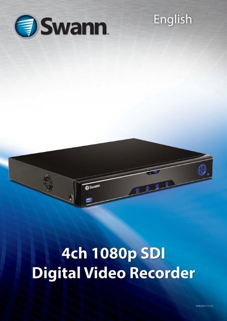
4ch 1080p SDI<br />
English<br />
Digital Video Recorder<br />
M48200H121212E<br />
1
Introduction<br />
2<br />
English<br />
FCC Verification<br />
Before You Begin<br />
NOTE: This equipment has been tested and found to comply with the limits for Class B digital device, pursuant to part 15 of the<br />
FCC Rules. These limits are designed to provide reasonable protection against harmful interference in a residential installation.<br />
This equipment generates, uses and can radiate radio frequency energy and, if not installed and used in accordance with<br />
the instructions, may cause harmful interference to radio or television reception, which can be determined by turning the<br />
equipment off and on, the user is encouraged to try to correct the interference by one or more of the following measures:<br />
• Reorient or relocate the receiving antenna<br />
• Increase the separation between the equipment and the receiver<br />
• Connect the equipment into an outlet on a circuit different from that to which the receiver is connected<br />
• Consult the dealer or an experienced radio/TV technician for help<br />
These devices comply with part 15 of the FCC Rules. Operation is subject to the following two conditions:<br />
• These devices may not cause harmful interference, and<br />
• These devices must accept any interference received, including interference that may cause undesired operation.<br />
IMPORTANT NOTE:<br />
All jurisdictions have specific laws and regulations relating to the use of cameras. Before using any camera for any purpose, it<br />
is the buyer’s responsibility to be aware of all applicable laws and regulations that prohibit or limit the use of cameras and to<br />
comply with the applicable laws and regulations.<br />
FCC Regulation (for USA): Prohibition against eavesdropping<br />
Except for the operations of law enforcement officers conducted under lawful authority, no person shall use, either directly<br />
or indirectly, a device operated pursuant to the provisions of this Part for the purpose of overhearing or recording the private<br />
conversations of others unless such use is authorized by all of the parties engaging in the conversation.<br />
WARNING<br />
Modifications not approved by the party responsible for compliance could void user’s authority to operate the equipment.<br />
IMPORTANT SAFETY INSTRUCTIONS<br />
• Make sure product is fixed correctly and stable if fastened in place<br />
• Do not operate if wires and terminals are exposed<br />
• Do not cover vents on the side or back of the DVR and allow adequate space for ventilation<br />
DEFAULT PASSWORD INFORMATION<br />
To ensure your privacy, this DVR supports password protection.<br />
The default, all-access username is “admin”. If the DVR asks you to log in before you’ve set a password, enter admin as your<br />
username and leave the password blank. This will give you access to all areas of the DVR.<br />
The password function is disabled by default. However, if you’re asked for a password, the default is “12345”.<br />
To ensure your ongoing privacy, we strongly recommend setting a password as soon as possible. Choose something that<br />
you’ll remember, but that others would be unlikely to guess.<br />
If you do manage to lock yourself out of the DVR, you’ll need to contact us at the Swann Technical Support Telephone Helpdesk<br />
- the number is on the back cover.
English<br />
Introduction<br />
Before You Begin 2<br />
Contents 3<br />
Introduction 4<br />
Connecting the DVR<br />
Installation Guidelines 5<br />
Front Panel of the DVR 5<br />
The Rear Panel of the DVR 6<br />
Connection Diagram 7<br />
Connecting Additional Devices 8<br />
The Alarm & Sensor I/O Block 9<br />
Basic Setup<br />
SDI: How it compares to traditional CCTV 10<br />
Basic DVR Operation 10<br />
Basic Setup: General 11<br />
Basic Setup: HDD & Networking 12<br />
Basic Setup: DDNS & Email 13<br />
Basic Setup: NTP & DST 14<br />
Basic Setup: Account Configuration & Completion 15<br />
Basic Setup: Installing MyDVR on PC 16<br />
MyDVR: Logging In 17<br />
MyDVR: Interface 18<br />
MyDVR: Local Configuration 19<br />
MyDVR: Configuration Overview 20<br />
Remote Access From a Mobile Device 24<br />
Advanced Configuration<br />
Operating the DVR Locally 25<br />
Menu Layout 26<br />
Advanced Configuration 27<br />
Display: Camera 28<br />
Display: Output 29<br />
Recording: Encode 30<br />
Recording: Option 31<br />
Recording: Schedule 32<br />
Search: Playback 33<br />
Contents<br />
Search: Backup 34<br />
Search: Event 35<br />
Search: Log Search 35<br />
The Playback Interface 36<br />
Network: General 37<br />
Network: Advanced 38<br />
Network: Advanced: DDNS 39<br />
Network: Advanced: NTP 39<br />
Network: Advanced: IP Filter 40<br />
Network: Network Status 40<br />
Network: Advanced: Email Settings 41<br />
Alarm: Motion 42<br />
Alarm: Motion Detection Configuration 43<br />
Alarm: Motion Detection Notes 44<br />
Alarm: Motion Detection - Action 45<br />
Alarm: Video Loss 45<br />
Alarm: Sensor 46<br />
Alarm: Alarm Output 47<br />
Alarm: Exception 48<br />
Device: HDD 49<br />
Device: S.M.A.R.T. 49<br />
Device: PTZ 50<br />
System: General 52<br />
System: User 53<br />
System: System Information 54<br />
System: Device State 54<br />
System: Maintenance 55<br />
Reference<br />
Troubleshooting 56<br />
Addendum: Third Party Hardware 57<br />
Technical Specifications 58<br />
Warranty Information 59<br />
Helpdesk / Technical Support Details 60<br />
3<br />
Introduction
Introduction<br />
4<br />
English<br />
Congratuations on your purchase of this Swann DVR. You’ve<br />
made a fine choice for keeping a watchful eye over your home<br />
or business. Let’s take a moment to talk about some of the<br />
features this DVR offers, and how to get the most out of them.<br />
Oh my, this is a big <strong>manual</strong>. How long will this take?<br />
Yes, but you won’t have to read all of it - you should be up and<br />
running by page 25!<br />
It can take a few hours to connect everything and run through<br />
the setup procedure.<br />
The latter half of this <strong>manual</strong> is for advanced users only - the<br />
DVR is seriously configurable - the out-of-the-box settings do<br />
a great job in 90% of situations, but some users will want to<br />
get into the nitty-gritty detail, so that information is presented<br />
for those who need it.<br />
The Basic Setup<br />
The default settings of the DVR will cover most basic<br />
installation requirements of the DVR.<br />
To get the most out of your hard drive, we’ve configured the<br />
DVR to record only when it detects motion - that way, you<br />
won’t fill the hard drive with video of nothing happening.<br />
Before installing anything, connect the DVR and cameras<br />
and test your system.<br />
We ensure everything is working properly when we ship<br />
them out, but sometimes things can be damaged in<br />
transport, and occasionally components can fail. Better to<br />
find out now, before everything is fixed in place!<br />
Introduction<br />
Getting the DVR Setup<br />
There are three stages to getting your DVR set up. If you want<br />
to use the default settings, you’ll only need to complete steps<br />
one and two.<br />
Stage 1. Connecting the DVR (page 5 to page 9)<br />
This sections details what you can connect to the different<br />
inputs/outputs of the DVR.<br />
Everyone’s setup will vary a little bit - it depends what cameras<br />
came with the DVR (if any) and what device(s) you’ve already<br />
got.<br />
Stage 2. Basic DVR Setup<br />
The DVR needs a few things to be set properly before it can do<br />
its thing. Follow the instructions from page page 11 to page<br />
24 to get everything working.<br />
3. Optional: Advanced DVR Configuration<br />
The latter part of this <strong>manual</strong> covers advanced DVR operations.<br />
This DVR comes with all the professional-grade capabilities<br />
you’d expect from a quality Swann product, but many<br />
advanced capabilities require detailed setup to function<br />
correctly.<br />
If you’re not an advanced user, don’t worry. The out-of-the-box<br />
settings really do work well, and we’d only suggest changing<br />
them if you’ve got a really specific plan in mind.<br />
You’ll need to read a page or two of this section if:<br />
• you’ve got a PTZ capable camera - see page 50.<br />
• you’re connecting external sensors (page 46).<br />
• you want to alter the motion detection sensitivity or the<br />
areas it applies to (page 42).<br />
What is “SDI”, and why is it so good?<br />
A Serial Digital Interface is another way of transmitting images from a camera to the DVR, offering up to<br />
six times the image quality of composite video.<br />
(Some relevant math, for the curious: (1920 x 1080) / (720 x 480) = 6).<br />
The SDI camera channels on this DVR are capable of recording at 1080p FULL HD in real-time, which is<br />
approximately five to six times the information content of composite video. SDI uses very similar cables to<br />
composite video, but they’re a little bit different. For best results, ensure you use the supplied cables.<br />
For the DVR to work correctly, ensure that:<br />
ONLY Swann SDI cameras are connected to the SDI camera inputs.<br />
Composite Video Cameras are not compatible with this DVR.
English<br />
• Do not expose the DVR to moisture. Water is<br />
the arch-enemy of electrical components and<br />
also poses a high risk of electric shock.<br />
• Avoid dusty locations. Dust has a tendency to<br />
build up inside the DVR case, leading to a high<br />
risk of failure or even fire.<br />
• Only install the DVR in a well ventilated<br />
space. Like all electronics, the circuitry and hard<br />
drive in the DVR produce heat, and this heat<br />
needs a way out.<br />
• Do not open the DVR case except to install/<br />
swap the hard drive inside. There are no user<br />
serviceable parts inside.<br />
• Never open the case whilst the DVR is<br />
plugged in, and never turn the DVR on whilst<br />
the case is open.<br />
1<br />
1) USB 2.0 Port: For connecting the USB mouse, USB external<br />
storage to the DVR for backup, or for applying new firmware.<br />
2) Play/Pause: Opens the playback interface from the live<br />
viewing mode. Pauses playback or resumes playback from<br />
paused.<br />
3) Display: Enters split-screen view, where the screen shows<br />
one or four (2 x 2) video feeds at once.<br />
4) Menu/ESC: Opens the DVR’s menu, or goes back one step<br />
from a submenu.<br />
Installation Guidelines<br />
Front Panel of the DVR<br />
2<br />
8<br />
• Use only the supplied power adapter. Other<br />
adapters may cause damage to the DVR or<br />
cause a fire.<br />
• Do not cut or modify any cable for any reason.<br />
Doing so will void your warranty, as well as pose<br />
a great risk of fire or electrical shock.<br />
• Do not expose the DVR to sudden bumps or<br />
shocks (for example, being dropped). The DVR<br />
is as robust as possible, but many of the internal<br />
components are quite fragile.<br />
• Remember that the DVR is, in all likelihood,<br />
going to be left on 24 hours a day, 7 days<br />
a week. Keep this in mind when choosing a<br />
location for installation.<br />
7<br />
3 4 5<br />
5) Select: As the name suggests, it selects an option or item<br />
from a menu.<br />
6) D-pad: For navigating around menus when you’re not using<br />
the mouse. (Why aren’t you using the mouse? It’s awesome.)<br />
7) Power LED: Will be lit whenever the DVR is supplied power<br />
and turned on.<br />
8) HDD LED: Will flash whenever the DVR is writing to/reading<br />
from the installed hard drive.<br />
6<br />
5<br />
Connecting the DVR
Connecting the DVR<br />
6<br />
English<br />
1) SDI Inputs 1 - 4: These are the high-definition video inputs<br />
and are where you should connect your 1080p SDI cameras.<br />
These connection use a similar BNC connector to a composite<br />
video channel found on other DVR models, however the<br />
cameras (and some cables) are not interchangable.<br />
For the best results , don’t use existing composite video cable<br />
but rather connect your SDI camera(s) with the supplied<br />
cables marked for use with SDI.<br />
2) Audio Inputs: These will accept a standard line-level signal<br />
(
English<br />
Connect the SDI outputs from<br />
your cameras into the marked SDI<br />
inputs on the rear of the DVR.<br />
Connection Diagram<br />
Connect an ethernet<br />
cable from the LAN<br />
port on the DVR to<br />
a spare port on your<br />
router.<br />
If you’ve got a<br />
monitor with<br />
VGA but not<br />
HDMI, connect<br />
it to the VGA<br />
output on the<br />
DVR.<br />
Connect your cameras to<br />
power, using the a powersplitter<br />
(if included).<br />
Connect the DC12V<br />
Output from the<br />
power supply to<br />
the power input.<br />
Connect the power<br />
adapter(s) to a wall outlet.<br />
If you’ve got a TV or monitor with<br />
HDMI in, connect to the HDMI port<br />
on the DVR.<br />
7<br />
Connecting the DVR
Connecting the DVR<br />
8<br />
English<br />
An external<br />
hard drive with<br />
an eSATA port can<br />
be connected to the<br />
eSATA port on the DVR,<br />
and can be utilized in the<br />
same manner as the internal<br />
HDD.<br />
Connecting Additional Devices<br />
The Audio Out<br />
port can be used<br />
to connect a<br />
stereo, speakers,<br />
headphones or<br />
other external sound<br />
device.<br />
The combination USB/eSATA1 Port is used<br />
for backing up footage. You can connect:<br />
- A USB Flash Drive<br />
- A USB Hard Drive<br />
- An eSATA Hard Drive<br />
Note: If using USB storage media, USB 2.0 (or<br />
faster) devices are recommended.<br />
The Audio In ports can be<br />
used to connect audio devices<br />
to the DVR. Obviously, your<br />
microphone probably won’t look<br />
like that one - they’re often built<br />
into cameras.<br />
The PTZ port (RS485)<br />
can be used to connect<br />
compatible PTZ<br />
devices, such as this<br />
Swann PTZ SDI dome.<br />
Connect the mouse to the front USB 2.0 Port.<br />
This port can also be used to connect USB devices to<br />
backup to, but you’ll need to unplug the mouse to do it.
English<br />
The Alarm Ports on the DVR sport a removable terminal block.<br />
The terminal block is used to facilitate easy connection and<br />
disconnection of so many wires, rather than having to unscrew<br />
each one individually if you want to move the DVR or access<br />
the rear panel.<br />
Alarm In 1 - 4: Connect the output from external sensors<br />
here. Only one of the two outputs should be connected here,<br />
the other should be connected to a 12V terminal and/or the<br />
Ground terminal, depending on the requirements of the<br />
sensor (consult the documentation for the sensor).<br />
The Alarm In number does not directly correspond with a<br />
channel number - these can be set later (see “Alarm: Sensor”<br />
on page 46 in Advanced Configuration for details).<br />
The Alarm & Sensor I/O Block<br />
The Alarm I/O Block<br />
12V: Active DC power output. Connect any sensor device<br />
inputs which require 12V DC here. The Alarm IN connections<br />
share common +12V DC connections.<br />
GND: The ground connections. The Alarm IN and Alarm OUT<br />
connections share a common ground.<br />
Alarm Out: The outputs for connecting an external alarm<br />
device, such as a siren or security lights, to the DVR.<br />
N1, C1: The outputs for Alarm Out 1. Check your alarm device’s<br />
documentation to see which ports should be connected.<br />
9<br />
Connecting the DVR
Basic Setup<br />
10<br />
English<br />
SDI: How it compares to traditional CCTV<br />
Swann DVRs can features two different kinds of input channels,<br />
the high definition SDI channels, and the standard definition<br />
composite video channels. This DVR is entirely SDI, so only<br />
supports SDI cameras. For best results we recommend using<br />
Swann SDI cameras.<br />
SDI<br />
SDI technology allows 1080p Full HD images to be transmitted<br />
via similar cables to traditional, analogue video. By encoding<br />
the information digitally, you can transmit up to six times the<br />
resolution of traditional CCTV cameras.<br />
This means that:<br />
• Your images will be far more detailed than traditional<br />
CCTV camera footage.<br />
• You can use wider angle cameras to cover more area at<br />
the same level of detail as traditional cameras<br />
• Your DVR is going to require more hard drive space to<br />
record images from your cameras than traditional CCTV<br />
cameras (all that quality has to be stored somewhere!)<br />
The USB Mouse (Recommended)<br />
The easiest way to operate the DVR is to use the included USB<br />
optical mouse - we put together the look and feel of the menu<br />
system specifically for mouse-friendly navigation.<br />
The controls are pretty easy to remember - heck, there are only<br />
two buttons. It couldn’t be simpler.<br />
Left click:<br />
• Selects an item or confirms a choice.<br />
Right click:<br />
• Opens the menu bar from the live viewing screen.<br />
• Returns one “step” from a submenu.<br />
• Opens a context menu in some settings screens.<br />
The Scroll Wheel:<br />
• Can be used to adjust the values of sliders and scales<br />
when highlighted by the mouse.<br />
Of course, you don’t have to use the mouse.<br />
Basic DVR Operation<br />
To maximize the (many) advantages of SDI while minimizing<br />
(few) drawbacks:<br />
• As much as possible, make use of Motion Detection and/<br />
or Alarm-based recording as your primary recording<br />
mode(s). This will help save hard drive space as the DVR<br />
will not be filling it’s internal storage with images of<br />
nothing happening.<br />
• It’s more important that cameras with adjustable lenses<br />
(such as adjustable zoom or focus, or both) must have<br />
these set as accurately as possible.<br />
The Front Panel<br />
The buttons on the front panel are adequate for operating the<br />
DVR, but they’re hardly ideal for ongoing use.<br />
Between Menu, Select and the D-pad (directional pad) you can<br />
navigate through all the DVR’s menus and configure almost<br />
any setting. It’s a little clunkier than the mouse and it’s not as<br />
quick and easy, but it does save a little space.<br />
Wireless Mice<br />
Many wireless mice are compatible with the DVR. The only<br />
kinds of wireless devices compatible are those that interface<br />
in the same manner as regular wired devices: typically, these<br />
will be mice which come with a dedicated USB receiver which<br />
is pre-paired to the mouse.<br />
Combination wireless receivers (such as those that come with<br />
keyboard/mouse combinations) are usually NOT compatible<br />
with the DVR. We suggest avoiding them.<br />
Note that Bluetooth devices are NOT compatible with the<br />
DVR. Use a wireless mouse that has a dedicated USB receiver.
English<br />
Basic Setup: General<br />
The Setup Wizard will run automatically the first time you start the DVR.<br />
The wizard will guide you through all the settings you need to get your DVR up and working, specifically:<br />
• Choosing your Language<br />
• Setting Video Input and Output Formats and Resolution<br />
• Setting the Date, Time and your Time Zone<br />
• Initializing and/or Formatting your Hard Drive<br />
• Configuring the DVR to operate on your Network<br />
• Setting up a Dynamic DNS for remote access<br />
• Synchronizing the DVR’s time with an online server<br />
• Choosing the settings for Daylight Savings Time (DST)<br />
• Creating Username(s) and Password(s)<br />
Note: There are still a few things you’ll really want to setup after you’ve finished with the wizard - the theory is that, once you’ve got<br />
through the set up wizard, you can install the MyDVR software on a PC connected to the same network and configure the remaining<br />
options via your computer.<br />
General Configuration<br />
Language: Choose the language you’d<br />
like the menu system to be displayed in.<br />
Video Standard: Choose between NTSC<br />
(for the USA, Canada, Mexico, Japan,<br />
Korea and some other regions) or PAL<br />
(UK, Europe, Australia and some other<br />
areas). If this is set incorrectly, images<br />
captured under certain conditions (such<br />
as under fluorescent lights or near a<br />
television) will appear to flicker.<br />
Resolution: How many pixels the DVR<br />
will output. Typically, you’ll want to set<br />
this to be equal to the native resolution<br />
of your monitor/television (check the<br />
manufacturer’s documentation). If<br />
your monitor’s native resolution isn’t<br />
an option, then you’ll want to use the<br />
highest resolution possible without<br />
exceeding the maximum resolution of<br />
your monitor.<br />
Time Zone: Choose the time zone you’re in. It’s really important to select the right time zone if you’re using NTP (Network Time<br />
Protocol).<br />
Some common time zones: In the USA, EST (Eastern Standard Time) is GMT -5:00, where PST (Pacific Standard Time) is GMT -8:00.<br />
The UK is GMT +0:00, and the East Coast of Australia is GMT +10:00.<br />
Menu Date Format: How you’d like the date to be displayed. Choose whichever format is standard in your region.<br />
If you need to change any of these settings later, you can find these options:<br />
Main Menu -> System -> General<br />
11<br />
Basic Setup
Basic Setup<br />
12<br />
English<br />
HDD<br />
Basic Setup: HDD & Networking<br />
Init.: Initializes the hard drive. You’ll<br />
only need to do this for drives once,<br />
assuming that it’s not already initialized.<br />
If the Mount column reads “No” then<br />
choose Init. to initialize the drive.<br />
Label: A quick way of differentiating<br />
between hard drives. For the first setup,<br />
there will usually only be one hard<br />
drive - you can always add and initialize<br />
another hard drive later (either internal<br />
or connected via eSATA).<br />
Capacity: The total amount of space<br />
on the hard drive. This will typically be<br />
slightly less than the rated capacity of<br />
the hard drive as a fraction of the space<br />
is required by the file allocation table<br />
(FAT).<br />
Format: Whether the hard drive has been formatted to operate with the DVR. When the hard drive is formatted appropriately,<br />
this will simply read “yes”. If it says anything else, such as an ominous “no”, then select the disk and choose Format.<br />
Mount: Whether the drive has been initialized and is detected by the DVR. If the drive isn’t mounted then it needs to be<br />
initialized (see above).<br />
Free Space: The amount of available space on the hard drive.<br />
Network Access<br />
We’re not going to pretend this isn’t the<br />
most complex aspect of configuring the<br />
DVR, but if your router supports DHCP<br />
and UPnP, then there’s nothing to do<br />
here.<br />
Recommended:<br />
Don’t change anything.<br />
Ensure that the Network Access is set to<br />
DHCP and that UPnP is enabled on your<br />
router - it should just work.<br />
If your router doesn’t support DHCP:<br />
Then you’ll need to <strong>manual</strong>ly assign the<br />
address of the DVR. If you’ve already<br />
setup your network, we assume you<br />
know what you’re doing. See “Addendum:<br />
Third Party Hardware” on page 57 for<br />
more information.<br />
If your router supports DHCP but not UPnP: For local access (i.e. a PC connected to the same network) just set the Network<br />
Access to DHCP. For remote access (i.e. a device connected via the Internet), you’ll need to <strong>manual</strong>ly forward ports on your router.<br />
See “Addendum: Third Party Hardware” on page 57 for more information.<br />
If you don’t know how to <strong>manual</strong>ly address devices and don’t have access to someone who does, you may want to consider<br />
upgrading your router - we think that DHCP and UPnP are neat features that are well worth having.<br />
There’s heaps more information on IP Addresses, DHCP, UPnP and all manner of remote access information later in this booklet.<br />
In addition to “Addendum: Third Party Hardware” on page 57, have a look at “Network: General” on page 37 and have a word<br />
with whoever set up your network - they might be able to help you.
English<br />
Basic Setup: DDNS & Email<br />
DDNS<br />
A Dynamic DNS is a service which will let<br />
you assign an address to your DVR so you<br />
can access it via the Internet.<br />
There’s more information about DDNS,<br />
how to configure it and what it means<br />
for you when remotely accessing the<br />
DVR later in this <strong>manual</strong>. Have a look at<br />
“Network: Advanced: DDNS” on page 39<br />
for more.<br />
DDNS Type: The DDNS server you’re<br />
using. We recommend SwannDVR - you<br />
can sign up for your free account at www.<br />
swanndvr.net.<br />
Device Domain Name: The domain name<br />
you chose when signing up for your DDNS<br />
account.<br />
User Name: The username you selected when you signed up for your DDNS account. If you’re using SwannDVR and followed<br />
the suggested username guidelines, this will be your email address.<br />
Password: Enter the password you used when you signed up for your DDNS account.<br />
Confirm Password: Re-enter the password to confirm.<br />
Test: To check if the DDNS is working, click the Test button. After a short delay, a message will be displayed on-screen, informing<br />
you whether the update was successful or not.<br />
If the test is unsuccessful, a message will appear onscreen informing you that the “Update was Unsuccessful”. This could mean<br />
there’s a problem with your network setup, or there’s a problem with the DDNS Account Name and Password you’re using.<br />
Before DDNS will work, you’ll need to register an account with the DDNS provider of your choice. We recommend SwannDVR, as this<br />
is a free service which we support directly. Boot up your computer and sign up at www.swanndvr.com.<br />
Email<br />
If you want the DVR to send email alerts as alarm events are detected, then you’ll need to configure an outgoing email server for<br />
the DVR to use, and choose an email address for it to send to.<br />
We recommend creating an account with Gmail (www.gmail.com) specifically for the DVR. These instructions assume you’re<br />
using a GMail account. If you’re using a different email, see “Network: Advanced: Email Settings” on page 41 for details.<br />
Enable SSL or TLS: Enable.<br />
SMTP Server: Choose smtp.gmail.com<br />
SMTP Port: 465 (this value will self-populate)<br />
Sender Address: your_email@gmail.com<br />
Sender Password: The password you<br />
chose for the GMail account.<br />
Recepient Address 1, 2, 3: Choose up<br />
to three email addresses for the DVR to<br />
send mail to.<br />
Attach Picture: When selected, the DVR<br />
will attach a still image to better illustrate<br />
what has caused the alarm/alert state.<br />
Interval: The minimum amount of time<br />
that must elapse after the DVR sends<br />
an email alert before it can be triggered<br />
again.<br />
Other: Allows for custom definintion of an outgoing email server. See “Network: Advanced: Email Settings” on page 41if you want<br />
to use an email server other than Gmail. For advanced users ONLY.<br />
13<br />
Basic Setup
Basic Setup<br />
14<br />
English<br />
NTP<br />
Basic Setup: NTP & DST<br />
NTP stands for “Network Time Protocol”.<br />
It’s a way for the DVR to automatically<br />
update its internal clock and ensure it’s<br />
always in sync. There’s no requirement<br />
to use NTP, but it’s easy to setup and<br />
free to use, so there’s really no reason<br />
not to.<br />
NTP Server: The server you’d like to use<br />
for NTP. They’re all quite comparable<br />
in terms of reliability and accuracy, so<br />
unless you’ve got some kind of master<br />
plan for world domination (which is<br />
affected by the time, for some reason)<br />
then the default (pool.ntp.org) works<br />
fine.<br />
NTP Port: The default is 123. You<br />
should only change this if you’re using<br />
a different NTP server, and you know<br />
they use a different port. If you’re using<br />
pool.ntp.org, ensure the port is 123.<br />
Sync: Triggers the DVR to automatically synchronize its internal clock with the time server immediately. If your DVR is connected<br />
to the Internet and the network is correctly configured, this will update almost instantly.<br />
System Time: The DVR’s current clock reading.<br />
DST Configuration<br />
You can configure the DVR to<br />
automatically update it’s internal clock<br />
when daylight saving starts and ends.<br />
Note that using DST and NTP<br />
simultaneously can cause problems,<br />
depending on your NTP server and how<br />
DST works in your locale.<br />
Enable: Whether the DVR will<br />
automatically adjust the time for DST or<br />
not.<br />
Offset: The amount by which the time<br />
changes during DST. For the vast majority<br />
of locations, the offset is one hour, but<br />
exceptions to this rule exist.<br />
Start Time / End Time: When DST begins<br />
and ends in your locale.
English<br />
Basic Setup: Account Configuration & Completion<br />
Account Configuration<br />
User Name: The name you’d like to<br />
use for the account. An account can<br />
be called anything you like (up to 16<br />
characters in length) except the default<br />
Admin account, which is always called<br />
“Admin”. We suggest using this as the<br />
default all-access account for the DVR.<br />
Password: The password you’d like<br />
to be associated with the selected<br />
account. A password can be between<br />
1 and 8 characters in length, and<br />
consists of numbers only (no letters or<br />
symbols).<br />
Confirm Password: Re-enter the<br />
password to ensure accuracy.<br />
Level: The level of access that the selected account will have. There are three levels of access: Guest, User or Admin.<br />
Guests: Can view live images from the cameras, but cannot access recorded footage, nor can they alter any settings.<br />
User: The most customizable level of access to the DVR. You’ll be able to set a User account to have as little access as a Guest<br />
account, or nearly as much power as an Admin account. User accounts will probably make up the majority of accounts registered<br />
to a DVR if there are multiple users requiring varying levels of access.<br />
Finishing the Setup Wizard<br />
When you choose Finish, the DVR will update and save your settings. It may reboot while doing so.<br />
If you don’t want the Setup Wizard to be dispalyed upon startup in the future, uncheck the “Run Wizard at Startup” checkbox.<br />
Display wizard when booting up (checkbox): While this is highlighted, the DVR will automatically run the configuration<br />
wizard when booted up. Simply click this box to de-select it, and the wizard won’t run automatically in future. You can run the<br />
wizard at any time by clicking the icon on the DVR menu tray.<br />
15<br />
Basic Setup
Basic Setup<br />
16<br />
English<br />
Your DVR comes with powerful remote access and interface<br />
software, called MyDVR. You can setup and configure almost<br />
all aspects of the DVR from the MyDVR interface.<br />
The MyDVR software will allow you to:<br />
• view images from your DVR in real-time,<br />
• playback recorded footage,<br />
• copy footage to your local PC and<br />
• adjust settings and configure the DVR.<br />
In fact, the MyDVR software is so powerful, you don’t even<br />
need to connect a monitor to the DVR if there’s a computer on<br />
the local network that you’re running MyDVR on.<br />
For quick and easy configuration of the DVR’s settings,<br />
recording quality and schedule, we suggest using the<br />
remote interface in MyDVR.<br />
How to install MyDVR:<br />
• Insert the included CD into your computer.<br />
• Locate the file called MyDVR Windows vxxxx.exe and run<br />
this fileYou may be asked by UAC (User Account Control)<br />
to allow MyDVR to “make changes” to your system. Select<br />
Allow or Continue.<br />
• You’ll see an installation wizard. Simply follow the prompts<br />
to install the software.<br />
• Once the MyDVR software has been installed, it should<br />
automatically detect your DVR on your network.<br />
Minimum PC Requirements:<br />
2.0GHz or faster CPU (Dual-core recommended)<br />
1GB or more RAM (2GB recommended)<br />
10/100Mbps Network (1000Mbps recommended)<br />
Internet connection (512kbps+ recommended)<br />
1024x768 resolution (1280x720 recommended)<br />
Basic Setup: Installing MyDVR on PC<br />
Supported Operating Systems<br />
Microsoft Windows XP, Microsoft Windows Vista, Microsoft<br />
Windows 7 and Microsoft Windows 8<br />
NOTE: Windows XP, Windows Vista, Windows 7 and Windows 8<br />
are registered trademarks of Microsoft Corporation.<br />
Got a Mac?<br />
Check out<br />
www.swann.com/mydvrmac<br />
for the latest Mac-based remote<br />
access software.
English<br />
Before running MyDVR for the first time:<br />
Ensure your DVR is connected to a network and (if accessing<br />
via the Internet) you know the Public IP Address of the DVR<br />
or the DDNS address (see “Network: Advanced: DDNS” on<br />
“Network: Advanced: DDNS” on page 39 for more).<br />
That your network is set to DHCP addressing or the DVR<br />
has been configured to use STATIC addressing (see “Network:<br />
General” on page 37).<br />
That UPnP is enabled on your router (see your router’s<br />
documentation to learn more).<br />
If you’re accessing the DVR via a LAN (local network):<br />
• Select LAN under the heading Network Type (unless your<br />
computer has performance issues - then select WAN. See the<br />
note on multiple monitors, below/right).<br />
• Your DVR should automatically appear in the list of<br />
compatible devices near the top of the window.<br />
• If your DVR does not appear, choose Scan Device in LAN.<br />
If this doesn’t work, then it indicates some kind of local<br />
network fault.<br />
• Select your DVR from the list - it will probably be the only<br />
thing there, unless you’ve got another Swann DVR.<br />
MyDVR: Logging In<br />
Default Password Information<br />
If you’re logging in to the DVR for the<br />
first time via a local network, then use<br />
the following settings:<br />
• IP: This field will self-populate when<br />
you select a DVR from the list.<br />
• Server Port: The default is 9000.<br />
MyDVR will automatically detect the<br />
server port of the DVR.<br />
• Username: To get full control of the<br />
DVR, use the default administrator<br />
username: admin. You can create<br />
other accounts, but the default is<br />
always called admin.<br />
• Password: Enter the admin account<br />
password here. If you haven’t set a<br />
password yet, then leave this field<br />
blank (and we suggest that you set a<br />
password as soon as possible).<br />
If you’re accessing the DVR via the Internet:<br />
• Select WAN under the heading Network Type.<br />
• If you’re using a Fixed Public IP address, choose IP<br />
Address under Register Mode, and enter the IP address<br />
into the space marked IP.<br />
• If you’re using a DDNS hostname, choose Domain Name<br />
under Register Mode, and enter the DDNS domain name<br />
into the field labeled Domain.<br />
• If you’re using the SwannDVR DDNS service, your address<br />
will be: yourDDNSname.swanndvr.net<br />
• Enter the Server Port for the DVR. The default is 9000.<br />
The DVR won’t be able to automatically detect this over the<br />
Internet - you’ll need to remember it if you’ve changed it!<br />
• Enter your Username and Password.<br />
• Choose Login.<br />
Note: Multiple Monitors<br />
Windows does not support hardware video acceleration when<br />
using multiple monitors. On some systems, this can cause<br />
significantly reduced performance when running in LAN mode.<br />
If you experience slow playback or the video is not being displayed<br />
at all, disable all monitors but your primary one. Selecting WAN<br />
mode (even over a local network) can also improve performance.<br />
To ensure your privacy, this DVR supports password protection.<br />
The default, all-access username is “admin”. If the DVR asks you to log in before you’ve set a password, enter<br />
admin as your username and leave the password blank. This will give you access to all areas of the DVR.<br />
The password function is disabled by default. However, if you’re asked for a password, the default is “12345”.<br />
To ensure your ongoing privacy, we strongly recommend setting a password as soon as possible. Choose<br />
something that you’ll remember, but that others would be unlikely to guess.<br />
If you do manage to lock yourself out of the DVR, you’ll need to contact us at the Swann Technical Support<br />
Telephone Helpdesk - the number is on the back cover.<br />
17<br />
Basic Setup
Basic Setup<br />
18<br />
English<br />
HALLWAY<br />
Playback and<br />
Backup Links<br />
20/12/2012 13:39:24 MON<br />
Preview / Playback / Setup<br />
Channel List<br />
MyDVR: Interface<br />
20/12/2012 13:39:24 MON<br />
20/12/2012 13:39:24 MON 20/12/2012 13:39:24 MON<br />
LOUNGE ROOM GARDEN CAMERA<br />
Preview: The default splash live-view screen of MyDVR.<br />
Main Viewing STUDY<br />
Area<br />
The screen layout emulates the multi-channel live view<br />
screen of the DVR, showing you images coming directly from<br />
your cameras in near real-time (some delay is caused by the<br />
network/Internet connection you’re using to access the DVR).<br />
You can select a single camera, or multi-channel viewing by<br />
using the Viewing Mode buttons in the lower right corner.<br />
Playback: Opens the Playback interface, which operates in<br />
much the same way as the playback interface on the DVR itself.<br />
Setup (Configuration): Allows access to both the Local<br />
Config screen and Remote Configuration menus.<br />
Local Config: Defines how MyDVR will manage and save<br />
footage and still images to your local PC.<br />
Remote Config: Allows access to the DVR’s settings. The<br />
configurable options are very similar to those you’ll find in the<br />
DVR menus.<br />
Main Viewing Area: Where images from your camera will<br />
be shown. Select Preview to return to this view from the<br />
Playback interface or the Config menus.<br />
Playback / Backup Links: Quick access to playback and<br />
backup.<br />
PTZ Controls: For controlling PTZ devices. They operate in the<br />
same way as those you’ll find on the DVR itself.<br />
Need more details?<br />
PTZ Controls &<br />
Image Controls<br />
Viewing Modes &<br />
Volume Control<br />
Image Controls: You can alter the brightness, contrast,<br />
saturation and hue of your images here. They operate in the<br />
same way as those in the DVR’s menu (see “Display: Camera”<br />
on page 28 for more information).<br />
Viewing Modes: Choose between single camera viewing,<br />
four channels at once (2 x 2).<br />
Volume Control: Alters how loud the audio output from the<br />
DVR will be. Remember that the final output volume will also<br />
be affected by the master volume control of your operating<br />
system, as well as the levels set on speakers or amplifiers<br />
connected to your system.<br />
CPU Loading: How hard your computer is working to decode<br />
and display images as they arrive from the DVR. If this is<br />
consistently high, you can try:<br />
• disabling multiple monitor setups. The MyDVR application<br />
doesn’t support hardware acceleration across multiple<br />
monitors. Disabling all but your primary monitor will<br />
greatly increase performance.<br />
• reducing the quality of the video. Select WAN from the<br />
login screen instead of LAN.<br />
• reduce the number of video feeds being displayed. Select<br />
a channel and click Stop to disable the monitoring.<br />
• switch to single channel view.<br />
The overview of the DVR settings presented over the next few pages is just that - an overview.<br />
The full explanation of the DVR’s menu system and configuration options are listed in detail from<br />
page 25 onwards. The DVR’s menu system is functionally very similar to the MyDVR software<br />
interface, and you’ll find more detailed information about all menu options and settings there.<br />
The relevant page for additional information is listed next to each menu screen.
English<br />
The local configuration screen is where you can customise<br />
how MyDVR will store and process footage on the local PC<br />
when you download it from the DVR.<br />
Record Path: Where MyDVR will save recordings if you select<br />
Record from the Preview screen.<br />
Download Path: Where MyDVR will save footage that you’ve<br />
downloaded from the DVR.<br />
Snapshot Path: Where MyDVR will save still images captured<br />
using the snapshot function.<br />
Convert to AVI: When selected, MyDVR will use your PC to<br />
transcode footage from the DVR’s native format (H.264) into a<br />
format that your computer (indeed, almost any computer) will<br />
be able to playback without special software.<br />
MyDVR: Local Configuration<br />
Playback Problems?<br />
About transcoding to AVI:<br />
Don’t be put off by the complex word - transcoding is just a<br />
shortening of “translating code”.<br />
Transcoding, while a straight-forward process, is very<br />
processor intensive. You may notice significant slow-down<br />
on your computer while the transcoding takes place. For<br />
best results, try not to over-burden your computer - just let it<br />
transcode the footage in peace.<br />
Auto-Login: When selected, MyDVR will automatically<br />
login and open the Preview screen for the DVR it is currently<br />
connected to. Simply un-check Auto-Login if you don’t want<br />
MyDVR to do this anymore, or you want to change the default<br />
device (you’ll just need to go through the <strong>manual</strong> login<br />
procedure once for the device you want).<br />
Some media players have trouble playing back the transcoded AVI files from the MyDVR software.<br />
We recommend using VLC media player, which has no problems with the DVR’s AVI files.<br />
You can get it for free from www.videolan.org/vlc.<br />
Note: Very few (if any) media players will be able to play the un-modified H.264 video streams that are the DVR’s<br />
native format. The H.264 streams are raw video data with no “container” (AVI is a “container”). It’s a little like trying<br />
to read a book with no punctuation or capital letters or spaces - the “transcoding” process puts in the spaces and<br />
the full stops and makes it possible to be “read” by someone other than the author.<br />
19<br />
Basic Setup
Basic Setup<br />
20<br />
English<br />
MyDVR: Configuration Overview<br />
Display: Channel Settings (see page 28)<br />
Channel Name (Check Box): Whether the channel’s name will<br />
be displayed on screen or not.<br />
Channel Name: The title you’d like to give that camera.<br />
Record Data: Whether the overlays (Channel Name, Date and<br />
so on) will be recorded onto the video with your images.<br />
Mask (Check Box): Turns the masking function on or off.<br />
Mask (Setup): Creates a black privacy overlay which masks part<br />
of your images. Will affect recordings.<br />
Recording: General (page 30 for more)<br />
Encoding Parameter: Choose from the main-stream or substream<br />
to configure.<br />
Main Stream: The way the DVR will internally process and<br />
record video.<br />
Sub Stream: The way the DVR will encode and send video to a<br />
remote device (such as the PC you’re using to access the DVR).<br />
Record Audio (Check Box): Turn the audio recording function<br />
on or off. Note: Record Audio must be specifically enabled for<br />
the SubStream if you require audio via a remote connection.<br />
Resolution: How many pixels (little dots) make up your image.<br />
SDI uses 1920 x 1080 (Full HD) pixels from each camera.<br />
Frame Rate: How many images per second the DVR will capture.<br />
“Realtime” is 30fps (NTSC) or 25fps (PAL).<br />
BitRate Limit: The maximum size that your video files will be.<br />
The higher this is set, the better recordings will look - however,<br />
they’ll also fill the hard drive faster.<br />
Recording: Advanced Config (see page 31)<br />
Overwrite: Whether the DVR will erase old recordings to make<br />
room for new ones, or not.<br />
Pre-record: Whether the DVR will cache and save footage that<br />
occurs immediately before an alarm/motion event.<br />
Delay: How long after an alarm event or motion the DVR will<br />
continue to record for.<br />
Pack Duration: The amount of video that will be stored as a<br />
single “pack”. Unless you have very specific requirements, leave<br />
this at the default value.<br />
Recording: Schedule (see page 32)<br />
The schedule presented on-screen applies to one channel on<br />
one specific day of the week only.<br />
Use the Copy To functions to quickly assign identical schedule<br />
layouts to multiple days/channels at once.<br />
Be careful when programming your schedule. It’s one of the most<br />
important aspects of setting up your DVR, and if it’s wrong in any<br />
way, it could lead to complications later.<br />
Note: Do NOT select Normal and Motion/Alarm-based<br />
recording at the same time on the same channel - this can<br />
cause conflicts in the way that the DVR interprets footage and<br />
event information.
English<br />
Network: General (see page 37 for more)<br />
Be careful adjusting settings here - if the DVR can’t access the<br />
network anymore, you won’t be able to configure it remotely!<br />
Network Access: How your network is addressed - either DHCP<br />
or STATIC IP addressing.<br />
Subnet Mask: A required additional piece of IP addressing<br />
information.<br />
Gateway: The way “out” of your network, to the Internet.<br />
Auto DNS / Static DNS: Whether the DVR will automatically<br />
select a DNS server, or use one you assign.<br />
Preferred / Alternate DNS: The DVR has two DNS servers,<br />
essentially a primary and a backup.<br />
MAC Address: The Media Access Control address. For some<br />
advanced networking, it can help to know this value.<br />
Network: Advanced Config (see page 38)<br />
DDNS Setup: Opens the DDNS setup window (below).<br />
NTP Setup: Opens the Network Time Protocol setup window<br />
(see below).<br />
Email Setting: Opens the Email Setup window (see below).<br />
Server Port: One of the two ports the DVR needs to<br />
communicate over your network. Ensure nothing else uses this<br />
port. The default value is 9000. This is the port number you’ll<br />
use when logging in over the Internet from the MyDVR software<br />
or remote access from a mobile device.<br />
HTTP Port: The second of two ports the DVR needs to<br />
communicate over your network. Ensure nothing else uses this<br />
port. The default value is 85.<br />
• NTP Setup (see page 39)<br />
NTP Domain or IP Address: The server you intend to use to<br />
access the current date and time. The default is pool.ntp.org.<br />
NTP Port: The port that the NTP server uses. The default for<br />
pool.ntp.org is 123.<br />
• Email Setting (see page 41)<br />
Operates in the same way as the email setup menu in the DVR<br />
menu. Rather than attempt to summarize here, it’s easier to<br />
simply turn to page 41 to learn more.<br />
• DDNS Setup (see page 39)<br />
Where you can configure a Dynamic DNS server to track the<br />
“position” of your DVR over the Internet. Check out page 39<br />
for more information on DDNS servers.<br />
We recommend using SWANNDVR as your DNS service.<br />
This is a free service for Swann DVR owners, which we directly<br />
support.<br />
To create an account with SWANNDVR, go to:<br />
http://www.swanndvr.com/<br />
and click the Registration button. Follow the prompts to create<br />
your account.<br />
21<br />
Basic Setup
Basic Setup<br />
22<br />
English<br />
Alarm: Motion Detection (see page 42)<br />
Channel: The channel you’re configuring the motion detection<br />
settings for.<br />
Enable: Whether the motion detection is enabled for the<br />
channel currently selected.<br />
Sensitivity: A sliding scale between 1 and 50. The number refers<br />
to the number of pixels (as a percentage) that have to “change”<br />
between frames - okay, this one is a little more complex than<br />
this summary will allow. Seriously - check out page 42 for a<br />
much more useful explanation of how motion detection works.<br />
Action: What you’d like the DVR to do when it detects motion.<br />
Typically (assuming the schedule is configured to do so) this will<br />
be to record video. It can also be a cue to trigger an email alert,<br />
or to sound the DVR’s internal buzzer.<br />
Alarm: Video Loss (see page 45)<br />
Action (Check boxes): Whether you’d like the DVR to send an<br />
email alert or to sound the DVR’s internal buzzer.<br />
Arm Schedule: The times of day/week you’d like the DVR to be<br />
“armed” to detect video loss.<br />
Alarm: Exception (see page 45)<br />
Exception Type: What event type you’d like the DVR to react to.<br />
By configuring the Action for these events, you can create any<br />
combination of audio alerts (see below) or auto-emails to be<br />
sent for different event types.<br />
Audio Warning: Sounds the DVR’s internal buzzer.<br />
Send Email: Commands the DVR to send an email alert.<br />
Show Exception: Shows any alerts that occur at the bottom<br />
right corner of the main screen. Double-click on the alert<br />
notification to see details.<br />
Alarm: Sensor (page 46)<br />
Note: The Alarm/Sensor functions of the DVR do require some<br />
configuration and are considered an advanced feature. We suggest<br />
that only users familiar with alarm sensor technology (or who are<br />
game to learn) use this feature.<br />
Alarm Input: The input on the Sensor/Alarm I/O Block that you<br />
want to adjust the behavior of.<br />
Alarm Name: You can set the name of the alarm to whatever<br />
you’d like (for example, “Back Door Alarm” or “Main Hallway<br />
PIR”).<br />
Type: Select whether the sensor is normally closed (N.C.) or<br />
normally open (N.O.). Check your sensor’s documentation to<br />
learn what type it is.<br />
Enable: Select whether the selected alarm input is enabled.<br />
Schedule: Change when the alarm input is active or not.<br />
Action: Select what you’d like the DVR to do in the event of thie<br />
selected alarm input being triggered.
English<br />
Device: PTZ (see page 50)<br />
Channel: The channel you’d like to configure a PTZ camera for.<br />
Settings: See page 50 for more information about the PTZ<br />
settings you’ll find here.<br />
You’ll probably need the documentation that came with your<br />
PTZ camera to figure out how to fill out this configuration<br />
page.<br />
System: General (see page 52)<br />
System Standard: Changes between PAL or NTSC standards.<br />
As this DVR doesn’t directly use analogue video, this setting<br />
may seem anachronistic.<br />
Even so, it’s important to synchronise your camera’s refresh rate<br />
with the frequency of the AC power in your location. The USA,<br />
Canada, Japan and some other places use 60Hz power, and<br />
therefore cameras record at 30 frames per second.<br />
The United Kingdom, most of Europe, Australia and some other<br />
locations use 50Hz power, and therefore record images at 25<br />
frames per second.<br />
The difference between 25 and 30 frames per second isn’t<br />
noticable (both are higher than the framerate of feature films!).<br />
However, if this is not set correctly, images on your DVR may<br />
be black and white and/or flickering, particularly under<br />
fluroescent lighting.<br />
If you change the System Standard,<br />
it automatically forces a reboot of the DVR.<br />
This will happen the instant you click OK.<br />
Date Format: How you’d like the date displayed.<br />
Device ID: A code differentiating this DVR from other DVRs or<br />
DVR-like devices. You can leave this setting - it’s only important<br />
if you’re got multiple DVR’s and you’re planning to use them on<br />
the same network or share PTZ device control.<br />
23<br />
Basic Setup
Basic Setup<br />
24<br />
English<br />
Remote Access From a Mobile Device<br />
Using the SwannView app for mobile devices, you’ll be able to log into your DVR from almost anywhere you can imagine (or,<br />
at least, get a decent signal - like everyone, we’re at the mercy of your phone company!) and view images coming from your<br />
cameras in real-time (or as close to as wireless networking will permit).<br />
How cool is that? We’re pretty sure this was science-fiction just a few short years ago.<br />
You’ll need a compatible mobile device. At the time of writing, there are apps for iOS (iPhone / iPad) and Android-based devices.<br />
We’re working on apps for other mobile platforms.<br />
The apps for both iOS and Android are free to download and use.<br />
To download the latest mobile viewing apps, operating guides and to check the compatibility of your device, log onto:<br />
www.swann.com/swannview<br />
HALLWAY<br />
20/12/2012 13:39:24 MON<br />
STUDY<br />
20/12/2012 13:39:24 MON 20/12/2012 13:39:24 MON<br />
LOUNGE ROOM GARDEN CAMERA<br />
Above: A screen-capture of SwannView running on an Android-based tablet.<br />
20/12/2012 13:39:24 MON<br />
We’re constantly making improvements to our software, so the interface<br />
may look slightly different to this, but the functionality will be much the same.
English<br />
1) Menu: Opens the main menu.<br />
2) Single Camera View: Shows images from one camera in<br />
full-screen.<br />
3) Six-Camera (1 x 2 + 1 x 4) View: Divides the upper part of<br />
the screen into two HD images, and the lower part into four SD<br />
images, each showing images from one camera.<br />
4) Next Camera(s): Cycles the camera(s) displayed in viewing<br />
mode.<br />
5) Start/Stop Tour: Starts or stops auto channel switching.<br />
6) PTZ Control: Opens the PTZ control window.<br />
Operating the DVR Locally<br />
The camera icon indicates that this camera is currently recording. This icon will be the same<br />
whether the recording was scheduled, initiated <strong>manual</strong>ly or triggered by motion (though the<br />
motion icon will also be present if there’s motion detected).<br />
The motion icon indicates that the DVR is detecting motion coming from this camera. It doesn’t<br />
necessarily mean it’s recording (the camera icon will be there, too, if that’s the case!).<br />
Video Loss indicates that the channel displaying this has lost the feed from its camera. This may<br />
be caused by a disconnected/damaged cable, the camera may have lost power or the video<br />
standard might be wrong (PAL/NTSC).<br />
If you see this icon on-screen (it’ll be lurking in the lower right corner by default) it indicates<br />
that something has gone wrong. Click the icon to access the Event Log where you’ll get more<br />
information about exactly what has gone wrong.<br />
To open the Menu Bar:<br />
• Right click with the mouse on the live viewing screen.<br />
or<br />
• Press the MENU button on the DVR.<br />
1 2 3 4 5 6 7 8 9 10 11 12<br />
Default Password Information<br />
7) Digital Zoom: Increases the size of things in view, at the<br />
cost of visual quality.<br />
8) PIP: Picture-in-picture. Allows you to view two channels at<br />
once, with one full screen and the other as a small overlay.<br />
9) Manual Record: Initiates <strong>manual</strong> recording.<br />
10) Playback: Opens the Search: Playback (page 33)<br />
menu.<br />
11) Audio On/Off: Enables or disables the audio function of<br />
the DVR.<br />
12) Run Startup Wizard: Runs the initial startup wizard.<br />
To ensure your privacy, this DVR supports password protection.<br />
The default, all-access username is “admin”. If the DVR asks you to log in before you’ve set a password, enter<br />
admin as your username and leave the password blank. This will give you access to all areas of the DVR.<br />
The password function is disabled by default. However, if you’re asked for a password, the default is “12345”.<br />
To ensure your ongoing privacy, we strongly recommend setting a password as soon as possible. Choose<br />
something that you’ll remember, but that others would be unlikely to guess.<br />
If you do manage to lock yourself out of the DVR, you’ll need to contact us at the Swann Technical Support<br />
Telephone Helpdesk - the number is on the back cover.<br />
25<br />
Basic Setup
Basic Setup<br />
26<br />
English<br />
Menu Bar<br />
Display<br />
Recording<br />
Search<br />
Network<br />
Alarm<br />
Device<br />
System<br />
Shut Down<br />
Menu Layout<br />
Camera<br />
Output<br />
Encode<br />
Option<br />
Schedule<br />
Playback<br />
Backup<br />
Event / Log<br />
General<br />
Advanced<br />
Status<br />
Motion<br />
Video Loss<br />
Exceptions<br />
HDD<br />
S.M.A.R.T<br />
PTZ<br />
General<br />
User<br />
Information<br />
Maintenance<br />
Lock<br />
Shutdown<br />
Reboot<br />
DDNS<br />
Email Settings<br />
NTP<br />
IP Filter
English<br />
If you’re reading this page, it means that either:<br />
• You’ve got the DVR setup, but it’s standard recording<br />
program isn’t for you. Fair enough - we cater to all<br />
requirements here.<br />
• You’re interested in what other options and<br />
capabilities the DVR has. Excellent - the answer is “a lot”.<br />
• Everything works except just that one thing that isn’t<br />
right but you don’t know where the option is. Darn.<br />
We’ll try and get you fixed up by the end of this page.<br />
There are some sections of Advanced Configuration that we<br />
think are of benefit for most DVR owners to know about - in<br />
particular, the Alarm settings and the Email Configuration of<br />
the DVR.<br />
By Default...<br />
• The DVR has motion recording enabled on every channel,<br />
configured to operate at an average level of sensitivity.<br />
• To be a little more likely to record an border-line motion<br />
event than not (we think it’s better to get a false trigger<br />
than miss an event).<br />
• To record video each time it detects a motion event, but<br />
not notify you via email (all events will be listed in the log).<br />
To alter the DVR’s default behavior, you’ll need to change<br />
some of the advanced settings.<br />
You can do this by using the MyDVR PC software (as detailed<br />
earlier, see “MyDVR: Local Configuration” on page 19, or you<br />
can use the DVR’s built-in interface.<br />
Advanced Configuration<br />
Quick Reference<br />
Some of the more common reasons to have a look in the<br />
Advanced Configuration include:<br />
Altering the Recording Schedule<br />
The recording schedule is one of the most important things to<br />
get right when configuring the DVR. More information about<br />
the schedule can be found at:<br />
• “Recording: Schedule” on page 32<br />
Configuring the Auto-Email Functions<br />
If you want the DVR to notify you via email when it detects a<br />
motion event, then you’ll need to configure:<br />
• “Network: Advanced: Email Settings” on page 41<br />
• “Alarm: Motion Detection - Action” on page 45<br />
• “Alarm: Motion Detection Notes” on page 44<br />
Altering the Motion Detection Settings<br />
If you want to change the way the DVR handles motion, then<br />
you’ll need to look at:<br />
• “Alarm: Motion” on page 42<br />
• “Alarm: Motion Detection Configuration” on page 43<br />
Connecting External Sensors to the DVR<br />
To configure external sensors, pair them to video channels<br />
and change the associated action for each, see:<br />
• “The Alarm & Sensor I/O Block” on page 9<br />
• “Alarm: Sensor” on page 46<br />
You want to connect a PTZ Device<br />
If you got your camera as part of a kit with the DVR, then<br />
there shouldn’t be much configuration required. Follow the<br />
instructions in your Swann PTZ Camera <strong>manual</strong>.<br />
If the camera did not come with the DVR, then you’ll probably<br />
need to change the PTZ Configuration page. See:<br />
• “Device: PTZ” on page 50<br />
27<br />
Advanced Configuration
Advanced Configuration<br />
28<br />
English<br />
Camera No.: Choose the camera / channel you want to edit<br />
here. The Camera No is the same thing as the number written<br />
on the rear panel next to the BNC socket used to connect the<br />
camera.<br />
Camera Name: Select a name for the camera you’ve selected.<br />
By default, all channels are named as the Camera No. field, but<br />
this can be set to anything you’d like up to 16 characters.<br />
Display Camera Name: When checked, the name you’ve<br />
selected for the camera/channel will be displayed on-screen<br />
as an overlay.<br />
Record Date: When checked, the date (as displayed) will be<br />
recorded directly on to your videos. This can be useful, as it<br />
creates an inseperable record of exactly when the footage was<br />
captured.<br />
OSD Display Position: Gives you access to a screen where<br />
you can easily set the exact positions of any overlayed text,<br />
such as the camera name and the date and time.<br />
Simply select any item you want to move (such as the Channel<br />
Name and/or the Date and Time) and click and drag it to the<br />
position you’d like it to be.<br />
To exit the OSD Display Position screen, press the right click<br />
button. A context menu will appear with two options: Save<br />
and Exit. To exit without saving, simply choose Exit. If you<br />
want to save your changes, choose Save first.<br />
Image Settings: Gives you access to image adjustment tools,<br />
allowing you to adjust the way the DVR interprets and displays<br />
video images. See opposite for more information.<br />
Brightness: Changes how light the image appears to be.<br />
However, it can’t make the camera see further in the dark, or<br />
increase the clarity of an ill-lit image.<br />
Contrast: Increases the difference between the blackest black<br />
and the whitest white in the image. Useful if sections of the<br />
image “grey out” but setting the contrast too high will degrade<br />
image quality.<br />
Saturation: Alters how much color is displayed in the image. The<br />
Display: Camera<br />
The Display: Camera menu is where<br />
you can make adjustments to how the<br />
DVR displays the feed coming from your<br />
cameras.<br />
You can adjust aspects of each channel/<br />
camera, such as:<br />
• the camera’s name,<br />
• what information will be displayed<br />
on-screen, and where this<br />
information will be displayed,<br />
• whether information such as the<br />
date will be recorded directly onto<br />
your videos<br />
• any areas of the video you want<br />
“masked” - that is, left blank.<br />
higher the saturation, the more bright and vivid colors will appear<br />
to be. Again, setting this too high can degrade image quality.<br />
Hue: Changes the color mix of the image (this can have<br />
very dramatic results). It’s somewhat like moving through a<br />
rainbow.<br />
Remember: Your image settings will affect your recordings!<br />
You can use the Image Settings to help fine-tune your Motion<br />
Detection sensitivity. At night, your camera’s images may seem<br />
to flicker slightly, or to have increased “noise”. In video, “noise”<br />
is random fluctuations of pixels, a little like an old television<br />
that is not set to a station, often called “static”.<br />
By tweaking the Brightness and the Contrast you can eliminate<br />
much of this video noise, increasing the quality of your images<br />
and the accuracy of the Motion Detection.<br />
The Image Settings you choose will affect your recorded<br />
footage. Rather than applying the changes after the video has<br />
been processed (like many older DVRs) the Image Settings affect<br />
how the DVR decodes the video it is receiving from the cameras.<br />
The upside of this is that you can use the Image Settings to<br />
dramatically improve the quality of the images being recorded<br />
by the DVR. This can be particularly useful for improving the<br />
accuracy of your Motion Detection settings.<br />
Mask: When checked, allows you to create, place and shape<br />
a “privacy mask” which obscures part of the image on the<br />
associated channel.
English<br />
Resolution: The number of “little dots” that make up an<br />
image. This should be set as high as possible, but equal to<br />
or lower than the maximum resolution your screen/monitor<br />
can display. Things change a little depending on what kind of<br />
monitor you’re using, and how it’s connected.<br />
The DVR has many formats available, in four different aspect<br />
ratios:<br />
Standard (4:3) - 1024 x 768<br />
Standard (5:4) - 1280 x 1024, or 1400 x 1050<br />
Widescreen (16:10) -1280 x 800, 1440 x 900, or 1680 x 1050<br />
Widescreen (16:9) - 1280 x 720 (720p), 1600 x 900,<br />
or 1920 x 1080 (1080p)<br />
Note: 1280 x 1024 and 1400 x 1050 are considered standard aspect<br />
ratios, and are best displayed on monitors with anamorphic pixels.<br />
“Anamorphic” is a fancy term for “not quite square”.<br />
Most televisions are 16:9 widescreen. Computer monitors are<br />
still commonly produced in multiple aspect ratios, with 4:3,<br />
16:9 and16:10 being the most popular aspects.<br />
Standard Monitor via VGA: Use one of the 4:3 formats to<br />
correctly align the DVR’s output on your screen. Using a<br />
widescreen format will “stretch” the image vertically.<br />
Widescreen Monitor via VGA: If possible, use the widescreen<br />
(16:9 or 16:10) format. If your monitor can’t display those<br />
resolutions, you might need to enable letter-boxing on your<br />
monitor and use a 4:3 format.<br />
PC Monitor via HMDI: Choose a format appropriate for your<br />
monitor. If it’s a widescreen, use a widescreen format. Set to<br />
the highest option that is equal to or less than the screen’s<br />
maximum resolution.<br />
Widescreen Plasma/LCD HDTV via HDMI: The resolution<br />
should be set to the maximum your television can process not<br />
display. Typically, this will be 1080p, as even screens which<br />
don’t have that many pixels can still display the image, just<br />
with less detail. Check your television’s documentation to<br />
learn this value. If your television can’t display 1080p, then use<br />
720p instead.<br />
Display: Output<br />
The Camera: Output menu is where<br />
you can control how the DVR is going<br />
to deliver an image to your television,<br />
screen or monitor.<br />
You’ll be able to adjust items such as:<br />
• screen resolution and position on<br />
your monitor<br />
• the audio output,<br />
• the appearance of the menus,<br />
• the auto-sequence dwell time, and<br />
• the sensitivity of the USB mouse.<br />
Transparency: You can set the DVR’s menus to be partially<br />
transparent (see-though) - in case you need to keep an eye on<br />
things while adjusting settings (or it makes you feel like you’re<br />
living in the future because it’s so tech - we don’t judge). The<br />
best way to set this is to simply experiment over time and see<br />
what works for you.<br />
Mouse Sensitivity: How sensitive the mouse will be. On<br />
lowest, large and dramatic arm movements are required to<br />
move the mouse but a few inches onscreen. At the other end<br />
of the spectrum, a tiny bump or knock can send the cursor<br />
from one side of the screen to the other. Try somewhere<br />
around the lower end for starters, and then increase it little by<br />
little if it’s moving too slowly.<br />
Dwell Time: How long channels will be displayed when using<br />
auto-sequence mode.<br />
Audio: Whether the DVR will output an audio signal. When<br />
checked, the DVR will output audio to a compatible device (via<br />
the HDMI [see note below] or the RCA Audio Output). When<br />
unchecked, the DVR will not output an audio signal at all.<br />
Border Adjustment: Changes the size and position of the<br />
DVR’s images on the screen. Altering the border size can be<br />
useful if you’ve got parts of the DVR’s image extending beyond<br />
the part of the screen you can see.<br />
The border adjustment is more likely to be required for older,<br />
CRT computer monitors connected via the VGA output. HDMI<br />
should (in theory) automatically adjust the DVR’s image to<br />
perfectly fit your screen.<br />
Note: Audio via HDMI<br />
If you want to send audio via the HDMI, then you’ll need to<br />
use a standard HD resolution. This is due to the way that HDMI<br />
embeds audio information around video information.<br />
The two resolutions that will stream audio correctly are 720p<br />
(1280 x 720) and 1080p (1920 x 1080). Selecting any other<br />
resolution will prevent audio being sent via HDMI.<br />
29<br />
Advanced Configuration
Advanced Configuration<br />
English<br />
Camera No.: The camera feed you want to alter the settings<br />
for. These will be numbered sequentially, and correspond to<br />
the BNC video inputs labelled on the rear of the DVR. Note<br />
that the channel name here is independent of the Camera Name<br />
selected on the Display: Camera menu screen.<br />
Encoding Parameters (advanced user option): Whether<br />
you’re editing the parameters for the mainstream or the<br />
substream.<br />
Main-Stream: The main-stream is the video feed that the DVR<br />
will record and display. This is the higher-quality stream.<br />
Sub-Stream: The sub-stream is the video stream that the DVR<br />
will send to remote devices via a network or the Internet. It is the<br />
lower-quality stream as a reduction in video size makes it easier<br />
to send over a network.<br />
Record Audio: Choose whether the channel you’ve selected<br />
will record audio or not. If you don’t have any audio devices<br />
connected, it’s a good idea to disable audio, as it will save<br />
some space on your HDD.<br />
Resolution: How many “little dots” are going to make up your<br />
image. This DVR will record at Full HD 1080p (1920 x 1080<br />
pixels) on all channels, will do so at any frame rate up to the<br />
maximum the DVR can handle.<br />
If you want to alter the visual quality of your images then you<br />
should change the Max. Bitrate (Kbps) setting. This controls<br />
how much data the DVR will use to represent your images.<br />
Frame Rate: The number of frames per second (fps) that the<br />
DVR will record. The default (and maximum) is referred to as<br />
“real-time” and is 30fps (NTSC) or 25fps (PAL).<br />
Reducing the number of frames per second will not save<br />
hard drive space but potentially will improve the data-rate<br />
per frame (depending how you set the bit-rate - see the next<br />
point).<br />
Remember that your FPS count is the same as saying “take<br />
X photograph per second” (where X is your FPS setting).<br />
5fps doesn’t sound like much, but it’s still five individual<br />
photographs per second. If maintaining image clarity while<br />
reducing HDD consumption is your priority, it makes sense to<br />
30<br />
Recording: Encode<br />
The Recording: Encode menu allows to<br />
alter and customize how the DVR records<br />
footage and “encodes” the files.<br />
“Encoding” is a term which refers to<br />
the compression algorithm (a fancy<br />
computer term for “make the file smaller<br />
while retaining visual quality”) used by<br />
the DVR.<br />
You can choose and alter:<br />
• the resolution (per channel),<br />
• the frame rate (how many images<br />
per second the DVR records), and<br />
• the data-rate of each video stream.<br />
The higher the data rate, the “better”<br />
your images will look, but the more<br />
space they’ll require on your HDD.<br />
lower the frame rate.<br />
As with all settings on this screen, some experimentation is<br />
encouraged to find the settings which will work best for you!<br />
Max. BitRate(Kbps): The actual amount of data that the DVR<br />
will use to record video.<br />
The main-stream uses a variable bitrate to record video - the<br />
more movement occurs in the video, the higher the bitrate<br />
will have to be. When there’s little movement in view, the DVR<br />
will automatically reduce the bitrate to conserve HDD space.<br />
If the amount of movement in a recording would require a<br />
higher bitrate to accurately record than what you’ve selected<br />
as the maximum, the DVR will attempt to preserve as much of<br />
the quality as possible by applying compression to the image.<br />
This compression will take the form of irregular, fuzzy blocks<br />
over segments or the entire image. If you encounter this, it<br />
indicates that you might need to increase the overall bitrate.<br />
If you’ve set a high bitrate but a low frame rate, the DVR will<br />
still use all the data it can, resulting in potentially higher<br />
quality per frame than at higher frame rates.<br />
The sub-stream uses a constant bit-rate. This makes the<br />
video easier to stream over a network or the Internet.<br />
Note: Both the main-stream and the sub-stream are always<br />
operating - in fact, the sub-stream forms part of the mainstream.<br />
The options will affect the output quality of each<br />
stream, but won’t change which one is being used in different<br />
circumstances.
English<br />
Overwrite: When enabled, the DVR will record over the files<br />
already stored on the hard drive. The DVR will always record<br />
over the oldest files on your hard drive first.<br />
Using the overwrite option is advisable, as the DVR will always<br />
be able to record events as they happen. However, it does<br />
mean that you’ll need to get important events off the HDD<br />
before they’re overwritten.<br />
Pre-Record: While Pre-Record is enabled, the DVR will record<br />
a few seconds before an event occurs. It’s a little like making<br />
the DVR psychic (but not really - it’s actually just caching a few<br />
seconds of video which it adds to event recordings as they<br />
occur).<br />
If you’re using Motion Detection (recommended) and/or<br />
Alarm based recording as your primary recording method(s),<br />
then it’s a really good idea to use Pre-Record - sometimes, if<br />
an event is fast enough, it might have left view before the DVR<br />
can trigger a recording. With Pre-Record, there’s almost no<br />
chance you’ll miss it.<br />
Recording: Option<br />
The Recording: Option menu lets you<br />
change some aspects of how the DVR<br />
will record footage, such as:<br />
• whether the DVR will record a short<br />
video before events take place,<br />
• how long after events take place the<br />
DVR will continue to record for,<br />
• how the DVR will store and divide<br />
long recordings into “packs” and<br />
• whether the DVR will record over<br />
old footage to make room for new<br />
events.<br />
Post-Record: How long after an event occurs that the DVR<br />
will continue to record. It can be very useful - for example, if<br />
an intruder or potential target triggers the motion detection<br />
but pauses in view, having post-record enabled will get a<br />
much better look at them. 30 seconds is the recommended<br />
length for the post-record setting, but it can be set higher (the<br />
options are 1, 2, 5 or 10 minutes) depending on your unique<br />
circumstances.<br />
Pack Duration: Pack Duration is a measurement of how long<br />
the DVR will record for before splitting the output file into<br />
discrete units. “Packs” are something like the chapter numbers<br />
on a DVD - though the video is broken up into separate units,<br />
it will still play through as one continuous movie (unless<br />
interrupted by the schedule or motion detection turning the<br />
recording on or off). If you don’t want to worry about setting<br />
Pack Durations, you can leave it on the default value; it will<br />
make little difference to the day-to-day running of the DVR.<br />
31<br />
Advanced Configuration
Advanced Configuration<br />
32<br />
English<br />
Important Guidelines<br />
The schedule presented on-screen applies to one channel on<br />
one specific day of the week only.<br />
Use the Copy To functions to quickly assign identical schedule<br />
layouts to multiple days/channels at once.<br />
Be careful when programming your schedule. It’s one of the<br />
most important aspects of setting up your DVR, and if it’s<br />
wrong in any way, it could lead to disastrous complications<br />
later.<br />
Copy To: There are two Copy To buttons on the Schedule<br />
Menu screen.<br />
Copy To (Week/Day): This is located above the schedule itself,<br />
next to the Week drop down menu where you can select a day<br />
of the week to edit the schedule for.<br />
This button will allow you to copy your settings from one day<br />
to other days. It won’t affect any other channels.<br />
Copy To (Channel): Located at the base of the screen, with<br />
Default on one side and Apply on the other. This will allow<br />
you to copy the schedule from the channel you’re editing to<br />
another channel or channels.<br />
Note: The Action Options for Motion Detection and the<br />
External Sensors will affect the way the schedule works.<br />
By default, all channels are armed to use Motion<br />
Detection as their recording mode, but not to use<br />
external sensors (not included).<br />
Any adjustments in the Alarm -> Action menus will<br />
change the DVRs behavior, even if it is set to Motion or<br />
Sensor Recording mode (see Advanced Configuration:<br />
“Alarm: Motion Detection - Action” on page 45 and<br />
“Alarm: Sensor” on page 46).<br />
Recording: Schedule<br />
Recording Modes:<br />
This example image shows<br />
some of the DVR’s recording<br />
modes. If the DVR was<br />
started with this shedule, the<br />
selected channel (in this case<br />
CH1) would:<br />
• Not record anything from<br />
midnight (00:00) to 6am<br />
(06:00).<br />
• Record based on Motion<br />
or Alarm signals from<br />
6am (06:00) until midday<br />
(12:00).<br />
• Record based on Motion<br />
(but not Alarm inputs)<br />
from midday (12:00)<br />
until 6pm (18:00).<br />
• Record constantly<br />
from 6pm (18:00) until<br />
midnight (00:00).<br />
There are four types of recording to choose from.<br />
Normal: The DVR will constantly record for any period where<br />
Normal is selected. You won’t miss anything, but constant<br />
recording will fill your hard drive very quickly. (The DVR does<br />
record the equivalent of a DVD film every two hours on every<br />
channel, so that’s rather a lot of data!) Typically, we suggest<br />
Motion as a better recording mode for most users.<br />
Motion: The recommended recording setting for most<br />
applications. The DVR will only record when it detects<br />
something moving in front of a camera, and will then only<br />
record footage from the camera(s) that do detect motion<br />
unless you alter your Action settings “Alarm: Motion Detection<br />
- Action” on page 45 to include other channels.<br />
Before setting any of your schedule to Motion, ensure that<br />
Motion Detection is properly configured for the channel(s)<br />
you want to associate with it. See “Alarm: Motion” on page<br />
42 for more information about setting up and configuring<br />
Motion Detection.<br />
Alarm: The DVR is armed to record if it detects an alarm<br />
event. This is the setting you’ll want to use if you’ve connected<br />
external sensors to the DVR’s alarm block.<br />
Motion / Alarm (M / A): Will trigger the DVR to record on<br />
either an alarm event or motion being detected.<br />
None: As the name suggests, the DVR will not record<br />
anything.
English<br />
The Video Search Details screen.<br />
Search: Playback<br />
Recordings for the selected day are shown per channel by time.<br />
Each recording is color-coded to match the recording mode the DVR was<br />
using at the time.<br />
To initiate playback:<br />
• Select the channels you’d like to<br />
playback. The DVR can playback<br />
all 16 channels simultaneously,<br />
however displaying so many video<br />
feeds simultaneously may cause a<br />
reduction in playback framerate from<br />
realtime to near-realtime.<br />
• From the Video Type menu, select<br />
the type(s) of video you’d like to<br />
playback. The options are Manual,<br />
Schedule, Motion and All.<br />
• Set your Start Date/Time and your<br />
End Date/Time.<br />
• If you want to see a graphical<br />
representation of when recordings<br />
were made and what recording<br />
mode triggered them, choose<br />
Details.<br />
• Select Search.<br />
• Choose which event(s) you want to<br />
play back, and up to four cameras<br />
you’d like to view the video(s) from.<br />
• To initiate playback, select Play.<br />
Performance and Playback<br />
When playing back multiple channels<br />
at once, you may notice that they’re not<br />
quite “in sync” and, in extreme cases, may<br />
be displayed in near real-time (instead of<br />
real-time).<br />
Why?<br />
The DVR only has so much processing<br />
power, and we’ve configured it so that<br />
it has more resources dedicated to<br />
recording than to playback.<br />
While you’re playing back footage,<br />
the DVR continues to monitor and<br />
record normally. Recording from up<br />
to sixteen channels simultaneously<br />
is so resource intensive that playback<br />
performance may be sacrified to<br />
ensure ongoing reliable recording.<br />
When we say “near real-time”, this<br />
doesn’t mean things will be in slow<br />
motion. Rather, the action will unfold<br />
at normal speed, but be represented by<br />
half the number of frames per second<br />
(12.5fps/PAL or 15fps/NTSC).<br />
This kind of slowdown is rare, and is<br />
typically unnoticable.<br />
33<br />
Advanced Configuration
Advanced Configuration<br />
English<br />
The Backup File List<br />
Search: Backup<br />
To backup footage:<br />
• Connect a USB flash drive or a USB or eSATA hard<br />
drive (HDD) to the USB/eSATA1 Port on rear of the<br />
DVR<br />
• Choose the camera(s) you want to backup footage<br />
from.<br />
• From the Video Type menu, select the type(s) of<br />
video you want to backup.<br />
• Set your Start Time and End Time.<br />
• Select Backup.<br />
Note: The eSATA2 Port is used for live recording only,<br />
and the USB/eSATA1 Port is used for backup only.<br />
If you’ve got a drive connected via the eSATA2 Port on<br />
the rear port of the DVR, you won’t be able to backup<br />
footage to this drive. You can, however, back up footage<br />
from this drive to a device connected to the USB/<br />
eSATA1 Port.<br />
Will show you a list of all the video events between the<br />
start and end times you’ve selected. All the ticked files<br />
will be part of the backup.<br />
Refresh: Looks for devices to which footage can be<br />
backed up to. This will include USB flash drives or hard<br />
drives connected to the front USB port, or external hard<br />
drives connected via the rear eSATA port.<br />
AVI Format File: When checked, the DVR will transcode<br />
the footage into a file format that can be played back on<br />
a computer.<br />
About transcoding to AVI:<br />
Don’t be put off by the complex word - transcoding is just<br />
a shortening of “translating code”. Transcoding, while a<br />
straight-forward process, is very processor intensive.<br />
You may notice significant slow-down (or apparent<br />
non-responsiveness) on your DVR while the transcoding<br />
takes place.<br />
While the backup process is executed, the DVR will display a pair of progress<br />
meters. The top one indicates the progress of the current video event, the lower<br />
one shows the overall progress.<br />
To end the backup process before it’s complete, choose Cancel. Some or all of the<br />
incidents you selected will not have been copied. While backing up, particularly<br />
when transcoding to AVI, the DVR might take a few moments to register that<br />
you’ve selected Cancel.<br />
Note that, while the backup is in progress the DVR will be inoperable locally.<br />
It will continue recording and monitoring, but won’t respond to the mouse<br />
being moved or buttons being pressed (at least, not quickly - cut it some slack,<br />
it’s working really, really hard).<br />
You’ll still be able to access the DVR remotely via the MyDVR software. However,<br />
due to the system requirements of backing up footage, the DVR’s performance<br />
might be reduced.<br />
Backing up footage can be a slow process - doubly so when transcoding to AVI.<br />
If you’re backing up more than a few minutes footage at a time, you’ve got time<br />
to make a cup of coffee, maybe call a friend or catch up on some TV. Seriously, it<br />
can take a while - talk to any video editor about transcoding and they’ll tell you<br />
it takes a long time.<br />
34
English<br />
Search: Event<br />
Search: Log Search<br />
The Event Search menu will show you<br />
recordings that were triggered by the<br />
DVR detecting motion.<br />
Typically, the majority of recordings<br />
based upon “Events” are likely to be<br />
recordings triggered by the DVR’s<br />
motion detection feature.<br />
The search function operates in the same<br />
way as the main playback search: the<br />
only difference is you’ll select an Event<br />
Type rather than a Video Type.<br />
The Log Search displays a list of events,<br />
presented in chronoloical order: the<br />
most recent events will be at the end of<br />
the list.<br />
The Log will list all events that the DVR<br />
monitored, whether or not any footage<br />
was recorded as a result.<br />
35<br />
Advanced Configuration
Advanced Configuration<br />
36<br />
English<br />
The Playback interface is quite similar to a computer’s media<br />
player, or to the on-screen display of a DVD/Blu-ray player.<br />
Most of the controls are quite straight forward, and operate in<br />
the same way as a standard media player.<br />
Current Position: A basic progress meter. You can click to<br />
move the current position icon to quickly scan through video<br />
events.<br />
Volume Control: Alters the output volume of playback.<br />
Rewind: Reverses the footage.<br />
Play: Plays footage at normal speed.<br />
Pause / Step: Pauses playback but retains still images onscreen.<br />
Subsequent presses will move a single frame forward<br />
in the video. This will usually be 1/30th (NTSC) or 1/25th (PAL)<br />
of a second.<br />
Fast-Forward: Speeds up playback.<br />
Slow: Plays back footage at reduced speed. Press multiple<br />
times to further reduce the speed: 1/2 speed, 1/4 speed, 1/8th<br />
speed, 1/16th speed and so on.<br />
Recording Type: Whether the video being played back was<br />
recorded under normal recording (blue) or based on motion<br />
or an alarm event (red).<br />
The Playback Interface<br />
Hide Console: Maximizes the area on-screen for playing back<br />
your footage by hiding the on-screen controls.<br />
Exit Playback: Leaves the playback interface and returns to<br />
the live viewing mode.<br />
Remember: Playback Limitations<br />
While you’re playing back footage, the DVR continues to<br />
monitor and record normally.<br />
Simultaneously recording and playing back footage from many<br />
channels at once is extremely resource intensive. If the DVR is<br />
simultaneously recording/monitoring multiple channels and<br />
playing back multiple channels at once, there may be a slight<br />
reduction in performance from realtime to near-realtime.
English<br />
Network Access: Here you can choose between the three<br />
different types of networks that the DVR can be connected to.<br />
The three types of networks are:<br />
DHCP: DHCP (Dynamic Host Configuration Protocol) is a<br />
system where one device on your network (usually a router)<br />
will automatically assign IP addresses to devices connected to<br />
the network.<br />
STATIC: Static networks require all devices to have their IP<br />
addresses <strong>manual</strong>ly defined, as there is no device dedicated<br />
to automatically assigning addresses.<br />
PPPoE: An advanced protocol that allows the DVR to be more<br />
directly connected via a DSL modem. This is an option for<br />
advanced users only.<br />
IP Address: Just as houses and businesses need to have an<br />
address which identifies their location on the road network,<br />
so too do computers and other devices need addresses (called<br />
IP ADDRESSES) to identify their position on the electronic<br />
network. The DVR uses IPv4 addressing, which consists of four<br />
groups of numbers between 0 and 255, separated by periods.<br />
For example, a typical IP address might be “192.168.1.24” or<br />
something similar. The most important thing when setting the<br />
IP address is that nothing else on your network shares that IP<br />
address.<br />
Subnet Mask: If the IP address is like a street address, then a<br />
subnetwork is like your neighborhood. This will be formatted<br />
in a similar way to the IP address (ie. four numbers up to 255<br />
separated by periods) but contain very different numbers. In<br />
the above example, the Subnet Mask might be something like:<br />
“255.255.255.0”.<br />
Default Gateway: This is the address of the “way to the<br />
Internet” - to continue the road analogy, this is like your local<br />
access point to the highway. This is an IP address in the same<br />
format as the others, and is typically very similar to the IP<br />
Network: General<br />
address of the DVR. To continue the above examples, it might<br />
be something such as: “192.168.1.254”.<br />
Auto DNS / Static DNS: Choose how you’d like to define your<br />
DNS servers. We recommend leaving it on Auto unless you’ve<br />
got a specific reason not to.<br />
Auto DNS: The DVR will automatically choose a DNS server.<br />
This is the recommended setting.<br />
Static DNS: If you need to <strong>manual</strong>ly define a DNS server, then<br />
choose Static DNS. This is recommended for advanced users<br />
only.<br />
Preferred DNS Server: “Domain Name System”. Everything<br />
on the Internet is located via an IP address - however,<br />
for ease of use, we associate domain names (such as<br />
“www.exampledomainname.com”) with those IP addresses.<br />
This index is accessible in many locations online, and we call<br />
those locations “DNS servers”.<br />
DNS for STATIC configuration: Under most circumstances,<br />
you can set the DNS Server address to be the same address as<br />
your router (this is usually the same address as Gateway).<br />
DNS for DHCP configuration: Typically, the DNS Server<br />
address will automatically be detected by the DVR. In some<br />
cases, you’ll need to enter a value - the address of your router<br />
(the same as the Gateway) should work.<br />
Alternate DNS Server: A backup DNS server. This is here as a<br />
redundancy - your DVR will probably work without one.<br />
MAC Address: The Media Access Control address. This is a<br />
unique code which nothing else should share. You can’t<br />
change this one - it’s pre-set when the DVR ships out.<br />
37<br />
Advanced Configuration
Advanced Configuration<br />
English<br />
DDNS: The place to configure the DVR to automatically<br />
update a dynamic DNS service. If you want to remotely access<br />
the DVR via the Internet, you’ll probably need to configure a<br />
DDNS account. See “Network: Advanced: DDNS” on page 39<br />
for details on setting up and configuring the DDNS.<br />
NTP: Network Time Protocol. If you’ve got the DVR connected<br />
to the Internet, you can have it automatically sync time with<br />
an online server.<br />
Email Settings: Where you can configure the DVR to work<br />
with an email account of your choice. This must be correctly<br />
configured for the DVR’s auto-email feature to work.<br />
IP Filter: An advanced feature which allows you to exercise<br />
precise control over what devices/IP address(es) are allowed to<br />
communicate with the DVR and which are not. Recommended<br />
for advanced users only.<br />
Server Port: This is the port that the DVR will use to send<br />
information through. The most important things are:<br />
• You’ll need to enable UPnP on your router so your router<br />
can selectively open these ports, allowing the DVR to<br />
communicate via the Internet. If your router doesn’t<br />
support UPnP, you have two options. You can either get<br />
a new router (which we’d actually recommend - UPnP<br />
is such a good feature!) or you can <strong>manual</strong>ly forward<br />
ports from the router to the DVR. Port forwarding is a<br />
technical and involved process, recommended only for<br />
the technically inclined.<br />
• Nothing else uses this port. The default port number is<br />
9000, which is not used by many other devices/programs.<br />
However, particularly if you have another DVR or DVR-like<br />
device, something might be using this port already. If this<br />
is the case, change this value to be unique.<br />
• You’ll need to know this port value when logging in<br />
from a mobile device or the MyDVR software - so, if<br />
you change it, remember what it is!<br />
38<br />
Network: Advanced<br />
HTTP Port: This is the port through which you will be able to<br />
log in to the DVR.<br />
• Like the server port, it will need to be forwarded properly<br />
in order to ensure smooth, latency-free communication.<br />
The default value is “85”, as this port is seldom used by<br />
other devices or applications. If there is another device on<br />
your network using this port, you’ll need to change it to<br />
be unique.<br />
• This is the port number you’ll need to remember when<br />
logging in remotely from a remote PC via the HTTP<br />
interace.<br />
What port number(s) should I use?<br />
If the default port numbers are in use (85 and/or 9000) then the<br />
simplest solution is just to keep “adding one” until you find a port<br />
which is not in use. So, if 85 is already taken, try 86 or 87.<br />
There’s no “right” port number(s) to use - any port number will<br />
work provided the DVR is the only device using it. For this reason,<br />
avoid using port numbers 80, 81, 82, 88 , 90, and 99 as these<br />
are often used by other devices/programs/protocols.<br />
UPNP enable: UPnP makes configuring your network easier<br />
and faster. To use the UPnP setting on the DVR, you’ll need a<br />
router which supports this feature, with UPnP enabled. Note<br />
that many routers which do support UPnP do not come with<br />
the feature enabled by default. You may need to ask your<br />
Internet service provider to turn it on.<br />
When UPnP is enabled on your DVR and your router, the Ports<br />
that the DVR requires to be open for access to and from the<br />
Internet will automatically be opened and closed as necessary<br />
by your router, saving you the trouble of <strong>manual</strong>ly forwarding<br />
these ports. If UPnP is not enabled, or your router does not<br />
support this feature, you’ll need to forward the ports the DVR<br />
uses from the router to the DVR - since this is a technically<br />
challenging process, we strongly recommend using UPnP if<br />
possible.
English<br />
How do I deal with a dynamic IP address?<br />
One option is to contact your ISP and request a static IP<br />
address. They’ll usually charge a small fee for doing this. It’s<br />
worth noting that not all ISPs offer static IP addresses.<br />
If your ISP does not offer static IP addresses then you can use<br />
a dynamic referencing service. We provide one free of charge.<br />
We recommend using SWANNDVR as your DNS service.<br />
This is a free service for Swann DVR owners, which we<br />
directly support.<br />
To create an account with SWANNDVR, go to:<br />
http://www.swanndvr.com/<br />
and click the Registration button.<br />
Follow the prompts to create your account.<br />
Network: Advanced: DDNS<br />
Network: Advanced: NTP<br />
Static and Dynamic IP Addresses<br />
In much the same way as your<br />
home network can use static<br />
or dynamic IP addresses, many<br />
Internet providers don’t issue (or<br />
charge more for) a static IP address<br />
for users. The easiest way to find<br />
out is to contact your Internet<br />
service provider. Alternately, you<br />
can access the www.whatismyip.<br />
com service, make a note of your IP,<br />
then reboot your router/gateway.<br />
This should refresh your Internet<br />
connection. If your IP address<br />
changes, you have a dynamic IP<br />
address. If it stays the same, you<br />
may have a static IP - contact your<br />
ISP to confirm.<br />
Server: Choose the server that you’re using. The options are<br />
DYNDNS and our own DDNS server, SWANNDVR.<br />
Device Domain Name: Enter the host name that you set up in<br />
your DDNS service. This is the address you use to access your<br />
network. For example: yourhostname.swanndvr.net<br />
Username and Password: Enter the username and password<br />
you setup with your DDNS server. These do not have to match<br />
your username/password combination in either your DVR<br />
or router (for the sake of security, we suggest making them<br />
different).<br />
For SwannDVR users: Your username is the email address you<br />
used to register the account. The password is whatever you<br />
selected when you registered.<br />
Particularly important if you’ve enabled<br />
NTP - set this to the time zone where you<br />
happen to be. For example, people in<br />
eastern Australia (Canberra, Sydney and<br />
Melbourne) choose GMT+10:00, whilst<br />
the Eastern Time zone in the USA and<br />
Canada is GMT-05:00. (GMT stands for<br />
Greenwich Mean Time - it’s the baseline<br />
that keeps all the different time zones in<br />
sync.)<br />
NOTE: Some NTP servers are NOT fully<br />
compatible with DST (Daylight Savings<br />
Time). This may cause your system to<br />
double-count adding one or removing one<br />
more hour than they should, or cancel each<br />
other out. You may need to intentionally<br />
change your time zone to compensate, or<br />
simply not use NTP and DST simultaneously.<br />
39<br />
Advanced Configuration
Advanced Configuration<br />
40<br />
English<br />
Network: Advanced: IP Filter<br />
Network: Network Status<br />
The IP Filter can be used to modify<br />
which IP addresses have permission to<br />
talk to the DVR and which do not.<br />
This is an advanced feature, and is<br />
recommended for advanced users only.<br />
Tinkering with things here - if you’re not<br />
sure what you’re doing - is more likely to<br />
break things than make anything better.<br />
The Network Status screen<br />
displays a quick summary of your<br />
network settings. You can’t alter<br />
things here - see the General<br />
and Advanced tabs for places to<br />
actually alter things.<br />
Note that the values displayed in<br />
the image to the left are examples<br />
only. Your network settings may be<br />
similar or very different!
English<br />
If you want the DVR to occasionally drop<br />
you a line, share news, tell you about its<br />
day and - more importantly - tell you<br />
what’s going on around your home or<br />
business as it happens, then you can<br />
configure it to automatically send email<br />
alerts as events happen.<br />
Network: Advanced: Email Settings<br />
We suggest using Gmail as your email client - it’s quite easy<br />
to set up an account and use it solely for the DVR. We’ve<br />
tested the email procedure with Gmail, and it does work.<br />
Other email servers may not work correctly - many<br />
interpret the procedurally generated email from the DVR<br />
as spam and block the mail from being sent.<br />
For the Auto-Mail function to work correctly, the DVR will need<br />
to be correctly configured with the details of the email servers<br />
and addresses you want to use.<br />
Enable SSL or TSL: Whether the email server you’re using<br />
requires a secure link. This is on by default, and should be left<br />
on if you’re using any of the preset email servers.<br />
SMTP Server: There are three preset options to choose from,<br />
Gmail (smtp.gmail.com), Windows Live Mail (smtp.live.com)<br />
and Yahoo Mail (smtp.mail.yahoo.com).<br />
You’ll need to setup an account with one of these email<br />
providers. All offer free email accounts. To signup, visit the<br />
email provider’s website:<br />
Gmail (Google): smtp.gmail.com<br />
Yahoo Mail: smtp.mail.yahoo.com<br />
Windows Live Mail (Hotmail): smtp.live.com<br />
The DVR will automatically adjust some settings (such as the<br />
SMTP port number) to make configuration significantly easier.<br />
Other (check-box): This is for user who want to use a different<br />
email server, typically the outgoing email server of their ISP.<br />
If you want to use your ISP’s outgoing email, then you’ll need<br />
to contact your ISP to learn the correct values for the other<br />
fields (such as the correct SMTP server, SMTP port, SSL or TSL<br />
requirements and so on).<br />
SMTP Port: The SMTP port used by the email provider of your<br />
choice. This field will automatically self-populate if you use<br />
one of the presets.<br />
Sender Address: The address you’re sending the email from.<br />
This will be the username you’ve set up for the email server<br />
you’re using, followed by “@” and then the email server. For<br />
example: “youraddress@gmail.com” or similar.<br />
Sender Password: The password for the outgoing email<br />
account.<br />
Recipient Address: The email address you want the DVR to<br />
send emails to. This can be any email address you like, however,<br />
bear in mind that the DVR might send a large number of<br />
automatic emails under certain conditions.<br />
Attach Picture: When this is selected, the DVR will attach a<br />
small image to each email alert (where applicable).<br />
For motion-based email alerts, this will be an image of<br />
whatever triggered the motion detection.<br />
Interval: The length of time that must elapse after the DVR<br />
sends an email alert before it will send another.<br />
Short Interval settings are likely to lead to huge numbers of<br />
alerts being sent by the DVR - perhaps even several emails<br />
for one event (if that one event lasts longer than the interval<br />
setting). On the other hand, a long interval setting might<br />
mean you’ll miss a specific update that you needed. There’s no<br />
right answer, and you’ll probably have to fine-tune this setting<br />
to get the results you’re after - it’ll be different for everyone’s<br />
unique circumstances.<br />
41<br />
Advanced Configuration
Advanced Configuration<br />
English<br />
How Motion Detection Works<br />
The way that the DVR looks for motion is quite straight forward<br />
- it’s a process where it compares one frame (that is, a single<br />
image taken approximately a 25th/30th of a second from the<br />
previous image) with the next. A certain amount of “difference”<br />
between these two “frames” is interpreted as motion.<br />
As a result, the DVR is able to detect when there is a change<br />
in the picture. However, this does not necessarily need to be<br />
something moving in the frame. For example, a light being<br />
turned on or off, a lightning flash or even the sun coming out<br />
momentarily on a cloudy day might be enough to trigger the<br />
motion detection on the DVR. However, as these events last<br />
only a moment (and are relatively rare) they will only create<br />
a few very short redundant clips, which will not take up too<br />
much space or pose a problem with scanning through footage.<br />
This method of motion detection can, however, become<br />
problematic when using wireless cameras. As wireless<br />
technology is susceptible to interference, the static and image<br />
distortion common to wireless systems is often enough to<br />
trigger the motion detection inadvertently.<br />
As a result, we strongly advise against using wireless<br />
cameras with any of our motion sensitive recording<br />
equipment, and advise the use of hard wired cameras. If<br />
you simply must use wireless technology, we advise using<br />
digital wireless technology as this technology is much more<br />
resistant to interference from other wireless equipment and<br />
environmental causes. However, any wireless technology,<br />
digital or otherwise, has serious limitations when combined<br />
with motion detection.<br />
For a similar reason, don’t use PTZ systems and motion<br />
detection simultaneously. The DVR will interpret the<br />
camera moving as ‘motion’ and record. This is particularly true<br />
when using Cruise Mode - as the camera is moving almost<br />
continually, so too is the DVR recording almost continually!<br />
42<br />
Alarm: Motion<br />
If you’re planning to use Motion<br />
Detection as the primary (or sole)<br />
recording mode for the DVR, it’s<br />
worth taking a moment to ensure it’s<br />
properly configured.<br />
If the motion detection sensitivity is<br />
too sensitive, then the DVR will record<br />
too frequently or continually - any<br />
benefit of motion detection will be<br />
lost.<br />
If the motion detection sensitivity is<br />
not sensitive enough, then the DVR<br />
will not record when it should and<br />
may not record anything at all.<br />
We think that motion detection is the<br />
best way to get your DVR to operate<br />
almost autonomously for long periods<br />
of time (typically weeks to months)<br />
without you having to worry about<br />
losing old footage.<br />
However, it can be important that<br />
it’s configured correctly!<br />
Here, you’ll be able to set the motion detection features of<br />
the DVR for each channel. We suggest that motion detection<br />
is, under most circumstances, the most practical recording<br />
method for the DVR to employ.<br />
How it Works: Once motion detection has been enabled for<br />
a channel, it will register to the DVR as a Motion Event. Thus,<br />
you can use the Motion recording mode in the schedule to<br />
trigger the DVR to record when motion detection triggers an<br />
alarm signal.<br />
Enable: Whether or not motion detection is enabled<br />
on a specific channel. Each channel can be configured<br />
independently of one another.<br />
Motion Detection: Click the applicable Set button to setup<br />
the motion detection area for that channel. See “Alarm: Motion<br />
Detection Configuration” on page 43 for details on how to do<br />
this, and what it means.<br />
Say, for example, you are trying to monitor your front yard,<br />
whilst in the background there is a busy street, and the cars<br />
driving past continually set off the motion detection. What<br />
can you do about it? Setting only part of the camera’s view<br />
to be motion sensitive might be the answer. This is useful in a<br />
number of circumstances, such as monitoring one particular<br />
door at the end of a busy hallway, or a backyard with a tree<br />
that keeps blowing in the wind.<br />
Action: Here you can define what will happen when the<br />
camera you’ve selected detects motion.<br />
Note: If you’ve used the Copy-To feature to copy from<br />
one camera to another, remember that you’ll still need<br />
to set the Action for each channel independently - that<br />
information isn’t copied.
English<br />
Alarm: Motion Detection Configuration<br />
To set the MOTION DETECTION AREA<br />
In the MOTION DETECTION menu, use the mouse or the arrow<br />
buttons to highlight the SETUP button for the channel you<br />
wish to setup the MOTION DETECTION AREA for, and confirm<br />
by pressing select or left clicking.<br />
• You will see a grid of red boxes. The outlined boxes mark<br />
the area that is sensitive to motion. The area without<br />
the red outlines is not sensitive to motion.<br />
• Use the mouse to move the cursor around the screen.<br />
• By pressing select or left clicking an area in the grid, you<br />
can toggle motion detection ON or OFF in that location.<br />
• Areas marked by red boxes will be sensitive to motion,<br />
those not marked will not be.<br />
• Click and drag to select the area you want to select or deselect.<br />
In the sample image above, a person moving about the<br />
room would trigger the motion detection. However, a person<br />
entering from the right of screen and ascending the staircase<br />
should avoid the motion sensitive area. This is a good solution<br />
to monitor the door (center of image) without getting false<br />
triggers every time someone ascends the stairs.<br />
Sensitivity: The Sensitivity setting is controlled by a slider,<br />
allowing you to set a value between 0 and 50. The lower the<br />
number, the more sensitive the motion detection will be.<br />
There are four time periods which you can define different<br />
motion sensitivity values for.<br />
You can change what time(s) each period starts and ends to<br />
best match the changing lighting conditions in your location.<br />
Typically, values between 5 and 10 will give good results in the<br />
daytime.<br />
At night, you may get numerous false triggers unless you<br />
raise the sensitivity setting, perhaps as high as 25 - 30. This is<br />
because when cameras (particularly CMOS-based ones) use<br />
active infrared night vision, they dramatically increase the<br />
gain controls to the image sensor. This creates a lot of “noise”<br />
in the camera’s images, which are interpreted by the DVR as<br />
motion.<br />
By default, the day is divided into four periods:<br />
00:00 (Midnight) - 06:00 (6:00 AM)<br />
06:00 (6:00 AM) - 12:00 (Midday)<br />
12:00 (Midday) - 18:00 (6:00 PM)<br />
18:00 (6:00 PM) - 00:00 (Midnight)<br />
You might need to shift the beginning and ends of these times<br />
to best suit the time(s) that lighting changes at your location.<br />
The start and end times can be set to anything you like,<br />
provided the different time periods don’t overlap and there’s<br />
no gap between one ending and the next starting.<br />
There’s no requirement for all four time periods to have<br />
different sensitivity levels, although we suggest that usually<br />
gives the best performance.<br />
To find the best sensitivity values for different times of day/<br />
night, it’s best to test the system during different time periods.<br />
Get an able-bodied volunteer to move about in front of<br />
the cameras you’d like to tune the sensitivity for. The ideal<br />
sensitivity level is when your volunteer moving about always<br />
triggers the motion detection, but there are no false triggers<br />
(or very few) when your volunteer isn’t moving about.<br />
43<br />
Advanced Configuration
Advanced Configuration<br />
English<br />
Motion Detection Compatibility<br />
You’ll be able to use the DVR’s motion detection with almost all<br />
static, wired cameras.<br />
PTZ systems are fundamentally incompatible with motion<br />
detection. Avoid enabling motion detection on a channel which<br />
has a PTZ system attached to it - especially when the PTZ system is<br />
set to Cruise Mode.<br />
Wireless cameras are not recommended for use with the motion<br />
detection - the visual distortion and dropped frames caused by<br />
wireless transmission of video data give numerous false triggers.<br />
False Triggers<br />
Setting the motion detection at high sensitivity levels (4<br />
or lower) increases the frequency of false alarms. On the<br />
other hand, low sensitivity levels (20 or higher) increase<br />
the risk that a significant motion event (such as an<br />
intruder) will not trigger the motion detection to record.<br />
Check the Motion Detection settings both during the day<br />
and at night. In low-light conditions (or when your cameras<br />
are using infrared night vision) the DVR may be more or less<br />
sensitive to motion, depending on your unique circumstances.<br />
The difference might be very dramatic!<br />
Image Sensors: CMOS and CCD<br />
There are two kinds of CCTV cameras out there: CMOS and<br />
CCD. Neither technology is inherrently “better” but they’re quite<br />
different and you may need to adjust your motion detection<br />
sensitivity to suit the kind of cameras you have.<br />
CCD: A Charged-Coupled Device outputs a clear, stable image. It’s<br />
the best kind of sensor to use with motion detection, and typically<br />
requires lower settings (that is: lower number, more sensitive).<br />
CMOS: A Complementary Metal–Oxide–Semiconductor is a<br />
different kind of image sensor, producing bold, vibrant images.<br />
It tends to have more noise than CCD, and typically requires a<br />
higher setting (that is, a higher number, which is less sensitive).<br />
Weather<br />
The weather conditions are going to affect your motion detection.<br />
Dramatic weather phenomenon such as heavy rain, strong<br />
winds, lightning and so on, may trigger the motion detection<br />
with surprising frequency.<br />
On the other hand, things like fog, mist and other obscuring<br />
kinds of weather might mask or obscure something moving to<br />
the point that the DVR fails to detect them.<br />
Here are a few steps you can take to minimize the amount of<br />
noise in your images.<br />
• Try adjusting the Image Settings (see “Display: Camera”<br />
on page 28 for details) to fine-tune the brightness and<br />
contrast to get a more stable image.<br />
• Limit the motion sensitive area to only the areas in view<br />
that a target could be. In particular, large featureless areas<br />
in the camera’s view are the ones most likely to give false<br />
triggers - turning off the motion sensitivity to any area<br />
a target cannot move infront of will help reduce false<br />
44<br />
Alarm: Motion Detection Notes<br />
triggers.<br />
Note: The motion detection feature will seem more sensitive<br />
at night, particularly when using low-light or active infrared<br />
cameras. We recommend that you test your motion detection<br />
sensitivity both during the day and at night to ensure your<br />
sensitivity setting is suitable for either lighting condition.<br />
Some tips to customizing your motion detection<br />
sensitivity and actions:<br />
• Consider how important it is to be notified of motion<br />
events as they happen.<br />
Using the email alerts is a great way to be kept up-to-speed<br />
on what’s happening, but may quickly become annoying if<br />
something occurs which will generate a number of false triggers.<br />
As a rule, we suggest employing the email alert only on interior<br />
cameras during times that no one should be moving about in<br />
front of them.<br />
• It can be important to have a complete record of a<br />
subject’s movements and actions for legal reasons.<br />
If your cameras capture an illegal event (typically an intruder,<br />
but we’re continually surprised by stories from our users) it is<br />
important to have as much information as possible.<br />
For example, images of someone in your home may not actually<br />
prove that they broke in - but footage of them breaking a window<br />
does. If you use a camera inside the home to trigger all exterior<br />
cameras with pre-record enabled, then you will have a record of<br />
how they entered in addition to what they did.<br />
• Always consider what’s really important.<br />
Which is the bigger problem - a dozen false triggers per day, or<br />
missing one critical event?<br />
There’s no magic setting which will make motion detection work<br />
perfectly. There will always be some events that it’s not sensitive<br />
enough to catch, or minor happenings that will trigger an overly<br />
sensitive camera to record. Typically, the best motion detection<br />
settings are one’s that give few false triggers but don’t miss<br />
anything.<br />
Even motion detection which false triggers a few times per hour<br />
will still save a significant amount of hard drive space compared<br />
with a constant recording schedule for the same duration.
English<br />
This can be useful in a number of situations. For example:<br />
Alarm: Motion Detection - Action<br />
Audio Warning: The DVR will use its internal buzzer<br />
to emit an alarm tone. It sounds like an old computer<br />
indicating an error, or a large truck backing up.<br />
Send Email: The DVR will send an auto-email alert when<br />
the event type you’ve selected occurs. The Email Settings<br />
button will take you to the same email configuration<br />
screen accessible from the Network menu - see “Network:<br />
Advanced: Email Settings” on page 41 for details.<br />
Trigger Alarm Output: Instructs the DVR to output an<br />
alarm signal from one or both alarm output terminals.<br />
The alarm output must be correctly connected and<br />
configured.<br />
Trigger Camera: You can define one camera’s motion<br />
detection to trigger recording on one or more other<br />
cameras.<br />
• If you have two cameras overlooking a yard, one with a wide view from well overhead and one with a much narrower view<br />
of a corner or path. You may find that using the camera with the narrow view for motion detection gives fewer false triggers<br />
and doesn’t miss an event as often as the really wide view might, so triggering the wide view to record as well ensures you<br />
know where the subject went after they left the narrow view.<br />
• One camera might face a public area, while another camera looks down a private corridor which exits into the public area.<br />
Having the camera in the private area trigger the one in the public area to record can give you a record of where a subject<br />
went after they left the private area, without filling your hard drive with recordings triggered by random passers by.<br />
Alarm: Video Loss Alarm: Video Loss<br />
Video Loss is regarded as a potential alarm event, and is considered to occur<br />
any time that the DVR doesn’t receive an active video signal on any of its<br />
inputs.<br />
The default behaviour of the DVR, when a channel has no incoming video<br />
signal, is simply to display “Video Loss” in white text on a black background<br />
over the associated channel. If you’re not using all the inputs on your DVR,<br />
then some channels will be in “permanent” Video Loss state. Just be sure that<br />
you don’t Enable a video loss action for these channels.<br />
Channel: Which channel/camera you’d like to set the Video Loss behaviour<br />
for.<br />
Enable: Whether the selected channel has video loss monitoring active or<br />
not.<br />
Schedule: Alters when the current Video Loss Action will be active.<br />
Action: The action you’d like the DVR to take when this event occurs. It’s set<br />
in the same way as the Action for any other event.<br />
Alarm: Video Loss - Action<br />
Audio Warning: The DVR will use its internal buzzer to emit an alarm tone. It<br />
sounds like an old computer indicating an error, or a large truck backing up.<br />
Send Email: The DVR will send an auto-email alert when the event type<br />
you’ve selected occurs. The Email Settings button will take you to the same<br />
email configuration screen accessible from the Network menu - see “Network:<br />
Advanced: Email Settings” on page 41 for details.<br />
Trigger Alarm Output: Instructs the DVR to output an alarm signal from<br />
one or both alarm output terminals. The alarm output must be correctly<br />
connected and configured.<br />
45<br />
Advanced Configuration
Advanced Configuration<br />
46<br />
English<br />
The Alarm: Sensor menu will allow you<br />
to customize and configure how you’d<br />
like the DVR to interpret input from and<br />
respond to the sensor input panel on the<br />
rear of the DVR.<br />
Alarm Input No.: The connection<br />
that corrosponds to the input you’ve<br />
connected the sensor to. Note that the<br />
Alarm Input Number and the Channel<br />
Number don’t have to be the same.<br />
The
English<br />
Here you can control the operation of the DVR’s two Alarm Out<br />
ports (NO1 and NO2).<br />
Note that both alarm outputs on the DVR are Normally Open<br />
(NO). If you’ve got an external device, it must be configured<br />
to use a NO triggering method, otherwise they’ll be in a<br />
permanently alarmed state.<br />
Alarm Output No.: Which alarm output(s) you’d like to use.<br />
You can configure each independently,<br />
The -> characters indicate that these are alarm outputs.<br />
Hold For: The amount of time you’d like the DVR to maintain<br />
the Alarm Output status.<br />
Please note: depending on the configuration and intended<br />
purpose of your external alarm device, it may or may not<br />
continue to be in an alarmed state once the DVR’s signal<br />
has ceased.<br />
Alarm: Alarm Output<br />
Schedule: You can alter the alarm output to only be active on<br />
certain days and for certain times. The schedule operates in<br />
the same way as the recording schedule, except it contains<br />
only two possible states.<br />
The red squares indicate times that the alarm output condition<br />
you’ve selected are active.<br />
The white squares indicate the time that the alarm outputs are<br />
not active.<br />
47<br />
Advanced Configuration
Advanced Configuration<br />
48<br />
English<br />
An Exception is any deviation from the DVR’s normal<br />
behaviour - phrased another way, it’s like saying the DVR’s<br />
been working fine except for these events<br />
Exception Type: What event type you’d like the DVR to react<br />
to. By configuring the Action for these events, you can create<br />
any combination of audio alerts (see below) or auto-emails to<br />
be sent for different event types.<br />
HDD Full: As the name suggests, this event occurs when the<br />
DVR runs out of space on the hard drive to save new footage.<br />
This event is redundant if you’ve got overwrite enabled, as<br />
the DVR will automatically delete old footage to ensure it can<br />
continue to record.<br />
HDD Error: Occurs when the DVR has trouble accessing its<br />
hard drives, or when it cannot detect one at all. This error could<br />
be generated by either an internal hard drive, or an external<br />
one connected to the eSATA port.<br />
Net Disconnected: Will occur if the DVR has problems<br />
connecting to the Internet. This may indicate a problem<br />
with the DVR’s configuration, a fault with your network or a<br />
problem with your Internet Service Provider (ISP).<br />
IP Conflict: This event will occur if the DVR detects another<br />
device on the same network with a conflicting IP address. It’s a<br />
little like two houses with the same number being on the same<br />
street - one house might get the other’s mail, or get woken up<br />
at all hours of the night being asked if someone named “Big<br />
Bob” lives there.<br />
Basically, it indicates that two devices are trying to use the<br />
same IP address. This shouldn’t occur if you’re using DHCP<br />
addressing, unless one or more devices is set to use a STATIC<br />
IP (the static addressing method overrides the automatic<br />
assignment process).<br />
Alarm: Exception<br />
Audio Warning: The DVR will use its internal buzzer to emit an<br />
alarm tone. It sounds like an old computer indicating an error,<br />
or a large truck backing up.<br />
Send Email: The DVR will send an auto-email alert when the<br />
event type you’ve selected occurs.<br />
Trigger Alarm Output: Instructs the DVR to output an alarm<br />
signal from one or both alarm output terminals. The alarm<br />
output must be correctly connected and configured.
English<br />
S.M.A.R.T. (Self-Monitoring, Analysis<br />
and Reporting Technology - gotta love<br />
a good acronym) is your hard drive’s<br />
way of telling the DVR how it’s going.<br />
Status: The current condition of the<br />
hard drive. It should say “Good”. If it<br />
says anything else, this indicates there’s<br />
a problem with your hard drive.<br />
If there’s no problem, there’s little else<br />
to do here, unless reading the output<br />
of the dozens of self-tests the hard<br />
drive performs on itself is of interest to<br />
you.<br />
If you have been confronted with a HDD<br />
Error, or the Status entry doesn’t read<br />
“Good” then you can use the S.M.A.R.T.<br />
information to attempt to diagnose the<br />
problem. The information presented<br />
in the S.M.A.R.T. report is practically<br />
identical to what you’d see on a<br />
desktop PC while using Administrator<br />
Tools, or a similar service.<br />
Device: HDD<br />
Device: S.M.A.R.T.<br />
Here you’ll find a comprehensive list of<br />
hard drives connected to the DVR.<br />
Typically, there will be one entry here,<br />
and it will be the hard drive that came<br />
with the DVR (if one was included) - you’ll<br />
get many years of usage out of the<br />
included hard drive.<br />
Drives connected to the internal SATA<br />
ports will be listed according to the SATA<br />
port they’re connected to.<br />
External drives connected via eSATA<br />
will be listed here, and will behave like a<br />
standard hard drive. They will be labeled<br />
as eSATA.<br />
External drives connected via USB will<br />
not appear on this list, and can’t be<br />
used to record footage - USB lacks the<br />
bandwidth to write multiple streams<br />
simultaneously. External USB drives can<br />
only be used for backing up footage.<br />
49<br />
Advanced Configuration
Advanced Configuration<br />
50<br />
English<br />
PTZ Settings<br />
This is where you can configure the DVR to be able to operate<br />
PTZ devices. PTZ stands for Pan, Tilt & Zoom.<br />
The DVR is compatible with many - but not all - PTZ devices<br />
available. For the best results, we suggest using a Swann PTZ<br />
camera, as we know what they’re compatible with and we’ll<br />
be able to offer support for both devices at once (should you<br />
need it).<br />
Camera No: The camera you’d like to associate a PTZ device<br />
with.<br />
Baudrate: Check the PTZ device’s documentation to learn<br />
this value. Most Swann PTZ units operate at 2400 or 9600bps.<br />
Data Bit, Stop Bit & Parity: Options that subtly change the<br />
way the DVR talks to the device. This is important to get right<br />
- check your PTZ device’s documentation to learn the correct<br />
settings.<br />
PTZ Protocol: A protocol is like a language that the DVR uses<br />
to talk to the PTZ device. Ensure that this setting matches the<br />
requirement of your device.<br />
Address (0 - 255): The command address of the PTZ device<br />
you want to associate with this channel.<br />
Device: PTZ<br />
Important:<br />
Don’t use Motion<br />
Detection on<br />
channels with PTZ<br />
cameras attached.<br />
The DVR can’t tell the<br />
difference between<br />
something moving in<br />
front of the camera<br />
and the camera itself<br />
moving!<br />
Accessing the PTZ Controls<br />
The PTZ controls can be accessed from the Live Viewing screen<br />
by choosing the PTZ icon on the menu bar.<br />
Note for Remote Access and Mobile Device users:<br />
The PTZ functions of the DVR and compatible cameras can be<br />
controlled remotely via the MyDVR software, as well as by the<br />
SwannView mobile viewing app.<br />
Please note: due to the latency (a fancy word for “delay”) caused<br />
by streaming so much data over an Internet connection, there<br />
will be a momentary pause between selecting a direction for the<br />
camera to move and it actually moving.<br />
Typically the delay will be less than one second, however periods<br />
of up to thirty seconds are not uncommon on mobile, wireless or<br />
slow Internet connections.
English<br />
PTZ Controls<br />
Arrows: Moves the camera in the direction selected.<br />
Speed: How fast the camera will move. The higher the<br />
number, the faster the movement. Note that the actual<br />
speed of movement will depend upon the capabilities of your<br />
particular PTZ device.<br />
Zoom: Increases or decreases the magnification of a vari-focal<br />
lens. Not all PTZ devices have vari-focal lenses.<br />
Focus: Alters the focal point of a PTZ device with a vari-focal<br />
lens. Try adjusting this control if your images seem “soft” or<br />
blurry. Not all cameras support this function.<br />
Iris: Alters how much light gets into the camera by opening<br />
and closing the iris of the camera. Not all PTZ cameras have<br />
an adjustable iris. Also called an “aperture”. Not all cameras<br />
support this function.<br />
Preset: A Preset is a position that the camera is in which is<br />
saved to memory to be retrieved later.<br />
Patrol: Initates patrol mode (also sometimes called “cruise”<br />
mode). You’ll need to define a series of Preset points for the<br />
camera to patrol between.<br />
Exit: Closes the PTZ controls.<br />
PTZ Context Menu<br />
Camera No: Switch quickly between cameras.<br />
Call Preset: Returns the camera to a Preset point.<br />
Call Patrol: Initiates a patrol of your choice.<br />
Preset: Defines a Preset point.<br />
Patrol: Initiates or stops a patrol.<br />
PTZ Menu: Toggles the appearance of the PTZ Control Menu<br />
onscreen. While the PTZ Control Menu is hidden, the DVR will<br />
still be in PTZ mode, and the context menu can still be opened<br />
via right-clicking the interface.<br />
PTZ Settings: Opens the PTZ Settings menu, where you can<br />
adjust the control method for the camera.<br />
51<br />
Advanced Configuration
Advanced Configuration<br />
52<br />
English<br />
Language: The language that the DVR’s menus, alerts and<br />
other communications will use. This usually defaults to English.<br />
Be careful not to change this setting unintentionally - it might<br />
be tricky to find the setting to change it back when the DVR is<br />
speaking another language!<br />
Video Standard: Here you can choose between PAL and NTSC.<br />
PAL is used in Western Europe and Australia, NTSC is used in<br />
the US, Canada and Japan. If the DVR’s picture is black and<br />
white, flickering or similar, then this is probably caused by the<br />
video system being set incorrectly. Don’t change this setting<br />
unless advised to do so by Swann Technical Support. You<br />
may not be able to see the DVR’s output on your screen<br />
anymore!<br />
Time Zone: Particularly important if you’ve enabled NTP - set<br />
this to the time zone where you happen to be. For example,<br />
people in eastern Australia (Canberra, Sydney and Melbourne)<br />
choose GMT+10:00, whilst the Eastern Time zone in the USA<br />
and Canada is GMT-05:00. (GMT stands for Greenwich Mean<br />
Time - it’s the baseline that keeps all the different time zones<br />
in sync.)<br />
Menu Date Format: The format of the date (eg. DD/MM/YYYY<br />
or MM/DD/YYYY and so on).<br />
System Time: This can be edited <strong>manual</strong>ly, or set to update<br />
automatically by using NTP (see “Network: Advanced: NTP” on<br />
page 39).<br />
DST Setting: As the standards for daylight savings differ from<br />
country to country, and often state to state, you might need<br />
to <strong>manual</strong>ly tell the DVR exactly when it commences and<br />
ends in your locality. First, turn DST on. We suggest setting the<br />
Daylight Saving Time Mode to Date, and <strong>manual</strong>ly entering<br />
the dates and times that daylight savings time applies to and<br />
from, in your locality.<br />
System: General<br />
The System: General menu contains<br />
many of the settings you’ll need to<br />
configure to get the most out of your<br />
DVR system. Most importantly:<br />
• The time and date can be set here.<br />
• You can select the language you<br />
want for the menus/GUI.<br />
• The configuration for automatic<br />
adjustment to daylight savings time<br />
is here.<br />
• You can easily enable or disable<br />
password protection - but will have<br />
to create a valid username/password<br />
Note: Some NTP servers are NOT fully compatible with DST.<br />
This may cause your system to double-count adding one<br />
or removing one more hour than they should, or cancel<br />
each other out. You may need to intentionally change your<br />
time zone to compensate, or simply not use NTP and DST<br />
simultaneously.<br />
Enable Password: When enabled, the DVR will require a<br />
password to access, even for local users. It’s advisable to<br />
enable password protection<br />
Auto Lock Time: When the password protection is enabled,<br />
the DVR will automatically time-out, whereafter it will ask for<br />
a password before returning to normal functioning. The Auto<br />
Lock Time determines how long a period of inactivity will<br />
cause the DVR to lock itself again.<br />
Device ID: Differentiates your DVR from other devices. If you<br />
don’t have any other DVR’s or similar devices, then you can<br />
leave this as-is. If you’ve got multiple DVRs running on the<br />
same network, then it’s a great idea to give each a unique ID.
English<br />
System: User<br />
The System: User menu is where you can define<br />
and configure the different levels of access various<br />
users have to the DVR.<br />
We suggest that at minimum the admin account<br />
be password protected, as it has access to all<br />
aspects of the DVR’s operation.<br />
To add additional users, choose Add.<br />
To remove a user, choose Delete.<br />
To customize a user’s level of access, choose<br />
Modify.<br />
You cannot modify the access level of the<br />
default admin account - they can do everything.<br />
This is to prevent an unfortunate incident where,<br />
for example, no user has the permissions required<br />
to change another user’s permissions - which<br />
could lead to the DVR being, in at least some<br />
senses, inoperable.<br />
User Name: Select a name for the user you want to<br />
define. The best usernames are short, to the point, are<br />
relevant to the specific user they’re intended for, are<br />
easily memorable and hard to guess.<br />
Password: A password can be any combination of<br />
numbers (0 though 9) between one and eight characters<br />
long.<br />
Confirm Password: Must exactly match the password<br />
for the definintion of a new user to be successful.<br />
Level: There are two default levels of access to the DVR -<br />
Guests and Operators.<br />
Guest: By default, a Guest user has access to the live<br />
images on the DVR and can search through recorded<br />
events. They cannot change any settings or configure<br />
the DVR in any way.<br />
Operator: The default permissions of an Operator allow<br />
them to access and configure all aspects of the DVR. You can easily customize the level of access each individual<br />
user has. Simply choose the Permission button on either the<br />
Add User or Modify to set the specific access for the user you<br />
want. The Permission menu has two tabs - Configuration and<br />
Operation.<br />
Configuration: The configuration page specifies which menu(s)<br />
the user can access. There is no hierarchy and any combination<br />
of menus can be selected (although some combinations would<br />
make little sense in practice).<br />
Operation: You can select which channels the user has access<br />
to, and what they can do with them. For example, you could set<br />
a user to have permission to view all channels in live viewing<br />
mode, but only playback channels 2 and 4.<br />
Press the Set button next to each type of access to select specific<br />
channels that the user can access.<br />
Also, this page contains permissions for HDD Management<br />
and Shutdown. These are surprisingly powerful levels of access:<br />
between them, a user can remove all footage from a DVR’s<br />
hard drive and turn the DVR off. Be careful assigning these<br />
permissions!<br />
53<br />
Advanced Configuration
Advanced Configuration<br />
54<br />
English<br />
System: System Information<br />
System: Device State<br />
If you’re looking at the System<br />
Information screen, you’ve<br />
probably been directed to do so<br />
by Swann Technical Support.<br />
If we haven’t told you to come<br />
here, you might be wondering<br />
what all the information means.<br />
On a day-to-day level, the<br />
answer is “very little”. However,<br />
if you’re still curious:<br />
Device Name: The name that<br />
the DVR considers to be its own,<br />
and what it will use to register<br />
an IP address with your DHCP<br />
host.<br />
The remaining information is<br />
for use by Swann’s Technical<br />
Support, in the event that you<br />
require assistance. The various<br />
model and build numbers help<br />
us track down any known issues,<br />
or catalogue new issues as they<br />
come to light. It also helps us<br />
figure out if you’re running the<br />
most recent firmware on the<br />
DVR, and whether you’d benefit<br />
from an upgrade.<br />
The Device State menu contains<br />
information about devices and their<br />
current state. If you don’t know what any<br />
of this means, this indicates two things:<br />
1) You seem to be a balanced, healthy<br />
individual who doesn’t become<br />
obsessed by knowing exactly how<br />
things work, it’s enough that they do,<br />
and<br />
2) You’ve probably got no reason to be<br />
here. Just back out of this menu and<br />
pretend it isn’t here.<br />
Unless you call up Technical Support<br />
and we ask about something on this<br />
screen, there really isn’t anything to<br />
do here.
English<br />
To maintain the operational integrity<br />
of the DVR, it is suggested that it<br />
be rebooted periodically. In much<br />
the same way that a computer can<br />
become unstable if left on for an<br />
extremely long time, the DVR can<br />
become unstable. It is strongly<br />
suggested that the DVR be rebooted<br />
at least once per week.<br />
However, as this can be a hassle<br />
(particularly if the DVR is stashed<br />
away somewhere inconvenient) you<br />
can set the DVR up to reboot itself.<br />
Enable auto reboot: Will<br />
automatically shut the DVR down<br />
and restart it at a certain time of the<br />
day or week.<br />
Auto reboot at: Choose when you’d<br />
like the DVR to reboot. Typically,<br />
this will be a time when it’s unlikely<br />
there’ll be any activity for the DVR to<br />
record.<br />
Firmware Upgrade (Upgrade): Instructs the DVR to update its firmware. You’ll only need to use this option if instructed to do<br />
so by Swann Technical Support. (Remember to Export your configuration first so you don’t have to re-set everything!)<br />
Default Settings (Restore): Loads the factory default settings.<br />
This must be done after a firmware upgrade to ensure proper operation of the DVR. You can retain your settings, recording<br />
schedule and so on by using the Import/Export Configuration function before upgrading the firmware.<br />
Configuration (Export): Creates a file containing all the settings you’ve customized, including your recording preferences,<br />
schedule, user-list and so on.<br />
To export your settings:<br />
• Insert a USB flash drive into the USB port on the front of the DVR. Ensure it has enough free space (a few MB is sufficient - the<br />
file is less than 50KB) and that it is not write-protected.<br />
• Choose Configuration: Import/Export.<br />
• You’ll see a file browser, showing<br />
the contents of the storage<br />
device.<br />
• Click Export to save your settings.<br />
• Exporting your settings<br />
will overwrite any previous<br />
settings you’ve saved to that<br />
flash drive. If you want to do<br />
sequential configuration exports,<br />
you’ll need multiple USB drives<br />
- or, rename the file using a PC<br />
(advanced users only).<br />
Configuration (Import): Operates in<br />
the same way as the Export function,<br />
but is used to load a previously saved<br />
configuration file.<br />
Locate the file you want on your flash<br />
drive - it will be called config.tgz.<br />
Loading the file will cause the DVR to<br />
automatically reboot.<br />
System: Maintenance<br />
55<br />
Advanced Configuration
Reference<br />
56<br />
English<br />
Q: The images from my cameras are black & white and/or<br />
flickering. What’s up?<br />
A: Most likely, your Video Standard isn’t set correctly for your<br />
region. Check out the section on PAL/NTSC (“System: General”<br />
on page 52) for more information. As a rule of thumb, set<br />
your video standard to NTSC if you’re in the USA or Canada, or<br />
PAL if you’re in Europe, the UK or Australia.<br />
Even though SDI cameras aren’t analog and shouldn’t suffer<br />
the problems associated with analog cameras, sometimes<br />
they still misbehave because they’re not synchronized to the<br />
frequency of the AC power supplied in your area.<br />
Q: I can’t login to or unlock the DVR - it says my password is<br />
wrong.<br />
A: The default username/password combination for the DVR is<br />
“admin” with the password section left blank.<br />
The DVR does have a default password (“12345”) but it should<br />
be disabled by default. If leaving the password section blank<br />
doesn’t work, try 12345. If that doesn’t work (and you haven’t<br />
set a password of your own that you’ve forgotten) then<br />
something strange has happened - contact Swann technical<br />
support (contact details are on the rear cover).<br />
Q: The DVR will boot up and show live images, but there are no<br />
menus being displayed. Why?<br />
A: There might be a fault with one (or more) of the hard drives<br />
installed in the DVR. Before the menu system is displayed, the<br />
DVR attempts to detect what drives are connected. If there is<br />
an ambiguous signal preventing the DVR from ascertaining<br />
whether there is a drive connected or not, then it will keep<br />
looking and waiting for the drive to respond.<br />
If you’ve just installed a new drive, disconnect it and see if that<br />
fixes the problem. You can also try disconnecting one drive at<br />
a time to see if that one is the culprit.<br />
Note that drives connected via eSATA can also cause the DVR’s<br />
operating system to hang during startup.<br />
Q: How do I eliminate false-triggers on my motion detection?<br />
A: There’s no guaranteed way to eliminate false triggers, but -<br />
in the majority of cases - you can fine-tune the DVR’s motion<br />
detection settings to reduce the number of false triggers<br />
you’re likely to get. (See “Alarm: Motion” on page 42 for<br />
more detailed information about setting motion detection.)<br />
1. Mask any redundant movement. This includes obvious<br />
things like trees blowing in the wind, roads with cars passing<br />
and so forth. Some less obvious things which might cause<br />
false triggers include: the “flickering” of screens, monitors<br />
or fluorescent lights, reflections of movement in windows/<br />
mirrors and so on, lights which are often turned on or off,<br />
shadows passing and so on. We can’t possibly imagine what<br />
you’re going to find in your unique circumstances, so we<br />
encourage you to experiment.<br />
2. Fine-tune your sensitivity. There’s no substitute for getting a<br />
volunteer to play the part of intruder and experimenting. Some<br />
Troubleshooting<br />
cameras are just more “touchy” than others, some lighting<br />
conditions are harder to get the settings “right” for. As a “rule”,<br />
CCD cameras require a lower value than CMOS cameras, and<br />
that motion detection is going to be more sensitive at night<br />
(whenever the active infrared nightvision is active).<br />
3. Adjust your image settings (see “Display: Camera” on page<br />
28). Unlike many image adjustment options, the DVR preprocesses<br />
video, which means that, when the DVR looks for<br />
motion, it’s looking at your already processed images. By<br />
reducing the amount of video noise in your image, you can<br />
increase the accuracy of the motion detection dramatically.<br />
Typically, the settings that most often require adjustment are<br />
Brightness and Contrast.<br />
Video noise is a problem with any video signal. It’s the very<br />
slight change in brightness and/or color of pixels between<br />
frames, and it’s commonly regarded as being “just one of<br />
those things” when dealing with digital imaging. By tweaking<br />
the brightness and contrast, you can usually remove a good<br />
deal of this noise, as it tends to be most pronounced near the<br />
blacks (the really dark bits) and the whites (the really bright<br />
bits) of your images.<br />
Q: I’m getting too many email alerts from the DVR.<br />
A: There are a few things that might help, depending what’s<br />
generating the email alerts. Here are a few possibilities:<br />
• The emails are for real events, however it is telling me<br />
about it multiple times.<br />
This indicates that the DVR is functioning properly, but that<br />
the Interval setting for your email alerts is too low. Increasing<br />
the Interval time will decrease the number of email alerts the<br />
DVR sends.<br />
• The DVR sends email alerts when nothing seems to be<br />
happening.<br />
This suggests that there might be something amiss with your<br />
Motion Detection settings, or with the configuration of your<br />
sensors (if used).<br />
The most likely explanation is that there is something in<br />
view of your cameras which is moving, or causes the illusion<br />
of movement. Have a look at “Alarm: Motion Detection<br />
Configuration” on page 43 for some more information.<br />
• The DVR keeps reporting errors (such as Video Loss,<br />
HDD Error or similar).<br />
There seems to be a hardware or configuration fault with the<br />
DVR. These are most often caused by a faulty (or simply poorly<br />
connected) connection or cable. Check the integrity of your<br />
cables and connections.
English<br />
Addendum: Third Party Hardware<br />
Due to it’s nature as a networked device, the DVR is often<br />
required to operate with third party hardware. We do<br />
everything we can to ensure the DVR is compatible with as<br />
many third party devices as possible, there will always be<br />
some that require a little extra configuration.<br />
Routers<br />
I’m using a router which doesn’t support DHCP addressing.<br />
or<br />
Some devices on my network require STATIC addressing.<br />
You’ll need to set the address of the DVR <strong>manual</strong>ly. You’ll need<br />
to:<br />
• Find Your Networks IP Address Range<br />
• Create a Unique IP Address<br />
• Assign the IP address information to the DVR.<br />
Finding your Network’s IP Address Range<br />
First, you’ll need to know the IP address, Subnet Mask and<br />
DNS Server of at least one other device on your network. It’s<br />
easiest to find these addresses by using a computer on the<br />
same network.<br />
For Windows-based PCs:<br />
• Open the Start Menu, navigate to Accessories and open<br />
Command Prompt.<br />
• Type “ipconfig” and press Enter.<br />
• Your IP Address information will be displayed.<br />
For Mac-based systems:<br />
• From the Apple menu, select System Preferences.<br />
• Click on the Network pane.<br />
• Click on the Advanced button and look under the TCP/IP,<br />
DNS, and Ethernet tabs.<br />
Creating a Unique IP Address<br />
The IP Address of your computer will be made up of four<br />
groups of numbers, seperated by periods: aaa.bbb.ccc.ddd<br />
The first three groups of numbers (aaa.bbb.ccc) must be the<br />
same as the other device on your network. The last number<br />
(ddd) must be changed to something unique that nothing else<br />
on your network uses.<br />
For example:<br />
If your computer’s IP address is 192.168.1.10, then a suitable<br />
unique IP address for your DVR will be 192.168.1.210<br />
Note: Each number in the IP address cannot exceed 255.<br />
Assigning the IP Address information to the DVR.<br />
We recommend doing this locally (on the DVR itself) even if you<br />
can access the DVR via the network (using the MyDVR software)<br />
in the meantime.<br />
If you’re connected remotely and the networking information<br />
changes, you might lose the connection to the DVR.<br />
• Open the Network: General menu on your DVR (see<br />
“Network: General” on page 37).<br />
• Select Static addressing.<br />
• IP Address: Enter the unique IP that you created for the<br />
DVR here.<br />
• Subnet Mask: Enter the same value as the computer’s<br />
Subnet Mask.<br />
• DNS Server: Enter the same value as the computer’s DNS.<br />
The DVR should now be accessible via your local network.<br />
Before you can access the DVR remotely, you’ll need to<br />
Forward Ports (STATIC addressing does not support UPnP,<br />
see below).<br />
I’m using a router which doesn’t support UPnP. How do I<br />
“forward ports”?<br />
It depends on what type of router you have. There’s no<br />
standard procedure for forwarding ports - each manufacturer<br />
has their own user interface and procedure for customising<br />
the behaviour of the router.<br />
First, check the router’s documentation - the instructions may<br />
be there.<br />
If your router’s documentation doesn’t describe the method<br />
for port forwarding, then open a web browser and navigate<br />
to www.portforward.com - they’ve got instructions on port<br />
forwarding for (literally) thousands of different routers.<br />
We can’t offer much more information about forwarding ports<br />
here, as this is a process totally dependent on third-party<br />
hardware. If you do run into trouble, we suggest contacting<br />
the manufacturer of the router.<br />
Alternately, if you’re using an older router which doesn’t<br />
support UPnP, then it might be time for an upgrade - modern<br />
routers are increasingly powerful and are (in most cases) easier<br />
than ever to setup. We think that UPnP is a fantastic feature<br />
that’s well worth having, not just for DVRs.<br />
57<br />
Reference
Reference<br />
58<br />
English<br />
Input/Output<br />
Video Compression H.264<br />
Video System NTSC / PAL<br />
Operating System Linux<br />
Inputs 4 x BNC<br />
Technical Specifications<br />
Outputs 1 x HDMI, 1 x VGA<br />
Audio RCA: 16-ch inputs / RCA: 1-ch outputs / HDMI with integrated audio<br />
Alarm / Sensors 8 Alarm Inputs / 2 Alarm Outputs<br />
Display<br />
Resolution<br />
Refresh Rate<br />
VGA / HDMI: 1024 x 768, 1280 x 720, 1280 x 800,1280 x 1024, 1400 x 1050, 1440 x 900,<br />
1600 x 900, 1680 x 1050, 1920 x 1080<br />
60Hz<br />
Aspect Ratio 4:3 / 16:9<br />
Recording<br />
Resolution (SDI)<br />
Frame Rate<br />
1920 x 1080 (1080p)<br />
Up to 30fps (NTSC) or 25fps (PAL)<br />
Feature<br />
Display<br />
Recording Bitrate<br />
Single / 2 x 2 / 3 x 3 / 4 x 4<br />
Up to 10Mb (10, 240Kbps) per channel<br />
Record Modes Manual / Motion Detection / Schedule / Sensor<br />
HDD<br />
Interface<br />
Capability<br />
2 x SATA Fixed HDD, 1 x eSATA (Live), 1 x eSATA (Backup )<br />
SATA2, up to 2000GB (2TB) per drive<br />
Playback Search Time & Date / Event Lists<br />
USB Interface USB 2.0 for Mouse and File Backup / Upgrade<br />
PTZ Control Built-in RS-485 / support PELCO-P & PELCO-D<br />
LAN/Network Interface RJ45, 10M/100M<br />
Network Protocol(s) Support TCP/IP (v4, static or DHCP addressing) or PPPoE<br />
Networking Features DHCP, DDNS, PPPoE, UPnP<br />
Network Function<br />
Full remote access via the MyDVR software<br />
Live-viewing via SwannView app for mobile devices<br />
Backup USB Flash Drive, USB HDD, eSATA HDD<br />
Recording Pack Time 15 / 30 / 45 / 60 mins selectable<br />
Mouse USB (Included)<br />
Power Supply DC12V<br />
Dimensions 400mm x 320mm x 60mm (16” x 14” x 2.25”)<br />
Weight Approx. 3.2Kg/7 lbs [varies by HDD installed ]<br />
Get up to Date Information<br />
We’re constantly making improvements to our products, firmware, software, user <strong>manual</strong>s, video<br />
tutorials and more.<br />
To ensure you’re up to date with the latest documentation for your DVR, check out our website:<br />
www.swann.com
English<br />
USA<br />
Swann Communications USA Inc.<br />
12636 Clark Street<br />
Santa Fe Springs CA 90670<br />
USA<br />
Warranty Information<br />
Australia<br />
Swann Communications<br />
Unit 13, 331 Ingles Street,<br />
Port Melbourne Vic 3207<br />
Australia<br />
Warranty Terms & Conditions<br />
Swann Communications warrants this product against defects in workmanship and material for a period<br />
of one (1) year from its original purchase date. You must present your receipt as proof of date of purchase<br />
for warranty validation. Any unit which proves defective during the stated period will be repaired without<br />
charge for parts or labor or replaced at the sole discretion of Swann. The end user is responsible for all<br />
freight charges incurred to send the product to Swann’s repair centers. The end user is responsible for all<br />
shipping costs incurred when shipping from and to any country other than the country of origin.<br />
The warranty does not cover any incidental, accidental or consequential damages arising from the use of<br />
or the inability to use this product. Any costs associated with the fitting or removal of this product by a<br />
tradesman or other person or any other costs associated with its use are the responsibility of the end user.<br />
This warranty applies to the original purchaser of the product only and is not transferable to any third<br />
party. Unauthorized end user or third party modifications to any component or evidence of misuse or<br />
abuse of the device will render all warranties void.<br />
By law some countries do not allow limitations on certain exclusions in this warranty. Where applicable by<br />
local laws, regulations and legal rights will take precedence.<br />
For Australia: Our goods come with guarantees which cannot be excluded under Australian Consumer<br />
Law. You are entitled to a replacement or refund for a major failure and for compensation for any other<br />
reasonably foreseeable loss or damage. You are also entitled to have the goods repaired or replaced if the<br />
goods fail to be of acceptable quality and the failure does not amount to major failure.<br />
United Kingdom<br />
Swann Communications LTD.<br />
Stag Gates House<br />
63/64 The Avenue<br />
SO171XS<br />
United Kingdom<br />
59<br />
Reference
60<br />
English<br />
Helpdesk / Technical Support Details<br />
Swann Technical Support<br />
All Countries E-mail: tech@swann.com<br />
USA toll free<br />
1-800-627-2799<br />
(Su, 2pm-10pm US PT)<br />
(M-Th, 6am-10pm US PT)<br />
(F 6am-2pm US PT)<br />
USA Exchange & Repairs<br />
1-800-627-2799 (Option 1)<br />
(M-F, 9am-5pm US PT)<br />
Telephone Helpdesk<br />
© Swann Communications 2012<br />
AUSTRALIA toll free<br />
1300 138 324<br />
(M 9am-5pm AUS ET)<br />
(Tu-F 1am-5pm AUS ET)<br />
(Sa 1am-9am AUS ET)<br />
NEW ZEALAND toll free<br />
0800 479 266<br />
UK<br />
0203 027 0979