A GPS RECEIVER FOR USE IN SOUNDING ROCKETS - ESA
A GPS RECEIVER FOR USE IN SOUNDING ROCKETS - ESA
A GPS RECEIVER FOR USE IN SOUNDING ROCKETS - ESA

You also want an ePaper? Increase the reach of your titles
YUMPU automatically turns print PDFs into web optimized ePapers that Google loves.
A <strong>GPS</strong> <strong>RECEIVER</strong> <strong>FOR</strong> <strong>USE</strong> <strong>IN</strong> SOUND<strong>IN</strong>G <strong>ROCKETS</strong><br />
Francisco Mota (1) , Glauberto Albuquerque (2) , Túllio Rapôso (3)<br />
(1) Universidade Federal do Rio Grande do Norte, Avenida Senador Salgado Filho, 3000 - Lagoa Nova, Natal – RN,<br />
Email: mota@dca.ufrn.br<br />
(2) Centro de Lançamento da Barreira do Inferno, Rua Paraná, 267- Neópolis, Natal – RN, Brasil, Email:<br />
glaubertoleilson@gmail.com<br />
(3) Universidade Federal do Rio Grande do Norte, Rua Antonina, 34 - Potengi, Natal – RN, Brasil, Email:<br />
tullioraposo@gmail.com<br />
ABSTRACT<br />
In this paper we present the results of the use a space<br />
<strong>GPS</strong> receiver in two sounding rockets launched from<br />
Brazil, a VS30 rocket (launched from CLBI in<br />
Parnamirim/RN, with an apogee of 121 km) and a<br />
VSB30 rocket (launched from CLA in Alcântara/MA,<br />
with an apogee of 242 km) to provide a navigation<br />
solution (position and velocity) for the rocket during the<br />
flight. This <strong>GPS</strong> receiver was designed from a platform<br />
denominated “<strong>GPS</strong> Orion” proposed by Zarlink, and its<br />
software was modified so the receiver could be able to<br />
accommodate the rocket dynamics (high velocities and<br />
accelerations). The tests were partially successful, since<br />
the receiver was able to navigate during part of the<br />
flights, and the results were compatible with another<br />
receiver aboard the rocket. More tests and<br />
improvements are needed in order to have a receiver<br />
fully qualified to be used in sounding rockets.<br />
1. <strong>IN</strong>TRODUCTION<br />
The use of a <strong>GPS</strong> system is an alternative to traditional<br />
tracking methods to rockets like C band radars, slant<br />
range systems or others. The advantages of <strong>GPS</strong> using<br />
are: costs, global coverage, service availability on a 24hour<br />
basis and acceptable precision of positioning<br />
solution.<br />
Although <strong>GPS</strong> receivers are very accessible and cheaper<br />
today, most of these receivers could not work<br />
appropriately in vehicles with high velocities and<br />
accelerations (high dynamics vehicles) because they are<br />
manufactured with built-in limits. These limits are:<br />
altitude < 60,000 feet (≈ 18000 m), velocity < 515 m/s,<br />
acceleration < 4g (39.2 m/s 2 ) and jerk motion < 20 m/s 3 .<br />
For rocket use, for example, we need a special kind of<br />
<strong>GPS</strong> receiver. This kind of receiver must be free of<br />
these operational limits and must be able to provide<br />
navigational solutions in an appropriate rate to give a<br />
precise positioning of the vehicle in flight.<br />
This paper describes an experiment to construct a <strong>GPS</strong><br />
receiver for rocket use. The project was sponsored by<br />
the AEB (Brazilian Space Agency) with the<br />
participation of UFRN (Federal University of Rio<br />
_________________________________________________<br />
Proc. ‘20th <strong>ESA</strong> Symposium on European Rocket and Balloon Programmes and Related Research’<br />
Hyère, France, 22–26 May 2011 (<strong>ESA</strong> SP-700, October 2011)<br />
Grande do Norte State), IAE (Aeronautics and Space<br />
Institute), <strong>IN</strong>PE (National Institute of Space Research)<br />
and CLBI (Barreira do Inferno Launch Center in<br />
Parnamirim/Brazil).<br />
The main objective of the project was to construct a<br />
<strong>GPS</strong> receiver, using commercial off-the-shelf items,<br />
capable to provide a positioning solution of a rocket<br />
during its flight. This receiver was projected to work<br />
with a <strong>GPS</strong> L1 frequency (1.57542 GHz) C/A code. The<br />
prototype of this receiver was tested in two Brazilian<br />
rockets: VS30 and VSB30.<br />
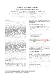
2. <strong>RECEIVER</strong> HARDWARE DESCRIPTION<br />
The core component of the receiver is the Zarlink’s<br />
GP2000 chipset (GP2015 and GP2021) [1]. The first<br />
one is an RF Front-end small format for Global<br />
Positioning System (<strong>GPS</strong>) receivers [2]. It is similar in<br />
capabilities to GP2010 but built in a TQFP package.<br />
The GP2021 [3] is a 12-channel C/A code baseband<br />
correlator for use in NAVSTAR <strong>GPS</strong> satellite<br />
navigation receivers. It is compatible with most 16-bit<br />
and 32-bit microprocessors, especially those by<br />
Motorola and Intel, with additional on-chip support for<br />
the ARM60 32-bit RISC processor [4]. The GP2021’s<br />
On-Chip Dual UART allows two serial communication<br />
ports to the receiver.<br />
Figure 1 - <strong>GPS</strong> receiver block diagram [5]
The microprocessor used in this receiver was an<br />
ARM60-B, also by Zarlink. It is a high performance 32<br />
bits RISC processor with a 32-bit data and address<br />
buses.<br />
Other important components are the <strong>GPS</strong> banddefinition<br />
SAW filter and a sub-miniature 10MHz<br />
Temperature Compensated Crystal Oscillator (TCXO).<br />
The general block diagram of the receiver is shown in<br />
Fig. 1. A photo of the receiver is shown in Fig. 2.<br />
Figure 2 - <strong>GPS</strong> receiver<br />
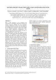
3. SOFTWARE DEVELOPMENT<br />
The development system used to design and test the<br />
<strong>GPS</strong> software was that of Mitel’s, <strong>GPS</strong> Architect.<br />
Zarlink was formerly Mitel Corporation.<br />
The full <strong>GPS</strong> Architect System contains:<br />
. A main board mounted in a plastic case;<br />
. An active antenna with magnetic mount and cable;<br />
. <strong>GPS</strong> software;<br />
. A software license agreement;<br />
. An ARM Toolkit;<br />
. An user guide documentation;<br />
. Power supply;<br />
. Two serial cables to connect the <strong>GPS</strong> Architect to a<br />
PC.<br />
The main board of the <strong>GPS</strong> Architect is built with the<br />
GP2000 chipset, the same of the receiver. This issue<br />
allows test and validates the software before it could be<br />
installed in the receiver.<br />
Figure 3 – The <strong>GPS</strong> Architect main board block<br />
diagram [6]<br />
The block diagram of the <strong>GPS</strong> Architect main board is<br />
shown in Fig. 03. Its photo is shown in Fig. 04.<br />
Figure 4 – The <strong>GPS</strong> Architect main board [6]<br />
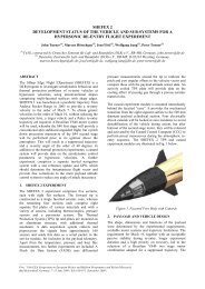
4. MISSION PROFILES<br />
The <strong>GPS</strong> receiver described in this paper was used in<br />
two campaigns, Angicos and Maracati II. The main goal<br />
of the Angicos Campaign, with a VS30 rocket flight<br />
launched from the CLBI, was to collect data from<br />
Argentina’s CONAE (National Commission for Space<br />
Activities) payload. In that payload there was another<br />
<strong>GPS</strong> receiver built by CONAE. Payload was, then,<br />
recovered from the sea.<br />
The VS30 rocket is a Brazilian sounding rocket by IAE<br />
(Space and Aeronautics Institute). The VS30 mission<br />
profile (Fig. 05) has a 121 km apogee with about 100<br />
sec of microgravity flight.<br />
Figure 5 - Angicos mission profile<br />
Maracati II was a campaign that allowed Brazilian<br />
academic experiments to access microgravity<br />
environment through a VSB30 rocket flight. It was<br />
launched from CLA, in Alcântara/Brazil, and reached<br />
the apogee at an altitude of 242 km, with 400 sec of<br />
microgravity. The payload was also recovered. The<br />
DLR (German Space Agency) participated with IAE in<br />
this campaign. Also, in a payload of VSB30, there was
another <strong>GPS</strong> receiver by DLR (German Aerospace<br />
Center).<br />
In both the CLBI and the CLA there are two tracking Cband<br />
radars and an S-band telemetry ground station.<br />
The data collected by the radar and by the telemetry<br />
were used in comparison with the positioning data<br />
provided by the <strong>GPS</strong> receiver. Since each payload had<br />
another <strong>GPS</strong> receiver, we expected to be able to<br />
compare the data provided by all these means with the<br />
data provided by the receiver under test.<br />
5. SOME PARTIAL RESULTS<br />
The positioning data provided by the <strong>GPS</strong> receiver were<br />
available at a 1Hz data rate. The NMEA sentences<br />
supplied by the receiver were GSV, GSA, GGA and<br />
RMC.<br />
5.1. RESULTS FROM THE ANGICOS<br />
CAMPAIGN<br />
On this flight the telemetry data collected cover the first<br />
72 seconds of flight. On the other side, this data covered<br />
all booster phase and the beginning of ballistic phase.<br />
During this entire time the <strong>GPS</strong> receiver was on a 3D<br />
fix status with at least 9 satellites being used for fix<br />
navigation data.<br />
5.1.1. COMPARISON TO THE SECOND <strong>GPS</strong><br />
<strong>RECEIVER</strong><br />
In Fig. 6 we can see the comparison between the<br />
parameter altitude (sentence GSA) provided by both<br />
receivers. At the end of the booster phase the Argentina<br />
<strong>GPS</strong> stopped sending data to the PCM telemetry<br />
encoder, so we could only compare the first 25 sec. of<br />
flight. As we can see, the curve provided by the data<br />
from Brazilian <strong>GPS</strong> was more stable and smooth.<br />
Figure 6 - ARG versus BRA altitude data<br />
5.1.2. COMPARISONS BETWEEN <strong>GPS</strong> AND<br />
RADAR TRAJECTORIES DATA<br />
Since the <strong>GPS</strong> data from the Argentina <strong>GPS</strong> receiver<br />
were not available after 25s of flight, we used the<br />
tracking position provided by the radar to verify the<br />
operation of the receiver under test.<br />
Because of this, all the geodetic data from the <strong>GPS</strong><br />
receiver had to be converted to ECEF coordinates just<br />
like the radar data. On the other side, this changing<br />
made it easier to calculate the differences (in meters)<br />
between the <strong>GPS</strong> and the radar data. It also made it<br />
simpler to calculate the rocket average speed and<br />
acceleration. As a sample, we can see in Fig. 7 both<br />
trajectories on a 3-axis chart.<br />
In the Fig. 8 we have a graphic with the differences<br />
between the <strong>GPS</strong> receiver and the radar positioning<br />
data. In fact, there are some small errors at the trajectory<br />
provided by the radar that will not be discussed in this<br />
article. Since the purpose of this first flight was only to<br />
validate the receiver in flight conditions, we can<br />
consider all ∆-values as the <strong>GPS</strong> error of positioning<br />
and the positioning points provided by the radar as our<br />
reference.<br />
Figure 7 - <strong>GPS</strong> and Radar data trajectories<br />
The points not recovered from the telemetry data are<br />
shown in a dashed line. The positioning data of these<br />
points were calculated by linear interpolation. In this<br />
graphic we see some oscillations at the end of the<br />
available data because of the data oscillations in the<br />
radar data. On the other side, even with these variations<br />
we can see that the average values of errors on each axis<br />
are less than 28m.<br />
Figure 8 - <strong>GPS</strong> positioning “errors"
If we consider all individual XYZ errors as a new vector<br />
we could call this an “error vector”. By calculating the<br />
mode of each vector, the value gives us a more<br />
representative number about our positioning error. As<br />
we can see in Fig. 9, maximum error occurs at the end<br />
of the booster phase (about 24 sec.) and decreases after<br />
that. Minimum value is at the beginning of flight (about<br />
1,2 m). The mean value is about 32 m.<br />
Figure 9 - Mode of error vectors (in meters)<br />
The rocket average velocity calculated by the <strong>GPS</strong><br />
receiver and the radar data is shown in Fig. 10. At the<br />
end of the booster phase the average speed was 1360<br />
m/s on the X axis.<br />
Figure 10 - Average speed on all axis (<strong>GPS</strong> x Radar)<br />
With respect to acceleration, the maximum value<br />
calculated was about 90 m/s 3 on the X axis at the end of<br />
the booster phase (Fig. 11).<br />
Figure 11 - Acceleration on X axis (<strong>GPS</strong> x Radar)<br />
Although the problem with the telemetry encoder that<br />
caused data loss after 72 seconds of flight, the receiver<br />
worked perfectly after the recovering of payload on the<br />
Angicos campaign. The same hardware was used in the<br />
Maracati II campaign.<br />
5.2. RESULTS FROM THE MARACATI II<br />
CAMPAIGN<br />
In Maracati II, the <strong>GPS</strong> receiver obtained navigation<br />
solutions for only one sample. This happened because<br />
of an operational power discontinuity, some minutes<br />
before launch. However, the receiver successfully got<br />
new satellite signals during the flight and allocated them<br />
into its correlator channels, as it is shown in Fig. 06.<br />
Even with the severe dynamics that VSB30 was<br />
subjected to, as it is shown in Fig. 12, the <strong>GPS</strong> receiver<br />
worked properly.<br />
12<br />
10<br />
8<br />
6<br />
4<br />
2<br />
0<br />
-2<br />
g<br />
15:32:33<br />
15:33:09<br />
15:33:45<br />
15:34:21<br />
Satélites usados Satélites rastreados<br />
15:34:57<br />
15:35:33<br />
15:36:09<br />
15:36:45<br />
15:37:21<br />
15:37:57<br />
15:38:33<br />
15:39:09<br />
15:39:45<br />
15:40:21<br />
15:40:57<br />
15:41:33<br />
15:42:09<br />
15:42:45<br />
15:43:21<br />
15:43:57<br />
15:44:33<br />
15:45:09<br />
15:45:45<br />
15:46:21<br />
Figure 12 Satellites tracked and used in the Maracati 2<br />
campaign<br />
12,0<br />
10,0<br />
8,0<br />
6,0<br />
4,0<br />
2,0<br />
0,0<br />
-2,0<br />
-4,0<br />
-6,0<br />
-8,0<br />
Aceleração<br />
-10,0<br />
15:35:00,05 15:35:26,85 15:35:53,65 15:36:20,45 15:36:47,25 15:37:14,05 15:37:40,85 15:38:07,65 15:38:34,45 15:39:01,25 15:39:28,05 15:39:54,85 15:40:21,65 15:40:48,45 15:41:15,25 15:41:42,05 15:42:08,85 15:42:35,65 15:43:02,45 15:43:29,25 15:43:56,05 15:44:22,85 15:44:49,65 15:45:16,45 15:45:43,25 15:46:10,05 15:46:36,85<br />
Figure 13- VSB30 acceleration profile on the Maracati 2<br />
campaign<br />
The VSB30’s altitude obtained by the Brazilian <strong>GPS</strong><br />
receiver is compared to the German data in Fig. 14. The<br />
spot shown occurred in sample 15:41:49,77 UTC.<br />
15:46:57
metros<br />
275000<br />
250000<br />
225000<br />
200000<br />
175000<br />
150000<br />
125000<br />
100000<br />
75000<br />
50000<br />
25000<br />
0<br />
15:35:00,40<br />
15:35:37,40<br />
15:36:14,40<br />
15:36:55,50<br />
15:37:33,80<br />
15:38:14,00<br />
15:38:50,20<br />
15:39:26,00<br />
15:40:01,80<br />
15:40:37,60<br />
15:41:13,60<br />
15:42:00,80<br />
15:42:39,40<br />
15:43:15,60<br />
15:43:52,20<br />
<strong>GPS</strong>-DLR<br />
<strong>GPS</strong>-AE<br />
Figure 14– Altitude: Brazilian x German <strong>GPS</strong> receivers (on<br />
the Maracati II campaign)<br />
6. CONCLUSIONS<br />
Although all results are partial, the receiver worked<br />
properly in high dynamic conditions. New tests will be<br />
provided to qualify the receiver. New modifications will<br />
be implemented to allow the receiver to be used in small<br />
satellites.<br />
7. REFERENCES<br />
1. Zarlink Semiconductor (1999). GP2000: <strong>GPS</strong><br />
Receiver Hardware Design. Online at<br />
http://www.zarlink.com/zarlink/an4855-appnote.p<br />
df (as of 04 April 2006).<br />
2. Zarlink Semiconductor (2007). <strong>GPS</strong> Receiver RF<br />
Front End. Online at http://www.zarlink.com/<br />
zarlink/gp2015-datasheet-sep2007.pdf (as of 05<br />
October 2007).<br />
3. Zarlink Semiconductor (2005). <strong>GPS</strong> 12-Channel<br />
Correlator. Online at http://www.zarlink.com/<br />
zarlink/gp2021-datasheet-aug2005.pdf (as of 04<br />
April 2006).<br />
4. Zarlink Semiconductor (2002). ARM60 Data Sheet.<br />
Online at http://www.zarlink.com/zarlink/<br />
p60armb-datasheet-jun2002.pdf (as of 04 April<br />
2006).<br />
5. Zarlink Semiconductor (2001). <strong>GPS</strong> Orion 12<br />
Channel Reference Design Online at<br />
http://www.zarlink.com/zarlink/an4088appnote.pdf<br />
(as of 04 April 2006).<br />
6. MITEL SEMICONDUCTORS. <strong>GPS</strong> Architect: 12<br />
channel <strong>GPS</strong> development system. 1997. Online at<br />
http://www.datasheetarchive.com/datasheets/<br />
Datasheet-021/DSA00371500.pdf. (as of 02 May<br />
2008).<br />
15:44:28,20<br />
15:45:08,00<br />
15:45:43,80<br />
15:46:19,60<br />
15:46:55,40